14. starptautiskÄ konference 2012 - Latvijas JÅ«ras akadÄmija
14. starptautiskÄ konference 2012 - Latvijas JÅ«ras akadÄmija
14. starptautiskÄ konference 2012 - Latvijas JÅ«ras akadÄmija
You also want an ePaper? Increase the reach of your titles
YUMPU automatically turns print PDFs into web optimized ePapers that Google loves.
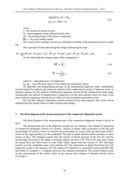
Proceedings of 14th International conference „Maritime Transport and Infrastructure - <strong>2012</strong>”J[ddtddt(t)] M M ( t) (t) 0,rR,(12)[4].Mwhere:J - the moment of inertia of rotor;M - electromagnetic torque influencing the rotor;M R – the rotating torque of the electro compressor,( t ) - the rotor rotation speed.The values of the windings currents are calculated according to the expressions given in paperThe expression for the electromagnetic torque influencing the rotor:p {[Ψ (t) Ψ(t))] i(t) [Ψ (t) Ψ(t)] i(t) [Ψ (t) Ψ(t)] i(t)}(13)3CBAOn the other hand the rotating torque of the compressor is:ACBABCNM ;(14)NN i,(15) kmwhere N i – indicating power of compressor, k , m – is an efficiency factor of the compressor and electric motor.An algorithm and programming package of the mathematical approach under considerationwas developed for analysis and numerical solution of the mathematical model of induction motor indynamic regimes. For the solution of differential equations systems for the mathematical model underconsideration the method of Runge-Kutta is supposed to be the most optimal where the range of thestep is defined complying with the pre-set values of local and global quantisation errors.The full flux linkage of the phases and the position of the main magnetic flux vector can beobtained from the instant values of stator currents and voltages.3. The block diagram of the measurement part of the compressor diagnostic systemThe block diagram of the measurement part of the compressor diagnostic system is given infig.4.The measurement part of the diagnostic system has two channels. The channel of measuringof compressor parameters consists of 5 sensors - sensors of instant value of pressures of the first andsecond stages (Р 1 and Р 2 ), sensor of vibration of accelerometer Q, sensor of the top dead centre (TDC),sensor of the angle position φ of the crankshaft. The data in square brackets define positions of thesesensors in fig.1. The analogue signals from the sensors of instant pressure of the first (Р 1 ) and thesecond stage (Р 2 ) come to the inputs of analogue-digital converter CAP. This is the same place wherethe signals from the vibro-sensor Q come. Pulse (digit) signals from the sensors of TDC and angleposition φ of the crankshaft come to the interface I/O. The information in digital form from the CAPoutput also comes to the interface I/O. The output if I/O interface is connected to microcontroller MKand further to computer C. Computer processes the obtained information. The second channel existsfor the measurement of the instant values of the currents and voltages of induction electric motor(21 in fig.1).30


