nivocap c-200/300 - Nivelco Process Control Co., Inc.
nivocap c-200/300 - Nivelco Process Control Co., Inc.
nivocap c-200/300 - Nivelco Process Control Co., Inc.

You also want an ePaper? Increase the reach of your titles
YUMPU automatically turns print PDFs into web optimized ePapers that Google loves.
NIVOCAPC-<strong>200</strong>, C-<strong>200</strong> Ex, C-<strong>300</strong>Two-wire compact capacitancelevel transmitterManufacturer:NIVELCO <strong>Process</strong> <strong><strong>Co</strong>ntrol</strong> <strong>Co</strong>.H-1043 Budapest, Dugonics u. 11.Phone: (36-1) 889-0100 Fax: (36-1) 889-0<strong>200</strong>E-mail: sales@nivelco.com www.nivelco.comBKI 03 ATEX 043X ♦ cbr2052a0600p_01 ♦ 36/1
2/36 ♦ BKI 03 ATEX 043X ♦ cbr2052a0600p_01
CONTENTS1.INTRODUCTION ........................................................................... 52.ORDER CODE .............................................................................. 63.TECHNICAL DATA ....................................................................... 73.1. ADDITIONAL DATA FOR EX MODELS .......................................... 83.2. CONDITIONS OF EX APPLICATION ............................................. 83.3. SAP-202 DISPLAY MODULE .................................................... 83.4. DIMENSIONS........................................................................... 93.5. ACCESSORIES ...................................................................... 103.6. MAINTENANCE AND REPAIR ................................................... 104.INSTALLATION .......................................................................... 114.1. MOUNTING AND WIRING......................................................... 114.2. CHECKING OF THE LOOP CURRENT......................................... 125.PROGRAMMING......................................................................... 135.1. PROGRAMMING WITHOUT DISPLAY MODULE ............................ 145.2. PROGRAMMING WITH THE SAP-202 DISPLAY MODULE............. 175.2.1 Volume programming5.2.2 SAP-202 display module.............................................. 175.2.3 Steps of the programming............................................ 185.2.4 Indications of the SAP-202 Programming Module andthe LEDs ...................................................................... 195.2.5 QUICKSET................................................................... 215.2.6 Full parameter programming........................................ 236.PARAMETERS – DEFINITIONS AND PROGRAMMING ...........246.1. MEASUREMENT CONFIGURATION............................................246.2. CURRENT OUTPUT.................................................................276.3. MEASUREMENT OPTIMALISATION............................................286.4. VOLUME MEASUREMENT........................................................286.5. 32-POINT LINEARISATION.......................................................296.6. SERVICE PARAMETERS (READ ONLY) ......................................316.7. TEST PARAMETERS ...............................................................316.8. SIMULATION..........................................................................326.9. ACCESS LOCK.......................................................................327.ERROR CODES ..........................................................................338.SUMMARY OF THE PARAMETERS ..........................................35BKI 03 ATEX 043X ♦ cbr2052a0600p_01 ♦ 36/3
CAPACITANCE LEVEL MEASUREMENThigh level (max)Transmitter range inLEV and VOL modeP11P10LEVELLast element of the linearisation table(% LEV and VOL)LEV = levelVOL = volumeFirst element of the linearisation table(%, LEV and VOL)4/36 ♦ BKI 03 ATEX 043X ♦ cbr2052a0600p_01
Thank you for choosing a NIVELCO instrumentWe are sure that you will be satisfied throughout its use1. INTRODUCTIONNIVOCAP CT-<strong>200</strong> is a two-wire capacitance level transmitter for measuring level and volume (weight) of conductive or not-conductive liquids or free flowingsolids.APPLICATIONThe active probe of the unit and the conductive wall of the vessel (or a grounded reference probe if the wall is not conductive) make up the plates of a capacitor.Insulator of the probe, surrounding air or the material in the tank provide dielectric material.If the tank is empty the basic capacitance is C0 while the dielectric coefficient “εr” of the air is 1. If the air will be replaced by material with higher dielectricconstant than that of the air, the capacitance will be changed, i.e. capacitance will increase with rising material. This change of the sensed capacitanceconverted to output signal will be proportional to the level change. The same time the condition of level gauging is direct proportionality between the levelchange and the change of the capacitance.The value of capacitance also depends on the distance between the plates, the condition above will be met if the active probe is parallel to he tank wall or withthe reference probe. Thus reference probe should be used in a tank with unusual shape or cylindric tank in a horizontal position even if the wall is conductive,provided the medium is not conductive.Due to the level measurement on the capacitance principle it is essential to measure and store capacitance at two different levels in the tank (teaching), whenthe unit is “learning “ surrounding conditions of the actual application (e.g. C0 is different on the workshop bench and on site in the tank etc.).Improper selection of the probe and very low dielectric constant may prevent the measurement.For conductive materials (e.g.. water, acid,, bases, solutions with water, etc.) insulated active probes should be used., while value of the dielectric constant isindifferent. Both insulated and uninsulated probes can be used for non conductive materials but dielectric constant must be over 1.5 (εr > 1.5).VOLUME AND WEIGHT MEASUREMENTThis measurement is supported by the volumetric calculation feature and arithmetical formula for the most commonly used tank shapes in the software.Thus measuring level, volume or weight of the medium in the tank can be transmitted and displayed.LINEARISATIONIf there is no direct proportionality between the change of capacitance and change of level the 32-point linearisation feature should be applied. Linearisation isthe method of assigning calibrated volume values to level values measured by the unit.BKI 03 ATEX 043X ♦ cbr2052a0600p_01 ♦ 36/5
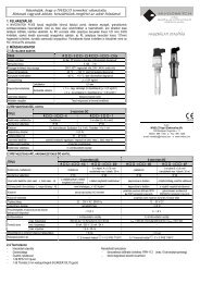
2. ORDER CODENIVOCAP C - - * Not all combinations possible!FUNCTION CODE PROBE CODEENCLOSUREINTRUSION LENGTHCODEMATERIALCODE ROD CODEOUTPUT / EXCODETransmitter T Rod / insulated 1” BSP R Aluminium 2 0 0 m 0 m 0 4 ... 20 mA / standard 2Transmitter + display B Rod / uninsulated 1” BSP P Plastic 3 1 1 m 0,1m 1 4 ... 20 mA HART/st. 4Transmitter, high temp H Cable / insulated 1” BSP K 2 2 m : : 4 ... 20 mA / Ex 6Tx, high temp + display P Cable / uninsulated 1” BSP L 3 3 m 0,9m 9 4 … 20 mA HART / Ex 8Rod / insulated 1” NPTARod / uninsulated 1” NPT C CABLECable / insulated 1” NPT E 0 0 m 0 m 0Cable / uninsulated 1” NPT G 1 10 m 1 m 12 20 m : :9 m 9*The order code of an Exversion should end in ‘Ex’.Ex models are only available forthe standard temperatureversions.ACCESSORIES:HART MODEMDISPLAY MODULEWEIGHT for cable probeSAT-304SAP-202CTK-103-0M-40001REFERENCE (TUBE) PROBE NIVOCAP C – 1 – 0VERSION / THREAD CODE REF. PROBE CODE INSERTION LENGTH<strong>Co</strong>axial tube BSP A Tube 1½” F CODE ROD / TUBE CODE<strong>Co</strong>axial tube NPT D Rod 1” P 0 0 m 0 m 0Reference rod BSP F 1 1 m 0.1 m 1Reference rod NPT E 2 2 m : :3 3 m : :0.9 m 96/36 ♦ BKI 03 ATEX 043X ♦ cbr2052a0600p_01
3. TECHNICAL DATARod probeCable probeRange 0.2 ... 3 m 1 ... 20 m<strong>Process</strong> connection St.St. DIN 1.4571Material of wettedpartsFully or partially PFA coated St. St.ProbeFully or partially FEP coated St. St. cable(DIN 1.4301)Enclosure materialAluminium casting, Plastic (PBT), glass fibre reinforced (PBT)Medium temperature (See: temp. diagram) standard: -30 °C ... +130 °C, high temperature: – 30 °C ... +<strong>200</strong> °CPressure (See pressure diagram) maximum 4 MPa (40 bar) +20 °C maximum 1.6 MPa (16 bar)Ambient temperature (See temp. diagram -25 °C ... + 70 °CMaximum tensile load – 7.7 kNSaturation capacitance of the probe ~600 pF/m ~<strong>200</strong> pF/mAnalogue: 4 ... 20 mA. 2-wire (3.9 … 20.5 mA),OutputRmax = Ut – 11.4 V / 0.02 A isolated, protection against power supply transientSAP-202 display module: 6-digit LCD, engineering units and bargraphHART feature, load resistance ≥ 250 ohmVoltage output for current testVoltage measurement on serial resistance: 10 mV / 1 mACapacitance range0 pF ... 5 nFRange of transmitted capacitance10 pF, or 10% (min. SPAN)Damping0, 3, 6, 10, 30, 60, 100, <strong>300</strong> sFault indicationBlinking of COM and VALID LED andtransmitting 3.8 or 22 mA fault indication current selected by programmingPower supply / current consumption12 ... 36 V DC, maximum 22 mA / 48 … 800 mWAccuracy± 0.3 % (related to the length of the probe)Temperature coefficient ± 0.02% / °CElectric connectionM20x1.5 metal or plastic cable gland, M20x1.5 or 2 x ½” NPT thread for cable protection tube.<strong>Process</strong> connection1" NPT or BSPIngress protection Probe: IP 68, Enclosure: IP 67Electric protectionProtection Class IIIMass 2.3 kg with 0.5 m probe 1.9 kg with 3 m probeBKI 03 ATEX 043X ♦ cbr2052a0600p_01 ♦ 36/7
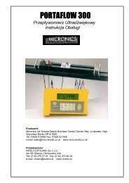
TEMPERATURE DIAGRAMPRESSURE DIAGRAM+70 Tambient [[80+45+4560-30-250T [+70 +130-30+70 Tambient T [-250 +70 +<strong>200</strong>402016STANDARD PROBEHIGH TEMPERATURE PROBE-20-20P medium ( bar )80 120 160 18020 4060<strong>200</strong>Tmedium( °C )3.1. ADDITIONAL DATA FOR EX MODELSEx markingII 1G EEx ia IIB T6Intrinsical safe dataCi ≤ 15 nF, Li ≤ <strong>200</strong> µH, Ui ≤ 30 V, Ii ≤ 140 mA, Pi ≤ 1 WPower supply Uo < 30 V, Io < 140 mA, Po < 1 W.3.2. CONDITIONS OF EX APPLICATIONTemperature table1. The unit should be powered by an intrinsically safe signal processor with [EEx ia IIB] or [EEx ia IIC] certification. Temperature class T62. The tank and the level measuring instrument shall be connected to an EP network with copper wiring q ≥ 4 mm 2. . Tambient 70 °C3. The Teflon coating of the rod and cable probes may be charged electrostatically, therefore: Tmedium 80 °C• the unit should only be used for level measurement of conductive medium and its specific resistance must not exceed 10 4 Ωm, even under the most unfavourableconditions and at the most unfavourable place.• method and the speed of filling or emptying of the tank should be selected in accordance with the medium properties.• the electronic circuitry of the probe is grounded. An equipotential network should be formed along the intrinsically safe circuit. Distance between the transmitter and theintrinsically safe power supply (accommodated in the non -hazardous area) must not exceed 100 m.3.3. SAP-202 DISPLAY MODULEDisplay6 digit LCD, engineering units and bargraphAmbient temperature -25 °C … +70 °CEnclosure PBT glass fibre reinforced plastic (DuPont ® )8/36 ♦ BKI 03 ATEX 043X ♦ cbr2052a0600p_01
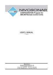
3.4. DIMENSIONSROD PROBECT-2, 3-CB-2, 3-89CABLE PROBECT-2, 3-CB-2, 3-89HIGH TEMPERATUREROD PROBECH-2-CP-2-89<strong>Co</strong>verDisplay unitElectronicsØ 14Ø 12)136L N136Ø 5Ø 2,5)L NØ 14Ø 12)191L NHousingTransducerBKI 03 ATEX 043X ♦ cbr2052a0600p_01 ♦ 36/9
DISPLAY MODULE HART MODEM REFERENCE (TUBE) PROBESAP-202 SAT-304 CF-1-0563946LEV VOL % mAPROGFAILt °F sec min hour day9,540 21COMVALID793.5. ACCESSORIES• Certificate of Warranty• Installation and Programming Manual• Declaration of conformity• 2 pcs M20x1.5 cable gland3.6. MAINTENANCE AND REPAIRThe unit do not require regular maintenance.Repairs during or after the warranty period are effected at the Manufacturers. The equipment sent back for repairs should be cleaned or neutralised (disinfected)by the User.10/36 ♦ BKI 03 ATEX 043X ♦ cbr2052a0600p_01
4. INSTALLATION4.1. MOUNTING AND WIRINGThe probe has to be installed vertically and for non-conductive materials reference probe should be used.The NIVOCAP probes are mounted by 1" or 1½" process connections using S = 41 or S = 55 open end wrench, respectively.It is recommended to fix the bottom end of the cable probes. This can be accomplished by fixing the cable loop or bore hole to the tank bottom or by the use ofweight.The active probe and the reference probe should be installed parallel and next to each other.ACTIVE PROBE AND CONDUCTIVE TANK WALL ASREFERENCE PROBEACTIVE PROBE AND REFERENCE (TUBE) PROBEACTIVE PROBE AND REFERENCE (ROD) PROBETank Tank TankBKI 03 ATEX 043X ♦ cbr2052a0600p_01 ♦ 36/11
TEMPERATUREElectronics of the unit should be protected with shelter against development oftoo high temperature by direct sunshine.SunshadeDisplay unitconnec torWIRING• Power must be switched off before wiring the unit.• This instrument use electronic components that may be damaged by staticelectricity thus apply precautions commonly used e.g. touching a properlygrounded point before removing cover of the enclosure• After removal of the cover of the housing and taking out the display module(if any), the screw terminals can be accessed. Suggested cable core crosssection 0.5 ... 1.5 mm 2 . The unit has first to be grounded by the inner orouter grounding screw.• After connecting the cable and unit programmed proper sealing and closingshould be ensured.<strong>Co</strong>nnector formeas. of loop current1 2U- U+1/2” NPTM20x1,51 2 3 4 5 6GND4...20 mA loop currentand supply voltage (HART)2 3I-I+1/2” NPTM20x1,54.2. CHECKING OF THE LOOP CURRENTAfter removal of the cover of the housing and taking out the display module (if any), voltage measuring instrument should be connected to the test connector.Setting range to <strong>200</strong> mV the loop current can be measured with an accuracy of ~ 0.5%.12/36 ♦ BKI 03 ATEX 043X ♦ cbr2052a0600p_01
5. PROGRAMMINGSince NIVOCAP is not measuring level directly, the basic element of the programming is measurement (learning) at two different levels during which theinstrument is learning conditions of the actual application (shape of the tank, medium to be measured, etc.). To reach accuracy given in the table of theTechnical Data these two levels should be possibly near to both end of the (rod or cable) probes (See Operation and Programming of NIVOCAP on page 4)Learning will be represented (with Programming Without Display Module 5.1 and with QUICKSET) by the adjustment of 4 and 20 mA better to say assignment of0% and 100% to these two output values respectively. In units without display module level will be proportional to the output current while QUICKSETprogramming will make possible display in % only.If level, level in percentage, volume or volume percentage should be measured (a≠0 in P01) and measured values should be displayed in engineering units ofthe length [e.g.. m] and volume [e.g. m3] two data pair of the linearisation table (0% and relevant minimum level in e.g. in m as well as 100% and the relevantmaximum level should be entered. Linearisation should be disabled. (See P47 and P48 on page 30).Not only the minimum (0%) and maximum (100%) level of the actual application can be assigned (directly) to the 4 and 20 mA output.If for some reasons of the technology the tank can not be filled to the maximum or emptied to the minimum level the 4 and the 20 mA can indirectly also beassigned to the minimum (0 %) and maximum (100 %) with the help of two intermediate levels (say to 15% and to 80%).Obviously - for the sake of accuracy – it is advised to fill/empty the tank to the maximum/minimum level and perform “direct” assignment as soon as possible.The unit can also be programmed for inverse operation (4 mA = full and 20 mA = empty).• Programming without display module (See 5.1)The transmitter is fully operable without display module. Basic parameters such as assignment of 4 and 20 mA to the minimum and maximum level, faultindication by the output current and damping can be programmed• Programming with SAP-202 display module (See 5.2)− QUICKSET – 4 parameters can be programmed (See 5.2.4). Programming of the basic parameters will be aided by images on the display. Measuredvalues can only be displayed in percentage.− Full parameter programming (See 5.2.5.). All parameters and programming features of the unit can be accessed such as (measurement configuration,outputs, measurement optimalisation, 11 pre-programmed tank shapes for volume calculation, 32 point linearisation.− Measured values can be displayed in engineering unitsThe unit will measure during programming in accordance with the previous parameters. The new, modified parameters will only be effective after returning to theMeasurement ModeIf the transmitter is left in Programming Mode by mistake, it will automatically return to Measurement Mode after 30 minutes and will operate with the parametersentered during the last programming completed.FACTORY DEFAULTCurrent output and bargraph is proportional to the (capacitance) level percentage. 4 mA and 0% is assigned to the 0 capacitance percentage (low level). 20 mAand 100% is assigned to 100% capacitance (high level). Current output of the fault indication is 22 mA. Damping: 10 sec.Note: the 4 and 20 mA assignment is an absolute necessity of the programming.BKI 03 ATEX 043X ♦ cbr2052a0600p_01 ♦ 36/13
5.1. PROGRAMMING WITHOUT DISPLAY MODULEPROGRAMMING FEATURES• 4 mA output current (direct) assignment to the minimum (0%) level• 20 mA output current (direct) assignment to the maximum (100%) level• 4 mA output current (indirect) assignment to the minimum (0%) level by means of anintermediate level• 20 mA output current (indirect) assignment to the maximum (100%) level by means of anintermediate level• Fault indication by the current output: 3.8 mA; or 22 mA• Damping (3 sec, 10 sec, 60 sec)• Reset to the Factory DefaultRemark: current output can be programmed for inverse operation: 4 mA = 100%(full), 20 mA = 0% (empty)Procedure of programming: press programming keys in the proper sequence and watch state of the LEDs. See interpretation of the LEDs below= LED “Off”, = LED Blinking, = LED “On” lit, = LED-s blinking alternatively = Do not care“Direct” assignment of 4 mA to the minimum level, 0% (or maximum level for inverse operation)Fill the tank to the minimum (maximum) levelPROGRAMMING STEPSLED STATE AFTER PROGRAMMING STEP1) Press key and keep it pressed = NIVOCAP in programming mode2) Press additionally key and keep it pressed = Assignment of 4 mA to the level in the tank3) Release both keys = Programming completed“Direct” assignment of 20 mA to the maximum level, 100%, (or minimum level for inverse operation)Fill the tank to the maximum (minimum) levelPROGRAMMING STEPSLED STATE AFTER PROGRAMMING STEP1) Press key and keep it pressed = NIVOCAP in programming mode2) Press additionally key and keep it pressed = Assignment of 20 mA-to the level in the tank3) Release both keys = Programming completed14/36 ♦ BKI 03 ATEX 043X ♦ cbr2052a0600p_01
Indirect assignment of the minimum and maximum level to the output current with partially filled tankFor this programming the output current is to be measured on the test points as described in 4.2. Should higher accuracy be needed the current meter should beinserted in the 4 … 20 mA loop.Assuming a tank filled up to 15% approximately and the task is to accomplish “indirect” assignment of low level to 4 mA the procedure is the following. Since thecurrent output at the level of 15% is Iout= (16 mA x 0.15) +4 mA = 6.4 mA the current output should be changed with the keys , , until the value of 6.4appears on the current meter.This procedure should be repeated with another, higher level for indirect assignment of 20 mA to the maximum level.Obviously – for the sake of greater accuracy (it is not even sure whether the assumption of 15% is correct) –the “direct” assignment should be accomplished assoon as it is possible“Indirect” assignment of 4 mA to the minimum level with partially filled tankPROGRAMMING STEPSLED STATE AFTER PROGRAMMING STEPS1) Press key and keep it pressed = NIVOCAP in programming mode2) Press additionally key E and keep it pressed, then release keys = 4 mA in programming mode3) Set output current with keys , to the required valueSave adjustment with key E or with key you can return to the value of 4 mA= 4 mA in programming mode4) Release the key = Programming completed“Indirect” assignment of 20 mA to the maximum level with partially filled tankPROGRAMMING STEPSLED STATE AFTER PROGRAMMING STEPS1) Press key and keep it pressed = NIVOCAP in programming mode2) Press key and keep it pressed, then release keys = 20 mA in programming mode3)Set output current with keys , to the required value = 20 mA in programming mode4) Save adjustment with key E or with key you can return to the value of 20 mA = 20 mA in programming mode5) Release the key = Programming completedBKI 03 ATEX 043X ♦ cbr2052a0600p_01 ♦ 36/15
Selecting “Fault indication” by the current outputAs a result of the programming current output will be 3,8 mA; 22 mA.PROGRAMMING STEPSLED STATE AFTER PROGRAMMING STEPS1) Press key and keep it pressed = NIVOCAP in programming mode2) Press additionally key E , orand keep it pressed= - 3.8 mA- 22 mA3) Release both keys = Programming completedAdjustment of DAMPINGPROGRAMMING STEPSLED STATE AFTER PROGRAMMING STEPS1) Press key E and keep it pressed = NIVOCAP in programming mode2) Press additionally key , or– 3 sec,or= – 10 secand keep it pressed– 60 sec3) Release both keys = Programming completedReturn to DEFAULTPROGRAMMING STEPSLED STATE AFTER PROGRAMMING STEPS1) Press key and keep it pressed = NIVOCAP in programming mode2) Press key E and keep it pressed = loading DEFAULTIndication of programming error with the LEDPROGRAMMING STEPS LED STATE AFTER PROGRAMMING STEPS = FAULT INDICATED CORRECTIONAny programming attempt = blinking twice = no stable surface Wait for stable surfaceAny programming attempt = blinking three times = no access possible With SAP-202-only see 5.2 (P99)Any programming attempt = blinking four times = NIVOCAP not in default With SAP-202-only see 5.2 (P01)16/36 ♦ BKI 03 ATEX 043X ♦ cbr2052a0600p_01
5.2. PROGRAMMING WITH THE SAP-202 DISPLAY MODULEThe NIVOCAP should be adjusted to the process by programming the parameters. The SAP-<strong>200</strong> Display Module can be used to display the parameters whileprogramming and measurement values during measurement.The SAP-<strong>200</strong> supports two separately accessible programming modes as below.QUICKSET (See 5.2.5)This feature is for quick programming of the 4 basic parameters like with programming without display module but aided by images on the display.Measured values can only be displayed in percentage.• Assignment of min level to 4 mA• Assignment of max level to 20 mA• Damping• Fault indication by the current outputFull parameter programming (See 5.2.6)Highest level programming with availability of all parameters and features such as:• Measurement configuration• Adjustment of outputs• Measurement optimalisation• 11 pre-programmed tank shapes for volume calculation• 21 pre-programmed formula for flow metering5.2.1 VOLUME PROGRAMMINGProcedure 1: when the level and the tank dimensions are known.Linearisation table is disabled (P47=0) but the first two datapairs have to be entered in the linearization table (P48)1 st datapair: for 0% the minimum level value (in measurement units)2 nd datapair: for 100% the maximum level value (in measurement units)As in this case the transmitter calculates the volume based on a volume formula the tank parameters have to be set in parameters P40-P45.Procedure 2: when the level – volume relationship is known.Linearisation table is enabled (P=47=1) and linearization table (P48) has to be filled in with known volume values belonging to different levels. The table mustcontain the values for 0% and 100% level in every case.BKI 03 ATEX 043X ♦ cbr2052a0600p_01 ♦ 36/17
5.2.2 SAP-202 DISPLAY MODULESymbols used on the LCD:• LEV – Level measurement mode• VOL – Volume measurement mode• PROG - Programming mode• FAIL - Measurement / device error• - Level changing direction• Bargraph assigned to the level or volumet °F sec min hour daySymbols used on the frame:• M – Metric (European) system• US – US (Anglo-Saxon) systemLED is lit• COM – digital (HART) communicationVALID – value within the valid range5.2.3 STEPS OF THE PROGRAMMINGProgramming will be performed by pressing and releasing the relevant one or two keys (simultaneously). Find a short overview of the programming whiledetailed descriptions are under 5.2.5 and 5.2.6.Single key pressingE : Selection of address and step to the value of the parameterSelection of the parameter value and step back to the address: To move the blinking of the digit to the left: <strong>Inc</strong>reasing value of the blinking digit: Decreasing value of the blinking digityy:xxxxyy Parameter address(P01, P02…P99)xxxx Parameter value (dcba)bargraph18/36 ♦ BKI 03 ATEX 043X ♦ cbr2052a0600p_01
Double key pressingPress the two keys simultaneously for desired programming stepEntering/quitting programming mode Basic steps while parameter address is blinking Basic steps while parameter value is blinkingReturn to DEFAULTFull parameterAccessQuicksetCancel all modifications **Return to DEFAULT *Cancel modifications ofparameter value *Return to DEFAULTLearning* LOAD readout ** CANCEL readout* cancellation immediatelly activeNotes:If the parameter value is not accessible i.e. the parameter address keeps blinking after pressing ENTER E ,• the parameter is either a read-out type, or• the secret code prevents the modification (see P99).If the modification of the parameter value is not accepted i.e. the parameter value keeps blinking after pressing ENTER E ,• the modified value is either out of the range, or• the code entered is not valid for this parameter5.2.4 INDICATIONS OF THE SAP-202 PROGRAMMING MODULE AND THE LEDSt °F sec min hour dayLED indication• VALID-LEDlit in case of stabilised levelblinking if level changes• COM-LEDsee description of HARTBKI 03 ATEX 043X ♦ cbr2052a0600p_01 ♦ 36/19
SAP-202 indicationsDepending on the measurement one of thebelow symbols will lit and the processvalue displayed (see P01 chapter 6.1).Engineering units will be indicated directlyor by the lit arrow showing towards themon the frame• % percentage• LEV level• VOL volume• FAIL (blinking) Error code displayedThe following process values can be displayed• Volume– if programmed so• Level – if programmed so• Warning indications – FAIL blinkingIf the FAIL LED is ON the code of the error can be displayedand the output current will be in accordance with the FaultindicationIf the FAIL LED is blinking the code of the error can bedisplayed and the output current will be in accordance withthe measured value.(mA)Actual current output value can be displayedby pressing DOWN .(Vol / Flow)See P01for possible readouts(Distance)(Error)20/36 ♦ BKI 03 ATEX 043X ♦ cbr2052a0600p_01
5.2.5 QUICKSETSuggested for simple applicationsQuick programming of the 4 basic parameters (like with programming without display module but) aided by images on the display. Measured values can onlybe displayed in percentage.QUICKSET can only be used in (%)(DEFAULT) mode (See P01 in Full Parameter Programming 5.2.6).KeysFunctionE + (min. 3 s) Enter/Quit QUICKSET programming mode+ LEARNING function, , Adjustment of digit value (increase, decrease) moving blinkingESaving displayed value and step to the next screen+ Reload value before modification (CANCEL)E + (min 3 s) Return to DEFAULT+ Display DEFAULTScreensL:xxxxActionsAssignment of 4 mA to the minimum level , %Fill the tank to the level required. After entering the Quickset programming mode the learning function can be startedwith the double key pressing + . During learning the image „Store” is displayed.The parameter value represents filling in %.“Indirect” assigment of 4 mA to the minimum level with partially filled tank:Following learning enter the momentary % value of level with the buttons.The output current will be set in accordance % value.BKI 03 ATEX 043X ♦ cbr2052a0600p_01 ♦ 36/21
ScreenU:xxxxEr:xxxxdt:xxxxActionsAssignment of 20 mA to the maximum level , %Fill the tank to the level required. After entering the Quickset programming mode the learning function can be startedwith the double key pressing + . During learning the image „Store” is displayed.The parameter value represents degree in %. “Indirect” assigment of 20 mA to the maximum level with partially filledtank: Following learning enter the momentary % value of level with the buttons. The output current will be set inaccordance % value.“Error indication” by the output currentPressing or either of two outputs can be selected: Indication of “3,8” or “22” should apply for 3,8 or 22 mA currentoutputDEFAULT 22 mADamping – To select damping keys / should be usedDEFAULT 10 secNote:– Current output can also be programmed for inverted operation: 4 mA = 100% (Full), 20 mA = 0% (Empty)– Description of failures can be found under 7 Error <strong>Co</strong>des.22/36 ♦ BKI 03 ATEX 043X ♦ cbr2052a0600p_01
5.2.6 FULL PARAMETER PROGRAMMINGFull Parameter Access is the highest programming level to access all features provided by the NIVOCAP, level, volume and weight can also bedisplayed in engineering units.Description of the parameters can be found under 6. paragraph.KeysFunctionE + (at least for 3 sec) Enter/quit Full Parameter Programming mode. Entering programming mode parameter modified last time is blinking.During programming „PROG” is lit while the screen is as below:yy:xxxxyy Parameter address (P01, P02 … P99)xxxx Parameter value (dcba)BargraphMeasuring is going on during programming in accordance with the old parameter set. New parameter set will be valid after returning to theMeasurement Mode.Steps and indications of the Full Parameter Access programming modePressing Keys While Parameter address is blinking While Parameter value is blinkingE++Selecting parameter address and step to the parameter valueCancel all modifications of the actual programming phase.Pressing for 3 sec is required while CANCEL will be displayed forwarningDevice will be returned to Factory Default.Since all parameters will be overwritten “LOAD” will appear on thedisplay first:– to confirm, press E– to escape, press any other keyModification of the parameter values will be saved.Return to the parameter address.Modification of the parameter value will be neglectedReturn to the parameter address without saving themodifications.Default parameter will be loaded(and saved by pressing ENTER E ).Move blinking (changeability) of the digit to the left/ Modify the blinking digit (increase, decrease) or scroll up/downBKI 03 ATEX 043X ♦ cbr2052a0600p_01 ♦ 36/23
6. PARAMETERS – DEFINITIONS AND PROGRAMMING6.1. MEASUREMENT CONFIGURATIONP00: - c b a Engineering Unit SystemFactory default will be reloaded in the corresponding engineering units by programming this parameter. Therefore all parameters have to be set again.aOperating mode0 Always 0Engineering unitsb(according to „c”)MetricUS0 m ft1 cm <strong>Inc</strong>hAttention: mind the sequence!When programming this parameter theright side value “a” will be blinking first.cCalculation system0 metric1 USDEFAULT: 00024/36 ♦ BKI 03 ATEX 043X ♦ cbr2052a0600p_01
P01: - - - a Measurement modeParameter value „a” will determine the basic measurement value that will be displayed and proportional with the current output. Depending on thevalue of “a” process values as listed in the 3 nd column can also be displayed by pressing NEXT . For return to the display of the basic value theENTER E key should be pressed.Measurement mode DisplayaDisplayed valuesTransmitted value symbol0 Capacitance % % PercentageAttention: mind the sequence!When programming this1 Level LEV Levelparameter the right value “a” will2 Level percentage LEV% Level percentage, Levelbe blinking first.3 Volume VOL Volume, Level4 Volume percentage VOL% Volume percentage, Volume, LevelNote:If the change of the level is proportional with the change of the capacitance there will be no difference between relative % (a = 0) and level % (a = 2).P02: - - b a Engineering unitsa0 Always 0Attention: mind the sequence!When programming thisparameter the right value “a” willbe blinking first.This table is to be understood according to P00(c), P01(a) and P02(c) and irrelevant with measuring percentage ( P01(a)= 2 or 4 )bVolume Weight (See also P32)Metric US Metric US0 m 3 ft 3 tonne lb (pound)1 litre gallon tonne tonneBKI 03 ATEX 043X ♦ cbr2052a0600p_01 ♦ 36/25
P03: - - - a Displayed values – RoundingVolume (VOL) displayValue displayed Display arrangement0,000 – 9,999 x,xxx10,000 – 99,999 xx,xx100,000 – 999,999 xxx,x1000,000 – 9999,999 xxxx,x10000,000 – 99999,999 xxxxx,x100000,000 – 999999,999 xxxxxx,x1 million – 9,99999*10 9x,xxxx : e(exponential form)over 1 x 10 10(overflow) Err4Decimal position will be shifted with increasing value displayed.(See table at the left).Values over one million will be displayed in exponential format whereas thevalue (e) represents the exponent. Over the value of 1x10 10 Err4 (overflow) willbe displayed.RoundingSteps in the displayedParameter value “a”values0 1 (no rounding)1 22 53 104 205 5026/36 ♦ BKI 03 ATEX 043X ♦ cbr2052a0600p_01A couple of millimetres of fluctuation of the basic DIST value (e.g. due towaves) will be enlarged by the mathematical operations. This enlargedfluctuation in displaying VOL or FLOW can (if disturbing) be avoided byrounding to be set in P03. Rounding value 2, 5, 10 etc represents the steps bywhich the calculated value will be changed in its (one or two) last digit(s).Examples:P03 = 1 steps by 2: 1,000; 1,002; 1,004P03 = 5 steps by 50: 1.000; 1.050; 1,100 or 10.00; 10.05(0); 10.10(0);10,15(0)(the 0 from the steps 50, 100, 150 etc will not be displayed)DEFAULT: 0P05: Lower (learning) level of the operating rangeProgramming this parameter 0% of level will be assigned to the capacitance measured in the actual application i.e. the unit will “learn” conditionsof the applicationProgramming can be started by double key pressing of + . While learning „Store” will be displayed.P06: Upper (learning) level of the operating rangeProgramming this parameter 100% of level will be assigned to the capacitance measured in the actual application i.e. the unit will “learn”conditions of the applicationProgramming can be started by double key pressing of + . While learning „Store” will be displayed.
If level, level percentage, volume or volume percentage should be measured (a ≠0 in P01) as well as level and volume should be read with relevantengineering units, then first data pair (e.g. 0% and corresponding minimum level in [m]and last two data pair (e.g. 100% and corresponding maximumlevel in [m]of the linearisation table should be entered. Obviously linearisation must be switched ON. (See P47 and P48 on page 29 and 30)Programming of partially filled tankNot only the minimum (0%) and maximum (100%) level of the actual application can be assigned (directly) to the 4 and 20 mA output.If for some reasons of the technology the tank can not be filled to the maximum or emptied to the minimum level the 4 and the 20 mA can (indirectly) also beassigned to the minimum (0 %) and maximum (100 %) with the help of two intermediate levels (say to 15% and to 80%).Obviously - for the sake of accuracy – it is advised to fill/empty the tank to the maximum/minimum level and perform “direct” assignment as soon as possible.The unit can also be programmed for inverse operation (4 mA = full and 20 mA = empty).6.2. CURRENT OUTPUTIf in P01 a=0, this programming step is irrelevant.If level, level percentage, volume or volume percentage should be measured (a ≠0 in P01) as well as first and last data pair of the linearisationtable have been entered then in the procedure of the data handling the minimum and maximum values (level or volume) are in engineering units available.Since current outputs should be assigned to these values in parameters P10 and P11 are the level and volume values entered.P10: Assignment of 4 mA to the minimum level, level percentage, volume or volume percentage.P11: Assignment of 20 mA to the maximum level, level percentage, volume or volume percentage.DEFAULT:P10: 0P11: 9999P12: - - - a “Error” indication by the current output“Error” condition will be indicated by the current output. This indication below is on as long as the error lasts.a“Error” indication1 3.8 mA2 22 mADEFAULT: 2BKI 03 ATEX 043X ♦ cbr2052a0600p_01 ♦ 36/27
6.3. MEASUREMENT OPTIMALISATIONP20: - - - a DampingThis parameter can be used to reduce unwanted fluctuation of the display and output.a Damping (sec) Remark0 No damping1 3 Applicable2 6 Recommended3 10 Recommended4 30 Recommended5 60 Recommended6 100 Applicable7 <strong>300</strong> ApplicableDEFAULT: 10 secP32: Density of the medium (kg/dm 3 or lb/ft 3 in accordance with setting of (c) in P00)If entering value other than 0 weight will be displayed (in kg/dm 3 or lb/ft 3 in accordance with setting of (c) in P00 and (b) in P02) instead of volumeDEFAULT: 06.4. VOLUME MEASUREMENTP40: - - ba Tank shapeba Tank shape Parameters programmedb0Standing cylindrical tank domed shape bottom(value of “b” as below)P40(b), P4101 Standing cylindrical tank with conical bottom P41, P43, P4402 Standing rectangular tank (with chute) P41, P42, P43, P44, P45b3 Lying cylindrical tank shape (value of “b” as below) P40(b), P41, P4204 Spherical tank P41DEFAULT: 0Attention!The value „a” determining theshape of the tank should beset first.28/36 ♦ BKI 03 ATEX 043X ♦ cbr2052a0600p_01
P41-45:Tank dimensionsStanding cylindrical tankdomed shape bottoma = 0Standing cylindricaltank with conicalbottoma = 1, b = 0Standing rectangulartanka = 2, b = 1Lying cylindrical tank shapea = 3Spherical tanka = 4, b = 0P41P41b=0P43b=1P40 b=3 b=2P44For the programming procedure see: 5.2.1.P43P4 1P44P4 2P4 5FlatbottomP43, P44andP45 = 06.5. 32-POINT LINEARISATIONProgramming 32 point linearisation % (0 … 100%)-capacitance can be assigned to the values of level and volume by data pairs. Intermediatevalues will be calculated by interpolation. See the example for volume calculation:1, Select engineering unit (P00).5, Assuming lower and upper level being 1 and 5 m respectively first data pair to enter in the2, Select operating mode (P01).table is: 0% - 1 m, and the last data pair 100% - 5 m.3, Programme required levels (P05, P06). 6, Select your tank shape (P40), enter dimensions (P40-P45).4, Activate linearisation (P47=1)7, Perform programming of P10 and P11.P47: - - - a Linearisation active/disabledP40b=3b=2b=1b=0aLinearisation0 disabled1 activeP41P42P41BKI 03 ATEX 043X ♦ cbr2052a0600p_01 ♦ 36/29
P48: Linearisation tableLinearisation table is represented by 32 point data pairs containing capacitance in the left column (indicated by “L”-on the display) and LEVEL,VOLUME or WEIGHT in the right column (indicated by “r”-on the display).Number of datapair in the tableLeft column “L”Capacitance percentageExit theAddress of data pair48: xx + table yy: xxxxyy: xxxxLefthandcolumnMeasuredpercentageL: xxxx r: xxxxEntering values+<strong>Co</strong>pying measured value+++RighthandcolumnNeglect modification (CANCEL)Entering "0" (closing up the tableCanceling last modificationLevel}volumeRight column “r”LEVEL, VOLUME or WEIGHTTo betransmittedanddisplayedAfter entering data pairs the unit willarrange them into increasingsequence of order even if they havenot been entered so. Should thisarranging be unsuccessful failurewill be indicated by the unit.<strong>Co</strong>rrect programming of the data pairLEFT COLUMN „L”RIGHT COLUMN „r”L(1)= 0r(1)L(i)r(i): :L(j)r(j)First data in the table should be: L(1)= 0%. Last data in the table should be j = 32 or L(j) = 0.Table should always contain data L(i) = 100%Should the linearisation table contain less than 32 data pairs (j < 32) so the left column of the table must be closed wit 0: L(j < 32) = 0.The NIVOCAP will ignore data after recognising level value”0” with the serial number other than “1”.0If the above conditions are not fulfilled error will be indicated (see Chapter Error <strong>Co</strong>des)30/36 ♦ BKI 03 ATEX 043X ♦ cbr2052a0600p_01
6.6. SERVICE PARAMETERS (READ ONLY)P60: Overall operating hours of the unit (h)Display of the elapsed timeNUMBER OF OPERATING HOURSINDICATION FORM0 to 999,9 h xxx,x1000 to 9999 h xxxxOver 9999 hx,xx:e represents x,xx * 10eP61: Time elapsed after last switch-on (h)Indication form as under P606.7. TEST PARAMETERSP80: Current (generator) output test (mA)Going to this parameter, the actual current output (corresponding to the measured process value) will be displayed. By pressing ENTER E the(now blinking) current value can be set for any value between 3,9 and 20.5 mA. The current output has to show the same value which can bechecked by an ampere meter, according to the description under 4.4. Press ENTER E to quit test mode and return the parameter addressP96: b:a.aa Software codea.aa: Number of the software versionb: <strong>Co</strong>de of the special versionBKI 03 ATEX 043X ♦ cbr2052a0600p_01 ♦ 36/31
6.8. SIMULATIONThis function enables the user to test the settings of the outputs. The NIVOCAP can simulate the static or continuous change of level according tothe simulation cycle time, high level and low level set in P85, P86 and P87. (The simulation levels must be within the programmed measuringrange set in P04 and P05.)After selecting simulation type in P84 and setting simulation values Measurement Mode has to be re-entered. While the NIVOCAP is in simulationmode the DIST, LEV or VOL symbol will be blinking. To quit Simulation Mode P84= 0 should be set.P84: - - - x Selection of simulationXSIMULATION TYPE0 No simulation1 Level change between P86 and P87 by cycle time P852 Simulation of continuos level according to P86-min 10 secP85: Cycle time of simulation (sec)P86: Simulated low level (m)P87: Simulated high level (m)6.9. ACCESS LOCKP99: dcba Lock of programming by access lockThe purpose of this feature is to provide protection against accidental (or intentional) re-programming of parameters.The Secret <strong>Co</strong>de can be any value other than 0000. Setting a Secret <strong>Co</strong>de will automatically be activated when the NIVOCAP is returned to theMeasurement Mode. If the Secret <strong>Co</strong>de is activated, the parameters can only be viewed, this is indicated by the a flashing colon “:” between theparameter address and the parameter value.In order to program the device locked by a secret code, first enter the Secret <strong>Co</strong>de in P99. The Secret <strong>Co</strong>de is re-activated each time theNIVOCAP is returned to Measurement Mode.To delete the Secret <strong>Co</strong>de, enter the Secret <strong>Co</strong>de in P99. After confirming it with [E] re-enter the parameter P99 and enter 0000.[dcba (Secret <strong>Co</strong>de) ] → [E] → [E] → [0000] → [E] ⇒ Secret <strong>Co</strong>de deleted32/36 ♦ BKI 03 ATEX 043X ♦ cbr2052a0600p_01
7. ERROR CODESERRORCODEERROR DESCRIPTIONWHAT TO DOOVERWRITINGINDICATIONLED-BLINKINGCURRENTOUTPUT1 Memory failure <strong>Co</strong>ntact service Yes <strong>Co</strong>ntinuous 22 mA23Capacitance to be measured is too high ordamaged probe insulation(Level over the upper limit)Hardware failure(EEPROM communication failure)Check adjustment and installation conditions.Check the probe.Repeat programming (teaching)!Yes 2 Programmed<strong>Co</strong>ntact service Yes <strong>Co</strong>ntinuous 22 mA4 Display overflow Check adjustment Yes - No influence5Capacitance to be measured is too small orno signal from the probe (short-circuit).Check installation conditions 2 Programmed612Measuring at the limit of reliability.No legible signal (Noise, Electromagneticdisturbance)Linearisation failure: L(1) and L(2) zero (novalid data pair)Eliminate source of disturbanceChange the position of the probe or relocate it.Yes 2 ProgrammedSee „Linearisation” Yes 3 22 mA13 Linearisation table failure: two L(i) in the table See „v Linearisation” Yes 3 22 mA14Linearisation table failure: r(i) values are notincreasing continuously.See „Linearisation” Yes 3 22 mA15Linearisation table failure: no value assignedto the measured oneSee „Linearisation” Yes 3 22 mA16 <strong>Inc</strong>orrect checksumCheck programming. Change any parameterand recheck the checksum.Should the same error come out contactservice!Yes 3 22 mABKI 03 ATEX 043X ♦ cbr2052a0600p_01 ♦ 36/33
ERRORCODE1819unCALERROR DESCRIPTIONHardware failure(Analogue card failure)Range adjustment failure(Capacitance to be measured is outside of therange available.)<strong>Inc</strong>orrect programming (or teaching) of themax and min levelsWHAT TO DOOVERWRITINGINDICATIONLED-BLINKINGCURRENTOUTPUT<strong>Co</strong>ntact service Yes <strong>Co</strong>ntinuous 22 mACheck adjustment and installation conditions.Repeat programming (teaching)! Level changesduring teaching may also cause this errorCheck adjustment and installation conditions.Repeat programming (teaching)!Yes 3 22 mAYes<strong>Co</strong>ntinuous,but blinkingalternativelySub 0 Level a 0% below (LEV-VOL mode) Check adjustment if necessary No No20 Level a 100% over (LEV-VOL mode) Check adjustment if necessary No NoProgrammedSaturated3.9 mASaturated20.5 mAFailure indication on the LED:• <strong>Co</strong>ntinuous blinking of the LED-s with the same pulse represents hardware failure. The unit can not be programmed.• <strong>Co</strong>ntinuous alternative blinking of the LED-s represents incorrect adjustment (not calibrated for measurement) <strong>Co</strong>rrection: reprogramming of the upper andlower level.• Blinking of the LED-s with the same pulse represents: two blinking measurement, three blinking adjustment failure.34/36 ♦ BKI 03 ATEX 043X ♦ cbr2052a0600p_01
8. SUMMARY OF THE PARAMETERSPr. Page Titel Value Pr. Page Titel Valued c b a d c b aP00 24 Engineering unit system P28 –P01 25 Measurement mode P29 –P02 25 Engineering units P30 –P03 26 Rounding P31 –P04 – P32 28 Density of the mediumP05 26 Lower (learning) level P33 –P06 26 Higher (learning) level P34 –P07 – P35 –P08 – P36 –P09 – P37 –P10 27 Assignment of values to 4 mA current output P38 –P11 27 Assignment of values to 20 mA current output P39 –P12 27 „Error” indication by the current output P40 28 Dimensions for volume measurementP13 – P41 29 Dimensions for volume measurementP14 – P42 29 Dimensions for volume measurementP15 – P43 29 Dimensions for volume measurementP16 – P44 29 Dimensions for volume measurementP17 – P45 29 Dimensions for volume measurementP18 – P46 –P19 – P47 29 LinearisationP20 28 Damping P48 30 Linearisation tableP21 – P49 –P22 – P50 –P23 – P51 –P24 – P52 –P25 – P53 –P26 – P54 –P27 – P55 –BKI 03 ATEX 043X ♦ cbr2052a0600p_01 ♦ 36/35
Pr. Page Titel Value Pr. Page Titel Valued c b a d c b aP56 – P78 –P57 – P79 -P58 – P80 31 Current (generator) output testP59 – P81 –P60 31 Overall operating hours P82 –P61 31 Time elapsed after last switch- on P83 –P62 – P84 32 Simulation modeP63 – P85 32 Simulation cycle timeP64 – P86 32 Simulation low levelP65 – P87 32 Simulation high levelP66 – P88 –P67 – P89 –P68 – P90 –P69 – P91 –P70 – P92 –P71 – P93 –P72 – P94 –P73 – P95 –P74 – P96 31 Software codeP75 – P97 –P76 – P98 –P77 – P99 32 Access lockcbr2052a0600p_04April, <strong>200</strong>9NIVELCO reserves the right to change technical data without notice!36/36 ♦ BKI 03 ATEX 043X ♦ cbr2052a0600p_01