KR 16 arc HW, KR 16 L8 arc HW - KUKA Robotics
KR 16 arc HW, KR 16 L8 arc HW - KUKA Robotics
KR 16 arc HW, KR 16 L8 arc HW - KUKA Robotics

You also want an ePaper? Increase the reach of your titles
YUMPU automatically turns print PDFs into web optimized ePapers that Google loves.
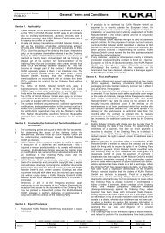
<strong>KR</strong> <strong>16</strong> <strong>arc</strong> <strong>HW</strong>, <strong>KR</strong> <strong>16</strong> <strong>L8</strong> <strong>arc</strong> <strong>HW</strong>• Hollow-shaft wrist• Arm• Link arm• Rotating column• Base frame• Electrical installationsFig. 3-2: Main assemblies of the manipulator1 Hollow-shaft wrist 4 Base frame2 Arm 5 Rotating column3 Electrical installations 6 Link armHollow-shaftwristArmLink armRotating columnThe robot variants <strong>KR</strong> <strong>16</strong> <strong>arc</strong> <strong>HW</strong> and <strong>KR</strong> <strong>16</strong> <strong>L8</strong> <strong>arc</strong> <strong>HW</strong> are equipped with a2-axis hollow-shaft wrist. The wrist contains axes 5 and 6. The motors of axes5 and 6 are incorporated in this assembly. Both axes are driven via toothedbelts and gear units. The design enables the fluid supply to be routed directlythrough the center of axis 6 to the application.For attaching end effectors (tools), the in-line wrist has a mounting flange.The arm is the link between the hollow-shaft wrist and the link arm. It housesthe motors of wrist axes 3 and 4. The arm is driven by the motor of axis 3. Themaximum permissible swivel angle is mechanically limited by a stop for eachdirection, plus and minus. The associated buffers are attached to the link arm.The entire drive unit of axis 4 is also integrated inside the arm. In addition, thecable harness for the wrist axes A 5 and A 6 is installed under a cover. Fasteningfacilities are provided for the welding application equipment on the rearof the arm. The fluid supply to the tool is routed axially through the arm.The link arm is the assembly located between the arm and the rotating column.It consists of the link arm body with the buffers.The rotating column houses the motors of axes 1 and 2. The rotational motionof axis 1 is performed by the rotating column. This is screwed to the baseframe via the gear unit of axis 1 and is driven by a motor in the rotating column.The link arm is also mounted in the rotating column.10 / 79 Issued: 19.04.2013 Version: Spez <strong>KR</strong> <strong>16</strong> <strong>arc</strong> <strong>HW</strong> V6 en (PDF)