You also want an ePaper? Increase the reach of your titles
YUMPU automatically turns print PDFs into web optimized ePapers that Google loves.
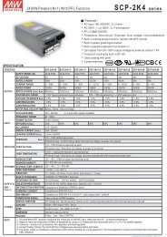
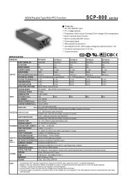
PreliminaryThe Fifth Generation, Ultra Small Size, Isolated DC-DC ConverterBSV-H22A SeriesBSV-H series is a small size(23.0x27.0x4mm size) and light weight(4.0g) step-down DC-DC converter, which hasachieved 22A. Since it can correspond from ultra low output voltage of 0.6V, and set accuracy of output voltage isunder ±1%, it can be used for the latest DSP, ASIC and FPGA applications. Due to high efficiency and high-speedresponse by synchronous rectification circuit technology, saving space by no external components, and with SMDpackage etc. an excellent performance beyond our common sense has been achieved.-Ultra Small Size 23x27mm-Low Profile 4.0mm-High-Speed Load Response-Output Voltage Accuracy ±1%-Ultra High Efficiency-Built in Over-Current Protection-Under Voltage Lock Out-Remote ON/OFF Control-Adjustable Output Voltage-Surface Mount Package (SMD)-External Capacitors not required-Heat Sink not required-Non-Isolated Type-Operating Temp. Range –40°C to +85°C(Temp. Derating required)-RoHS Compliance Table 1ModelInput VOutput VOutput I Output ADJNoiseEfficiencyVdcVdcAVdcmVpp(typ.)%(typ.)BSV-1.5S22R0H 3.0 to 5.5 1.5 0 to 22 0.6 to 1.5 30 87Note1 : The value of ripple and noise and efficiency is the one at input voltage (5V) and rating load.Note2 : Measurements of ripple noise is performed at BW=20MHz, with an additional multilayer ceramic capacitor of 47F tothe input and 22F to the output.Note3 : Depending on the ambient air temperature conditions, air flow is required.Table2Rating Input Voltage/ Range Refer to Table 1Rating Output Voltage +1.5V±1%(Trim Pin at open)Adjustable Output VoltageRange0.6~1.5VLine Regulation 0.5% typ. (Rating output, for the regulation of input voltage range on table 1)Load Regulation 0.5% typ. (Rating input/output voltage, for the regulation of load 0-100%)Temperature Coefficient ±0.02%/°C typ. (Input/output rating, for the regulation of operating temp. range -40°C to +50°C)Ripple NoiseRefer to Table 1 (Input/output rating, normal temperature and Bw=20MHz)Efficiency 87% typ. (Input/output rating, normal temperature. Refer to table 1)Turn-On Transient0.5ms typ. (Resistance load)Max. Output Capacitance 4700F max.Over-Current ProtectionOperates at 105% or more rating load current, auto recovery type. Avoid long time short-circuitcondition.Over-Voltage Protection NoneUnder Voltage Lock Out AvailableRemote On/Off ControlBetween 10pin (ON/OFF) and –6, 9pin (GND): output goes ON when in open, output goesOFF when in shortStandby Current0.2mA typ.P-Good SignalAt normal output: high, at output decrease: low, (This terminal is open-drain.)Remote SensingAvailableOperating Temp. Range -40°C to +85°C (Refer to thermal derating graph)Storage Temp. Range -40°C to +85°CHumidity Range20%-95%R.H. max. (Max. wet bulb 35°C, non-condensing)Storage ConditionFor the converter before being mounted, store at 30°C/60% R.H. or belowCooling ConditionRefer to thermal derating graphVibration5-10Hz All amplitude 10mm, 10-55Hz acceleration 2G (1 hour in each of 3 orthogonal axes)ShockAcceleration 20G (3 directions, 3 times each, total : 18 times), Shocking time 11±5msWeight4.0g typ.OutlineSMD type W=23.0 L=27.0 H=4.0 typ. (mm) (For detail dimensions refer to the outline)*The above specification is provided with rating value, unless otherwise specifiedDC-DC ConverterBDD20080618
The Fifth Generation, Ultra Small Size, Isolated DC-DC ConverterBSV-H22A Series1- Application RangeThis specifications is applied to the direct current input and non-isolated type DC/DC converter, BSV-1.5S22R0H.2- Model and ratingModel Rating Input Voltage Rating Output Package type NoteBSV-1.5S22R0H DC5.0V 1.5V, 22.0A SMDWhen the condition is not described in this specifications, it will be that the input is the rated input and the rated outputand the ambient temperature is 25°C±5°C3- Environmental Condition3-1 Temperature rangeAt Operating : -40°C to +85°C (Load derating from 55°C is required, only when mounting on a both sided PCB of 100 X100mm and thickness 1.6mm.)At Storage : −40°C to 85°C3-2 Humidity RangeAt Operating : 20~95%RH (Maximum wet bulb temperature is 35°C, and not dew condensation.)At Storage : The same as aboveNote). Before mounting, it is different from the above mentioned condition.Please refer to the section of “Mounting condition” for details.4.Specification and StandardThis product is a lead free products.4-1. Input characteristicItem Specification and Standard TermsInput voltage+3.0 to 5.5V (Ratings : 5.0V)Input current 7.60A typ. At rating input and rating outputStanby current 0.2mA typ. Vin=5.0V, Short between On/Off Pin – GND PinDC-DC Converter2BDD20080618
The Fifth Generation, Ultra Small Size, Isolated DC-DC ConverterBSV-H22A Series4-2 Output characteristic and attached functionItem Specification and standard TermsOutput voltage 1.5VOutput voltage set accuracy1.5V±1.0% (±0.015V)Adjustable Output Voltage Range 0.6V to 1.5V Depending on external resistanceOutput current 0 to 22A Derating requiredLine Regulation 0.5% typ. (1.0% max) For regulation of 3.0 to 5.5V inputLoad Regulation 0.5% typ. (1.0% max) For regulation of 0 to 22A loadTemperature Coefficient ±0.02%/°C typ. For coefficient of –40 to + 35°CEfficiency87% typ.Ripple Noise 30mVp-p typ. 100mVp-p max. Bw=20MHzOver-Current ProtectionOperates at 105% or more rating loadcurrent, auto recovery type.Starts and it returns by 50% of ratingsthe load when the start and O.C. arereleased.Over-Voltage ProtectionUnder Voltage Lock OutNoneAvailableStart up voltage : 2.8V±0.2VShut down voltage : 2.7V±0.2VStarting up at 3V or moreON/OFF ControlOpen or High (2V or more) – ONShort or Low (0.8V or less) – OffP-Good low level voltage 0.4V max Sink current : 14mA maxTurn-On Transient 0.5ms typ. Resistance loadMax. Output Capacitance4700F maxNote 1) With the measurement circuit of 4-3.Note 2) Measured by the following conditions without any notice ;Input voltage : 5V, Output voltage : 1.5V, Output Current : 22A, (Resistance load), Ambient temperature : 25°C±5°C4-3 Measurement Circuit DC-DC Converter3BDD20080618
The Fifth Generation, Ultra Small Size, Isolated DC-DC ConverterBSV-H22A Series5. Block DiagramL1+Vin1POWER IC+Vout5P-Good2PGVfb+Sense4controlTrim8on/off10on/offVref-Sense7GND9GND66. Thermal DeratingSet this products in a place where good convection is ensured. And also be sure to mount on a board, when using.This product has been designed to radiate by utilizing the mounted board. So make the line to connect to the converter aswide as possible. The radiation from GND is especially big, so make the GND line wide.The derating curve below is a data when mounted on a double-side board of copper foil thickness 35m, copper foil area100x100mm (both sides) and thickness of the board 1.6mm. The radiation characteristics will change depending on thewiring, so please refer to the data.The thermal characteristics for this converter will be largely influenced by the mounted board and the ambient condition. Forthis reason, finally mount the converter into the device that will be actually mounted. And when it is operated at the maximumambient temperature of the equipment, be sure that the temperature of the board surface does not exceed 100°C.2520Vin=5.0VVout=1.5VOutput Current A151050m/s0.5m/s1.0m/s2.0m/sElemental converter0m/s0-40 -30 -20 -10 0 10 20 30 40 50 60 70 80Ambient Temperature (°C)Copper foil area 100 x 100mm The derating curve of substrate is mountedDC-DC Converter4BDD20080618
The Fifth Generation, Ultra Small Size, Isolated DC-DC ConverterBSV-H22A Series7. Outline and Pin Function7-1. Shape, Outline and Package (SMD type)(2.0)1.4Company logo105.527.020.014.512.016.77.491.4871.47.4614.3Pi Functionn 1 +Vin2 P-Good3 NC4 +Sense5 +Vout6 GND7 -Sense8 Trim9 GND10 On/Off- Dimensions : mmModelnameA21.023.0- Tolerances unless otherwise specified : ±0.5- Weight = 4.0G typ- The adsorption position uses left chart A point- It displays “V1.5S22” to the model display to the product1pin mark11.4 2 3 4 1.457.43.01.47.48.512.014.520.0Lot no.- Lot No. is filled in on 5 pin side.Mark : End of A.D.The manufacturing months (10,11,12,months is O, N, D)1.04.0 max.Lot of the months (The first lot is filled in nothing.)- Flapping of pin 0.2mm max (Floatage of pin when putting it ona horizontal plane)Note) Be sure to pick up at point A shown in the outlinewhen mounting by an automated machine. Avoidpick up at the component(IC) placed in the center ofthe board.7-2. Recommended Pad Layout1.75.520.014.512.07.71.71.77.7Note) Do not wire a pattern right under the converterA B A A B(first layer). Since this converter hasadopted a normal through-hole board, if there20.825.6is a pinhole in the resist, it may become a2.4BAA ABproblem.7.73.08.51.71.71.712.014.520.007.7DC-DC Converter5BDD20080618
The Fifth Generation, Ultra Small Size, Isolated DC-DC ConverterBSV-H22A Series8. Standard Connection Circuit Diagram8-1. Standard connection circuit+Vin+C1+VinP-Good2On/Off1 510BSV-1.5S22R0H48+Vout+SenseTrimR1C2LoadGND6,97-SenseSW Open=OnShort =OffR1:Vout Down Set ResistorC1 : 47µF x 2C2 : 22µFNote 1) It is a prerequisite for this product to be mounted onto a board, thereby heat relation is done. 70% or more of theheat radiation is done from the GND pin(6, 9pin) and the rest is done from the +Vin pin and +Vout pin. Take spaceof the pattern as much as possible and design the board to make radiation easy. (Please use that surfacetemperature of converter’s PCB will not exceed 100°C.)Note 2) The third pin is check pin when it manufactures. Please install land for the converter fixation and fix on the board.Please do not connect this land with the GND line or +Vin line, etc.Note 3) When not using the On/Off control, keep the On/Off pin open.Note 4) When not adjusting the output, keep the trim pin open.Note 5) GND pin (6, 9pin) is connect inside, however to secure the performance, use it with the 2 pins connected to theGND line.Note 6) Be sure to connect the sense pin and output pin on the board. Unless the sense pin is connected, there is apossibility that a higher voltage than the rating voltage may be output.Note 7) Do not wire a pattern right under the converter (first layer). For other layers wiring a pattern will be no problem.Recommended CapacitorC1=47F x 2C2=2.2F ~200FC1 : It is unnecessary if impedance of the power supply on the input side is low enough and the power supply on inputside is connected by the enough thick and short line, however, it is necessary if the impedance is high. Use oneswith low ESR such as organic semiconductor solid capacitor, multilayer ceramic capacitor.C2 : The converter will operate without C2 because the output capacitor has built in, however, it is necessary to satisfywith the electric characteristic (Ripple Noise). The connecting to the load side will make noise decrease. Use amultilayer ceramic capacitor.DC-DC Converter6BDD20080618
The Fifth Generation, Ultra Small Size, Isolated DC-DC ConverterBSV-H22A Series8-2. ON/OFF ControlBy using the ON/OFF control function, ON/OFF of the output without connecting and disconnecting the input can be controlled.ON/OFF Pin (9pin) has been connected with +Vin terminal internally by the resistance of 22k.When not using the ON/OFF control, keep the ON/OFF pin open.Between ON/OFF pin (10pin) and GND (9pin)Open: Output=ONShort (0 to 0.8V 0.3mA max.) : Output=OFF+Vin122k or10GND6,98-3. Adjusting Output VoltageWhen using at 1.5V without adjusting output voltage, keep Trim pin (8pin) open. By connecting a resistor between Trim (8pin)and –Sense pin (7pin) , the output voltage can be adjusted within the range of 0.6-1.5V. Connect –Sense pin to GND (6pin).When adjusting the output voltage, place the Rx close to the converter and make the wiring of Rx as short as possible. If theTrim pin catches noise, malfunction may occur.To calculate the external resistance, please refer to the equation below. After calculating the external resistance, pleasecheck the output voltage and adjust the resistance value.To set within the range of 0.6V-1.5VR2×VoutRx =I1×R2 - VoutR1( )R1=24k ohm, R2=52.6k ohm, I1=0.0286mA, Vout=Requested output voltage (V)+Vout5Ex.)DesiredOutput VoltageVout (V)RxCalculated Value(k ohm)1.5 Open1.2 183.391.0 80.290.8 35.740.6 10.90I1R2R14+SenseTrim8-Sense7RxGND6,9DC-DC Converter7BDD20080618
The Fifth Generation, Ultra Small Size, Isolated DC-DC ConverterBSV-H22A Series8-4. Sensing functionAn excellent load regulation characteristic can be obtained by using the sensing function on the load side. Enoughattention is required for wiring because the sensing line is a part of the feedback loop, and it is very sensitive. Please wire+Sense and –Sense close together to the load.Please connect the +Vout Pin and +Sense Pin, -Vout Pin and –Sense Pin respectively on the PCB when not using thesensing function.8-5. P-Good FunctionBy utilizing this P-Good pin, the output condition of the converter can be obtained.This terminal is open-drain. If using P-Good function, please use P-Good terminalconnecting the resistor outside and pulling-up to the input voltage.It will be open by|Output voltage-Set voltage|0.2V typ.However, under the conditions written below, even if the output voltage iswithin this range, it may become low.- When the input voltage is below 3V- When the output current is at over-current state.- When the IC temperature is above 100°C+Vin147KP-Good2GND 5,8DC-DC Converter8BDD20080618
The Fifth Generation, Ultra Small Size, Isolated DC-DC ConverterBSV-H22A Series9. To prevent reverse input voltage protection(Ex.)This product is a non-isolated type DC-DC converter thatsteps-down from (+) to (+).If the input voltage reversed is connected by mistake, it willbe damaged.If there is a possibility of reverse connection, please adda protection as shown in the right figure. The right figure isan example using fuse and diode.+VinFUSED1+Vin1+Vout5P-Good24BSV-1.5S22R0H +Senseon/offTrim810-Sense76,9GNDLoad10. Over-Voltage Protection Diagram (Ex.)This product does not have a built-in over-voltage protection.If the switching element in this converter is damaged in shortmode, DC input voltage will go out as output.To avoid damage at over-voltage mode, in advance,please add the input interrupting circuit as the right figure.+VinFUSESCR+Vin1+Vout5P-Good24BSV-1.5S22R0H +SenseTrimon/off108-Sense76,9Over-VoltagedetectioncircuitLoadNote 1. When it is damaged at over-voltage mode,ON/OFF control will not operate.Note 2. When having ON/OFF function on the supplyingpower side, this circuit can be used.Note 3. Be sure that the DC power supply on the supplyingside has the capacity to cut the fuse.GNDDC-DC Converter9BDD20080618
The Fifth Generation, Ultra Small Size, Isolated DC-DC ConverterBSV-H22A Series11. Soldering ConditionsPlease conduct by the condition as below regarding the soldering temperature and time and storage before mounting.11-1. Reflow methodPre-heating temp.: 150-180°C, within 60 sec max. (Refer to the figure below)Peak heading temp.: 250°C max.220°C or more, within 60 sec max.Reflow: twiceNote 1. Do not give shock at reflow because components which compose the converter may move.Note 2. After mounting the converter on PCB, please do not reflow again turning the PCB over.Note 3. This converter cannot be soldered by flow.11-2. About storage before being mountedWhen you open dry packing, storage conditions before being mounted should be 30°C/60% RH or below. Moreover, baking(125°C±5°C, 12H) is needed before the reflow when it is one year while dry packed and dry packing is opened with 30°C/60%RH above 168 hours.After mounting, it depends on the environmental condition.Temp.Temp. regulation point is thecomponent surface temp.2/sec. max.Peak:250max.2201801 to 4/sec.1502.3/sec. max.60sec. max.60sec. max.Time12. Vibration and shock testVibration : 5~10 Hz All amplitudes 10mm, 10~55Hz Acceleration 2G (Three direction, for one hour each)Shock : Acceleration 20G (Three direction, three times each)Shocking time 11±5msDC-DC Converter10BDD20080618
The Fifth Generation, Ultra Small Size, Isolated DC-DC ConverterBSV-H22A Series13. Cleaning ConditionsThis product can not be washed whole. No-clean solder paste is recommended for this product.14. PrecautionsFor customer’s safety, when using this product, please refer to the specification and please use keeping the followingprecautions surely.- This product is for being used in general electric equipments (business equipments, telecommunication equipments andmeasurement equipment).Can not be used in medical equipments, nuclear equipments and trains which would affect lives or properties directly by thefailure of this product.Be sure to contact our sales when using in besides general use.- For this product parallel and series operation are not possible.- For mounting this product, please do not use connector of socket. The performance may not be fulfilled due to the effect ofcontacting resistor.Mount to print board by soldering.- This product has a built-in over-current, short protection, but long time short circuit will cause failure, so please avoid it.- There is possibility of damage when used under electric conditions and environmental conditions such as temperature thatare out of the standards.Be sure to be use within the standards.- Do not store in a place where corrodible gas may be generated or a dusty place.- There is possibility of damage by static. When the worker has electrified static, electrical discharge should be done and theworking on the table so grounded may be recommended.- This product does not have a built-in fuse. Connect a fuse to the +input line for protection when over-current flows into inputat abnormal. Please be sure that the supplying power has the capacity to fuse the fuse.- This product does not have a built-in over-voltage protection. When over-voltage occurs due to the abnormality in themodule, there is a mode that input voltage comes out at it is, and may cause smoke and ignition. To prevent this, be sure toadd over-voltage protection.- No test result certificate attached to this product.15. GuaranteeThe guaranteed term of this product is one year. When occurring any failure mode by the cause of our design and productionin this guaranteed term, we will repair the failure product or replace to the good product by free of charge.However, when being remodeled inside etc., we shall not guarantee it.The range of the guarantee for this product is the one of this products concerned.DC-DC Converter11BDD20080618