R&S FSV-K82/-K83 Firmware Options ... - Rohde & Schwarz
R&S FSV-K82/-K83 Firmware Options ... - Rohde & Schwarz
R&S FSV-K82/-K83 Firmware Options ... - Rohde & Schwarz

You also want an ePaper? Increase the reach of your titles
YUMPU automatically turns print PDFs into web optimized ePapers that Google loves.
R&S ® <strong>FSV</strong>-<strong>K82</strong>/-<strong>K83</strong><strong>Firmware</strong> <strong>Options</strong> CDMA2000AnalysisOperating Manual(;×7À2)1173.0750.02 ─ 07Test & MeasurementOperating Manual
R&S ® <strong>FSV</strong>-<strong>K82</strong>/-<strong>K83</strong>ContentsContents1 Preface....................................................................................................51.1 Documentation Overview.............................................................................................51.2 Conventions Used in the Documentation...................................................................71.3 How to Use the Help System........................................................................................82 Introduction..........................................................................................103 Test Setup for Base Station or Mobile Station Tests........................114 Measurement Examples for the CDMA2000 BTS Analysis (option<strong>K82</strong>).......................................................................................................134.1 Test Setup for Base Station Tests.............................................................................134.2 Measuring the Signal Channel Power.......................................................................154.3 Measuring the Spectrum Emission Mask.................................................................164.4 Measuring the Relative Code Domain Power and Frequency Error.......................174.5 Measuring the Triggered Relative Code Domain Power.........................................194.6 Measuring the Composite EVM.................................................................................204.7 Measuring the Peak Code Domain Error and the RHO Factor................................225 Measurement Examples for the CDMA2000 MS Analysis (option<strong>K83</strong>).......................................................................................................245.1 Test Setup for Base Station or Mobile Station Tests...............................................245.2 Measuring the Signal Channel Power.......................................................................265.3 Measuring the Spectrum Emission Mask.................................................................275.4 Measuring the Relative Code Domain Power and Frequency Error.......................285.5 Measuring the Triggered Relative Code Domain Power.........................................305.6 Measuring the Composite EVM.................................................................................315.7 Measuring the Peak Code Domain Error and the RHO Factor................................336 Instrument Functions of the CDMA2000 Analysis............................356.1 Measurements and Result Displays..........................................................................376.2 Menu and Softkey Description for CDA Measurements..........................................556.3 Softkeys and Menus for RF Measurements (<strong>K82</strong>)....................................................956.4 Further Information...................................................................................................1477 Remote Commands of the CDMA2000 BTS Analysis.....................174Operating Manual 1173.0750.02 ─ 073
R&S ® <strong>FSV</strong>-<strong>K82</strong>/-<strong>K83</strong>Contents7.1 Notation......................................................................................................................1757.2 CALCulate Subsystem..............................................................................................1777.3 CONFigure Subsystem.............................................................................................2177.4 DISPlay Subsystem...................................................................................................2267.5 INSTrument Subsystem............................................................................................2337.6 SENSe Subsystem....................................................................................................2347.7 STATus subsystem...................................................................................................2777.8 TRACe Subsystem....................................................................................................2787.9 Other Commands Referenced in this Manual........................................................2868 Status Reporting System of the CDMA2000 BTS Analysis (option<strong>K82</strong>).....................................................................................................3009 Glossary..............................................................................................30110 Appendix.............................................................................................302List of Commands..............................................................................305Index....................................................................................................311Operating Manual 1173.0750.02 ─ 074
R&S ® <strong>FSV</strong>-<strong>K82</strong>/-<strong>K83</strong>PrefaceDocumentation Overview1 Preface1.1 Documentation OverviewThe user documentation for the R&S <strong>FSV</strong> is divided as follows:●●●●●Quick Start GuideOperating Manuals for base unit and optionsService ManualOnline HelpRelease NotesQuick Start GuideThis manual is delivered with the instrument in printed form and in PDF format on theCD. It provides the information needed to set up and start working with the instrument.Basic operations and basic measurements are described. Also a brief introduction toremote control is given. The manual includes general information (e.g. Safety Instructions)and the following chapters:Chapter 1Chapter 2Chapter 3Chapter 4Chapter 5Chapter 6Chapter 7AppendixAppendixIntroduction, General informationFront and Rear PanelPreparing for Use<strong>Firmware</strong> Update and Installation of <strong>Firmware</strong> <strong>Options</strong>Basic OperationsBasic Measurement ExamplesBrief Introduction to Remote ControlPrinter InterfaceLAN InterfaceOperating ManualsThe Operating Manuals are a supplement to the Quick Start Guide. Operating Manualsare provided for the base unit and each additional (software) option.The Operating Manual for the base unit provides basic information on operating theR&S <strong>FSV</strong> in general, and the "Spectrum" mode in particular. Furthermore, the softwareoptions that enhance the basic functionality for various measurement modes are describedhere. The set of measurement examples in the Quick Start Guide is expanded bymore advanced measurement examples. In addition to the brief introduction to remotecontrol in the Quick Start Guide, a description of the basic analyzer commands and programmingexamples is given. Information on maintenance, instrument interfaces anderror messages is also provided.Operating Manual 1173.0750.02 ─ 075
R&S ® <strong>FSV</strong>-<strong>K82</strong>/-<strong>K83</strong>PrefaceDocumentation OverviewIn the individual option manuals, the specific instrument functions of the option aredescribed in detail. For additional information on default settings and parameters, referto the data sheets. Basic information on operating the R&S <strong>FSV</strong> is not included in theoption manuals.The following Operating Manuals are available for the R&S <strong>FSV</strong>:●●●●●●●●●●●●●●●R&S <strong>FSV</strong> base unit; in addition:– R&S <strong>FSV</strong>-K9 Power Sensor Support– R&S <strong>FSV</strong>-K14 Spectrogram MeasurementR&S <strong>FSV</strong>-K7 Analog Demodulation and R&S <strong>FSV</strong>-K7S FM Stereo MeasurementsR&S <strong>FSV</strong>-K10 GSM/EDGE MeasurementR&S <strong>FSV</strong>-K30 Noise Figure MeasurementR&S <strong>FSV</strong>-K40 Phase Noise MeasurementR&S <strong>FSV</strong>-K70 Vector Signal Analysis Operating ManualR&S <strong>FSV</strong>-K70 Vector Signal Analysis Getting Started (First measurements)R&S <strong>FSV</strong>-K72 3GPP FDD BTS AnalysisR&S <strong>FSV</strong>-K73 3GPP FDD UE AnalysisR&S <strong>FSV</strong>-K76/77 3GPP TD-SCDMA BTS/UE MeasurementR&S <strong>FSV</strong>-<strong>K82</strong>/83 CDMA2000 BTS/MS AnalysisR&S <strong>FSV</strong>-K84/85 1xEV-DO BTS/MS AnalysisR&S <strong>FSV</strong>-K91 WLAN IEEE 802.11a/b/g/j/nR&S <strong>FSV</strong>-K93 WiMAX IEEE 802.16 OFDM/OFDMA AnalysisR&S <strong>FSV</strong>-K100/K104 EUTRA / LTE Downlink Measurement ApplicationR&S <strong>FSV</strong>-K101/K105 EUTRA / LTE Uplink Measurement ApplicationThese manuals are available in PDF format on the CD delivered with the instrument. Theprinted manual can be ordered from <strong>Rohde</strong> & <strong>Schwarz</strong> GmbH & Co. KG.Service ManualThis manual is available in PDF format on the CD delivered with the instrument. Itdescribes how to check compliance with rated specifications, instrument function, repair,troubleshooting and fault elimination. It contains all information required for repairing theR&S <strong>FSV</strong> by replacing modules. The manual includes the following chapters:Chapter 1Chapter 2Chapter 3Chapter 4Chapter 5Performance TestAdjustmentRepairSoftware Update / Installing <strong>Options</strong>DocumentsOnline HelpThe online help contains context-specific help on operating the R&S <strong>FSV</strong> and all availableoptions. It describes both manual and remote operation. The online help is installed onOperating Manual 1173.0750.02 ─ 076
R&S ® <strong>FSV</strong>-<strong>K82</strong>/-<strong>K83</strong>PrefaceConventions Used in the Documentationthe R&S <strong>FSV</strong> by default, and is also available as an executable .chm file on the CDdelivered with the instrument.Release NotesThe release notes describe the installation of the firmware, new and modified functions,eliminated problems, and last minute changes to the documentation. The correspondingfirmware version is indicated on the title page of the release notes. The current releasenotes are provided in the Internet.1.2 Conventions Used in the Documentation1.2.1 Typographical ConventionsThe following text markers are used throughout this documentation:Convention"Graphical user interface elements"KEYSFile names, commands,program codeInputLinks"References"DescriptionAll names of graphical user interface elements on the screen, such as dialogboxes, menus, options, buttons, and softkeys are enclosed by quotationmarks.Key names are written in capital letters.File names, commands, coding samples and screen output are distinguishedby their font.Input to be entered by the user is displayed in italics.Links that you can click are displayed in blue font.References to other parts of the documentation are enclosed by quotationmarks.1.2.2 Conventions for Procedure DescriptionsWhen describing how to operate the instrument, several alternative methods may beavailable to perform the same task. In this case, the procedure using the touchscreen isdescribed. Any elements that can be activated by touching can also be clicked using anadditionally connected mouse. The alternative procedure using the keys on the instrumentor the on-screen keyboard is only described if it deviates from the standard operatingprocedures.The term "select" may refer to any of the described methods, i.e. using a finger on thetouchscreen, a mouse pointer in the display, or a key on the instrument or on a keyboard.Operating Manual 1173.0750.02 ─ 077
R&S ® <strong>FSV</strong>-<strong>K82</strong>/-<strong>K83</strong>PrefaceHow to Use the Help System1.3 How to Use the Help SystemCalling context-sensitive and general help► To display the general help dialog box, press the HELP key on the front panel.The help dialog box "View" tab is displayed. A topic containing information about thecurrent menu or the currently opened dialog box and its function is displayed.For standard Windows dialog boxes (e.g. File Properties, Print dialog etc.), no contextsensitivehelp is available.► If the help is already displayed, press the softkey for which you want to display help.A topic containing information about the softkey and its function is displayed.If a softkey opens a submenu and you press the softkey a second time, the submenu ofthe softkey is displayed.Contents of the help dialog boxThe help dialog box contains four tabs:● "Contents" - contains a table of help contents● "View" - contains a specific help topic● "Index" - contains index entries to search for help topics● "Zoom" - contains zoom functions for the help displayTo change between these tabs, press the tab on the touchscreen.Navigating in the table of contents●●●To move through the displayed contents entries, use the UP ARROW and DOWNARROW keys. Entries that contain further entries are marked with a plus sign.To display a help topic, press the ENTER key. The "View" tab with the correspondinghelp topic is displayed.To change to the next tab, press the tab on the touchscreen.Navigating in the help topics●●To scroll through a page, use the rotary knob or the UP ARROW and DOWNARROW keys.To jump to the linked topic, press the link text on the touchscreen.Searching for a topic1. Change to the "Index" tab.Operating Manual 1173.0750.02 ─ 078
R&S ® <strong>FSV</strong>-<strong>K82</strong>/-<strong>K83</strong>PrefaceHow to Use the Help System2. Enter the first characters of the topic you are interested in. The entries starting withthese characters are displayed.3. Change the focus by pressing the ENTER key.4. Select the suitable keyword by using the UP ARROW or DOWN ARROW keys or therotary knob.5. Press the ENTER key to display the help topic.The "View" tab with the corresponding help topic is displayed.Changing the zoom1. Change to the "Zoom" tab.2. Set the zoom using the rotary knob. Four settings are available: 1-4. The smallestsize is selected by number 1, the largest size is selected by number 4.Closing the help window► Press the ESC key or a function key on the front panel.Operating Manual 1173.0750.02 ─ 079
R&S ® <strong>FSV</strong>-<strong>K82</strong>/-<strong>K83</strong>Introduction2 IntroductionOverview of <strong>Firmware</strong> <strong>Options</strong> R&S <strong>FSV</strong>-<strong>K82</strong> and <strong>K83</strong>This section contains all information required for operation of an R&S <strong>FSV</strong> equipped withApplication <strong>Firmware</strong> R&S <strong>FSV</strong>-<strong>K82</strong> or <strong>K83</strong>. It covers operation via menus and theremote control commands for the CDMA2000 base station (BTS) or mobile station (MS)analyzer.This part of the documentation consists of the following chapters:● chapter 3, "Test Setup for Base Station or Mobile Station Tests", on page 11Describes the measurement setup for base station or mobile station tests.●●chapter 4, "Measurement Examples for the CDMA2000 BTS Analysis (option <strong>K82</strong>)",on page 13Explains some basic 1xEV-DO base station tests.chapter 5, "Measurement Examples for the CDMA2000 MS Analysis (option <strong>K83</strong>)",on page 24Explains some basic 1xEV-DO mobile station tests.● chapter 6, "Instrument Functions of the CDMA2000 Analysis", on page 35Describes the instrument functions of CDMA2000 Analysis.● chapter 7, "Remote Commands of the CDMA2000 BTS Analysis", on page 174Describes all remote control commands defined for the code domain measurement.An alphabetic list of all remote control commands and a table of softkeys with theassignment of commands are provided at the end of this chapter.●chapter 8, "Status Reporting System of the CDMA2000 BTS Analysis (option <strong>K82</strong>)",on page 300Contains device-specific error messages for R&S <strong>FSV</strong>-<strong>K82</strong>.● chapter 9, "Glossary", on page 301Contains an explanation of terms and abbreviations related to the code domainanalysis.● chapter 10, "Appendix", on page 302This part of the documentation includes only functions of the Application <strong>Firmware</strong>R&S <strong>FSV</strong>-<strong>K82</strong> and <strong>K83</strong>. For all other descriptions, please refer to the description of thebase unit.Operating Manual 1173.0750.02 ─ 0710
R&S ® <strong>FSV</strong>-<strong>K82</strong>/-<strong>K83</strong>Test Setup for Base Station or Mobile Station Tests3 Test Setup for Base Station or Mobile StationTestsThis section describes the default settings of the R&S <strong>FSV</strong>, if it is used as a CDMA2000base or mobile station tester. Before starting the measurements, the R&S <strong>FSV</strong> has to beconfigured correctly and supplied with power as described in the Quick Start Guide,"Preparing For Use". Furthermore, the application firmware of the R&S <strong>FSV</strong>-<strong>K82</strong> (basestation) or -<strong>K83</strong> (mobile station) must be enabled. Installation and enabling of the applicationfirmware are described in the Quick Start Guide.Risk of instrument damage during operationAn unsuitable operating site or test setup can cause damage to the instrument and toconnected devices. Ensure the following operating conditions before you switch on theinstrument:●●●●●●All fan openings are unobstructed and the airflow perforations are unimpeded. Theminimum distance from the wall is 10 cm.The instrument is dry and shows no sign of condensation.The instrument is positioned as described in the following sections.The ambient temperature does not exceed the range specified in the data sheet.Signal levels at the input connectors are all within the specified ranges.Signal outputs are correctly connected and are not overloaded.Connect the antenna output (or TX output) of the base station/mobile station to the RFinput of the R&S <strong>FSV</strong>. Use a power attenuator exhibiting suitable attenuation.TX signalRFINPUT1 2ABC DEF 3 GHI4 5 67 8 9STU ÜVW XYZ0 . -RCL S CMThe following values for external attenuation are recommended to ensure that the RFinput of the analyzer is protected and the sensitivity of the unit is not reduced too much:Operating Manual 1173.0750.02 ─ 0711
R&S ® <strong>FSV</strong>-<strong>K82</strong>/-<strong>K83</strong>Test Setup for Base Station or Mobile Station TestsMaximum Power≥ 55 to 60 dBm≥ 50 to 55 dBm≥ 45 to 50 dBm≥ 40 to 45 dBm≥ 35 to 40 dBm≥ 30 to 35 dBm≥ 25 to 30 dBm≥ 20 to 25 dBm≤ 20 dBmRecommended external attenuation35 to 40 dB30 to 35 dB25 to 30 dB20 to 25 dB15 to 20 dB10 to 15 dB0 to 10 dB0 to 5 dB0 dB●●●For signal measurements at the output of two-port networks, connect the referencefrequency of the signal source to the rear reference input of the analyzer.The R&S <strong>FSV</strong> must be operated with an external frequency reference to ensure thatthe error limits of the CDMA2000 specification for frequency measurements on basestations/mobile stations are met. A rubidium frequency standard can be used as areference source for example.If the base station/mobile station has a trigger output, connect the trigger output ofthe base station/mobile station to the rear trigger input of the analyzer (EXT TRIGGATE).Presettings●●●●●●●Enter the external attenuation.Enter the reference level.Enter the center frequency.Set the trigger.If used, enable the external reference.Select the standard and the desired measurement.Set the PN offset.Operating Manual 1173.0750.02 ─ 0712
R&S ® <strong>FSV</strong>-<strong>K82</strong>/-<strong>K83</strong>Measurement Examples for the CDMA2000 BTS Analysis (option <strong>K82</strong>)Test Setup for Base Station Tests4 Measurement Examples for the CDMA2000BTS Analysis (option <strong>K82</strong>)This section explains basic CDMA2000 base station tests by means of a setup with asignal generator, e.g. an R&S SMU. It describes how operating and measurement errorscan be avoided using correct settings. The measurements are performed with anR&S <strong>FSV</strong> equipped with the CDMA2000 BTS Analysis option (<strong>K82</strong>).The following measurements are described:● chapter 4.2, "Measuring the Signal Channel Power", on page 15● chapter 4.3, "Measuring the Spectrum Emission Mask", on page 16●●chapter 4.4, "Measuring the Relative Code Domain Power and Frequency Error",on page 17chapter 4.5, "Measuring the Triggered Relative Code Domain Power",on page 19● chapter 4.6, "Measuring the Composite EVM", on page 20●chapter 4.7, "Measuring the Peak Code Domain Error and the RHO Factor",on page 22As the CDMA2000 BTS Analysis option also supports the CDMA2000 Standard, theexamples are performed on an CDMA2000 signal.General Test SetupThe measurements are performed with the following units and accessories:●●●●An R&S <strong>FSV</strong> equipped with the CDMA2000 BTS Analysis option.R&S SMU signal generator equipped with option SMU-B9/B10/B11 baseband generatorand SMUK46 CDMA2000 incl. 1xEVDV.1 coaxial cable, 50 Ω, approximately 1 m, N connector2 coaxial cables, 50 Ω, approximately 1 m, BNC connector4.1 Test Setup for Base Station TestsThis section describes the default settings of the R&S <strong>FSV</strong>, if it is used as a CDMA2000base station tester. Before starting the measurements, the R&S <strong>FSV</strong> has to be configuredcorrectly and supplied with power as described in the Quick Start Guide, "Preparing ForUse". Furthermore, the application firmware of the R&S <strong>FSV</strong>-<strong>K82</strong> must be enabled.Installation and enabling of the application firmware are described in the Quick StartGuide, chapter 3.Operating Manual 1173.0750.02 ─ 0713
R&S ® <strong>FSV</strong>-<strong>K82</strong>/-<strong>K83</strong>Measurement Examples for the CDMA2000 BTS Analysis (option <strong>K82</strong>)Test Setup for Base Station TestsRisk of damage to the instrumentBefore taking the instrument into operation, make sure that● the housing covers are in place and their screws have been tightened,● the ventilation slits are free,● no signal voltage levels above the permissible limits are applied to the inputs,● the outputs of the unit are not overloaded or wrongly connected.Failure to comply may result in damage to the instrumentConnect the antenna output (or TX output) of the base station to the RF input of theR&S <strong>FSV</strong>. Use a power attenuator exhibiting suitable attenuation.The following values for external attenuation are recommended to ensure that the RFinput of the analyzer is protected and the sensitivity of the unit is not reduced too much:Maximum Power≥ 55 to 60 dBm≥ 50 to 55 dBm≥ 45 to 50 dBm≥ 40 to 45 dBm≥ 35 to 40 dBm≥ 30 to 35 dBm≥ 25 to 30 dBm≥ 20 to 25 dBmRecommended external attenuation35 to 40 dB30 to 35 dB25 to 30 dB20 to 25 dB15 to 20 dB10 to 15 dB0 to 10 dB0 to 5 dB20 dBm 0 dB●●●For signal measurements at the output of two-port networks, connect the referencefrequency of the signal source to the rear reference input of the analyzer.The R&S <strong>FSV</strong> must be operated with an external frequency reference to ensure thatthe error limits of the CDMA2000 specification for frequency measurements on basestations are met. A rubidium frequency standard can be used as a reference sourcefor example.If the base station has a trigger output, connect the trigger output of the base stationto the rear trigger input of the analyzer (EXT TRIG GATE).Presettings●●●●Enter the external attenuation.Enter the reference level.Enter the center frequency.Set the trigger.Operating Manual 1173.0750.02 ─ 0714
R&S ® <strong>FSV</strong>-<strong>K82</strong>/-<strong>K83</strong>Measurement Examples for the CDMA2000 BTS Analysis (option <strong>K82</strong>)Measuring the Signal Channel Power●●●If used, enable the external reference.Select the standard and the desired measurement.Set the PN offset.4.2 Measuring the Signal Channel PowerIn the Power measurement, the total channel power of the CDMA2000 signal is displayed.The measurement also displays spurious emissions like harmonics or intermodulationproducts that occur close to the carrier.Test setup:●Connect the RF output of the signal generator to the RF input of the R&S <strong>FSV</strong> (coaxialcable with N connectors).Signal generator settings:Frequency: 878.49 MHzLevel: 0 dBmStandard: CDMA2000Procedure:1. Set the R&S <strong>FSV</strong> to its default state.a) Press the PRESET key.2. Press the MODE key and activate the CDMA2000 BTS Analysis option.3. Start the Power measurementa) Press the MEAS key.b) Press the "Power" softkey.4. Set the center frequency to 878.49 MHz.5. Set the reference level.a) Press the AMPT key and enter 0 dBm.On the screen, the spectrum of the signal and the corresponding power levels within the1.2288 MHz channel bandwidth are displayed. In the table below the diagram, thenumeric values of the channel bandwidth of the TX Channel and power level of the analyzedsignal are listed.Operating Manual 1173.0750.02 ─ 0715
R&S ® <strong>FSV</strong>-<strong>K82</strong>/-<strong>K83</strong>Measurement Examples for the CDMA2000 BTS Analysis (option <strong>K82</strong>)Measuring the Spectrum Emission Mask4.3 Measuring the Spectrum Emission MaskTo detect spurious emissions such as harmonics or intermodulation products, theR&S <strong>FSV</strong> offers a spectrum emission mask measurement. The measurement comparesthe power against the spectrum emission mask in the range from -4 MHz to 4 MHz aroundthe carrier. The exact measurement settings like the filter that is used depend on the BandClass parameter. For a list of supported bandclasses refer to the Bandclass softkey inthe "Spectrum Emission Mask" menu.Test setup:●Connect the RF output of the signal generator to the RF input of the R&S <strong>FSV</strong> (coaxialcable with N connectors).Signal generator settings:●●●●Frequency: 878.49 MHzLevel: 0 dBmStandard: CDMA2000Link direction: DownlinkProcedure:1. Set the R&S <strong>FSV</strong> to its default state.a) Press the PRESET key.2. Activate the CDMA2000 BTS Analysis mode.a) Press the MODE key and activate the CDMA2000 BTS Analysis option.3. Start the measurement.a) Press the MEAS key.b) Press the "Spectrum Emission Mask" softkey.4. Set the center frequency.a) Press the FREQ key and enter 878.49 MHz.5. Set the reference level.a) Press the AMPT key and enter 0 dBm.6. Select a bandclassa) Press the "Bandclass" softkey and select "BandClass 0: 800 MHz Cellular Band"from the list.On the screen, the spectrum of the signal is displayed, including the limit line defined inthe standard. To understand where and about how much the measurement has failed,the "List Evaluation" table shows the frequencies where spurious emissions occur.Operating Manual 1173.0750.02 ─ 0716
R&S ® <strong>FSV</strong>-<strong>K82</strong>/-<strong>K83</strong>Measurement Examples for the CDMA2000 BTS Analysis (option <strong>K82</strong>)Measuring the Relative Code Domain Power and Frequency Error4.4 Measuring the Relative Code Domain Power and FrequencyErrorA Code Domain Power measurement analyses the signal over a single Power ControlGroup (PCG). It also determines the power of all codes and channels.The following examples show a Code Domain Power measurement on a test model with9 channels. In this measurement, changing some parameters one after the other shoulddemonstrate the resulting effects: values adapted to the measurement signal arechanged to non-adapted values.In the following examples, adjusting the settings of the code domain measurements isdescribed using the dialog boxes. Alternatively, most of the settings can also be modifiedby using the corresponding hardkeys as in the base unit (e.g. the center frequency canbe either set in the "Frontend Settings" dialog box, or via the FREQ key).Test setup:●●Connect the RF output of the signal generator to the RF input of the R&S <strong>FSV</strong>.Connect the reference input (EXT REF) on the rear panel of the R&S <strong>FSV</strong> to thereference output (REF) of the signal generator (coaxial cable with BNC connectors).Signal generator settings:Frequency: 878.49 MHzLevel: 0 dBmStandard: CDMA2000Procedure:1. Set the R&S <strong>FSV</strong> to its default state.a) Press the PRESET key.2. Activate the "CDMA2000 BS Analysis" Mode.a) Press the MODE key and select "CDMA2000 BS Analysis".3. Enter the Code Domain Analyzer.a) Press the MEAS keyb) Press the "Code Domain Analyzer" softkey.4. Start the measurementa) In the "Code Domain Analyzer" menu, press the "Display Config" softkey.b) Select the "Code Domain Power" measurement.5. Set the center frequency and the reference level.a) In the "Code Domain Analyzer" menu, press the "Frontend Settings" softkey.b) In the "Center Frequency" field enter 878.49 MHz.Operating Manual 1173.0750.02 ─ 0717
R&S ® <strong>FSV</strong>-<strong>K82</strong>/-<strong>K83</strong>Measurement Examples for the CDMA2000 BTS Analysis (option <strong>K82</strong>)Measuring the Relative Code Domain Power and Frequency Errorc) In the "Ref Level" field enter 10 dBm.d) Close the "Frontend Settings" dialog box.In the two screens, the following results are displayed: screen A shows the power of thecode domain of the signal. The x-axis represents the individual channels (or codes), whilethe y-axis shows the power of each channel.In screen B the result summary is displayed. It shows the numeric results of the codedomain power measurement, including the frequency error.By default, the R&S <strong>FSV</strong>-<strong>K82</strong> displays two measurement screens. After a preset screenA is always the Code Domain Power result display. Screen B is always the Result Summarydisplay.For more information on the display concept refer to the Display Config softkey.Synchronization of the reference frequenciesThe frequency error can be reduced by synchronizing the transmitter and the receiver tothe same reference frequency.●Press the SETUP key.– Press the "Reference Int/Ext" softkey to switch to an external reference.Screen A again shows the Code Domain Power measurement and screen B the resultsummary. After the synchronization of the reference frequencies of the devices, the frequencyerror should now be smaller than 10 Hz.Behavior with deviating center frequency settingA measurement can only be valid if the center frequency of the DUT and the analyzerare balanced.1. On the signal generator, change the center frequency in steps of 0.1 kHz and observethe analyzer screen.Up to a frequency error of approximately 1.0 kHz, a Code Domain Power measurementon the R&S <strong>FSV</strong> is still possible. A frequency error within this range causes noapparent difference in the accuracy of the Code Domain Power measurement.In case of a frequency error of more than 1.0 kHz, the probability of incorrect synchronizationincreases. This is indicated by the "SYNC FAILED" error message.If the frequency error exceeds approximately 1.5 kHz, a Code Domain Power measurementcannot be performed. This is also indicated by the "SYNC FAILED" errormessage.2. Reset the center frequency of the signal generator to 878.49 MHz.The center frequency of the DUT should not deviate by more than 1.0 kHz from that ofthe R&S <strong>FSV</strong>.Operating Manual 1173.0750.02 ─ 0718
R&S ® <strong>FSV</strong>-<strong>K82</strong>/-<strong>K83</strong>Measurement Examples for the CDMA2000 BTS Analysis (option <strong>K82</strong>)Measuring the Triggered Relative Code Domain Power4.5 Measuring the Triggered Relative Code Domain PowerIf the code domain power measurement is performed without external triggering, a sectionof the test signal is recorded at an arbitrary point of time and the firmware attempts todetect the start of a PCG. To detect this start, all possibilities of the PN sequence locationhave to be tested in Free Run trigger mode. This requires computing time. This computingtime can be reduced by using an external (frame) trigger and entering the correct PNoffset. If the search range for the start of the power control group and the PN offset areknown then fewer possibilities have to be tested. This increases the measurement speed.Test setup:●●●Connect the RF output of the signal generator to the input of the R&S <strong>FSV</strong>.Connect the reference input (EXT REF) on the rear panel of the R&S <strong>FSV</strong> to thereference input of the signal generator (coaxial cable with BNC connectors).Connect the external trigger input on the rear panel of the R&S <strong>FSV</strong> (EXT TRIGGER/GATE IN) to the external trigger output of the signal generator.Signal generator settings:●●●●Frequency: 878.49 MHzLevel: 0 dBmStandard: CDMA2000Link direction: DownlinkProcedure:1. Set the R&S <strong>FSV</strong> to its default state.a) Press the PRESET key.2. Activate the CDMA2000 BTS Analysis Mode.a) Press the MODE key and select CDMA2000 BS Analysis.3. Enter the Code Domain Analyzer.a) Press the MEAS keyb) Press the "Code Domain Analyzer" softkey.4. Start the measurement.a) In the "Code Domain Analyzer" menu, press the "Display Config" softkey.b) Select the tab for Screen A.c) Select the "Code Domain Power" measurement.5. Set the center frequency and the reference level.a) In the "Code Domain Analyzer" menu, press the "Frontend Settings" softkey.b) In the "Center Frequency" field enter 878.49 MHz.c) In the "Ref Level" field enter 10 dBm.d) Close the "Frontend Settings" dialog box.Operating Manual 1173.0750.02 ─ 0719
R&S ® <strong>FSV</strong>-<strong>K82</strong>/-<strong>K83</strong>Measurement Examples for the CDMA2000 BTS Analysis (option <strong>K82</strong>)Measuring the Composite EVMIn the two screens, the following results are displayed: by default, screen A shows thecode domain power of the signal. Compared to the measurement without an externaltrigger (see previous example), the repetition rate of the measurement increases. Inscreen B the result summary is displayed. In the row Trigger to Frame, the offset betweenthe trigger event and and the start of the PCG is shown.4.5.1 Adjusting the Trigger OffsetThe delay between the trigger event and the start of the PCG can be compensated forby adjusting the trigger offset.Set an external trigger source and the trigger offset.1. Open the "IQ Capture" dialog box.2. Set the "Trigger Source" option to "External".3. Set the "Trigger Offset" to 100µs to compensate analog delays of the trigger event.In the two screens, the following results are displayed: Screen A shows the the same asabove. In screen B the result summary is displayed. In the "Trg to Frame" result, the offsetbetween the trigger event and the start of the PCG has been adjusted.4.5.2 Behaviour With the Wrong PN OffsetThe last adjustment is setting the PN (Pseudo Noise) offset correctly. The measurementis only valid if the PN offset on the analyzer is the same as that of the transmit signal.●Set a PN Offset.– Open the "Demodulation Settings" dialog box.– In the "PN Offset" field enter 200.Again, screen A shows the CDP measurement, screen B the result summary. In the resultsummary, the "Trigger to Frame" result is not correct. Also, the error message "SYNCFAILED" indicates that the synchronization has failed.► In the "PN Offset" field enter 0:After adjusting it, the PN offset on the R&S <strong>FSV</strong> is the same as that of the signal. In theresult summary the "Trg To Frame" value is now shown correctly.4.6 Measuring the Composite EVMThe Error Vector Magnitude (EVM) describes the quality of the measured signal comparedto an ideal reference signal generated by the R&S <strong>FSV</strong>. In the I-Q plane, the errorvector represents the ratio of the measured signal to the ideal signal on symbol level. Theerror vector is equal to the square root of the ratio of the measured signal to the referencesignal. The result is given in %.Operating Manual 1173.0750.02 ─ 0720
R&S ® <strong>FSV</strong>-<strong>K82</strong>/-<strong>K83</strong>Measurement Examples for the CDMA2000 BTS Analysis (option <strong>K82</strong>)Measuring the Composite EVMIn the Composite EVM measurement the error is averaged over all channels (by meansof the root mean square) for a given PCG. The measurement covers the entire signalduring the entire observation time. On screen the results are shown in a diagram, in whichthe x-axis represents the examined PCGs and the y-axis shows the EVM values.Test Setup:●●●Connect the RF output of the signal generator to the RF input of the R&S <strong>FSV</strong>.(coaxial cables with N connectors).Connect the reference input (EXT REF IN/OUT) on the rear panel of the R&S <strong>FSV</strong>.Lto the reference output (REF) on the signal generator (coaxial cable with BNC connectors).Connect external triggering of the analyzer (EXT TRIG GATE) to the signal generator’strigger (TRIGOUT1 at PAR DATA).Signal generator settings:●●●●Frequency: 878.49 MHzLevel: 0 dBmStandard: CDMA2000Link direction: DownlinkProcedure:1. Set the R&S <strong>FSV</strong> to its default state.a) Press the PRESET key.2. Activate the CDMA2000 BTS Analysis Mode.a) Press the MODE key and select CDMA2000 BTS Analysis.3. Enter the Code Domain Analyzer.a) Press the MEAS keyb) Press the "Code Domain Analyzer" softkey.4. Start the measurement.a) Press the "Display Config" softkey.b) Select the tab for Screen A.c) Select the "Composite EVM" measurement.5. Set the center frequency and the reference level.a) Open the "Frontend Settings" dialog box.b) In the "Center Frequency" field enter 878.49 MHz.c) In the "Ref Level" field enter 10 dBm.d) Close the "Frontend Settings" dialog box.6. Set an external trigger source.a) Open the "IQ Capture Settings" dialog box.b) Set the "Trigger Source" option to "External".Operating Manual 1173.0750.02 ─ 0721
R&S ® <strong>FSV</strong>-<strong>K82</strong>/-<strong>K83</strong>Measurement Examples for the CDMA2000 BTS Analysis (option <strong>K82</strong>)Measuring the Peak Code Domain Error and the RHO FactorIn the two screens, the following results are displayed: by default, Screen A shows thediagram of the Composite EVM measurement result. In screen B the result summary isdisplayed. It shows the numeric results of the Code Domain Power measurement, includingthe values for the Composite EVM.4.7 Measuring the Peak Code Domain Error and the RHOFactorThe Code Domain Error Power describes the quality of the measured signal comparedto an ideal reference signal generated by the R&S <strong>FSV</strong>. In the I-Q plane, the error vectorrepresents the difference of the measured signal and the ideal signal. The Code DomainError is the difference in power on symbol level of the measured and the reference signalprojected to the class of of the base spreading factor. The unit of the result is dB.In the Peak Code Domain Error (PCDE) measurement, the maximum error value over allchannels is determined and displayed for a given PCG. The measurement covers theentire signal during the entire observation time. On screen the results are shown in adiagram, in which the x-axis represents the PCGs and the y-axis shows the PCDE values.A measurement of the RHO factor is shown in the second part of the example. RHO isthe normalized, correlated power between the measured and the ideal reference signal.The maximum value of RHO is 1. In that case the measured signal and the referencesignal are identical. When measuring RHO, it is required that only the pilot channel isactive.Test setup:●●●Connect the RF output of the signal generator to the RF input of the R&S <strong>FSV</strong> (coaxialcable with N connectors).Connect the reference input (EXT REF IN/OUT) on the rear panel of the R&S <strong>FSV</strong>to the reference output (REF) on the signal generator (coaxial cable with BNC connectors).Connect external triggering of the R&S <strong>FSV</strong> (EXT TRIG GATE) to the signal generatortrigger (TRIGOUT1 at PAR DATA).Signal generator settings:●●●●Frequency: 878.49 MHzLevel: 0 dBmStandard: CDMA2000Link direction: DownlinkProcedure:1. Set the R&S <strong>FSV</strong> to its default state.a) Press the PRESET key.2. Activate the CDMA2000 BTS Analysis Mode.Operating Manual 1173.0750.02 ─ 0722
R&S ® <strong>FSV</strong>-<strong>K82</strong>/-<strong>K83</strong>Measurement Examples for the CDMA2000 BTS Analysis (option <strong>K82</strong>)Measuring the Peak Code Domain Error and the RHO Factora) Press the MODE key and activate the CDMA2000 BTS Analysis option.3. Enter the Code Domain Analyzer.a) Press the MEAS key.b) Press the "Code Domain Analyzer" softkey.4. Start the Peak Code Domain Error measurement.a) Press the "Display Config" softkeyb) Select the tab for Screen A.c) Select the "Peak Code Domain Error" softkey and start the measurement.5. Set the center frequency and the reference level.a) Open the "Frontend Settings" dialog box.b) In the "Center Frequency" field enter 878.49 MHz.c) In the "Ref Level" field enter 0 dBm.d) Close the "Frontend Settings" dialog box.6. Set an external trigger source.a) Open the "IQ Capture Settings" dialog box.b) Set the "Trigger Source" option to "External".In the two screens, the following results are displayed: by default, screen A shows thediagram of the Peak Code Domain Error. In screen B the result summary is displayed.Displaying RHOMake sure that all channels except the pilot channel (code 0.64) are OFF, so that onlythe pilot channel is available in the measurement.No specific measurement is required to get the value for RHO. The R&S <strong>FSV</strong> alwayscalculates this value automatically regardless of the code domain measurement performed.Besides the results of the code domain measurements, the numeric result of theRHO measurement is shown in the result summary, by default shown in screen B.Operating Manual 1173.0750.02 ─ 0723
R&S ® <strong>FSV</strong>-<strong>K82</strong>/-<strong>K83</strong>Measurement Examples for the CDMA2000 MS Analysis (option <strong>K83</strong>)Measuring the Spectrum Emission Maska) Press the MEAS key.b) Press the "Power" softkey.4. Set the center frequency to 833.49 MHz.5. Set the reference level.a) Press the AMPT key and enter 0 dBm.On the screen, the spectrum of the signal and the corresponding power levels within the1.2288 MHz channel bandwidth are displayed. In the table below the diagram, thenumeric values of the channel bandwidth of the TX Channel and power level of the analyzedsignal are listed.5.3 Measuring the Spectrum Emission MaskTo detect spurious emissions such as harmonics or intermodulation products, theR&S <strong>FSV</strong> offers a spectrum emission mask measurement. The measurement comparesthe power against the spectrum emission mask in the range from -4 MHz to 4 MHz aroundthe carrier. The exact measurement settings like the filter that is used depend on the BandClass parameter. For a list of supported bandclasses refer to the Bandclass softkey inthe "Spectrum Emission Mask" menu.Test setup:●Connect the RF output of the signal generator to the RF input of the R&S <strong>FSV</strong> (coaxialcable with N connectors).Signal generator settings:●●●●Frequency: 833.49 MHzLevel: 0 dBmStandard: CDMA2000Link direction: UplinkProcedure:1. Set the R&S <strong>FSV</strong> to its default state.a) Press the PRESET key.2. Activate the "CDMA2000 MS Analysis" mode.a) Press the MODE key and activate the "CDMA2000 MS Analysis" option.3. Start the measurement.a) Press the MEAS key.b) Press the "Spectrum Emission Mask" softkey.4. Set the center frequency.a) Press the FREQ key and enter 878.49 MHz.Operating Manual 1173.0750.02 ─ 0727
R&S ® <strong>FSV</strong>-<strong>K82</strong>/-<strong>K83</strong>Measurement Examples for the CDMA2000 MS Analysis (option <strong>K83</strong>)Measuring the Relative Code Domain Power and Frequency Error5. Set the reference level.a) Press the AMPT key and enter 0 dBm.6. Select a bandclassa) Press the "Bandclass" softkey and select BandClass 0: 800 MHz Cellular Bandfrom the list.On the screen, the spectrum of the signal is displayed, including the limit line defined inthe standard. To understand where and about how much the measurement has failed,the "List Evaluation" table shows the frequencies where spurious emissions occur.5.4 Measuring the Relative Code Domain Power and FrequencyErrorA Code Domain Power measurement analyses the signal over a single Power ControlGroup (PCG). It also determines the power of all codes and channels.The following examples show a Code Domain Power measurement on a test model with9 channels. In this measurement, changing some parameters one after the other shoulddemonstrate the resulting effects: values adapted to the measurement signal arechanged to non-adapted values.In the following examples, adjusting the settings of the code domain measurements isdescribed using the dialog boxes. Alternatively, most of the settings can also be modifiedby using the corresponding hardkeys as in the base unit (e.g. the center frequency canbe either set in the "Frontend Settings" dialog box, or via the FREQ key).Test setup:●●Connect the RF output of the signal generator to the RF input of the R&S <strong>FSV</strong>.Connect the reference input (EXT REF) on the rear panel of the R&S <strong>FSV</strong> to thereference output (REF) of the signal generator (coaxial cable with BNC connectors).Signal generator settings:Frequency: 833.49 MHzLevel: 0 dBmStandard: CDMA2000Procedure:1. Set the R&S <strong>FSV</strong> to its default state.a) Press the PRESET key.2. Activate the "CDMA2000 BS Analysis" Mode.a) Press the MODE key and select "CDMA2000 BS Analysis".Operating Manual 1173.0750.02 ─ 0728
R&S ® <strong>FSV</strong>-<strong>K82</strong>/-<strong>K83</strong>Measurement Examples for the CDMA2000 MS Analysis (option <strong>K83</strong>)Measuring the Relative Code Domain Power and Frequency Error3. Enter the Code Domain Analyzer.a) Press the MEAS keyb) Press the "Code Domain Analyzer" softkey.4. Start the measurementa) In the "Code Domain Analyzer" menu, press the "Display Config" softkey.b) Select the "Code Domain Power" measurement.5. Set the center frequency and the reference level.a) In the "Code Domain Analyzer" menu, press the "Frontend Settings" softkey.b) In the "Center Frequency" field enter 833.49 MHz.c) In the "Ref Level" field enter 10 dBm.d) Close the "Frontend Settings" dialog box.In the two screens, the following results are displayed: screen A shows the power of thecode domain of the signal. The x-axis represents the individual channels (or codes), whilethe y-axis shows the power of each channel.In screen B the result summary is displayed. It shows the numeric results of the codedomain power measurement, including the frequency error.By default, the R&S <strong>FSV</strong>-<strong>K83</strong> displays two measurement screens. After a preset screenA is always the "Code Domain Power" result display. Screen B is always the "ResultSummary" display.For more information on the display concept refer to chapter 6.1.1, "Display Concept",on page 37.Synchronization of the reference frequenciesThe frequency error can be reduced by synchronizing the transmitter and the receiver tothe same reference frequency.●Press the SETUP key.– Press the "Reference Int/Ext" softkey to switch to an external reference.Screen A again shows the Code Domain Power measurement and screen B the resultsummary. After the synchronization of the reference frequencies of the devices, the frequencyerror should now be smaller than 10 Hz.Behavior with deviating center frequency settingA measurement can only be valid if the center frequency of the DUT and the analyzerare balanced.1. On the signal generator, change the center frequency in steps of 0.1 kHz and observethe analyzer screen.Up to a frequency error of approximately 1.0 kHz, a Code Domain Power measurementon the R&S <strong>FSV</strong> is still possible. A frequency error within this range causes noapparent difference in the accuracy of the Code Domain Power measurement.Operating Manual 1173.0750.02 ─ 0729
R&S ® <strong>FSV</strong>-<strong>K82</strong>/-<strong>K83</strong>Measurement Examples for the CDMA2000 MS Analysis (option <strong>K83</strong>)Measuring the Triggered Relative Code Domain PowerIn case of a frequency error of more than 1.0 kHz, the probability of incorrect synchronizationincreases. This is indicated by the "SYNC FAILED" error message.If the frequency error exceeds approximately 1.5 kHz, a Code Domain Power measurementcannot be performed. This is also indicated by the "SYNC FAILED" errormessage.2. Reset the center frequency of the signal generator to 833.49 MHz.The center frequency of the DUT should not deviate by more than 1.0 kHz from that ofthe R&S <strong>FSV</strong>.5.5 Measuring the Triggered Relative Code Domain PowerIf the code domain power measurement is performed without external triggering, a sectionof the test signal is recorded at an arbitrary point of time and the firmware attempts todetect the start of a PCG. To detect this start, all possibilities of the PN sequence locationhave to be tested in Free Run trigger mode. This requires computing time. This computingtime can be reduced by using an external (frame) trigger and entering the correct PNoffset. If the search range for the start of the power control group and the PN offset areknown then fewer possibilities have to be tested. This increases the measurement speed.Test setup:●●●Connect the RF output of the signal generator to the input of the R&S <strong>FSV</strong>.Connect the reference input (EXT REF) on the rear panel of the R&S <strong>FSV</strong> to thereference input of the signal generator (coaxial cable with BNC connectors).Connect the external trigger input on the rear panel of the R&S <strong>FSV</strong> (EXT TRIGGER/GATE IN) to the external trigger output of the signal generator.Signal generator settings:●●●●Frequency: 833.49 MHzLevel: 0 dBmStandard: CDMA2000Link direction: UplinkProcedure:1. Set the R&S <strong>FSV</strong> to its default state.a) Press the PRESET key.2. Activate the "CDMA2000 MS Analysis" Mode.a) Press the MODE key and select CDMA2000 BS Analysis.3. Enter the Code Domain Analyzer.a) Press the MEAS keyOperating Manual 1173.0750.02 ─ 0730
R&S ® <strong>FSV</strong>-<strong>K82</strong>/-<strong>K83</strong>Measurement Examples for the CDMA2000 MS Analysis (option <strong>K83</strong>)Measuring the Composite EVMb) Press the "Code Domain Analyzer" softkey.4. Start the measurement.a) In the "Code Domain Analyzer" menu, press the "Display Config" softkey.b) Select the tab for Screen A.c) Select the "Code Domain Power" measurement.5. Set the center frequency and the reference level.a) In the "Code Domain Analyzer" menu, press the "Frontend Settings" softkey.b) In the "Center Frequency" field enter 833.49 MHz.c) In the "Ref Level" field enter 10 dBm.d) Close the "Frontend Settings" dialog box.In the two screens, the following results are displayed: by default, screen A shows thecode domain power of the signal. Compared to the measurement without an externaltrigger (see previous example), the repetition rate of the measurement increases. Inscreen B the result summary is displayed. In the row Trigger to Frame, the offset betweenthe trigger event and and the start of the PCG is shown.5.5.1 Adjusting the Trigger OffsetThe delay between the trigger event and the start of the PCG can be compensated forby adjusting the trigger offset.Set an external trigger source and the trigger offset.1. Open the "IQ Capture" dialog box.2. Set the "Trigger Source" option to "External".3. Set the "Trigger Offset" to 100µs to compensate analog delays of the trigger event.In the two screens, the following results are displayed: Screen A shows the the same asabove. In screen B the result summary is displayed. In the "Trg to Frame" result, the offsetbetween the trigger event and the start of the PCG has been adjusted.5.6 Measuring the Composite EVMThe Error Vector Magnitude (EVM) describes the quality of the measured signal comparedto an ideal reference signal generated by the R&S <strong>FSV</strong>. In the I-Q plane, the errorvector represents the ratio of the measured signal to the ideal signal on symbol level. Theerror vector is equal to the square root of the ratio of the measured signal to the referencesignal. The result is given in %.In the Composite EVM measurement the error is averaged over all channels (by meansof the root mean square) for a given PCG. The measurement covers the entire signalduring the entire observation time. On screen the results are shown in a diagram, in whichthe x-axis represents the examined PCGs and the y-axis shows the EVM values.Operating Manual 1173.0750.02 ─ 0731
R&S ® <strong>FSV</strong>-<strong>K82</strong>/-<strong>K83</strong>Measurement Examples for the CDMA2000 MS Analysis (option <strong>K83</strong>)Measuring the Composite EVMTest Setup:●●●Connect the RF output of the signal generator to the RF input of the R&S <strong>FSV</strong>.(coaxial cables with N connectors).Connect the reference input (EXT REF IN/OUT) on the rear panel of the R&S <strong>FSV</strong>.Lto the reference output (REF) on the signal generator (coaxial cable with BNC connectors).Connect external triggering of the analyzer (EXT TRIG GATE) to the signal generator’strigger (TRIGOUT1 at PAR DATA).Signal generator settings:●●●●Frequency: 833.49 MHzLevel: 0 dBmStandard: CDMA2000Link direction: UplinkProcedure:1. Set the R&S <strong>FSV</strong> to its default state.a) Press the PRESET key.2. Activate the "CDMA2000 MS Analysis" Mode.a) Press the MODE key and select "CDMA2000 MS Analysis".3. Enter the Code Domain Analyzer.a) Press the MEAS keyb) Press the "Code Domain Analyzer" softkey.4. Start the measurement.a) Press the "Display Config" softkey.b) Select the tab for Screen A.c) Select the "Composite EVM" measurement.5. Set the center frequency and the reference level.a) Open the "Frontend Settings" dialog box.b) In the "Center Frequency" field enter 833.49 MHz.c) In the "Ref Level" field enter 10 dBm.d) Close the "Frontend Settings" dialog box.6. Set an external trigger source.a) Open the "IQ Capture Settings" dialog box.b) Set the "Trigger Source" option to "External".In the two screens, the following results are displayed: by default, Screen A shows thediagram of the Composite EVM measurement result. In screen B the result summary isdisplayed. It shows the numeric results of the Code Domain Power measurement, includingthe values for the Composite EVM.Operating Manual 1173.0750.02 ─ 0732
R&S ® <strong>FSV</strong>-<strong>K82</strong>/-<strong>K83</strong>Measurement Examples for the CDMA2000 MS Analysis (option <strong>K83</strong>)Measuring the Peak Code Domain Error and the RHO Factor5.7 Measuring the Peak Code Domain Error and the RHOFactorThe Code Domain Error Power describes the quality of the measured signal comparedto an ideal reference signal generated by the R&S <strong>FSV</strong>. In the I-Q plane, the error vectorrepresents the difference of the measured signal and the ideal signal. The Code DomainError is the difference in power on symbol level of the measured and the reference signalprojected to the class of of the base spreading factor. The unit of the result is dB.In the Peak Code Domain Error (PCDE) measurement, the maximum error value over allchannels is determined and displayed for a given PCG. The measurement covers theentire signal during the entire observation time. On screen the results are shown in adiagram, in which the x-axis represents the PCGs and the y-axis shows the PCDE values.A measurement of the RHO factor is shown in the second part of the example. RHO isthe normalized, correlated power between the measured and the ideal reference signal.The maximum value of RHO is 1. In that case the measured signal and the referencesignal are identical. When measuring RHO, it is required that only the pilot channel isactive.Test setup:●●●Connect the RF output of the signal generator to the RF input of the R&S <strong>FSV</strong> (coaxialcable with N connectors).Connect the reference input (EXT REF IN/OUT) on the rear panel of the R&S <strong>FSV</strong>to the reference output (REF) on the signal generator (coaxial cable with BNC connectors).Connect external triggering of the R&S <strong>FSV</strong> (EXT TRIG GATE) to the signal generatortrigger (TRIGOUT1 at PAR DATA).Signal generator settings:●●●●Frequency: 833.49 MHzLevel: 0 dBmStandard: CDMA2000Link direction: UplinkProcedure:1. Set the R&S <strong>FSV</strong> to its default state.a) Press the PRESET key.2. Activate the "CDMA2000 MS Analysis" Mode.a) Press the MODE key and activate the "CDMA2000 MS Analysis" option.3. Enter the Code Domain Analyzer.a) Press the MEAS key.b) Press the "Code Domain Analyzer" softkey.Operating Manual 1173.0750.02 ─ 0733
R&S ® <strong>FSV</strong>-<strong>K82</strong>/-<strong>K83</strong>Measurement Examples for the CDMA2000 MS Analysis (option <strong>K83</strong>)Measuring the Peak Code Domain Error and the RHO Factor4. Start the Peak Code Domain Error measurement.a) Press the "Display Config" softkeyb) Select the tab for Screen A.c) Select the "Peak Code Domain Error" option and start the measurement.5. Set the center frequency and the reference level.a) Open the "Frontend Settings" dialog box.b) In the "Center Frequency" field enter 833.49 MHz.c) In the "Ref Level" field enter 0 dBm.d) Close the "Frontend Settings" dialog box.6. Set an external trigger source.a) Open the "IQ Capture Settings" dialog box.b) Set the "Trigger Source" option to "External".In the two screens, the following results are displayed: by default, screen A shows thediagram of the Peak Code Domain Error. In screen B the result summary is displayed.Displaying RHOMake sure that all channels except the pilot channel (code 0.64) are OFF, so that onlythe pilot channel is available in the measurement.No specific measurement is required to get the value for RHO. The R&S <strong>FSV</strong> alwayscalculates this value automatically regardless of the code domain measurement performed.Besides the results of the code domain measurements, the numeric result of theRHO measurement is shown in the result summary, by default shown in screen B.Operating Manual 1173.0750.02 ─ 0734
R&S ® <strong>FSV</strong>-<strong>K82</strong>/-<strong>K83</strong>Instrument Functions of the CDMA2000 Analysis6 Instrument Functions of the CDMA2000AnalysisThe R&S <strong>FSV</strong> equipped with the CDMA2000 BTS Analysis option performs Code Domainmeasurements on forward link signals according to the 3GPP2 Standard (Third GenerationPartnership Project 2). It is based on the "Recommended Minimum PerformanceStandard for CDMA2000 Spread Spectrum Base Stations", C.S0010-C version 2.0 datedMarch 2006. This Standard has been approved by the following authority with the specifieddesignation:●TIA: TIA-97-F-1● TTA: TTAT.3G-C-S0010-C v2.0When the CDMA2000 specification is mentioned in the document, these standards aremeant.The CDMA2000 BTS Analysis option supports the radio configurations 1 to 5, i.e. all radioconfigurations with a single carrier (1X) are supported. Accordingly, IS95A/B signalsconforming to radio configurations 1&2 can be measured with the CDMA2000 BTSAnalysis option. In addition to the measurements called for by the CDMA2000 standardin the code domain, the CDMA2000 BTS Analysis option features measurements in thespectral range such as channel power, adjacent channel power, occupied bandwidth andspectrum emission mask with predefined settings.To open the CDMA2000 settings menu●●Press the MODE key and select the required "CDMA2000" option.If the required "CDMA2000" Mode is already active, press the HOME key.The CDMA2000 menu is displayed, which is identical to the "Measurement" menu.For details on the measurement types, see chapter 6.1, "Measurements and Result Displays",on page 37.6.1 Measurements and Result Displays..........................................................................376.1.1 Display Concept............................................................................................................376.1.2 Configuring the Display.................................................................................................386.1.3 Code Domain Analysis Results.....................................................................................396.1.4 RF Measurement Results.............................................................................................536.2 Menu and Softkey Description for CDA Measurements..........................................556.2.1 Softkeys of the Code Domain Analyzer Menu..............................................................566.2.2 Softkeys of the Frequency Menu..................................................................................786.2.3 Softkeys of the Amplitude Menu...................................................................................796.2.4 Softkeys of the Sweep Menu........................................................................................826.2.5 Softkeys of the Trigger Menu for CDA measurements.................................................83Operating Manual 1173.0750.02 ─ 0735
R&S ® <strong>FSV</strong>-<strong>K82</strong>/-<strong>K83</strong>Instrument Functions of the CDMA2000 Analysis6.2.6 Softkeys of the Trace Menu for CDA Measurements....................................................846.2.7 Softkeys of the Marker Menu for CDA Measurements..................................................866.2.8 Softkeys of the Marker To Menu...................................................................................876.2.9 Softkeys of the Auto Set Menu......................................................................................896.2.10 Softkeys of the Input/Output Menu for CDA Measurements.........................................916.3 Softkeys and Menus for RF Measurements (<strong>K82</strong>)....................................................956.3.1 Softkeys of the Measurement Menu.............................................................................956.3.2 Softkeys of the Frequency Menu................................................................................1236.3.3 Softkeys of the Span Menu for RF Measurements.....................................................1266.3.4 Softkeys of the Amplitude Menu.................................................................................1276.3.5 Softkeys of the Bandwidth Menu.................................................................................1336.3.6 Softkeys of the Sweep Menu......................................................................................1406.3.7 Softkeys of the Marker Menu for RF Measurements..................................................1436.3.8 Softkeys of the Input/Output Menu for RF Measurements..........................................1466.4 Further Information...................................................................................................1476.4.1 Predefined Channel Tables.........................................................................................1476.4.2 Working with Channel Tables.....................................................................................1516.4.3 Detector Overview.......................................................................................................1526.4.4 Trace Mode Overview.................................................................................................1536.4.5 Selecting the Appropriate Filter Type..........................................................................1556.4.6 List of Available RRC and Channel Filters..................................................................1556.4.7 ASCII File Export Format............................................................................................1576.4.8 ASCII File Export Format (Spectrum Emission Mask)................................................1586.4.9 Format Description of Spectrum Emission Mask XML Files.......................................1596.4.10 Provided XML Files for the Spectrum Emission Mask Measurement.........................1646.4.11 Ranges and Range Settings.......................................................................................1676.4.12 Fast Spectrum Emission Mask Measurements...........................................................1686.4.13 Predefined CP/ACLR Standards.................................................................................1706.4.14 Optimized Settings for CP/ACLR Test Parameters.....................................................171Operating Manual 1173.0750.02 ─ 0736
R&S ® <strong>FSV</strong>-<strong>K82</strong>/-<strong>K83</strong>Instrument Functions of the CDMA2000 AnalysisMeasurements and Result Displays6.1 Measurements and Result DisplaysThe CDMA2000 Analysis options provide the following test measurement types andresult displays. All measurements and result displays are accessed via the"CDMA2000" menu or the MEAS key.6.1.1 Display ConceptMeasurement resultsThe code domain analyzer can show up to four result diagrams in four different screens(windows) at one time. For each screen, you can define which type of result diagram isto be displayed, or deactivate the screen temporarily. The current configuration of thedisplay, i.e. which screens are displayed and which result diagram is displayed in whichscreen, can be stored and retrieved later. Thus, you can easily switch between predefineddisplay configurations.The available measurement results are described in the following sections.All results are calculated from the same dataset of the recorded signal. Thus, it is notnecessary to restart the measurement in order to switch the display mode.Measurement settingsThe most important measurement settings are displayed in the diagram header. For CodeDomain Analyzer measurements, the following settings are shown:LabelDescriptionRef level Reference level defined in "Ref Level" on page 60Freq Center frequency defined in "Center" on page 60AttChannelPCGPower RefSymbRateAttenuationChannel with spreading factorSlotReference used for power resultsSymbol rate of the current channelOverview of all measurement settingsYou can easily display an overview of all measurement settings using the Settings Overviewsoftkey.Operating Manual 1173.0750.02 ─ 0737
R&S ® <strong>FSV</strong>-<strong>K82</strong>/-<strong>K83</strong>Instrument Functions of the CDMA2000 AnalysisMeasurements and Result DisplaysIn addition to the information in the diagram header, each screen title contains diagramspecifictrace information.Screen focusOne of the screens has a blue frame indicating the focus. The screen focus can bechanged just like in the base system. The settings for trace statistics and markers canonly be changed for the focussed screen. Furthermore, the focussed screen can be setto full screen (for details see the R&S <strong>FSV</strong> Quick Start Guide).6.1.2 Configuring the Display1. Select the "Display Config" softkey in the "Code Domain Analyzer" menu.2. Select the tab for the screen you want to configure (A-D).3. Select the "Screen X active" option to display the selected screen.Tip: SCPI command: DISPlay[:WINDow]:STATe on page 2284. Select the required result diagram to be displayed in the selected screen.Tip: SCPI command: CALCulate:FEED on page 1785. Press "Close".To select a predefined display configurationYou can retrieve previously stored display configurations, and thus easily switch betweendifferent displays of measurement results.1. Select the "Predefined" tab in the "Display Configuration" dialog box.The previously stored and default configurations are listed. The current configurationis displayed at the top of the dialog box.2. Select the required set of screen configurations.3. Press "Apply".To store the current display configurationYou can store the current display configuration in the list of predefined settings in orderto switch back to it later.1. Select the current display configuration at the top of the "Display Configuration" dialogbox.2. Click "Add".The current display configuration is added to the list of predefined settings.Operating Manual 1173.0750.02 ─ 0738
R&S ® <strong>FSV</strong>-<strong>K82</strong>/-<strong>K83</strong>Instrument Functions of the CDMA2000 AnalysisMeasurements and Result DisplaysTo remove a predefined display configurationYou can remove one of the stored display configurations.1. Select the display configuration to be removed from the "Predefined" tab of the"Display Configuration" dialog box.2. Click "Remove".The selected display configuration is removed from the list of predefined settings.To restore the default display configurationsYou can restore the default set of predefined display configurations.► In the "Predefined" tab of the "Display Configuration" dialog box, click "Restore".6.1.3 Code Domain Analysis ResultsThe Code Domain Analyzer provides the following result display configurations for measurementsin the code domain:6.1.3.1 Code Domain Power.....................................................................................................396.1.3.2 Channel Table...............................................................................................................416.1.3.3 Power vs PCG...............................................................................................................426.1.3.4 Result Summary............................................................................................................436.1.3.5 Code Domain Error Power............................................................................................456.1.3.6 Composite EVM (RMS).................................................................................................466.1.3.7 Peak Code Domain Error..............................................................................................476.1.3.8 Channel Constellation...................................................................................................486.1.3.9 EVM vs Symbol.............................................................................................................496.1.3.10 Composite Constellation...............................................................................................506.1.3.11 Power vs Symbol..........................................................................................................516.1.3.12 Channel Bitstream.........................................................................................................516.1.3.1 Code Domain PowerThis result display determines the power of all channels and plots it in a diagram. The x-axis represents the channel (code) number, which corresponds to the base spreadingfactor. Each bar in the diagram represents one code. The order of the codes depends onthe "Code Order" on page 74. The y-axis is a logarithmic level axis that shows the powerof each channel.The measurement evaluates the total signal over a single PCG. It supports both Hadamardand BitReverse code sorting order.MS mode: the power is calculated only for the selected branch (I or Q).Operating Manual 1173.0750.02 ─ 0739
R&S ® <strong>FSV</strong>-<strong>K82</strong>/-<strong>K83</strong>Instrument Functions of the CDMA2000 AnalysisMeasurements and Result DisplaysFig. 6-1: Code Domain Power Result Display in Hadamard code sorting orderFig. 6-2: Code Domain Power Result Display in Hadamard code sorting orderActive and inactive data channels are defined via the "Inactive Channel Threshold"on page 64. The power values of the active and unassigned channels are shown indifferent colors. In addition, codes with alias power can occur. These codes obtain powercomponents originating either from a spreading factor higher than the base spreadingfactor or from the own and/or another antenna as a result of transmit diversity.The following colors are defined:●●●●●Red: selected channel (Channel (Code) Number)Yellow: active channelCyan: inactive channelLight blue: alias power of higher spreading factorMagenta: alias power as a result of transmit diversityIf codes with alias power are displayed, set the highest base spreading factor availablein the Base Spreading Factor field.It is not recommended to select more detailed result displays (such as "Channel Constell")for unassigned or inactive codes, since the results are not valid.Operating Manual 1173.0750.02 ─ 0740
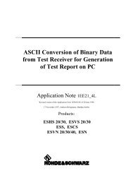
R&S ® <strong>FSV</strong>-<strong>K82</strong>/-<strong>K83</strong>Instrument Functions of the CDMA2000 AnalysisMeasurements and Result DisplaysRemote controlIn remote control, this display configuration is selected usingCALC:FEED 'XPOW:CDP'; see CALCulate:FEED on page 178.To query these results, use the command CALC:MARK:FUNC:CDP:RES? CDP orCALC:MARK:FUNC:CDP:RES? CDPR; see CALCulate:MARKer:FUNCtion:CDPower[:BTS]:RESult? on page 180.6.1.3.2 Channel TableThis result display shows all channels of the signal. The sorting of the channels is accordingto channel type, i.e. special channels like F-PICH, F-SYNC etc. first, then data channels(CHAN) and last inactive channels (always shown as '---'). Within a group, channelsare sorted according to the spreading factor and then according to code number, also inascending order. Within the code number, first active, then inactive channels are listed.The selected channel is marked in red. Active and inactive data channels are defined viathe "Inactive Channel Threshold" on page 64.The Channel Table result display may contain up to 128 entries, corresponding to thehighest base spreading factor of 128.The measurement evaluates the total signal over a single PCG.Fig. 6-3: Channel Table result displayFor the Code Domain Power measurement, the following parameters are determined forthe channels:ParameterChannel TypeWalsh Chan.SFSymb Rate/kspsRCStateDescriptionShows the channel type ('---' for inactive channels)Channel number including the spreading factor (in the form .).Symbol rate with which the channel is transmitted (9.6 ksps to 307.2 ksps).Radio configuration.Status display. Unassigned codes are identified as inactive channels.Operating Manual 1173.0750.02 ─ 0741
R&S ® <strong>FSV</strong>-<strong>K82</strong>/-<strong>K83</strong>Instrument Functions of the CDMA2000 AnalysisMeasurements and Result DisplaysParameterPwr dBm/Pwr dBT Offs/ns and PhOffs/mradDescriptionSpecification of the absolute (dBm) and relative (dB) power of the channel. Relativepowers are either referred to the pilot channel or the total power of the signal.Timing/phase offset between this channel and the pilot channel (enabled via the "Demod Settings (BTS mode)" on page 68 dialog box.If enabled, the maximum value of the timing/phase offset is displayed together with theassociated channel in the last two lines. Since the timing/phase offset values of eachactive channel can be either negative or positive, the absolute values are comparedand the maximum is displayed with the original sign.Remote controlIn remote control, this display configuration is selected usingCALC:FEED 'XTIM:CDP:ERR:CTABle'; see CALCulate:FEED on page 178.6.1.3.3 Power vs PCGIn this result display, the power of the selected channel is averaged for each measuredPCG and referred to the pilot power of the PCG. Therefore the unit of the y-axis is dB(relative to the Pilot Channel). The result display consists of the number of the PCGs inthe measurement and their respective power value.MS mode: the power is calculated only for the selected branch (I or Q).For signals with enabled power control, use the default reference power setting. Fordetails refer to "Power Reference" on page 74.The measurement evaluates one code channel over the entire period of observation. Theselected PCG is displayed red.You can set the number of PCGs by means of the "Capture Length" on page 61 field.Fig. 6-4: Power vs PCG result displayFor measurements in which Antenna Diversity is inactive (OFF) or set to 'Antenna 1', theF-PICH channel is used as reference, while the F-TDPICH channel is used for measurementsin which Antenna Diversity is set to 'Antenna 2'.Operating Manual 1173.0750.02 ─ 0742
R&S ® <strong>FSV</strong>-<strong>K82</strong>/-<strong>K83</strong>Instrument Functions of the CDMA2000 AnalysisMeasurements and Result DisplaysTo correctly detect the start of a power control group, the external trigger must be usedfor power-regulated signals.Remote controlIn remote control, this display configuration is selected usingCALC:FEED 'XTIM:CDP:PVSLot'; see CALCulate:FEED on page 178.6.1.3.4 Result SummaryThe Result Summary shows the results of various code domain measurements in a table.The table is divided as follows:●●●Global resultsPCG resultsChannel resultsFig. 6-5: Result Summary result displayRemote controlIn remote control, this display configuration is selected usingCALC:FEED 'XTIM:CDP:ERR:SUMMary'; see CALCulate:FEED on page 178.To query these results, use the command CALC:MARK:FUNC:CDP:RES? ; see CALCulate:MARKer:FUNCtion:CDPower[:BTS]:RESult? on page 180.Global ResultsUnder Global Results, the measurement results that concern the total signal (that is, allchannels) for the entire period of observation (that is, all PCGs) are displayed:●Carrier Frequency ErrorShows the frequency error referred to the center frequency of the R&S <strong>FSV</strong>. Theabsolute frequency error is the sum of the frequency error of the R&S <strong>FSV</strong> and thatof the device under test. Frequency differences between the transmitter and receiverof more than 1.0 kHz impair synchronization of the Code Domain Power measurement.If at all possible, the transmitter and the receiver should be synchronized. ForOperating Manual 1173.0750.02 ─ 0743
R&S ® <strong>FSV</strong>-<strong>K82</strong>/-<strong>K83</strong>Instrument Functions of the CDMA2000 AnalysisMeasurements and Result Displays●●●further information on correcting the frequency error refer to chapter 4.4, "Measuringthe Relative Code Domain Power and Frequency Error", on page 17 .The frequency error is available in the units both Hz and ppm referred to the carrierfrequency.Chip Rate ErrorShows the chip rate error (1.2288 Mcps) in ppm. A large chip rate error results insymbol errors and, therefore, in possible synchronization errors for Code DomainPower measurements. This measurement result is also valid if the R&S <strong>FSV</strong> couldnot synchronize to the CDMA2000 signal.Trigger to FrameReflects the time offset from the beginning of the recorded signal section to the startof the first PCG. In case of triggered data recording, this corresponds to the timingoffset:frame trigger (+ trigger offset) – start of first PCGIf it was not possible to synchronize the R&S <strong>FSV</strong> to the CDMA2000 signal, thismeasurement result is meaningless. For the Free Run trigger mode, dashes are displayed.Active ChannelsSpecifies the number of active channels found in the signal. Detected data channelsas well as special channels are regarded as active. With transmit diversity, the resultapplies to the selected "Antenna Diversity" on page 70. No value is displayed inboth the Min and Max columns.PCG ResultsUnder PCG, the measurement results that concern the total signal (that is, all channels)for the selected PCG are displayed:●●●●●Total PowerShows the total power of the signal.Pilot PowerShows the power of the pilot channel. If antenna 2 is selected, the power of the F-TDPICH is displayed, in all other cases that of the F-PICH. For details on antennaselection refer to "Antenna Diversity" on page 70.RHOShows the quality parameter RHO. According to the CDMA2000 standard, RHO isthe normalized, correlated power between the measured and the ideally generatedreference signal. When RHO is measured, the CDMA2000 standard requires thatonly the pilot channel be supplied.Composite EVMThe composite EVM is the difference between the test signal and the ideal referencesignal. For further details refer to the chapter 6.1.3.6, "Composite EVM (RMS)",on page 46 result display.IQ Imbalance/OffsetShows the IQ imbalance and the DC offset of the signal in %.Operating Manual 1173.0750.02 ─ 0744
R&S ® <strong>FSV</strong>-<strong>K82</strong>/-<strong>K83</strong>Instrument Functions of the CDMA2000 AnalysisMeasurements and Result DisplaysChannel resultsUnder Channel, the measurement results of the selected channel and the selected PCGare displayed:●●●●●●●Power RelativeShows the channel power of the selected channel and PCG. The result depends onthe selected Code Power, the Power Reference and absolute channel power.Power AbsoluteShows the absolute channel power of the selected channel and PCGTiming OffsetShows the timing offset between the selected channel and the pilot channel.Phase OffsetShows the phase offset between the selected channel and the pilot channel.Symbol EVMShows the peak or mean value of the EVM measurement result. For further detailsrefer to the chapter 6.1.3.9, "EVM vs Symbol", on page 49 result display.ModulationBTS mode only:Displays the modulation type of the channel and PCG: BPSK, QPSK, 8PSK, or16QAM.MappingIndicates the selected branch (I or Q)6.1.3.5 Code Domain Error PowerThis result display shows the difference in power of the test signal and an ideally generatedreference signal and plots in a diagram. The unit is dB. The x-axis represents thechannel (code) number, which corresponds to the base spreading factor. The y-axis is alogarithmic level axis that shows the error power of each channel. Since it is an errorpower, active and inactive channels can be rated jointly at a glance.The measurement evaluates the total signal over a single PCG. It supports both Hadamardand BitReverse code sorting order.MS mode: the error power is calculated only for the selected branch (I or Q).Fig. 6-6: Code Domain Error Power result display in Hadamard code sorting orderOperating Manual 1173.0750.02 ─ 0745
R&S ® <strong>FSV</strong>-<strong>K82</strong>/-<strong>K83</strong>Instrument Functions of the CDMA2000 AnalysisMeasurements and Result DisplaysFig. 6-7: Code Domain Error Power result display in BitReverse code sorting orderActive and inactive data channels are defined via the "Inactive Channel Threshold"on page 64. The power values of the active and inactive channels are shown in differentcolors. In addition, codes with alias power can occur. These codes obtain power componentsoriginating either from a spreading factor higher than the base spreading factoror from the own and/or another antenna as a result of transmit diversity.The following colors are defined:●●●●●Red: selected channel (Channel (Code) Number)Yellow: active channelCyan: inactiveLight blue: alias power of higher spreading factorMagenta: alias power as a result of transmit diversityIf codes with alias power are displayed, set the highest base spreading factor availablein the "Base Spreading Factor" on page 68 field.It is not recommended to select more detailed result displays (such as "Channel Constell")for unassigned or inactive codes, since the results are not valid.Remote controlIn remote control, this display configuration is selected usingCALC:FEED 'XPOW:CDEP'; see CALCulate:FEED on page 178.To query these results, use the command CALC:MARK:FUNC:CDP:RES? ; see CALCulate:MARKer:FUNCtion:CDPower[:BTS]:RESult? on page 180.6.1.3.6 Composite EVM (RMS)This result display is for measuring the modulation accuracy. It determines the error vectormagnitude (EVM) over the total signal. The EVM is the root of the ratio of the meanerror power (root mean square) to the power of an ideally generated reference signal.Thus, the EVM is shown in %. The diagram consists of a composite EVM for each PCG.Operating Manual 1173.0750.02 ─ 0746
R&S ® <strong>FSV</strong>-<strong>K82</strong>/-<strong>K83</strong>Instrument Functions of the CDMA2000 AnalysisMeasurements and Result DisplaysThe measurement evaluates the total signal over the entire period of observation. Theselected PCG is displayed red. You can set the number of PCGs in the "CaptureLength" on page 61 field.Fig. 6-8: Composite EVM result displayOnly the channels detected as being active are used to generate the ideal referencesignal. If a channel is not detected as being active, e.g. on account of low power, thedifference between the test signal and the reference signal and therefore the compositeEVM is very large. Distortions also occur if unassigned codes are wrongly given the statusof "active channel". To obtain reliable measurement results, select an adequate channelthreshold via the "Inactive Channel Threshold" on page 64 field.Remote controlIn remote control, this display configuration is selected usingCALC:FEED 'XTIM:CDP:MACCuracy'; see CALCulate:FEED on page 178.To query these results, use the command CALC:MARK:FUNC:CDP:RES?MACCuracy; see CALCulate:MARKer:FUNCtion:CDPower[:BTS]:RESult? on page 180.6.1.3.7 Peak Code Domain ErrorThe Peak Code Domain Error is defined as the maximum value for the Code DomainError for all codes. That means that in this result display the Code Domain Error Poweris projected onto the code domain at a specific base spreading factor. In the diagram,each bar of the x-axis represents one PCG. The y-axis represents the error power.You can select the base spreading factor in the "Base Spreading Factor" on page 68field and the number of evaluated PCGs in the "Capture Length" on page 61 field.The measurement evaluates the total signal over the entire period of observation. Thecurrently selected PCG is displayed red.MS mode: the error is calculated only for the selected branch (I or Q).Operating Manual 1173.0750.02 ─ 0747
R&S ® <strong>FSV</strong>-<strong>K82</strong>/-<strong>K83</strong>Instrument Functions of the CDMA2000 AnalysisMeasurements and Result DisplaysFig. 6-9: Peak Code Domain Error result displayOnly the channels detected as being active are used to generate the ideal referencesignal. If a channel is not detected as being active, e.g. on account of low power, thedifference between the test signal and the reference signal is very large. The result displaytherefore shows a peak code domain error that is too high. Distortions also occur ifunassigned codes are wrongly given the status of "active channel". To obtain reliablemeasurement results, select an adequate channel threshold via the "Inactive ChannelThreshold" on page 64 field.Remote controlIn remote control, this display configuration is selected usingCALC:FEED 'XTIM:CDP:ERR:PCDomain'; see CALCulate:FEEDon page 178.To query these results, use the command CALC:MARK:FUNC:CDP:RES? PCDerror;see CALCulate:MARKer:FUNCtion:CDPower[:BTS]:RESult?on page 180.6.1.3.8 Channel ConstellationThis result display shows the channel constellation of the modulated signal at symbollevel.The measurement evaluates a single channel over a single PCG.You can select a specific channel and PCG with the Select softkey.Operating Manual 1173.0750.02 ─ 0748
R&S ® <strong>FSV</strong>-<strong>K82</strong>/-<strong>K83</strong>Instrument Functions of the CDMA2000 AnalysisMeasurements and Result DisplaysFig. 6-10: Channel Constellation result display for QPSK-modulated signalThe R&S <strong>FSV</strong>-<strong>K82</strong> supports BPSK, QPSK, 8PSK and 16QAM modulation schemes. Themodulation scheme itself depends on the channel type. Refer to chapter 6.4.1.1, "RelationshipBetween Channel and Modulation Type", on page 150 for further information.In case of BPSK the constellation points are located on the x-axis. For the QPSK and16QAM schemes the constellation points are located on neither axis.Remote controlIn remote control, this display configuration is selected usingCALC:FEED 'XTIM:CDP:SYMB:CONStellation'; see CALCulate:FEEDon page 178.To query these results, use the command CALC:MARK:FUNC:CDP:RES? ; see CALCulate:MARKer:FUNCtion:CDPower[:BTS]:RESult? on page 180.6.1.3.9 EVM vs SymbolThis result display shows the EVM on symbol level. The x-axis represents the symbolsand the y-axis shows the EVM in %.The measurement evaluates a single channel over a single PCG.You can select a specific channel and PCG with the "Select" on page 77 softkey.Fig. 6-11: EVM vs Symbol result displayOperating Manual 1173.0750.02 ─ 0749
R&S ® <strong>FSV</strong>-<strong>K82</strong>/-<strong>K83</strong>Instrument Functions of the CDMA2000 AnalysisMeasurements and Result DisplaysThe number of symbols is in the range from 6 to 384 and can be calculated like this:Number of symbols = Number of chips in one PCG/ChannelSF/K, with"Number of chips in one PCG = 1536""Channel SF = 4, 8, 16, 32, 64 or 128""K = 1 for Antenna Diversity = OFF""K = 2 for Antenna Diversity = OFF"This calculation thus takes into account the results of a channel for a power control group.Inactive channels can be measured, but the result is meaningless since these channelsdo not contain data.Remote controlIn remote control, this display configuration is selected usingCALC:FEED 'XTIM:CDP:SYMB:EVM'; see CALCulate:FEED on page 178.To query these results, use the command CALC:MARK:FUNC:CDP:RES? ; see CALCulate:MARKer:FUNCtion:CDPower[:BTS]:RESult? on page 180.6.1.3.10 Composite ConstellationThis result display shows the constellation of the modulated signal at chip level. For eachof the 1536 chips, a constellation point is displayed in the diagram.The measurement evaluates the total signal over a single PCG.You can select a specific PCG with the "Select" on page 77 softkey.Fig. 6-12: Composite Constellation result displayRemote controlIn remote control, this display configuration is selected usingCALC:FEED 'XTIM:CDP:COMP:CONStellation'; see CALCulate:FEEDon page 178.Operating Manual 1173.0750.02 ─ 0750
R&S ® <strong>FSV</strong>-<strong>K82</strong>/-<strong>K83</strong>Instrument Functions of the CDMA2000 AnalysisMeasurements and Result DisplaysTo query these results, use the command CALC:MARK:FUNC:CDP:RES? ; see CALCulate:MARKer:FUNCtion:CDPower[:BTS]:RESult? on page 180.6.1.3.11 Power vs SymbolThis result display calculates the absolute power in dBm for every symbol number.The measurement evaluates a single channel over a single PCG.You can select a specific channel and PCG with the "Select" on page 77 softkey.Fig. 6-13: Power vs Symbol result displayRemote controlIn remote control, this display configuration is selected usingCALC:FEED 'XTIM:CDP:PVSYmbol'; see CALCulate:FEED on page 178.To query these results, use the command CALC:MARK:FUNC:CDP:RES? ; see CALCulate:MARKer:FUNCtion:CDPower[:BTS]:RESult? on page 180.6.1.3.12 Channel BitstreamThe result display provides information on the demodulated bits. All bits that are part ofinactive channels are marked as being invalid by means of dashes. For 16QAM modulation'----' is displayed, for 8PSK modulation '---', for QPSK '--' and for BPSK '-'.The measurement evaluates a single channel over a single PCG.You can select a specific channel and PCG with the Select softkey.Operating Manual 1173.0750.02 ─ 0751
R&S ® <strong>FSV</strong>-<strong>K82</strong>/-<strong>K83</strong>Instrument Functions of the CDMA2000 AnalysisMeasurements and Result DisplaysFig. 6-14: Bitstream result displaySelect a specific symbol using the MKR key. If you enter a number, the marker jumps tothe selected symbol. If there are more symbols than the screen is capable of displaying,use the marker to scroll inside the list.Depending on the spreading factor (symbol rate) of the channel, a power control groupmay contain a minimum of 12 and a maximum of 384 symbols. In case of an activetransmit diversity (Antenna Diversity) the values reduce to the half. Depending on themodulation type, a symbol consists of the following bits:●●●●BPSK: 1 bit (only the I-component is assigned)QPSK: 2 bits (I-component followed by the Q-component)8PSK: 3 bits16QAM: 4 bitsIn accordance with the radio configuration and the channel type, there are BPSK andQPSK modulated channels in the CDMA2000 system. For details refer to chapter 6.4.1.1,"Relationship Between Channel and Modulation Type", on page 150.In MS mode, only BPSK modulated channels are used, thus only the I-component isassigned.Operating Manual 1173.0750.02 ─ 0752
R&S ® <strong>FSV</strong>-<strong>K82</strong>/-<strong>K83</strong>Instrument Functions of the CDMA2000 AnalysisMeasurements and Result Displays6.1.4 RF Measurement Results6.1.4.1 Signal Channel PowerThe Signal Channel Power measurement analyses the RF signal power of a single channelwith 1.2288 MHz bandwidth over a single trace. The displayed results are based onthe root mean square. The configuration is according to the CDMA2000 requirements.Beneath the measurement screen the bandwidth and the associated channel power aredisplayed. The other screen elements match that of the screen of the Spectrum Analyzermode. The default settings are in accordance with the 3GPP2 specifications.SettingFrequency SpanACP StandardDefault Value2 MHz1xEV-DO0 MC1Number of adjacent channels 0Adjacent Channel PowerOnFor details on the softkeys of the Signal Channel Power measurement refer to the Power softkey in the "Measurement" menu.6.1.4.2 Adjacent Channel PowerThe Adjacent Channel Power measurement analyses the power of the TX channel andthe power of adjacent and alternate channels on the left and right side of the TX channel.The number of TX channels and adjacent channels can be modified as well as the bandclass. Beneath the measurement screens the bandwidth and power of the TX channeland the bandwidth, spacing and power of the adjacent and alternate channels are displayed.The default settings are in accordance with the 3GPP2 specifications.SettingAdjacent Channel PowerACP StandardDefault valueOn1xEV-DO0 MC1Number of adjacent channels 2For details on the softkeys of the Adjacent Channel Power measurement refer to the ChPower ACLR softkey in the "Measurement" menu.6.1.4.3 Spectrum Emission MaskThe Spectrum Emission Mask measurement shows the quality of the measured signalby comparing the power values in the frequency range near the carrier against a spectralmask that is defined by the 3GPP2 specifications. The limits depend on the selectedOperating Manual 1173.0750.02 ─ 0753
R&S ® <strong>FSV</strong>-<strong>K82</strong>/-<strong>K83</strong>Instrument Functions of the CDMA2000 AnalysisMeasurements and Result Displaysbandclass. In this way, the performance of the DUT can be tested and the emissions andtheir distance to the limit be identified.Note that the 3GPP2 standard does not distinguish between spurious and spectral emissions.Beneath the measurement screen a table showing the peak list. In the peak list the valuesfor the worst spectral emissions are displayed including their frequency and power.The default settings of the Spectrum Emission Mask measurement are listed in the tablebelow.SettingFrequency SpanSweep TimeDetectorDefault value8 MHz100 msRMSFor details on the softkeys of the Spectrum Emission Mask measurement refer to the Spectrum Emission Mask softkey in the "Measurement" menu.6.1.4.4 Occupied BandwidthThe Occupied Bandwidth measurement determines the bandwidth in which the signalpower can be found. By default the bandwidth is displayed in which 99 % of the signal isfound. The percentage of the signal power included in the measurement can be modified.In the top right corner of the screen, the bandwidth and frequency markers are displayed.The default settings of the Occupied Bandwidth measurement are listed in the tablebelow.SettingOccupied BandwidthFrequency SpanSweep TimeRBWVBWDetectorDefault valueON4.2 MHz100 ms30 kHz300 kHzRMSFor details on the softkeys of the Occupied Bandwidth measurement see OccupiedBandwidth in the "Measurement" menu.6.1.4.5 Complementary Cumulative Distribution Function (CCDF)The CCDF measurement displays the CCDF and the Crest factor. The CCDF showsdistribution of the signal amplitudes. For the measurement, a signal section of settablelength is recorded continuously in a zero span. The measurement is useful to determineOperating Manual 1173.0750.02 ─ 0754
R&S ® <strong>FSV</strong>-<strong>K82</strong>/-<strong>K83</strong>Instrument Functions of the CDMA2000 AnalysisMenu and Softkey Description for CDA Measurementserrors of linear amplifiers. The Crest factor is defined as the ratio of the peak power andthe mean power. Beneath the measurement screen a table containing the number ofincluded samples, mean and peak power and the Crest factor is displayed.The default settings of the CCDF measurement are listed in the table below.SettingCCDFRBWDetectorDefault valueON10 MHzSampleFor details on the softkeys of the CCDF measurement see CCDF in the "Measurement"menu.6.2 Menu and Softkey Description for CDA MeasurementsThis chapter describes the menus and softkeys available in CDMA2000 BTS Analysismode for CDA measurements. For RF measurements, the softkeys are described in chapter 6.3, "Softkeys and Menus for RF Measurements (<strong>K82</strong>)", on page 95.The "Lines" menu is not available in the CDMA2000 BTS Analysis mode.The "Span" menu is not available for code domain measurements and signal powermeasurements.The "Bandwidth" menu is not available for code domain measurements measurements.All menus not described here are the same as for the base unit, see the description there.Importing and Exporting I/Q DataAs of firmware version 1.60, I/Q data can be imported from a file for processing inR&S <strong>FSV</strong>-<strong>K82</strong>/-<strong>K83</strong>, and captured I/Q data can be stored to a file ("IQ Import"/"IQExport" softkeys in the "Save/Rcl" menu). For details see the base unit description.To display help to a softkey, press the HELP key and then the softkey for which you wantto display help. To close the help window, press the ESC key. For further informationrefer to chapter 1.3, "How to Use the Help System", on page 8.6.2.1 Softkeys of the Code Domain Analyzer Menu..............................................................566.2.2 Softkeys of the Frequency Menu..................................................................................786.2.3 Softkeys of the Amplitude Menu...................................................................................796.2.4 Softkeys of the Sweep Menu........................................................................................826.2.5 Softkeys of the Trigger Menu for CDA measurements.................................................836.2.6 Softkeys of the Trace Menu for CDA Measurements....................................................846.2.7 Softkeys of the Marker Menu for CDA Measurements..................................................86Operating Manual 1173.0750.02 ─ 0755
R&S ® <strong>FSV</strong>-<strong>K82</strong>/-<strong>K83</strong>Instrument Functions of the CDMA2000 AnalysisMenu and Softkey Description for CDA Measurements6.2.8 Softkeys of the Marker To Menu...................................................................................876.2.9 Softkeys of the Auto Set Menu......................................................................................896.2.10 Softkeys of the Input/Output Menu for CDA Measurements.........................................916.2.1 Softkeys of the Code Domain Analyzer MenuThe following chapter describes all softkeys available in the "Code Domain Analyzer"menu of the CDMA2000 Analysis options.Settings Overview.........................................................................................................57Frontend Settings..........................................................................................................59└ Center.............................................................................................................60└ Frequency Offset............................................................................................60└ Ref Level.........................................................................................................60└ Ref Level Offset..............................................................................................60└ Preamp On/Off................................................................................................61└ Adjust Ref Lvl..................................................................................................61IQ Capture Settings.......................................................................................................61└ Invert Q...........................................................................................................61└ Capture Length...............................................................................................61└ Set Count........................................................................................................62└ Set to Analyze.................................................................................................62└ Trigger Source Free Run................................................................................62└ Trigger Source External..................................................................................62└ Trigger Polarity................................................................................................62└ Trigger Offset..................................................................................................63Channel Table Settings.................................................................................................63└ Channel Search Mode....................................................................................64└ Inactive Channel Threshold............................................................................64└ Channel Tables...............................................................................................65└ New / Copy / Edit............................................................................................65└ Add Channel.........................................................................................67└ Delete Channel.....................................................................................67└ Meas.....................................................................................................67└ Sort.......................................................................................................67└ Save......................................................................................................67└ Cancel...................................................................................................67└ Reload..................................................................................................68└ Delete..............................................................................................................68└ Restore Default Tables...................................................................................68Demod Settings (BTS mode)........................................................................................68└ Base Spreading Factor...................................................................................68└ PN Offset........................................................................................................69└ Multi Carrier....................................................................................................69└ Enhanced Algorithm........................................................................................69└ Multi Carrier Filter...........................................................................................69└ Filter Type.......................................................................................................69└ Roll-Off Factor.................................................................................................70Operating Manual 1173.0750.02 ─ 0756
R&S ® <strong>FSV</strong>-<strong>K82</strong>/-<strong>K83</strong>Instrument Functions of the CDMA2000 AnalysisMenu and Softkey Description for CDA Measurements└ Cut Off Frequency...........................................................................................70└ Antenna Diversity............................................................................................70Base SF/Long Code (MS mode)...................................................................................71└ Base Spreading Factor...................................................................................71└ Long Code Mask.............................................................................................72└ Long Code Offset............................................................................................72└ Long Code Gen Mode.....................................................................................72Result Settings..............................................................................................................72└ Power Control Group......................................................................................73└ Channel (Code) Number.................................................................................73└ Code Order.....................................................................................................74└ Code Power....................................................................................................74└ Pilot Power (MS mode only)...........................................................................74└ Power Reference............................................................................................74└ Time/Phase Estimation...................................................................................75└ Normalize........................................................................................................75└ Code Domain Overview (MS mode only)........................................................75Display Config...............................................................................................................75Select............................................................................................................................77Settings OverviewThis softkey opens the "Settings Overview" dialog box that visualizes the data flow of theCode Domain Analyzer and summarizes all of the current settings. In addition, you canchange the current settings via this dialog box.To reset all values to their default state, press the "Set to Default" button.Operating Manual 1173.0750.02 ─ 0757
R&S ® <strong>FSV</strong>-<strong>K82</strong>/-<strong>K83</strong>Instrument Functions of the CDMA2000 AnalysisMenu and Softkey Description for CDA MeasurementsFig. 6-15: Settings overview in CDMA2000 BTS mode (<strong>K82</strong>)Operating Manual 1173.0750.02 ─ 0758
R&S ® <strong>FSV</strong>-<strong>K82</strong>/-<strong>K83</strong>Instrument Functions of the CDMA2000 AnalysisMenu and Softkey Description for CDA MeasurementsFig. 6-16: Settings overview in CDMA2000 MS mode (<strong>K83</strong>)To change the settings, either use the rotary knob or the cursor keys to change the focusto any other block or press one of the following buttons:● "Frontend Settings" on page 59● "IQ Capture Settings" on page 61● "Demod Settings (BTS mode)" on page 68● "Base SF/Long Code (MS mode)" on page 71● "Channel Table Settings" on page 63● "Result Settings" on page 72● "Display Config" on page 75When using the rotary knob or the cursor keys, press the ENTER key to open the correspondingdialog box. The "Settings Overview" dialog box always remains open whilesettings are modified.Frontend SettingsThis softkey opens the "Frontend Settings" dialog box to modify the following parameters:Operating Manual 1173.0750.02 ─ 0759
R&S ® <strong>FSV</strong>-<strong>K82</strong>/-<strong>K83</strong>Instrument Functions of the CDMA2000 AnalysisMenu and Softkey Description for CDA MeasurementsCenter ← Frontend SettingsOpens an edit dialog box to enter the center frequency. The allowed range of values forthe center frequency depends on the frequency span.span > 0: span min /2 ≤ f center ≤ f max – span min /2span = 0: 0 Hz ≤ f center ≤ f maxf max and span min are specified in the data sheet.Remote command:[SENSe:]FREQuency:CENTer on page 259Frequency Offset ← Frontend SettingsOpens an edit dialog box to enter a frequency offset that shifts the displayed frequencyrange by the specified offset.The softkey indicates the current frequency offset. The allowed values range from-100 GHz to 100 GHz. The default setting is 0 Hz.Remote command:[SENSe:]FREQuency:OFFSet on page 260Ref Level ← Frontend SettingsOpens an edit dialog box to enter the reference level in the current unit (dBm, dBµV, etc).The reference level is the maximum value the AD converter can handle without distortionof the measured value. Signal levels above this value will not be measured correctly,which is indicated by the "IFOVL" status display.Remote command:DISPlay[:WINDow]:TRACe:Y[:SCALe]:RLEVel on page 230Ref Level Offset ← Frontend SettingsOpens an edit dialog box to enter the arithmetic level offset. This offset is added to themeasured level irrespective of the selected unit. The scaling of the y-axis is changedaccordingly. The setting range is ±200 dB in 0.1 dB steps.Remote command:DISPlay[:WINDow]:TRACe:Y[:SCALe]:RLEVel:OFFSet on page 231Operating Manual 1173.0750.02 ─ 0760
R&S ® <strong>FSV</strong>-<strong>K82</strong>/-<strong>K83</strong>Instrument Functions of the CDMA2000 AnalysisMenu and Softkey Description for CDA MeasurementsPreamp On/Off ← Frontend SettingsSwitches the preamplifier on and off.If option R&S <strong>FSV</strong>-B22 is installed, the preamplifier is only active below 7 GHz.If option R&S <strong>FSV</strong>-B24 is installed, the preamplifier is active for all frequencies.This function is not available for input from the R&S Digital I/Q Interface (option R&S <strong>FSV</strong>-B17).Remote command:INPut:GAIN:STATe on page 291Adjust Ref Lvl ← Frontend SettingsDefines the optimal reference level for the current measurement automatically.Remote command:[SENSe:]ADJust:LEVel on page 244IQ Capture SettingsThis softkey opens the "IQ Capture Settings" dialog box.Invert Q ← IQ Capture SettingsInverts the sign of the signal's Q-component. The default setting is OFF.Remote command:[SENSe:]CDPower:QINVert on page 240Capture Length ← IQ Capture SettingsSets the number of PCGs you want to analyze. The input value is always in multiples ofthe PCGs. The maximum capture length is 64.The "Capture Length" field is available if" Set Count" equals 1.Operating Manual 1173.0750.02 ─ 0761
R&S ® <strong>FSV</strong>-<strong>K82</strong>/-<strong>K83</strong>Instrument Functions of the CDMA2000 AnalysisMenu and Softkey Description for CDA MeasurementsThe default value is 3.Remote command:[SENSe:]CDPower:IQLength on page 236Set Count ← IQ Capture SettingsDefines the number of consecutive sets to be stored in the instrument's IQ memory. Oneset consists of 64 PCGs. The R&S <strong>FSV</strong> can capture up to 31360 PCGs (about 26 seconds)in a single sweep, i.e. the possible value range is from 1 to 490 sets.The default setting is 1. In that case you can still define the number of PCGs (see "CaptureLength" on page 61). In case you want to capture more than one set, the capture lengthis always 64. The R&S <strong>FSV</strong> automatically sets the capture length to 64 and the "CaptureLength" on page 61 field is not available for modification.Remote command:[SENSe:]CDPower:SET:COUNt on page 240Set to Analyze ← IQ Capture SettingsSelects a specific set for further analysis. The value range depends on the "Set Count"and is between 0 and "Set Count" – 1.Remote command:[SENSe:]CDPower:SET on page 240Trigger Source Free Run ← IQ Capture SettingsThe start of a sweep is not triggered. Once a measurement is completed, another isstarted immediately.For further details refer to the "Trigger Source" field in the "IQ Capture Settings" dialogbox.This softkey is available for code domain measurements.Remote command:TRIG:SOUR IMM, see TRIGger[:SEQuence]:SOURce on page 294Trigger Source External ← IQ Capture SettingsDefines triggering via a TTL signal at the "EXT TRIG/GATE IN" input connector on therear panel.An edit dialog box is displayed to define the external trigger level.For further details refer to the "Trigger Source" field in the "IQ Capture Settings" dialogbox.This softkey is available for code domain measurements.Remote command:TRIG:SOUR EXT, see TRIGger[:SEQuence]:SOURce on page 294Trigger Polarity ← IQ Capture SettingsSets the polarity of the trigger source.The sweep starts after a positive or negative edge of the trigger signal. The default settingis "Pos". The setting applies to all modes with the exception of the "Free Run" and"Time" mode.Operating Manual 1173.0750.02 ─ 0762
R&S ® <strong>FSV</strong>-<strong>K82</strong>/-<strong>K83</strong>Instrument Functions of the CDMA2000 AnalysisMenu and Softkey Description for CDA MeasurementsThis softkey is available for code domain measurements."Pos""Neg"Level triggering: the sweep is stopped by the logic "0" signal and restartedby the logical "1" signal after the gate delay time has elapsed.Edge triggering: the sweep is continued on a "0" to "1" transition for thegate length duration after the gate delay time has elapsed.Remote command:TRIGger[:SEQuence]:SLOPe on page 294[SENSe:]SWEep:EGATe:POLarity on page 272Trigger Offset ← IQ Capture SettingsOpens an edit dialog box to enter the time offset between the trigger signal and the startof the sweep.offset > 0:offset < 0:Start of the sweep is delayedSweep starts earlier (pre-trigger)Only possible for span = 0 (e.g. I/Q Analyzer mode) and gated triggerswitched offMaximum allowed range limited by the sweep time:pretrigger max = sweep timeWhen using the R&S Digital I/Q Interface (R&S <strong>FSV</strong>-B17) with I/Q Analyzermode, the maximum range is limited by the number of pretrigger samples.See the R&S Digital I/Q Interface(R&S <strong>FSV</strong>-B17) description in the baseunit.In the "External" or "IF Power" trigger mode, a common input signal is used for both triggerand gate. Therefore, changes to the gate delay will affect the trigger delay (trigger offset)as well.Remote command:TRIGger[:SEQuence]:HOLDoff[:TIME] on page 293Channel Table SettingsOpens the "Channel Table Settings" dialog box and the corresponding submenu.Operating Manual 1173.0750.02 ─ 0763
R&S ® <strong>FSV</strong>-<strong>K82</strong>/-<strong>K83</strong>Instrument Functions of the CDMA2000 AnalysisMenu and Softkey Description for CDA MeasurementsPredefined channel tables allow you to customize measurements very quickly and easily.They are included in the option by default and contain settings according to specificstandards. For details on the predefined channel tables refer to chapter 6.4.1, "PredefinedChannel Tables", on page 147. In addition, new channel tables can be created and savedto be used in measurements.Channel Search Mode ← Channel Table SettingsDefines the kind of channel table used for the measurement."Auto""Predef"The Auto Search mode scans the whole code domain, including allpermissible symbol rates and channel numbers, for active channels.The automatic search provides an overview of the channels containedin the signal. If channels are not detected as being active, change thethreshold (see "Inactive Channel Threshold" on page 64) or select thePredefined channel search type.Performs the code domain measurement on the basis of the active predefinedchannel table. All channels of a channel table are assumed tobe active. For further details also refer to the "Channel Tables"on page 65 field and the chapter 6.4.1, "Predefined ChannelTables", on page 147 .Remote command:CONFigure:CDPower[:BTS]:CTABle[:STATe] on page 219CONFigure:CDPower[:BTS]:CTABle:SELect on page 223Inactive Channel Threshold ← Channel Table SettingsDefines the minimum power which a single channel must have compared to the totalsignal in order to be recognized as an active channel. Channels below the specifiedthreshold are regarded as "inactive". The parameter is available in the Auto Search modeof the Channel Table Settings dialog box.Operating Manual 1173.0750.02 ─ 0764
R&S ® <strong>FSV</strong>-<strong>K82</strong>/-<strong>K83</strong>Instrument Functions of the CDMA2000 AnalysisMenu and Softkey Description for CDA MeasurementsThe default value is -60 dB. With this value all channels with signals such as theCDMA2000 test models are located by the Code Domain Power analysis. Decrease theInactive Channel Threshold value, if not all channels contained in the signal are detected.Remote command:[SENSe:]CDPower:ICThreshold on page 235Channel Tables ← Channel Table SettingsIn this field a list of the available channel tables is shown. The selected channel table isthe basis for future measurements (until you choose another or activate "Auto Search").An active channel table must describe the supplied signal completely, also in regard tothe transmit diversity (see "Antenna Diversity" on page 70).Using the softkeys, customized channel tables can be defined or existing channel tablescan be modified.The following channel tables are available by default:"RECENT""BPC_RC4,MPC_RC1,MPC_RC4,TDC_RC4""EACHOP,RCCCHOP,RTCHOP3,RTCHOP5"Contains the last configuration used before switching from "AutoSearch" to "Predefined"Channel tables for BTS mode (<strong>K82</strong>); configured according to a specificstandardChannel tables for MS mode (<strong>K83</strong>); configured according to a specificstandardRemote command:CONFigure:CDPower[:BTS]:CTABle:CATalog? on page 219New / Copy / Edit ← Channel Table SettingsAll three softkeys open a dialog box with the same layout and the same correspondingsubmenu.The "New" softkey opens the "New Channel Table" dialog box. In this dialog you canbuild a new channel table. All fields are empty.The "Copy" softkey copies all elements of the selected channel table and opens the "CopyChannel Table" dialog box. The name of the new channel table is set to "Copy of ".The "Edit" softkey opens the "Edit Channel Table" dialog box and the correspondingmenu. In this dialog box you can edit an existing channel table.Note that changes are never saved automatically. Save your channel tables before endingthe application (Save softkey). For more information see chapter 6.4.2, "Working withChannel Tables", on page 151.The dialog box contains the following items. You can modify the white fields as you like.The grey fields can not be modified; these are automatically calculated by the R&S <strong>FSV</strong>:Operating Manual 1173.0750.02 ─ 0765
R&S ® <strong>FSV</strong>-<strong>K82</strong>/-<strong>K83</strong>Instrument Functions of the CDMA2000 AnalysisMenu and Softkey Description for CDA MeasurementsItemNameDescriptionChannel TypeWalsh Ch.SFSymbol Rate/kspsRC(BTS mode only)Mapping (MS mode only)Power/dBStateDomainConflictDescriptionEnter the name of the selected channel table, which will be saved under.xml. The name is case sensitive and may not contain spaces. Itmust be a valid MS Windows file name. Note that the old channel table fileis not deleted.Enter further information about the channel table.Select one of the channel types from the dropdown menu.Enter the Channel Number (Ch) and Spreading Factor (SF). For somechannel types the possible values are limited or preset (e.g. F-PICH, F-TDPICH and F-PDCH).Display of the symbol rateThe Radio Configuration (RC) can be customized for two channel types. Forthe F-PDCH the you can set the configuration to either 10 (QPSK), 10(8PSK) and 10 (16QAM). For CHAN channels, you can set the radio configurationto 1-2 or 3-5.Specifies whether the channel is active on the I or Q branch.Contains the measured relative code domain power. The unit is dB. Thefields are filled with values after pressing the Meas softkey.Indicates whether a channel is active or inactive.A red bullet indicates a conflict of any sorts between two or more channels(e.g. two conflicting channel codes)Operating Manual 1173.0750.02 ─ 0766
R&S ® <strong>FSV</strong>-<strong>K82</strong>/-<strong>K83</strong>Instrument Functions of the CDMA2000 AnalysisMenu and Softkey Description for CDA MeasurementsAdd Channel ← New / Copy / Edit ← Channel Table SettingsInserts a new channel below the selected one. For a description of the parameters of thechannel refer to the "New / Copy / Edit" on page 65 softkey. The default values for a newchannel are:ChannelTypeCHANWalsh.SF 0.64Sym Rate/kspsRC(BTS mode only)Mapping (MS mode only)Power/dBStateDomainConflictautomatically calculated3-5Iautomatically calculatedOffautomatically calculatedThe R&S <strong>FSV</strong> automatically checks for conflicts between two active channels.Remote command:CONFigure:CDPower[:BTS]:CTABle:DATA on page 220Delete Channel ← New / Copy / Edit ← Channel Table SettingsDeletes the selected channel without further notice.Meas ← New / Copy / Edit ← Channel Table SettingsInitiates a measurement in "Auto Search" mode (see "Channel Search Mode"on page 64). The measurement results are applied to the active channel table. The activechannel table is overwritten without further notice.The softkey is only available if the "Auto Search" mode is enabled "in the Channel TableSettings" dialog box.Sort ← New / Copy / Edit ← Channel Table SettingsSorts the table according to the following criteria (in the specified order):●●●●Channel state (active channels first, then inactive channels)Channel type (special channels like F-PICH or F-SYNC first, then data channels)Spreading factor (in ascending order)Code number (in ascending order)Save ← New / Copy / Edit ← Channel Table SettingsSaves the table under its specified name in the xml-format. If you edit a channel tableand want to keep the original channel table, change the name of the edited channel tablebefore saving it.Cancel ← New / Copy / Edit ← Channel Table SettingsCloses the dialog box and returns to the "Channel Table Settings" dialog box. Changesapplied to the channel table are lost.Operating Manual 1173.0750.02 ─ 0767
R&S ® <strong>FSV</strong>-<strong>K82</strong>/-<strong>K83</strong>Instrument Functions of the CDMA2000 AnalysisMenu and Softkey Description for CDA MeasurementsReload ← New / Copy / Edit ← Channel Table SettingsReloads the original content of the copied channel table.This softkey is available for the "New Channel Table" dialog box and the "Edit ChannelTable" dialog box.Delete ← Channel Table SettingsDeletes the selected channel table. The currently active channel table cannot be deleted.Restore Default Tables ← Channel Table SettingsRestores the predefined channel tables (see chapter 6.4.1, "Predefined ChannelTables", on page 147 ) to their factory-set values. Existing channel tables with the samename as default channel tables are replaced by this action. In this way, you can undounintentional overwriting.Demod Settings (BTS mode)This softkey opens the "Demodulation Settings" dialog box.Base Spreading Factor ← Demod Settings (BTS mode)Sets the base spreading factor to either 64 or 128. If you set the base spreading factorto 64 for channels with a base spreading factor of 128 (code class 7), an alias power isdisplayed in the Code Domain Power and Code Domain Error Power diagrams.Remote command:[SENSe:]CDPower:SFACtor on page 241Operating Manual 1173.0750.02 ─ 0768
R&S ® <strong>FSV</strong>-<strong>K82</strong>/-<strong>K83</strong>Instrument Functions of the CDMA2000 AnalysisMenu and Softkey Description for CDA MeasurementsPN Offset ← Demod Settings (BTS mode)Specifies the Pseudo Noise (PN) offset of the base station. In a CDMA2000 system, thePN offset is used to distinguish the base stations.The PN offset determines the offset in the circulating PN sequence in multipls of 64 chipswith reference to the event second clock trigger.Although the parameter is always available, it has an effect only in External trigger mode.Remote command:[SENSe:]CDPower:PNOFfset on page 239Multi Carrier ← Demod Settings (BTS mode)Activates or deactivates the Multi Carrier mode. The mode improves the processing ofmulti carrier signals. It allows the measurement on one carrier out of a multi carrier signal.Remote command:CONFigure:CDPower[:BTS]:MCARrier [:STATe] on page 223Enhanced Algorithm ← Demod Settings (BTS mode)Activates or deactivates the enhanced algorithm that is used for signal detection on multicarriersignals. This algorithm slightly increases the calculation time.If both the Enhanced Algorithm and the "Multi Carrier Filter" on page 69 are deactivated,the multi carrier mode is automatically switched off.Remote command:CONFigure:CDPower[:BTS]:MCARrier:MALGo on page 225Multi Carrier Filter ← Demod Settings (BTS mode)Activates or deactivates the usage of a filter for signal detection on multi-carrier signals.If both the "Enhanced Algorithm" on page 69 and the Multi Carrier Filter are deactivated,the multi carrier mode is automatically switched off.Remote command:CONFigure:CDPower[:BTS]:MCARrier:FILTer [:STATe] on page 223Filter Type ← Demod Settings (BTS mode)Selects the filter type if "Multi Carrier Filter" on page 69 is activated.Two filter types are available for selection: a low-pass filter and a RRC filter.By default, the low-pass filter is active. The low-pass filter affects the quality of the measuredsignal compared to a measurement without a filter. The frequency response of thelow-pass filter is shown below.Operating Manual 1173.0750.02 ─ 0769
R&S ® <strong>FSV</strong>-<strong>K82</strong>/-<strong>K83</strong>Instrument Functions of the CDMA2000 AnalysisMenu and Softkey Description for CDA MeasurementsThe RRC filter comes with an integrated Hamming window. If selected, two more settingsbecome available for configuration: the "Roll-Off Factor" on page 70 and the "Cut OffFrequency" on page 70.Remote command:CONFigure:CDPower[:BTS]:MCARrier:FILTer:TYPE on page 224Roll-Off Factor ← Demod Settings (BTS mode)Defines the roll-off factor of the RRC filter. The roll-off factor defines the slope of the filtercurve and therefore the excess bandwidth of the filter. Possible values are between 0.01and 0.99 in 0.01 steps. The default value is 0.02.This parameter is available for the RRC filter.Remote command:CONFigure:CDPower[:BTS]:MCARrier:FILTer:TYPE on page 224CONFigure:CDPower[:BTS]:MCARrier:FILTer:ROFF on page 224Cut Off Frequency ← Demod Settings (BTS mode)Defines the cut-off frequency of the RRC filter. The cutoff frequency is the frequency atwhich the passband of the filter begins. Possible values are between 0.1 MHz and 2.4MHz in 1 Hz steps. The default value is 1.25 MHzThis parameter is available for the RRC filter.Remote command:CONFigure:CDPower[:BTS]:MCARrier:FILTer:TYPE on page 224CONFigure:CDPower[:BTS]:MCARrier:FILTer:COFRequency on page 224Antenna Diversity ← Demod Settings (BTS mode)Activates or deactivates the orthogonal transmit diversity (two-antenna system) anddefines the antenna for which the results are displayed.Operating Manual 1173.0750.02 ─ 0770
R&S ® <strong>FSV</strong>-<strong>K82</strong>/-<strong>K83</strong>Instrument Functions of the CDMA2000 AnalysisMenu and Softkey Description for CDA Measurements"Antenna 1""Antenna 2""Off"The signal of antenna 1 is fed in.The pilot channel (F-PICH) with channel number 0 and spreading factor64 (0.64) is required.If a channel table is used in the measurement (see Channel Table), itmust contain the pilot channel (F-PICH), but must not contain the transmitdiversity pilot channel (F-TDPICH).As reference for the code power (Power Reference), PICH is used.The signal of antenna 2 is fed in.The transmit diversity pilot channel (F-TDPICH) with channel number16 and spreading factor 128 (16.128) is required.If a channel table is used in the measurement (see Channel Table), itmust contain the transmit diversity pilot channel (F-TDPICH), but mustnot contain the pilot channel (F-PICH).As reference for the code power (Power Reference), F-TDPICH is used.The aggregate signal from both antennas is fed in.The pilot channels of both antennas are required.If a channel table is used in the measurement (see Channel Table), itmust contain both the transmit diversity pilot channel (F-TDPICH) andthe pilot channel (F-PICH).As reference for the code power (Power Reference), F-PICH is used.Remote command:[SENSe:]CDPower:ANTenna on page 235Base SF/Long Code (MS mode)This softkey opens the "Base SF/Long Code" dialog box. These settings are used toidentify the base stations during mobile measurements.Base Spreading Factor ← Base SF/Long Code (MS mode)Sets the base spreading factor. Possible values are 16, 32, 64.Operating Manual 1173.0750.02 ─ 0771
R&S ® <strong>FSV</strong>-<strong>K82</strong>/-<strong>K83</strong>Instrument Functions of the CDMA2000 AnalysisMenu and Softkey Description for CDA MeasurementsIf channels with a spreading factor of 64 are analyzed, use the base spreading factor 64.Otherwise alias power is displayed in the "CODE DOMAIN POWER" and "CODEDOMAIN ERROR POWER" diagram.Remote command:[SENSe:]CDPower:SFACtor on page 241Long Code Mask ← Base SF/Long Code (MS mode)Defines the long code mask of the mobile in hexadecimal form. The value range is from0 to 4FFFFFFFFFF.For the default mask value of 0 the long code offset (refer to the "LONG CODE OFF-SET" softkey) is not taken into consideration.Remote command:[SENSe:]CDPower:LCODe:MASK on page 236Long Code Offset ← Base SF/Long Code (MS mode)Defines the long code offset, including the PN offset, in chips in hexadecimal format witha 52-bit resolution. This value corresponds to the GPS timing since 6.1.1980 00:00:00UTC. This offset is applied at the next trigger pulse (which cannot occur until a setup timeof 300 ms has elapsed). The default value is 0.The setting is ignored if the "Long Code Mask" is set to 0.The chips offset is calculated as follows:tSinceStartGPS * 1.2288 MChips/swhere tSinceStartGPS is defined in secondsRemote command:[SENSe:]CDPower:LCODe:OFFSet on page 237Long Code Gen Mode ← Base SF/Long Code (MS mode)Selects the mode of the long code generation."Standard""ESG 101"The cdma2000 standard long code generator is used.The Agilent ESG option 101 long code is used; in this case, only signalsfrom that generator can be analysed.Remote command:[SENSe:]CDPower:LCODe:MODE on page 237Result SettingsThis softkey opens the "Result Settings" dialog box to modify the following parameters:Operating Manual 1173.0750.02 ─ 0772
R&S ® <strong>FSV</strong>-<strong>K82</strong>/-<strong>K83</strong>Instrument Functions of the CDMA2000 AnalysisMenu and Softkey Description for CDA MeasurementsPower Control Group ← Result SettingsIn some measurements it is possible to highlight the data of a specific PCG. Select thePCG on which to put the focus on in this field. The range of the value depends on the "Capture Length" on page 61 defined in the IQ Capture Settings dialog box. Thereforethe range is (0 to Capture Length-1).The defined value is valid for any measurement which takes PCGs into account (for furtherinformation see also the "Select" on page 77 softkey). The selected PCG is highlightedin red on the screen (as opposed to the others which are displayed in yellow).Remote command:[SENSe:]CDPower:SLOT on page 241Channel (Code) Number ← Result SettingsThe entry in this field corresponds to a specific code to be examined. The valid range isfrom 0 to BSF-1. The base spreading factor (BSF) is either 64 or 128 depending on thesetting of the "Base Spreading Factor" on page 68 field. It can not be edited via this field.The selected channel is marked red in the Channel Table. In the Code Domain Powerdisplay and the Code Domain Error Power display, all codes belonging to this channelare marked red.The defined value is valid for any measurement that takes a selected channel intoaccount. For further information see the "Select" on page 77 softkey.The rotary knob behavior depends on the result display and the graphic display:●in the Code Domain Power and Code Domain Error result displays, the rotary knobalways selects the adjacent channel. The position of the adjacent channel in the diagramdepends on the "Code Order" on page 74.Operating Manual 1173.0750.02 ─ 0773
R&S ® <strong>FSV</strong>-<strong>K82</strong>/-<strong>K83</strong>Instrument Functions of the CDMA2000 AnalysisMenu and Softkey Description for CDA Measurements●in the Channel Table result display, the rotary knob is used to scroll through the list.Remote command:[SENSe:]CDPower:CODE on page 235Code Order ← Result SettingsSets the sorting of the channels for the Code Domain Power and Code Domain Errorresult displays.Hadamard order:Bit-Reverse order:By default, the codes are sorted in Hadamard order, i.e. in ascending order.You can see the power of each code in this way; there is no distinctionbetween channels apparent. If there is a channel covering several codes,the display shows the individual power of each code.Example (for base spreading factor of 64):0.64, 1.64, 2.64, …, 63.64.Bundles the channels with concentrated codes, i.e. all codes of a channelare next to one another. In this way you can see the total power of a concentratedchannel.Example (for base spreading factor of 64):0.64, 32.64, 16.64, 48.64, 8.64, 40.64, …, 15.64, 47.64,31.64, 63.64For further details on the code order refer to the Hadamard and BitReverse Code Tablesin the Appendix on page.Remote command:[SENSe:]CDPower:ORDer on page 238Code Power ← Result SettingsSelects the y-axis scaling for the Code Domain Power result display.●●Absolute scaling shows the code power in dBm.Relative scaling shows the code power in dB.You can set the reference in the "Power Reference" on page 74 field.Remote command:CALCulate:FEED on page 178Pilot Power (MS mode only) ← Result SettingsDisplays the pilot power in absolute or relative values.Remote command:[SENSe:]CDPower:PPReference on page 239Power Reference ← Result SettingsDetermines the reference power for relative power measurements.Pilot ChannelTotal PowerBy default, the reference power is the power of the pilot channel. Which pilotchannel is used as the reference depends on the "Antenna Diversity"on page 70.The power is measured over one PCG. The reference power is the totalpower of the signal for the corresponding PCG.Operating Manual 1173.0750.02 ─ 0774
R&S ® <strong>FSV</strong>-<strong>K82</strong>/-<strong>K83</strong>Instrument Functions of the CDMA2000 AnalysisMenu and Softkey Description for CDA MeasurementsBy default, the power of the channels is referred to the power of the pilot channel (codenumber 0). The power of the pilot channel is identical over all PCGs. Therefore it can beused as a constant reference for the result display. In contrast, the total power can varyfrom PCG to PCG due to the possibility of a power level change in the different codechannels.In the Power vs PCG result display, with enabled power control and reference to the totalpower of the signal, the power control of the selected channel is not necessarily reflected.Example (theoretical):There is just one data channel in the signal and its power is controlled.The power is referred to the total power of the signal (which consists only of the contributionfrom this one data channel).In the Power vs. PCG diagram, a straight line is displayed instead of the expected powerstaircase.For relative result displays, the reference value Total Power is therefore only meaningfulif the signal does not contain power control. For signals with enabled power control, usethe Pilot Channel setting, since the pilot channel is not subject to power control underany circumstances.Remote command:[SENSe:]CDPower:PREFerence on page 239Time/Phase Estimation ← Result SettingsActives or deactivates the timing and phase offset calculation of the channels as to thepilot channel. If deactivated or more than 50 active channels are in the signal, the calculationdoes not take place and dashes instead of values are displayed as results.Remote command:[SENSe:]CDPower:TPMeas on page 241Normalize ← Result SettingsActivate this parameter to eliminate the DC offset from the signal. By default, the parameteris deactivated.Remote command:[SENSe:]CDPower:TPMeas on page 241Code Domain Overview (MS mode only) ← Result SettingsIf enabled, both branches are displayed at once for a code domain power measurement(see chapter 6.1, "Measurements and Result Displays", on page 37). Otherwise, only theselected branch and the result summary are displayed.Remote command:[SENSe:]CDPower:OVERview on page 238Display ConfigThis softkey opens the "Display Config" dialog box to select the result display configuration.The Code Domain Analyzer provides the following result display configurations for measurementsin the code domain:Operating Manual 1173.0750.02 ─ 0775
R&S ® <strong>FSV</strong>-<strong>K82</strong>/-<strong>K83</strong>Instrument Functions of the CDMA2000 AnalysisMenu and Softkey Description for CDA MeasurementsResult Display ConfigurationCode Domain PowerChannel TablePower vs PCGResult SummaryCode Domain Error PowerComposite EVM (RMS)Peak Code Domain ErrorChannel ConstellationEVM vs SymbolComposite ConstellationPower vs SymbolChannel BitstreamDefinitionCode Domain Power result display in relative or absolute scalingMS mode: only for the selected branchChannel occupancy tablePower of the selected channel versus all PCGsMS mode: only for the selected branchResults in a tableCode Domain Error Power result displayMS mode: only for the selected branchAveraged error between the test signal and the ideal referencesignalProjection of the maximum error between the test signal and thereference signalMS mode: only for the selected branchChannel Constellation result displayError Vector Magnitude result displayComposite Constellation result displayPower of the selected channel and of the selected PCG versus allsymbolsDisplay of demodulated bitsFor details on the displayed results and default settings refer to chapter 6.1.3, "CodeDomain Analysis Results", on page 39.You can configure the result displays via the "Result Settings" on page 72 dialog box.Operating Manual 1173.0750.02 ─ 0776
R&S ® <strong>FSV</strong>-<strong>K82</strong>/-<strong>K83</strong>Instrument Functions of the CDMA2000 AnalysisMenu and Softkey Description for CDA MeasurementsThe code domain analyzer can show up to four result diagrams in four different screens(windows) at one time. For each screen, you can define which type of result diagram isto be displayed, or deactivate the screen temporarily.The current configuration of the display, i.e. which screens are displayed and which resultdiagram is displayed in which screen, can be stored and retrieved later. Thus, you caneasily switch between predefined display configurations.For details see chapter 6.1.2, " Configuring the Display", on page 38.SelectOpens a dialog box to select a specific channel, PCG or branch (MS mode only). Theresults of that channel/PCG/branch are then shown in the result display.For details on the effects of this softkey, refer to "Channel (Code) Number" on page 73and "Power Control Group" on page 73.For the following measurements an evaluation on PCG level is possible:● chapter 6.1.3.1, "Code Domain Power", on page 39● chapter 6.1.3.2, "Channel Table", on page 41● chapter 6.1.3.4, "Result Summary", on page 43● chapter 6.1.3.5, "Code Domain Error Power", on page 45● chapter 6.1.3.8, "Channel Constellation", on page 48● chapter 6.1.3.9, "EVM vs Symbol", on page 49● chapter 6.1.3.10, "Composite Constellation", on page 50● chapter 6.1.3.11, "Power vs Symbol", on page 51● chapter 6.1.3.12, "Channel Bitstream", on page 51For the following measurements an evaluation on channel level is possible:● chapter 6.1.3.3, "Power vs PCG", on page 42● chapter 6.1.3.4, "Result Summary", on page 43Operating Manual 1173.0750.02 ─ 0777
R&S ® <strong>FSV</strong>-<strong>K82</strong>/-<strong>K83</strong>Instrument Functions of the CDMA2000 AnalysisMenu and Softkey Description for CDA Measurements● chapter 6.1.3.8, "Channel Constellation", on page 48● chapter 6.1.3.9, "EVM vs Symbol", on page 49● chapter 6.1.3.11, "Power vs Symbol", on page 51● chapter 6.1.3.12, "Channel Bitstream", on page 51Remote command:[SENSe:]CDPower:CODE on page 235[SENSe:]CDPower:SLOT on page 241[SENSe:]CDPower:MAPPing on page 2366.2.2 Softkeys of the Frequency MenuThe following chapter describes all softkeys available in the "Frequency" menu in"CDMA2000 Analysis" for CDA measurements.For RF measurements, see the description of the "Frequency" menu for the base unit.Center...........................................................................................................................78CF Stepsize...................................................................................................................78Frequency Offset...........................................................................................................78CenterOpens an edit dialog box to enter the center frequency. The allowed range of values forthe center frequency depends on the frequency span.span > 0: span min /2 ≤ f center ≤ f max – span min /2span = 0: 0 Hz ≤ f center ≤ f maxf max and span min are specified in the data sheet.Remote command:[SENSe:]FREQuency:CENTer on page 259CF StepsizeOpens an edit dialog box to enter a fixed step size for the center frequency.The step size defines the value by which the center frequency is increased or decreasedwhen the arrow keys are pressed. When you use the rotary knob, the center frequencychanges in steps of 10% of the "Center Frequency Stepsize".This softkey is available for code domain and power vs time measurements.Remote command:[SENSe:]FREQuency:CENTer:STEP on page 259Frequency OffsetOpens an edit dialog box to enter a frequency offset that shifts the displayed frequencyrange by the specified offset.The softkey indicates the current frequency offset. The allowed values range from-100 GHz to 100 GHz. The default setting is 0 Hz.Remote command:[SENSe:]FREQuency:OFFSet on page 260Operating Manual 1173.0750.02 ─ 0778
R&S ® <strong>FSV</strong>-<strong>K82</strong>/-<strong>K83</strong>Instrument Functions of the CDMA2000 AnalysisMenu and Softkey Description for CDA Measurements6.2.3 Softkeys of the Amplitude MenuThe following chapter describes all softkeys available in the "Amplitude" menu in"CDMA2000 BTS Analysis" mode for CDA measurements. For RF measurements, see chapter 6.3.4, "Softkeys of the Amplitude Menu", on page 127.Ref Level.......................................................................................................................79Scale.............................................................................................................................79└ Auto Scale Once.............................................................................................79└ Y-Axis Maximum.............................................................................................79└ Y-Axis Minimum..............................................................................................80Ref Level Offset............................................................................................................80Preamp On/Off..............................................................................................................80RF Atten Manual/Mech Att Manual...............................................................................80RF Atten Auto/Mech Att Auto........................................................................................80El Atten On/Off..............................................................................................................81El Atten Mode (Auto/Man).............................................................................................81Input (AC/DC)................................................................................................................81Ref LevelOpens an edit dialog box to enter the reference level in the current unit (dBm, dBµV, etc).The reference level is the maximum value the AD converter can handle without distortionof the measured value. Signal levels above this value will not be measured correctly,which is indicated by the "IFOVL" status display.Remote command:DISPlay[:WINDow]:TRACe:Y[:SCALe]:RLEVel on page 230ScaleOpens a submenu to define the amplitude scaling type.This softkey and its submenu is available for code domain measurements in BTS mode(<strong>K82</strong>).Auto Scale Once ← ScaleAutomatically scales the y-axis of the grid of the selected screen with respect to themeasured data.The softkey is available for code domain measurements.Remote command:DISPlay[:WINDow]:TRACe:Y[:SCALe]:AUTO on page 229Y-Axis Maximum ← ScaleOpens a dialog box to set the maximum value for the y-axis of the grid of the selectedscreen.The softkey is available for code domain measurements.Remote command:DISPlay[:WINDow]:TRACe:Y[:SCALe]:MAXimum on page 232Operating Manual 1173.0750.02 ─ 0779
R&S ® <strong>FSV</strong>-<strong>K82</strong>/-<strong>K83</strong>Instrument Functions of the CDMA2000 AnalysisMenu and Softkey Description for CDA MeasurementsY-Axis Minimum ← ScaleOpens a dialog box to set the minimum value for the y-axis of the grid of the selectedscreen.The softkey is available for code domain measurements.Remote command:DISPlay[:WINDow]:TRACe:Y[:SCALe]:MINimum on page 233Ref Level OffsetOpens an edit dialog box to enter the arithmetic level offset. This offset is added to themeasured level irrespective of the selected unit. The scaling of the y-axis is changedaccordingly. The setting range is ±200 dB in 0.1 dB steps.Remote command:DISPlay[:WINDow]:TRACe:Y[:SCALe]:RLEVel:OFFSet on page 231Preamp On/OffSwitches the preamplifier on and off.If option R&S <strong>FSV</strong>-B22 is installed, the preamplifier is only active below 7 GHz.If option R&S <strong>FSV</strong>-B24 is installed, the preamplifier is active for all frequencies.This function is not available for input from the R&S Digital I/Q Interface (option R&S <strong>FSV</strong>-B17).Remote command:INPut:GAIN:STATe on page 291RF Atten Manual/Mech Att ManualOpens an edit dialog box to enter the attenuation, irrespective of the reference level. Ifelectronic attenuation is activated (option R&S <strong>FSV</strong>-B25 only; "El Atten Mode Auto" softkey),this setting defines the mechanical attenuation.The mechanical attenuation can be set in 10 dB steps.The RF attenuation can be set in 5 dB steps (with option R&S <strong>FSV</strong>-B25: 1 dB steps). Therange is specified in the data sheet. If the current reference level cannot be set for theset RF attenuation, the reference level is adjusted accordingly.This function is not available for input from the R&S Digital I/Q Interface (option R&S <strong>FSV</strong>-B17).The RF attenuation defines the level at the input mixer according to the formula:level mixer = level input – RF attenuationNote: As of firmware version 1.61, the maximum mixer level allowed is 0 dBm. Mixerlevels above this value may lead to incorrect measurement results, which are indicatedby the "OVLD" status display. The increased mixer level allows for an improved signal,but also increases the risk of overloading the instrument!Remote command:INPut:ATTenuation on page 286RF Atten Auto/Mech Att AutoSets the RF attenuation automatically as a function of the selected reference level. Thisensures that the optimum RF attenuation is always used. It is the default setting.Operating Manual 1173.0750.02 ─ 0780
R&S ® <strong>FSV</strong>-<strong>K82</strong>/-<strong>K83</strong>Instrument Functions of the CDMA2000 AnalysisMenu and Softkey Description for CDA MeasurementsThis function is not available for input from the R&S Digital I/Q Interface (option R&S <strong>FSV</strong>-B17).Remote command:INPut:ATTenuation:AUTO on page 286El Atten On/OffThis softkey switches the electronic attenuator on or off. This softkey is only availablewith option R&S <strong>FSV</strong>-B25.When the electronic attenuator is activated, the mechanical and electronic attenuationcan be defined separately. Note however, that both parts must be defined in the samemode, i.e. either both manually, or both automatically.This function is not available for input from the R&S Digital I/Q Interface (option R&S <strong>FSV</strong>-B17).●●To define the mechanical attenuation, use the RF Atten Manual/Mech Att Manual orRF Atten Auto/Mech Att Auto softkeys.To define the electronic attenuation, use the El Atten Mode (Auto/Man) softkey.Note: This function is not available for stop frequencies (or center frequencies in zerospan) >7 GHz. In this case, the electronic and mechanical attenuation are summarizedand the electronic attenuation can no longer be defined individually. As soon as the stopor center frequency is reduced below 7 GHz, this function is available again.When the electronic attenuator is switched off, the corresponding RF attenuation mode(auto/manual) is automatically activated.Remote command:INPut:EATT:AUTO on page 291El Atten Mode (Auto/Man)This softkey defines whether the electronic attenuator value is to be set automatically ormanually. If manual mode is selected, an edit dialog box is opened to enter the value.This softkey is only available with option R&S <strong>FSV</strong>-B25, and only if the electronic attenuatorhas been activated via the El Atten On/Off softkey.Note: This function is not available for stop frequencies (or center frequencies in zerospan) >7 GHz. In this case, the electronic and mechanical attenuation are summarizedand the electronic attenuation can no longer be defined individually. As soon as the stopor center frequency is reduced below 7 GHz, electronic attenuation is available again. Ifthe electronic attenuation was defined manually, it must be re-defined.The attenuation can be varied in 1 dB steps from 0 to 30 dB. Other entries are roundedto the next lower integer value.To re-open the edit dialog box for manual value definition, select the "Man" mode again.If the defined reference level cannot be set for the given RF attenuation, the referencelevel is adjusted accordingly and the warning "Limit reached" is output.Remote command:INPut:EATT:AUTO on page 291INPut:EATT on page 290Input (AC/DC)Toggles the RF input of the R&S <strong>FSV</strong> between AC and DC coupling.Operating Manual 1173.0750.02 ─ 0781
R&S ® <strong>FSV</strong>-<strong>K82</strong>/-<strong>K83</strong>Instrument Functions of the CDMA2000 AnalysisMenu and Softkey Description for CDA MeasurementsThis function is not available for input from the R&S Digital I/Q Interface (option R&S <strong>FSV</strong>-B17).Remote command:INPut:COUPling on page 2876.2.4 Softkeys of the Sweep MenuThe following chapter describes all softkeys available in the "Sweep" menu in"CDMA2000 BTS Analysis" mode for CDA measurements. For RF measurements, see chapter 6.3.6, "Softkeys of the Sweep Menu", on page 140.Continuous Sweep........................................................................................................82Single Sweep................................................................................................................82Continue Single Sweep.................................................................................................82Sweep Count.................................................................................................................82Continuous SweepSets the continuous sweep mode: the sweep takes place continuously according to thetrigger settings. This is the default setting.The trace averaging is determined by the sweep count value (see the "Sweep Count"softkey, "Sweep Count" on page 82).Remote command:INIT:CONT ON, see INITiate:CONTinuous on page 296Single SweepSets the single sweep mode: after triggering, starts the number of sweeps that are definedby using the Sweep Count softkey. The measurement stops after the defined number ofsweeps has been performed.Remote command:INIT:CONT OFF, see INITiate:CONTinuous on page 296Continue Single SweepRepeats the number of sweeps set by using the Sweep Count softkey, without deletingthe trace of the last measurement.This is particularly of interest when using the trace configurations "Average" or "MaxHold" to take previously recorded measurements into account for averaging/maximumsearch.Remote command:INITiate:CONMeas on page 296Sweep CountOpens an edit dialog box to enter the number of sweeps to be performed in the singlesweep mode. Values from 0 to 32767 are allowed. If the values 0 or 1 are set, one sweepis performed. The sweep count is applied to all the traces in a diagram.If the trace configurations "Average", "Max Hold" or "Min Hold" are set, the sweep countvalue also determines the number of averaging or maximum search procedures.Operating Manual 1173.0750.02 ─ 0782
R&S ® <strong>FSV</strong>-<strong>K82</strong>/-<strong>K83</strong>Instrument Functions of the CDMA2000 AnalysisMenu and Softkey Description for CDA MeasurementsIn continuous sweep mode, if sweep count = 0 (default), averaging is performed over 10sweeps. For sweep count =1, no averaging, maxhold or minhold operations are performed.Remote command:[SENSe:]SWEep:COUNt on page 2716.2.5 Softkeys of the Trigger Menu for CDA measurementsThe following chapter describes all softkeys available in the "Trigger" menu for CDAmeasurements.For RF measurements, see the description for the base unit.Trigger Source Free Run..............................................................................................83Trigger Source External................................................................................................83Trigger Polarity..............................................................................................................83Trigger Offset................................................................................................................84Trigger Source Free RunThe start of a sweep is not triggered. Once a measurement is completed, another isstarted immediately.For further details refer to the "Trigger Source" field in the "IQ Capture Settings" dialogbox.This softkey is available for code domain measurements.Remote command:TRIG:SOUR IMM, see TRIGger[:SEQuence]:SOURce on page 294Trigger Source ExternalDefines triggering via a TTL signal at the "EXT TRIG/GATE IN" input connector on therear panel.An edit dialog box is displayed to define the external trigger level.For further details refer to the "Trigger Source" field in the "IQ Capture Settings" dialogbox.This softkey is available for code domain measurements.Remote command:TRIG:SOUR EXT, see TRIGger[:SEQuence]:SOURce on page 294Trigger PolaritySets the polarity of the trigger source.The sweep starts after a positive or negative edge of the trigger signal. The default settingis "Pos". The setting applies to all modes with the exception of the "Free Run" and"Time" mode.This softkey is available for code domain measurements."Pos"Level triggering: the sweep is stopped by the logic "0" signal and restartedby the logical "1" signal after the gate delay time has elapsed.Operating Manual 1173.0750.02 ─ 0783
R&S ® <strong>FSV</strong>-<strong>K82</strong>/-<strong>K83</strong>Instrument Functions of the CDMA2000 AnalysisMenu and Softkey Description for CDA Measurements"Neg"Edge triggering: the sweep is continued on a "0" to "1" transition for thegate length duration after the gate delay time has elapsed.Remote command:TRIGger[:SEQuence]:SLOPe on page 294[SENSe:]SWEep:EGATe:POLarity on page 272Trigger OffsetOpens an edit dialog box to enter the time offset between the trigger signal and the startof the sweep.offset > 0:offset < 0:Start of the sweep is delayedSweep starts earlier (pre-trigger)Only possible for span = 0 (e.g. I/Q Analyzer mode) and gated triggerswitched offMaximum allowed range limited by the sweep time:pretrigger max = sweep timeWhen using the R&S Digital I/Q Interface (R&S <strong>FSV</strong>-B17) with I/Q Analyzermode, the maximum range is limited by the number of pretrigger samples.See the R&S Digital I/Q Interface(R&S <strong>FSV</strong>-B17) description in the baseunit.In the "External" or "IF Power" trigger mode, a common input signal is used for both triggerand gate. Therefore, changes to the gate delay will affect the trigger delay (trigger offset)as well.Remote command:TRIGger[:SEQuence]:HOLDoff[:TIME] on page 2936.2.6 Softkeys of the Trace Menu for CDA MeasurementsThe following chapter describes all softkeys available in the "Trace" menu in "CDMA2000BTS Analysis" Mode for Code Domain Analysis measurements.For RF measurements, see the description for the base unit.Clear Write....................................................................................................................84Max Hold.......................................................................................................................85Min Hold........................................................................................................................85Average.........................................................................................................................85View..............................................................................................................................85Clear WriteOverwrite mode: the trace is overwritten by each sweep. This is the default setting.All available detectors can be selected.Remote command:DISP:TRAC:MODE WRIT, see DISPlay[:WINDow]:TRACe:MODEon page 228Operating Manual 1173.0750.02 ─ 0784
R&S ® <strong>FSV</strong>-<strong>K82</strong>/-<strong>K83</strong>Instrument Functions of the CDMA2000 AnalysisMenu and Softkey Description for CDA MeasurementsMax HoldThe maximum value is determined over several sweeps and displayed. The R&S <strong>FSV</strong>saves the sweep result in the trace memory only if the new value is greater than theprevious one.The detector is automatically set to "Positive Peak".This mode is especially useful with modulated or pulsed signals. The signal spectrum isfilled up upon each sweep until all signal components are detected in a kind of envelope.This mode is not available for statistics measurements.Remote command:DISP:TRAC:MODE MAXH, see DISPlay[:WINDow]:TRACe:MODEon page 228Min HoldThe minimum value is determined from several measurements and displayed. TheR&S <strong>FSV</strong> saves the smallest of the previously stored/currently measured values in thetrace memory.The detector is automatically set to "Negative Peak".This mode is useful e.g. for making an unmodulated carrier in a composite signal visible.Noise, interference signals or modulated signals are suppressed whereas a CW signalis recognized by its constant level.This mode is not available for statistics measurements.Remote command:DISP:TRAC:MODE MINH, see DISPlay[:WINDow]:TRACe:MODEon page 228AverageThe average is formed over several sweeps. The Sweep Count determines the numberof averaging procedures.All available detectors can be selected. If the detector is automatically selected, the sampledetector is used (see chapter 6.4.3, "Detector Overview", on page 152).This mode is not available for statistics measurements.Remote command:DISP:TRAC:MODE AVER, see DISPlay[:WINDow]:TRACe:MODEon page 228ViewThe current contents of the trace memory are frozen and displayed.Note: If a trace is frozen, the instrument settings, apart from level range and referencelevel (see below), can be changed without impact on the displayed trace. The fact thatthe displayed trace no longer matches the current instrument setting is indicated by theicon on the tab label.Operating Manual 1173.0750.02 ─ 0785
R&S ® <strong>FSV</strong>-<strong>K82</strong>/-<strong>K83</strong>Instrument Functions of the CDMA2000 AnalysisMenu and Softkey Description for CDA MeasurementsIf the level range or reference level is changed, the R&S <strong>FSV</strong> automatically adapts themeasured data to the changed display range. This allows an amplitude zoom to be madeafter the measurement in order to show details of the trace.Remote command:DISP:TRAC:MODE VIEW, see DISPlay[:WINDow]:TRACe:MODEon page 2286.2.7 Softkeys of the Marker Menu for CDA MeasurementsThe following chapter describes all softkeys available in the "Marker" menu in"CDMA2000 BTS Analysis" mode for CDA measurements. For RF measurements, see chapter 6.3.7, "Softkeys of the Marker Menu for RF Measurements", on page 143.Marker 1/2/3/4...............................................................................................................86Marker Norm/Delta........................................................................................................86All Marker Off................................................................................................................87Marker 1/2/3/4Selects the corresponding marker and activates it.Marker 1 is always a normal marker. After Marker 2 to 4 have been switched on, they aredelta markers that are referenced to Marker 1. These markers can be converted intomarkers with absolute value displays using the "Marker Norm/Delta" softkey. WhenMarker 1 is the active marker, pressing the "Marker Norm/Delta" softkey switches on anadditional delta marker. Pressing the "Marker 1" to "Marker 4" softkey again switches thecorresponding marker off.For the Channel Bitstream measurement only one marker (Marker 1) is available. It canbe used for scrolling and to display the number and value of a bit.Remote command:CALCulate:MARKer[:STATe] on page 208CALCulate:MARKer:X on page 209CALCulate:MARKer:Y? on page 210CALCulate:DELTamarker[:STATe] on page 192CALCulate:DELTamarker:X on page 192CALCulate:DELTamarker:X:RELative on page 193CALCulate:DELTamarker:Y? on page 193Marker Norm/DeltaChanges the active marker to a normal (norm) or delta marker (with respect to marker1).Remote command:CALCulate:MARKer[:STATe] on page 208CALCulate:DELTamarker[:STATe] on page 192Operating Manual 1173.0750.02 ─ 0786
R&S ® <strong>FSV</strong>-<strong>K82</strong>/-<strong>K83</strong>Instrument Functions of the CDMA2000 AnalysisMenu and Softkey Description for CDA MeasurementsAll Marker OffSwitches all markers off. It also switches off all functions and displays that are associatedwith the markers/delta markers.Remote command:CALCulate:MARKer:AOFF on page 2056.2.8 Softkeys of the Marker To MenuThe following chapter describes all softkeys available in the "Marker To" menu in"CDMA2000 BTS Analysis" mode for CDA measurements.For RF measurements, see the description for the base unit.Select 1/2/3/4/∆.............................................................................................................87Peak..............................................................................................................................87Next Peak......................................................................................................................87Next Peak Mode............................................................................................................87F-PICH (BTS mode only)..............................................................................................88F-TDPICH (BTS mode only).........................................................................................88PICH (MS mode only)...................................................................................................88Min................................................................................................................................88Next Min........................................................................................................................88Next Min Mode..............................................................................................................89Center =Mkr Freq (span > 0).........................................................................................89Select 1/2/3/4/∆Selects the normal marker or the delta marker and activates the marker. "∆" stands fordelta marker 1.CALCulate:MARKer[:STATe] on page 208CALCulate:MARKer:X on page 209CALCulate:MARKer:Y? on page 210PeakSets the active marker/delta marker to the highest maximum of the trace.Remote command:CALCulate:MARKer:MAXimum[:PEAK] on page 206Next PeakSets the active marker/delta marker to the next maximum of the selected trace.Remote command:CALCulate:MARKer:MAXimum:NEXT on page 205CALCulate:DELTamarker:MAXimum:NEXT on page 190Next Peak ModeSelects the mode of the Next Peak softkey.This softkey is available for code domain measurements.Three settings are available:Operating Manual 1173.0750.02 ─ 0787
R&S ® <strong>FSV</strong>-<strong>K82</strong>/-<strong>K83</strong>Instrument Functions of the CDMA2000 AnalysisMenu and Softkey Description for CDA Measurements"" Sets the active marker/delta marker to the next maximum right to themarker of the selected trace.Remote command:CALC:MARK:MAX:LEFT (): CALCulate:MARKer:MAXimum:RIGHton page 206CALCulate:DELTamarker:MAXimum:RIGHt on page 190CALC:DELT:MAX:NEXT (abs): CALCulate:MARKer:MAXimum:NEXTon page 205CALCulate:DELTamarker:MAXimum:NEXT on page 190F-PICH (BTS mode only)Sets the marker to the F-PICH channel. The softkey is only available if the x-axis of theactive screen is a code axis.This softkey is available for code domain measurements.CALCulate:MARKer:FUNCtion:PICH on page 182F-TDPICH (BTS mode only)Sets the marker to the F-TDPICH channel. The softkey is only available if the x-axis ofthe active screen is a code axis.This softkey is available for code domain measurements.CALCulate:MARKer:FUNCtion:TDPIch on page 186PICH (MS mode only)Sets the marker to the PICH channel. The softkey is only available if the x-axis of theactive screen is a code axis.This softkey is available for code domain measurements.CALCulate:MARKer:FUNCtion:PICH on page 182MinSets the active marker/delta marker to the minimum of the selected trace.Remote command:CALCulate:MARKer:MINimum[:PEAK] on page 207Next MinSets the active marker/delta marker to the next minimum of the selected trace.Remote command:CALCulate:MARKer:MINimum:NEXT on page 207CALCulate:DELTamarker:MINimum:NEXT on page 191Operating Manual 1173.0750.02 ─ 0788
R&S ® <strong>FSV</strong>-<strong>K82</strong>/-<strong>K83</strong>Instrument Functions of the CDMA2000 AnalysisMenu and Softkey Description for CDA MeasurementsNext Min ModeSets the mode for the Next Min softkey.This softkey is available for code domain measurements.Three settings are available:"" Sets the active marker/delta marker to the next minimum right to themarker of the selected trace.Remote command:CALC:MARK:MIN:LEFT (>): CALCulate:MARKer:MINimum:LEFTon page 206CALCulate:DELTamarker:MINimum:LEFT on page 191CALC:MARK:MIN:RIGH (>): CALCulate:MARKer:MINimum:RIGHton page 207CALCulate:DELTamarker:MINimum:RIGHt on page 191CALC:MARK:MIN:NEXT (abs): CALCulate:MARKer:MINimum:NEXTon page 207CALCulate:DELTamarker:MINimum:NEXT on page 191Center =Mkr Freq (span > 0)Sets the center frequency to the current marker or delta marker frequency. A signal canthus be set to as center frequency, for example to examine it in detail with a smaller span.This softkey is available for RF measurements.Remote command:CALCulate:MARKer:FUNCtion:CENTer on page 1826.2.9 Softkeys of the Auto Set MenuThe following chapter describes all softkeys available in the "Auto Set" menu in"CDMA2000 BTS Analysis" mode for CDA measurements.Auto All..........................................................................................................................89Auto Freq......................................................................................................................90Auto Level.....................................................................................................................90Settings.........................................................................................................................90└ Meas Time Manual.........................................................................................90└ Meas Time Auto..............................................................................................90└ Upper Level Hysteresis...................................................................................90└ Lower Level Hysteresis...................................................................................91Auto AllPerforms all automatic settings.● "Auto Freq" on page 90Operating Manual 1173.0750.02 ─ 0789
R&S ® <strong>FSV</strong>-<strong>K82</strong>/-<strong>K83</strong>Instrument Functions of the CDMA2000 AnalysisMenu and Softkey Description for CDA Measurements● "Auto Level" on page 90Remote command:[SENSe:]ADJust:ALL on page 242Auto FreqDefines the center frequency automatically by determining the highest frequency level inthe frequency span. This function uses the signal counter; thus it is intended for use withsinusoidal signals.This function is not available for input from the R&S Digital I/Q Interface (option R&S <strong>FSV</strong>-B17).Remote command:[SENSe:]ADJust:FREQuency on page 244Auto LevelDefines the optimal reference level for the current measurement automatically.The measurement time for automatic leveling can be defined using the Settings softkey.Remote command:[SENSe:]ADJust:LEVel on page 244SettingsOpens a submenu to define settings for automatic leveling.Possible settings are:● "Meas Time Manual" on page 90● "Meas Time Auto" on page 90Meas Time Manual ← SettingsOpens an edit dialog box to enter the duration of the level measurement in seconds. Thelevel measurement is used to determine the optimal reference level automatically (seethe "Auto Level" softkey, "Auto Level" on page 90). The default value is 1 ms.Remote command:[SENSe:]ADJust:CONFigure:LEVel:DURation on page 243Meas Time Auto ← SettingsThe level measurement is used to determine the optimal reference level automatically(see the Auto Level softkey).This softkey resets the level measurement duration for automatic leveling to the defaultvalue of 100 ms.Upper Level Hysteresis ← SettingsDefines an upper threshold the signal must exceed before the reference level is automaticallyadjusted when the "Auto Level" function is performed.Remote command:[SENSe:]ADJust:CONFiguration:HYSTeresis:UPPer on page 243Operating Manual 1173.0750.02 ─ 0790
R&S ® <strong>FSV</strong>-<strong>K82</strong>/-<strong>K83</strong>Instrument Functions of the CDMA2000 AnalysisMenu and Softkey Description for CDA MeasurementsLower Level Hysteresis ← SettingsDefines a lower threshold the signal must exceed before the reference level is automaticallyadjusted when the "Auto Level" function is performed.Remote command:[SENSe:]ADJust:CONFiguration:HYSTeresis:LOWer on page 2426.2.10 Softkeys of the Input/Output Menu for CDA MeasurementsThe following chapter describes all softkeys available in the "Input/Output" menu for CDAmeasurements. For RF measurements, see chapter 6.3.8, "Softkeys of the Input/OutputMenu for RF Measurements", on page 146.Input (AC/DC)................................................................................................................91Noise Source.................................................................................................................91Signal Source................................................................................................................91└ Input Path........................................................................................................92└ Connected Device...........................................................................................92└ Input Sample Rate..........................................................................................92└ Full Scale Level...............................................................................................92└ Level Unit........................................................................................................92└ Adjust Reference Level to Full Scale Level....................................................92Digital IQ Info................................................................................................................92EXIQ..............................................................................................................................93└ TX Settings.....................................................................................................93└ RX Settings.....................................................................................................94└ Send To..........................................................................................................94└ <strong>Firmware</strong> Update............................................................................................94└ R&S Support...................................................................................................94└ DigIConf..........................................................................................................94Input (AC/DC)Toggles the RF input of the R&S <strong>FSV</strong> between AC and DC coupling.This function is not available for input from the R&S Digital I/Q Interface (option R&S <strong>FSV</strong>-B17).Remote command:INPut:COUPling on page 287Noise SourceSwitches the supply voltage for an external noise source on or off. For details on connectorsrefer to the R&S <strong>FSV</strong> Quick Start Guide, "Front and Rear Panel" chapter.Remote command:DIAGnostic:SERVice:NSOurce on page 295Signal SourceOpens a dialog box to select the signal source.For "Digital Baseband (I/Q)", the source can also be configured here.Operating Manual 1173.0750.02 ─ 0791
R&S ® <strong>FSV</strong>-<strong>K82</strong>/-<strong>K83</strong>Instrument Functions of the CDMA2000 AnalysisMenu and Softkey Description for CDA MeasurementsInput Path ← Signal SourceDefines whether the "RF Radio Frequency" or the "Digital IQ" input path is used formeasurements. "Digital IQ" is only available if option R&S <strong>FSV</strong>-B17 (R&S Digital I/QInterface) is installed.Note: Note that the input path defines the characteristics of the signal, which differ significantlybetween the RF input and digital input.Remote command:INPut:SELect on page 292Connected Device ← Signal SourceDisplays the name of the device connected to the optional R&S Digital I/Q Interface(R&S <strong>FSV</strong>-B17) to provide Digital IQ input. The device name cannot be changed here.The device name is unknown.Remote command:INPut:DIQ:CDEVice on page 287Input Sample Rate ← Signal SourceDefines the sample rate of the digital I/Q signal source. This sample rate must correspondwith the sample rate provided by the connected device, e.g. a generator.Remote command:INPut:DIQ:SRATe on page 289Full Scale Level ← Signal SourceThe "Full Scale Level" defines the level that should correspond to an I/Q sample with themagnitude "1".The level can be defined either in dBm or Volt.Remote command:INPut:DIQ:RANGe[:UPPer] on page 289Level Unit ← Signal SourceDefines the unit used for the full scale level.Remote command:INPut:DIQ:RANGe[:UPPer]:UNIT on page 289Adjust Reference Level to Full Scale Level ← Signal SourceIf enabled, the reference level is adjusted to the full scale level automatically if any changeoccurs.Remote command:INPut:DIQ:RANGe:COUPling on page 288Digital IQ InfoDisplays a dialog box with information on the digital I/Q input and output connection viathe optional R&S Digital I/Q Interface (R&S <strong>FSV</strong>-B17), if available. The informationincludes:●●Device identificationUsed portOperating Manual 1173.0750.02 ─ 0792
R&S ® <strong>FSV</strong>-<strong>K82</strong>/-<strong>K83</strong>Instrument Functions of the CDMA2000 AnalysisMenu and Softkey Description for CDA Measurements●●●(Maximum) digital input/output sample rates and maximum digital input/output transferratesStatus of the connection protocolStatus of the PRBS descewing testFor details see "Interface Status Information" in "Instrument Functions - R&S Digital I/QInterface (Option R&S <strong>FSV</strong>-B17)" in the description of the base unit.Remote command:INPut:DIQ:CDEVice on page 287EXIQOpens a configuration dialog box for an optionally connected R&S EX-IQ-BOX and asubmenu to access the main settings quickly.Note: The EX-IQ-Box functionality is not supported for R&S <strong>FSV</strong> models 1321.3008Kxx.If the optional R&S DigIConf software is installed, the submenu consists only of one keyto access the software. Note that R&S DigIConf requires a USB connection (notLAN!) from the R&S <strong>FSV</strong> to the R&S EX-IQ-BOX in addition to the R&S Digital I/QInterface connection. R&S DigIConf version 2.10 or higher is required.For typical applications of the R&S EX-IQ-BOX see also the description of the R&S DigitalI/Q Interface (R&S <strong>FSV</strong>-B17) in the base unit manual.For details on configuration see the "R&S®Ex I/Q Box - External Signal Interface ModuleManual".For details on installation and operation of the R&S DigIConf software, see the "R&S®EX-IQ-BOX Digital Interface Module R&S®DigIConf Software Operating Manual".TX Settings ← EXIQOpens the "EX-IQ-BOX Settings" dialog box to configure the R&S <strong>FSV</strong> for digital outputto a connected device ("Transmitter" Type).Operating Manual 1173.0750.02 ─ 0793
R&S ® <strong>FSV</strong>-<strong>K82</strong>/-<strong>K83</strong>Instrument Functions of the CDMA2000 AnalysisMenu and Softkey Description for CDA MeasurementsRX Settings ← EXIQOpens the "EX-IQ-BOX Settings" dialog box to configure the R&S <strong>FSV</strong> for digital inputfrom a connected device ("Receiver" Type).Send To ← EXIQThe configuration settings defined in the dialog box are transferred to the R&S EX-IQ-BOX.<strong>Firmware</strong> Update ← EXIQIf a firmware update for the R&S EX-IQ-BOX is delivered with the R&S <strong>FSV</strong> firmware,this function is available. In this case, when you select the softkey, the firmware updateis performed.R&S Support ← EXIQStores useful information for troubleshooting in case of errors.This data is stored in the C:\R_S\Instr\user\Support directory on the instrument.If you contact the <strong>Rohde</strong>&<strong>Schwarz</strong> support to get help for a certain problem, send thesefiles to the support in order to identify and solve the problem faster.DigIConf ← EXIQStarts the optional R&S DigIConf application. This softkey is only available if the optionalsoftware is installed.To return to the R&S <strong>FSV</strong> application, press any key on the front panel. The applicationis displayed with the "EXIQ" menu, regardless of which key was pressed.For details on the R&S DigIConf application, see the "R&S®EX-IQ-BOX Digital InterfaceModule R&S®DigIConf Software Operating Manual".Note: If you close the R&S DigIConf window using the "Close" icon, the window is minimized,not closed.If you select the "File > Exit" menu item in the R&S DigIConf window, the application isclosed. Note that in this case the settings are lost and the EX-IQ-BOX functionality is nolonger available until you restart the application using the "DigIConf" softkey in theR&S <strong>FSV</strong> once again.Remote command:Remote commands for the R&S DigIConf software always begin with SOURce:EBOX.Such commands are passed on from the R&S <strong>FSV</strong> to the R&S DigIConf automaticallywhich then configures the R&S EX-IQ-BOX via the USB connection.All remote commands available for configuration via the R&S DigIConf software aredescribed in the "R&S®EX-IQ-BOX Digital Interface Module R&S®DigIConf SoftwareOperating Manual".Example 1:SOURce:EBOX:*RSTSOURce:EBOX:*IDN?Result:"<strong>Rohde</strong>&<strong>Schwarz</strong>,DigIConf,02.05.436 Build 47"Example 2:SOURce:EBOX:USER:CLOCk:REFerence:FREQuency 5MHZDefines the frequency value of the reference clock.Operating Manual 1173.0750.02 ─ 0794
R&S ® <strong>FSV</strong>-<strong>K82</strong>/-<strong>K83</strong>Instrument Functions of the CDMA2000 AnalysisSoftkeys and Menus for RF Measurements (<strong>K82</strong>)6.3 Softkeys and Menus for RF Measurements (<strong>K82</strong>)The following chapter describes the softkeys and menus available for RF measurementsin CDMA2000 BTS Analysis mode.All menus not described here are the same as for the base unit, see the description there.6.3.1 Softkeys of the Measurement Menu.............................................................................956.3.2 Softkeys of the Frequency Menu................................................................................1236.3.3 Softkeys of the Span Menu for RF Measurements.....................................................1266.3.4 Softkeys of the Amplitude Menu.................................................................................1276.3.5 Softkeys of the Bandwidth Menu.................................................................................1336.3.6 Softkeys of the Sweep Menu......................................................................................1406.3.7 Softkeys of the Marker Menu for RF Measurements..................................................1436.3.8 Softkeys of the Input/Output Menu for RF Measurements..........................................1466.3.1 Softkeys of the Measurement MenuThe following chapter describes all softkeys available in the "Measurement" menu in"CDMA2000 Analysis" or "1xEV-DO Analysis" mode. It is possible that your instrumentconfiguration does not provide all softkeys. If a softkey is only available with a specialoption, model or (measurement) mode, this information is delivered in the correspondingsoftkey description.Code Domain Analyzer.................................................................................................97Power............................................................................................................................97└ Adjust Ref Lvl..................................................................................................98Ch Power ACLR............................................................................................................98└ Bandclass.......................................................................................................98└ CP/ACLR Settings..........................................................................................99└ # of TX Chan.........................................................................................99└ # of Adj Chan........................................................................................99└ Channel Setup....................................................................................100└ Bandwidth.................................................................................100└ ACLR Reference............................................................101└ Spacing.....................................................................................101└ Names......................................................................................103└ Weighting Filter.........................................................................103└ Limits........................................................................................103└ Limit Checking................................................................103└ Relative Limit..................................................................104└ Absolute Limit.................................................................104└ Check.............................................................................104└ Chan Pwr/Hz.......................................................................................104└ Power Mode........................................................................................105└ Clear/Write................................................................................105Operating Manual 1173.0750.02 ─ 0795
R&S ® <strong>FSV</strong>-<strong>K82</strong>/-<strong>K83</strong>Instrument Functions of the CDMA2000 AnalysisSoftkeys and Menus for RF Measurements (<strong>K82</strong>)└ Max Hold..................................................................................105└ Select Trace........................................................................................105└ ACLR (Abs/Rel)..................................................................................105└ Adjust Settings....................................................................................105└ Sweep Time..................................................................................................106└ Fast ACLR (On/Off)......................................................................................106└ Set CP Reference.........................................................................................106└ Noise Correction...........................................................................................107└ Adjust Ref Lvl................................................................................................107Spectrum Emission Mask............................................................................................107└ Sweep List....................................................................................................107└ Sweep List dialog box.........................................................................108└ Range Start / Range Stop........................................................108└ Fast SEM..................................................................................108└ Filter Type.................................................................................109└ RBW.........................................................................................109└ VBW.........................................................................................109└ Sweep Time Mode....................................................................109└ Sweep Time..............................................................................109└ Ref. Level.................................................................................109└ RF Att. Mode............................................................................109└ RF Attenuator...........................................................................109└ Preamp.....................................................................................109└ Transd. Factor..........................................................................110└ Limit Check 1-4.........................................................................110└ Abs Limit Start..........................................................................110└ Abs Limit Stop..........................................................................110└ Rel Limit Start...........................................................................110└ Rel Limit Stop...........................................................................111└ Close Sweep List................................................................................111└ Insert before Range............................................................................111└ Insert after Range...............................................................................111└ Delete Range......................................................................................111└ Symmetric Setup................................................................................111└ Edit Reference Range........................................................................112└ List Evaluation...............................................................................................112└ List Evaluation (On/Off)......................................................................113└ Margin.................................................................................................113└ Show Peaks........................................................................................113└ Save Evaluation List...........................................................................113└ ASCII File Export......................................................................113└ Decim Sep................................................................................114└ Edit Reference Range...................................................................................114└ Edit Power Classes.......................................................................................115└ Used Power Classes..........................................................................115└ PMin/PMax.........................................................................................115└ Sweep List..........................................................................................116└ Add/Remove.......................................................................................116└ Bandclass.....................................................................................................116└ Load Standard..............................................................................................116Operating Manual 1173.0750.02 ─ 0796
R&S ® <strong>FSV</strong>-<strong>K82</strong>/-<strong>K83</strong>Instrument Functions of the CDMA2000 AnalysisSoftkeys and Menus for RF Measurements (<strong>K82</strong>)└ Save As Standard.........................................................................................116└ Meas Start/Stop............................................................................................116└ Restore Standard Files.................................................................................117Occupied Bandwidth...................................................................................................117└ % Power Bandwidth (span > 0)....................................................................117└ Channel Bandwidth (span > 0).....................................................................117└ Adjust Ref Lvl (span > 0)..............................................................................117└ Adjust Settings..............................................................................................118CCDF..........................................................................................................................118└ Res BW.........................................................................................................118└ # of Samples.................................................................................................118└ Scaling..........................................................................................................118└ x-Axis Ref Level..................................................................................119└ x-Axis Range......................................................................................119└ Range Log 100 dB....................................................................119└ Range Log 50 dB......................................................................119└ Range Log 10 dB......................................................................119└ Range Log 5 dB........................................................................120└ Range Log 1 dB........................................................................120└ Range Log Manual...................................................................120└ Range Linear %........................................................................120└ Range Lin. Unit.........................................................................120└ y-Axis Max Value................................................................................121└ y-Axis Min Value.................................................................................121└ y-Unit % / Abs.....................................................................................121└ Default Settings..................................................................................121└ Adjust Settings....................................................................................121└ Gated Trigger (On/Off)..................................................................................122└ Gate Ranges.................................................................................................122└ Adjust Settings..............................................................................................123Code Domain AnalyzerStarts the Code Domain Analyzer and opens the "Code Domain Analyzer" menu. Selectthe desired result display via this menu.For details refer to chapter 6.2.1, "Softkeys of the Code Domain Analyzer Menu",on page 56. For details on the measurements in the code domain, initial configurationand screen layout refer to chapter 6.1, "Measurements and Result Displays",on page 37.Remote command:CONFigure:CDPower[:BTS]:MEASurement on page 225PowerStarts the Signal Channel Power measurement, in which the power of a single channelis determined.Remote command:CONFigure:CDPower[:BTS]:MEASurement on page 225CALCulate:MARKer:FUNCtion:POWer:RESult? on page 183Operating Manual 1173.0750.02 ─ 0797
R&S ® <strong>FSV</strong>-<strong>K82</strong>/-<strong>K83</strong>Instrument Functions of the CDMA2000 AnalysisSoftkeys and Menus for RF Measurements (<strong>K82</strong>)Adjust Ref Lvl ← PowerAdjusts the reference level to the measured channel power. This ensures that the settingsof the RF attenuation and the reference level are optimally adjusted to the signal levelwithout overloading the R&S <strong>FSV</strong> or limiting the dynamic range by a too small S/N ratio.For details on manual settings see "Settings of CP/ACLR test parameters" in the descriptionof the base unit.The reference level is not influenced by the selection of a standard. To achieve an optimumdynamic range, the reference level has to be set in a way that places the signalmaximum close to the reference level without forcing an overload message. Since themeasurement bandwidth for channel power measurements is significantly lower than thesignal bandwidth, the signal path may be overloaded although the trace is still significantlybelow the reference level.Remote command:[SENSe:]POWer:ACHannel:PRESet:RLEVel on page 266Ch Power ACLRActivates the Adjacent Channel Power measurement.In this measurement the power of the carrier and its adjacent and alternate channels isdetermined.Remote command:CONFigure:CDPower[:BTS]:MEASurement on page 225CALCulate:MARKer:FUNCtion:POWer:RESult? on page 183Bandclass ← Ch Power ACLROpens a dialog box to select the bandclass. The following bandclasses are available:Band Class 0Band Class 1Band Class 2Band Class 3ABand Class 3BBand Class 3CBand Class 4Band Class 5Band Class 6800 MHz Cellular Band1.9 GHz PCS BandTACS BandJTACS Band:>832 MHz and ≤ 834 MHz>838 MHz and ≤ 846 MHz>860 MHz and ≤ 895 MHzJTACS Band:>810 MHz and ≤ 860 MHzexcept:>832 MHz and ≤ 834 MHz>838 MHz and ≤ 846 MHzJTACS Band:≤810 MHz and >895 MHzKorean PCS Band450 MHz NMT Band2 GHz IMT-2000 BandOperating Manual 1173.0750.02 ─ 0798
R&S ® <strong>FSV</strong>-<strong>K82</strong>/-<strong>K83</strong>Instrument Functions of the CDMA2000 AnalysisSoftkeys and Menus for RF Measurements (<strong>K82</strong>)Band Class 7Band Class 8Band Class 9Band Class 10Band Class 11Band Class 12Band Class 13Band Class 14Band Class 15Band Class 16Band Class 17700 MHz Band1800 MHz Band900 MHz BandSecondary 800 MHz400 MHz European PAMR Band800 MHz PAMR Band2.5 GHz IMT-2000 Extension BandUS PCS 1.9 GHz BandAWS BandUS 2.5 GHz BandUS 2.5 GHz Forward Link Only BandRemote command:CONFigure:CDPower[:BTS]:BCLass|BANDclass on page 217CP/ACLR Settings ← Ch Power ACLROpens a submenu to configure the channel power and adjacent channel power measurementindependently of the predefined standards (for details see also chapter 6.4.13,"Predefined CP/ACLR Standards", on page 170 and chapter 6.4.14, "Optimized Settingsfor CP/ACLR Test Parameters", on page 171).# of TX Chan ← CP/ACLR Settings ← Ch Power ACLROpens an edit dialog box to enter the number of carrier signals to be taken into accountin channel and adjacent-channel power measurements. Values from 1 to 18 are allowed.Remote command:[SENSe:]POWer:ACHannel:TXCHannel:COUNt on page 269# of Adj Chan ← CP/ACLR Settings ← Ch Power ACLROpens an edit dialog box to enter the number of adjacent channels to be considered inthe adjacent-channel power measurement. Values from 0 to 12 are allowed.The following measurements are performed depending on the number of the channels:0 Only the channel powers are measured.1 The channel powers and the power of the upper and lower adjacent channel are measured.2 The channel powers, the power of the upper and lower adjacent channel, and of the next higherand lower channel (alternate channel 1) are measured.3 The channel power, the power of the upper and lower adjacent channel, the power of the nexthigher and lower channel (alternate channel 1), and of the next but one higher and lower adjacentchannel (alternate channel 2) are measured.Operating Manual 1173.0750.02 ─ 0799
R&S ® <strong>FSV</strong>-<strong>K82</strong>/-<strong>K83</strong>Instrument Functions of the CDMA2000 AnalysisSoftkeys and Menus for RF Measurements (<strong>K82</strong>)……12 The channel power, the power of the upper and lower adjacent channel, and the power of the allhigher and lower channels (alternate channel 1 to 11) are measured.Remote command:[SENSe:]POWer:ACHannel:ACPairs on page 261Channel Setup ← CP/ACLR Settings ← Ch Power ACLROpens a dialog to define the channel settings for all channels, independant of the definednumber of used TX or adjacent channels.The dialog contains the following tabs:● "Bandwidth" on page 100● "Spacing" on page 101● "Names" on page 103● "Weighting Filter" on page 103● "Limits" on page 103Bandwidth ← Channel Setup ← CP/ACLR Settings ← Ch Power ACLRDefine the channel bandwidths for the transmission channels and the adjacent channels."TX" is only available for the multi-carrier ACLR measurement. When you change thebandwidth for one channel, the value is automatically also defined for all subsequentchannels of the same type.Operating Manual 1173.0750.02 ─ 07100
R&S ® <strong>FSV</strong>-<strong>K82</strong>/-<strong>K83</strong>Instrument Functions of the CDMA2000 AnalysisSoftkeys and Menus for RF Measurements (<strong>K82</strong>)The transmission-channel bandwidth is normally defined by the transmission standard.The correct bandwidth is set automatically for the selected standard (see chapter 6.4.14,"Optimized Settings for CP/ACLR Test Parameters", on page 171).●●Measurements in zero span (see Fast ACLR (On/Off) softkey) are performed in thezero span mode. The channel limits are indicated by vertical lines. For measurementsrequiring channel bandwidths deviating from those defined in the selected standardthe IBW method is to be used.With the IBW method (see Fast ACLR (On/Off) softkey), the channel bandwidth limitsare marked by two vertical lines right and left of the channel center frequency. Thusyou can visually check whether the entire power of the signal under test is within theselected channel bandwidth.If measuring according to the IBW method ("Fast ACLR Off"), the bandwidths of thedifferent adjacent channels are to be entered numerically. Since all adjacent channelsoften have the same bandwidth, the other alternate channels are set to the bandwidthof the adjacent channel when it is changed. Thus, only one value needs to be enteredin case of equal adjacent channel bandwidths.For details on available channel filters see chapter 6.4.5, "Selecting the Appropriate FilterType", on page 155.Remote command:[SENSe:]POWer:ACHannel:BANDwidth|BWIDth[:CHANnel]on page 262[SENSe:]POWer:ACHannel:BANDwidth|BWIDth:ACHannel on page 262[SENSe:]POWer:ACHannel:BANDwidth|BWIDth:ALTernateon page 262ACLR Reference ← Bandwidth ← Channel Setup ← CP/ACLR Settings ← Ch PowerACLRSelect the transmission channel to which the relative adjacent-channel power valuesshould be referenced.TX Channel 1Min Power TX ChannelMax Power TX ChannelLowest & Highest ChannelTransmission channel 1 is used.The transmission channel with the lowest power is used as a referencechannel.The transmission channel with the highest power is used as a referencechannel.The outer left-hand transmission channel is the reference channel forthe lower adjacent channels, the outer right-hand transmission channelthat for the upper adjacent channels.Remote command:[SENSe:]POWer:ACHannel:REFerence:TXCHannel:MANual on page 267[SENSe:]POWer:ACHannel:REFerence:TXCHannel:AUTO on page 267Spacing ← Channel Setup ← CP/ACLR Settings ← Ch Power ACLRDefine the channel spacings for the TX channels and for the adjacent channels.●TX channels (left column)Operating Manual 1173.0750.02 ─ 07101
R&S ® <strong>FSV</strong>-<strong>K82</strong>/-<strong>K83</strong>Instrument Functions of the CDMA2000 AnalysisSoftkeys and Menus for RF Measurements (<strong>K82</strong>)TX1-2TX2-3…spacing between the first and the second carrierspacing between the second and the third carrier…The spacings between all adjacent TX channels can be defined separately. When youchange the spacing for one channel, the value is automatically also defined for all subsequentTX channels in order to set up a system with equal TX channel spacing quickly.For different spacings, a setup from top to bottom is necessary.If the spacings are not equal, the channel distribution according to the center frequencyis as follows:Odd number of TX channelsEven number of TX channelsThe middle TX channel is centered to center frequency.The two TX channels in the middle are used to calculate the frequencybetween those two channels. This frequency is aligned to the centerfrequency.●Adjacent channels (right column)Since all the adjacent channels often have the same distance to each other, themodification of the adjacent-channel spacing (ADJ) causes a change in all higheradjacent-channel spacings (ALT1, ALT2, …): they are all multiplied by the same factor(new spacing value/old spacing value). Thus only one value needs to be enteredin case of equal channel spacing. A modification of a higher adjacent-channel spacing(ALT1, ALT2, …) causes a change by the same factor in all higher adjacent-channelspacings, while the lower adjacent-channel spacings remain unchanged.Example:In the default setting, the adjacent channels have the following spacing: 20 kHz("ADJ"), 40 kHz ("ALT1"), 60 kHz ("ALT2"), 80 kHz ("ALT3"), 100 kHz ("ALT4"), …If the spacing of the first adjacent channel ("ADJ") is set to 40 kHz, the spacing of allother adjacent channels is multiplied by factor 2 to result in 80 kHz ("ALT1"), 120 kHz("ALT2"), 160 kHz ("ALT3"), …If, starting from the default setting, the spacing of the 5th adjacent channel ("ALT4")is set to 150 kHz, the spacing of all higher adjacent channels is multiplied by factor1.5 to result in 180 kHz ("ALT5"), 210 kHz ("ALT6"), 240 kHz ("ALT7"), …If a ACLR or MC-ACLR measurement is started, all settings according to the standardincluding the channel bandwidths and channel spacings are set and can be adjustedafterwards.Remote command:[SENSe:]POWer:ACHannel:SPACing:CHANnel on page 268[SENSe:]POWer:ACHannel:SPACing[:ACHannel] on page 268[SENSe:]POWer:ACHannel:SPACing:ALTernate on page 268Operating Manual 1173.0750.02 ─ 07102
R&S ® <strong>FSV</strong>-<strong>K82</strong>/-<strong>K83</strong>Instrument Functions of the CDMA2000 AnalysisSoftkeys and Menus for RF Measurements (<strong>K82</strong>)Names ← Channel Setup ← CP/ACLR Settings ← Ch Power ACLRDefine user-specific channel names for each channel. The names defined here are displayedin the result diagram and result table.Remote command:[SENSe:]POWer:ACHannel:NAME:ACHannel on page 265[SENSe:]POWer:ACHannel:NAME:ALTernate on page 265[SENSe:]POWer:ACHannel:NAME:CHANnel on page 265Weighting Filter ← Channel Setup ← CP/ACLR Settings ← Ch Power ACLRDefine weighting filters for all channels. Weighting filters are not available for all supportedstandards and cannot always be defined manually where they are available.The dialog contains the following fields:FieldDescriptionChannel ● TX 1-18: TX channels● ADJ: Adjacent channel● ALT1-11: Alternate channelsActiveAlphaActivates/Deactivates the weighting filter for the selected and any subsequent channels ofthe same typeDefines the alpha value for the weighting filter for the selected and any subsequent channelsof the same typeRemote command:POW:ACH:FILT:CHAN1 ON, see [SENSe:]POWer:ACHannel:FILTer[:STATe]:CHANnel on page 264Activates the weighting filter for TX channel 1.POW:ACH:FILT:ALPH:CHAN1 0,35 see [SENSe:]POWer:ACHannel:FILTer:ALPHa:CHANnel on page 263Sets the alpha value for the weighting filter for TX channel 1 to 0,35.POW:ACH:FILT:ACH ON see [SENSe:]POWer:ACHannel:FILTer[:STATe]:ACHannel on page 264Activates the weighting filter for the adjacent channel.POW:ACH:FILT:ALPH:ACH 0,35 see [SENSe:]POWer:ACHannel:FILTer:ALPHa:ACHannel on page 263Sets the alpha value for the weighting filter for the adjacent channel to 0,35.POW:ACH:FILT:ALT1 ON see [SENSe:]POWer:ACHannel:FILTer[:STATe]:ALTernate on page 264Activates the alpha value for the weighting filter for the alternate channel 1.POW:ACH:FILT:ALPH:ALT1 0,35 see [SENSe:]POWer:ACHannel:FILTer:ALPHa:ALTernate on page 263Sets the alpha value for the weighting filter for the alternate channel 1 to 0,35.Limits ← Channel Setup ← CP/ACLR Settings ← Ch Power ACLRActivate and define the limits for the ACLR measurement.Limit Checking ← Limits ← Channel Setup ← CP/ACLR Settings ← Ch Power ACLRActivate or deactivate limit checking for the ACLR measurement.Operating Manual 1173.0750.02 ─ 07103
R&S ® <strong>FSV</strong>-<strong>K82</strong>/-<strong>K83</strong>Instrument Functions of the CDMA2000 AnalysisSoftkeys and Menus for RF Measurements (<strong>K82</strong>)The following rules apply for the limits:●●●A separate limit can be defined for each adjacent channel. The limit applies to boththe upper and the lower adjacent channel.A relative and/or absolute limit can be defined. The check of both limit values can beactivated independently.The R&S <strong>FSV</strong> checks adherence to the limits irrespective of whether the limits areabsolute or relative or whether the measurement is carried out with absolute or relativelevels. If both limits are active and if the higher of both limit values is exceeded,the measured value is marked by a preceding asterisk.Remote command:CALCulate:LIMit:ACPower[:STATe] on page 199CALCulate:LIMit:ACPower:ACHannel:RESult on page 196CALCulate:LIMit:ACPower:ALTernate[:RELative]on page 198Relative Limit ← Limits ← Channel Setup ← CP/ACLR Settings ← Ch Power ACLRDefines a limit relative to the carrier signal.Remote command:CALC:LIM:ACP ON, see CALCulate:LIMit:ACPower[:STATe]on page 199CALC:LIM:ACP: 0dBc,0dBcCALC:LIM:ACP::STAT ONAbsolute Limit ← Limits ← Channel Setup ← CP/ACLR Settings ← Ch Power ACLRDefines an absolute limit.Remote command:CALC:LIM:ACP ON, see CALCulate:LIMit:ACPower[:STATe]on page 199CALC:LIM:ACP::ABS -10dBm,-10dBmCALC:LIM:ACP::ABS:STAT ON, see CALCulate:LIMit:ACPower:ACHannel:ABSolute:STATe on page 194Check ← Limits ← Channel Setup ← CP/ACLR Settings ← Ch Power ACLRActivate or deactivate the limit to be considered during a limit check. The check of bothlimit values can be activated independently.Chan Pwr/Hz ← CP/ACLR Settings ← Ch Power ACLRIf deactivated, the channel power is displayed in dBm. If activated, the channel powerdensity is displayed instead. Thus, the absolute unit of the channel power is switchedfrom dBm to dBm/Hz. The channel power density in dBm/Hz corresponds to the powerinside a bandwidth of 1 Hz and is calculated as follows:"channel power density = channel power – log 10 (channel bandwidth)"By means of this function it is possible e.g. to measure the signal/noise power density oruse the additional functions "ACLR (Abs/Rel)" on page 105 and "ACLR Reference"on page 101 to obtain the signal to noise ratio.Remote command:CALCulate:MARKer:FUNCtion:POWer:RESult:PHZ on page 184Operating Manual 1173.0750.02 ─ 07104
R&S ® <strong>FSV</strong>-<strong>K82</strong>/-<strong>K83</strong>Instrument Functions of the CDMA2000 AnalysisSoftkeys and Menus for RF Measurements (<strong>K82</strong>)Power Mode ← CP/ACLR Settings ← Ch Power ACLROpens a submenu to select the power mode.Clear/Write ← Power Mode ← CP/ACLR Settings ← Ch Power ACLRIf this mode is activated, the channel power and the adjacent channel powers are calculateddirectly from the current trace (default mode).Remote command:CALC:MARK:FUNC:POW:MODE WRIT, see CALCulate:MARKer:FUNCtion:POWer:MODE on page 183Max Hold ← Power Mode ← CP/ACLR Settings ← Ch Power ACLRIf this mode is activated, the power values are calculated from the current trace andcompared with the previous power value using a maximum algorithm. The higher valueis retained. If activated, the enhancement label "Pwr Max" is displayed.Remote command:CALC:MARK:FUNC:POW:MODE MAXH, see CALCulate:MARKer:FUNCtion:POWer:MODE on page 183Select Trace ← CP/ACLR Settings ← Ch Power ACLROpens an edit dialog box to enter the trace number on which the CP/ACLR measurementis to be performed. Only activated traces can be selected.For details on trace modes see chapter 6.4.4, "Trace Mode Overview", on page 153.Remote command:[SENSe:]POWer:TRACe on page 270ACLR (Abs/Rel) ← CP/ACLR Settings ← Ch Power ACLRSwitches between absolute and relative power measurement in the adjacent channels.AbsRelThe absolute power in the adjacent channels is displayed in the unit of the y-axis, e.g. in dBm,dBµV.The level of the adjacent channels is displayed relative to the level of the transmission channel indBc.Remote command:[SENSe:]POWer:ACHannel:MODE on page 265Adjust Settings ← CP/ACLR Settings ← Ch Power ACLRAutomatically optimizes all instrument settings for the selected channel configuration(channel bandwidth, channel spacing) within a specific frequency range (channel bandwidth).The adjustment is carried out only once. If necessary, the instrument settings canbe changed later.For details on the settings of span, resolution bandwidth, video bandwidth, detector andtrace averaging see chapter 6.4.14, "Optimized Settings for CP/ACLR Test Parameters",on page 171.Remote command:[SENSe:]POWer:ACHannel:PRESet on page 266Operating Manual 1173.0750.02 ─ 07105
R&S ® <strong>FSV</strong>-<strong>K82</strong>/-<strong>K83</strong>Instrument Functions of the CDMA2000 AnalysisSoftkeys and Menus for RF Measurements (<strong>K82</strong>)Sweep Time ← Ch Power ACLROpens an edit dialog box to enter the sweep time. With the RMS detector, a longer sweeptime increases the stability of the measurement results.The function of this softkey is identical to the Sweeptime Manual softkey in the "Bandwidth"menu.Remote command:[SENSe:]SWEep:TIME on page 275Fast ACLR (On/Off) ← Ch Power ACLRSwitches between the IBW method ("Fast ACLR Off") and the zero span method ("FastACLR On").When switched on, the R&S <strong>FSV</strong> sets the center frequency consecutively to the differentchannel center frequencies and measures the power with the selected measurement time(= sweep time/number of channels). The RBW filters suitable for the selected standardand frequency offset are automatically used (e.g. root raised cos with IS 136). For detailson available channel filters see chapter 6.4.5, "Selecting the Appropriate Filter Type",on page 155.The RMS detector is used for obtaining correct power measurement results. Thereforethis requires no software correction factors.Measured values are output as a list. The powers of the transmission channels are outputin dBm, the powers of the adjacent channels in dBm.The sweep time is selected depending on the desired reproducibility of results. Reproducibilityincreases with sweep time since power measurement is then performed over alonger time period. As a general approach, it can be assumed that approx. 500 noncorrelatedmeasured values are required for a reproducibility of 0.5 dB (99 % of themeasurements are within 0.5 dB of the true measured value). This holds true for whitenoise. The measured values are considered as non-correlated if their time interval correspondsto the reciprocal of the measured bandwidth.With IS 136 the measurement bandwidth is approx. 25 kHz, i.e. measured values at aninterval of 40 µs are considered as non-correlated. A measurement time of 40 ms is thusrequired per channel for 1000 measured values. This is the default sweep time which theR&S <strong>FSV</strong> sets in coupled mode. Approx. 5000 measured values are required for a reproducibilityof 0.1 dB (99 %), i.e. the measurement time is to be increased to 200 ms.Remote command:[SENSe:]POWer:HSPeed on page 269Set CP Reference ← Ch Power ACLRDefines the currently measured channel power as the reference value if channel powermeasurement is activated. The reference value is displayed in the "Tx1 (Ref) Power" field;the default value is 0 dBm.The softkey is available only for multi carrier ACLR measurements.In adjacent-channel power measurement with one or several carrier signals, the poweris always referenced to a transmission channel, i.e. no value is displayed for "Tx1 (Ref)Power".Remote command:[SENSe:]POWer:ACHannel:REFerence:AUTO ONCE on page 267Operating Manual 1173.0750.02 ─ 07106
R&S ® <strong>FSV</strong>-<strong>K82</strong>/-<strong>K83</strong>Instrument Functions of the CDMA2000 AnalysisSoftkeys and Menus for RF Measurements (<strong>K82</strong>)Noise Correction ← Ch Power ACLRIf activated, the results are corrected by the instrument's inherent noise, which increasesthe dynamic range."ON""OFF""AUTO"A reference measurement of the instrument's inherent noise is carriedout. The noise power measured is then subtracted from the power inthe channel that is being examined.The inherent noise of the instrument depends on the selected centerfrequency, resolution bandwidth and level setting. Therefore, the correctionfunction is disabled whenever one of these parameters ischanged. A disable message is displayed on the screen. Noise correctionmust be switched on again manually after the change.No noise correction is performed.Noise correction is performed. After a parameter change, noise correctionis restarted automatically and a new correction measurement isperformed.Remote command:[SENSe:]POWer:NCORrection on page 269Adjust Ref Lvl ← Ch Power ACLRAdjusts the reference level to the measured channel power. This ensures that the settingsof the RF attenuation and the reference level are optimally adjusted to the signal levelwithout overloading the R&S <strong>FSV</strong> or limiting the dynamic range by a too small S/N ratio.For details on manual settings see "Settings of CP/ACLR test parameters" in the descriptionof the base unit.The reference level is not influenced by the selection of a standard. To achieve an optimumdynamic range, the reference level has to be set in a way that places the signalmaximum close to the reference level without forcing an overload message. Since themeasurement bandwidth for channel power measurements is significantly lower than thesignal bandwidth, the signal path may be overloaded although the trace is still significantlybelow the reference level.Remote command:[SENSe:]POWer:ACHannel:PRESet:RLEVel on page 266Spectrum Emission MaskPerforms a comparison of the signal power in different carrier offset ranges with themaximum values specified in the 1xEV-DO specification.Remote command:CONFigure:CDPower[:BTS]:MEASurement on page 225CALCulate:LIMit:FAIL? on page 199Sweep List ← Spectrum Emission MaskOpens a submenu to edit the sweep list and displays the "Sweep List" dialog box.Operating Manual 1173.0750.02 ─ 07107
R&S ® <strong>FSV</strong>-<strong>K82</strong>/-<strong>K83</strong>Instrument Functions of the CDMA2000 AnalysisSoftkeys and Menus for RF Measurements (<strong>K82</strong>)Sweep List dialog box ← Sweep List ← Spectrum Emission MaskAfter a preset, the sweep list contains a set of default ranges and parameters. For eachrange, you can change the parameters listed below. To insert or delete ranges, use the"Insert Before Range", "Insert After Range", "Delete Range" softkeys. The measurementresults are not updated during editing but on closing the dialog box ("Edit Sweep List/Close Sweep List" softkey, see "Close Sweep List" on page 111).The changes of the sweep list are only kept until you load another parameter set (bypressing PRESET or by loading an XML file). If you want a parameter set to be availablepermanently, create an XML file for this configuration (for details refer to chapter 6.4.9,"Format Description of Spectrum Emission Mask XML Files", on page 159).If you load one of the provided XML files ("Load Standard" softkey, see "Load Standard"on page 116), the sweep list contains ranges and parameters according to theselected standard. For further details refer also to chapter 6.4.10, "Provided XML Filesfor the Spectrum Emission Mask Measurement", on page 164.Note: If you edit the sweep list, always follow the rules and consider the limitationsdescribed in chapter 6.4.11, "Ranges and Range Settings", on page 167.Range Start / Range Stop ← Sweep List dialog box ← Sweep List ← SpectrumEmission MaskSets the start frequency/stop frequency of the selected range. Follow the rules describedin chapter 6.4.11, "Ranges and Range Settings", on page 167.In order to change the start/stop frequency of the first/last range, select the appropriatespan with the SPAN key. If you set a span that is smaller than the overall span of theranges, the measurement includes only the ranges that lie within the defined span andhave a minimum span of 20 Hz. The first and last ranges are adapted to the given spanas long as the minimum span of 20 Hz is not violated.Frequency values for each range have to be defined relative to the center frequency. Thereference range has to be centered on the center frequency. The minimum span of thereference range is given by the current TX Bandwidth.Remote command:[SENSe:]ESPectrum:RANGe[:FREQuency]:STARt on page 249[SENSe:]ESPectrum:RANGe[:FREQuency]:STOP on page 249Fast SEM ← Sweep List dialog box ← Sweep List ← Spectrum Emission MaskActivates "Fast SEM" mode for all ranges in the sweep list. For details see chapter 6.4.12,"Fast Spectrum Emission Mask Measurements", on page 168.Note: If "Fast SEM" mode is deactivated while Symmetric Setup mode is on, "SymmetricalSetup" mode is automatically also deactivated.If "Fast SEM" mode is activated while "Symmetrical Setup" mode is on, not all rangesettings can be set automatically.Remote command:[SENSe:]ESPectrum:HighSPeed on page 246Operating Manual 1173.0750.02 ─ 07108
R&S ® <strong>FSV</strong>-<strong>K82</strong>/-<strong>K83</strong>Instrument Functions of the CDMA2000 AnalysisSoftkeys and Menus for RF Measurements (<strong>K82</strong>)Filter Type ← Sweep List dialog box ← Sweep List ← Spectrum Emission MaskSets the filter type for this range. For details on filters see also chapter 6.4.5, "Selectingthe Appropriate Filter Type", on page 155.Remote command:[SENSe:]ESPectrum:RANGe:FILTer:TYPE on page 248RBW ← Sweep List dialog box ← Sweep List ← Spectrum Emission MaskSets the RBW value for this range.Remote command:[SENSe:]ESPectrum:RANGe:BANDwidth[:RESolution] on page 247VBW ← Sweep List dialog box ← Sweep List ← Spectrum Emission MaskSets the VBW value for this range.Remote command:[SENSe:]ESPectrum:RANGe:BANDwidth:VIDeo on page 247Sweep Time Mode ← Sweep List dialog box ← Sweep List ← Spectrum EmissionMaskActivates or deactivates the auto mode for the sweep time.Remote command:[SENSe:]ESPectrum:RANGe:SWEep:TIME:AUTO on page 254Sweep Time ← Sweep List dialog box ← Sweep List ← Spectrum Emission MaskSets the sweep time value for the range.Remote command:[SENSe:]ESPectrum:RANGe:SWEep:TIME on page 253Ref. Level ← Sweep List dialog box ← Sweep List ← Spectrum Emission MaskSets the reference level for the range.Remote command:[SENSe:]ESPectrum:RANGe:RLEVel on page 253RF Att. Mode ← Sweep List dialog box ← Sweep List ← Spectrum Emission MaskActivates or deactivates the auto mode for RF attenuation.Remote command:[SENSe:]ESPectrum:RANGe:INPut:ATTenuation:AUTO on page 250RF Attenuator ← Sweep List dialog box ← Sweep List ← Spectrum Emission MaskSets the attenuation value for that range.Remote command:[SENSe:]ESPectrum:RANGe:INPut:ATTenuation on page 250Preamp ← Sweep List dialog box ← Sweep List ← Spectrum Emission MaskSwitches the preamplifier on or off.Remote command:[SENSe:]ESPectrum:RANGe:INPut:GAIN:STATe on page 250Operating Manual 1173.0750.02 ─ 07109
R&S ® <strong>FSV</strong>-<strong>K82</strong>/-<strong>K83</strong>Instrument Functions of the CDMA2000 AnalysisSoftkeys and Menus for RF Measurements (<strong>K82</strong>)Transd. Factor ← Sweep List dialog box ← Sweep List ← Spectrum Emission MaskSets a transducer for the specified range. You can only choose a transducer that fulfillsthe following conditions:●●●The transducer overlaps or equals the span of the range.The x-axis is linear.The unit is dB.Remote command:[SENSe:]ESPectrum:RANGe:TRANsducer on page 254Limit Check 1-4 ← Sweep List dialog box ← Sweep List ← Spectrum Emission MaskSets the type of limit check for all ranges.For details on limit checks see the base unit description "Working with Lines in SEM".The limit state affects the availability of all limit settings ("Abs Limit Start" on page 110, "Abs Limit Stop" on page 110, "Rel Limit Start" on page 110, "Rel Limit Stop"on page 111).Depending on the number of active power classes (see "Power Class" dialog box), thenumber of limits that can be set varies. Up to four limits are possible. The sweep list isextended accordingly.Remote command:[SENSe:]ESPectrum:RANGe:LIMit:STATe on page 253CALCulate:LIMit:FAIL? on page 199Abs Limit Start ← Sweep List dialog box ← Sweep List ← Spectrum Emission MaskSets an absolute limit value at the start frequency of the range [dBm].This parameter is only available if the limit check is set accordingly (see "Limit Check1-4" on page 110).Remote command:[SENSe:]ESPectrum:RANGe:LIMit:ABSolute:STARton page 251Abs Limit Stop ← Sweep List dialog box ← Sweep List ← Spectrum Emission MaskSets an absolute limit value at the stop frequency of the range [dBm].This parameter is only available if the limit check is set accordingly (see "Limit Check1-4" on page 110).Remote command:[SENSe:]ESPectrum:RANGe:LIMit:ABSolute:STOPon page 252Rel Limit Start ← Sweep List dialog box ← Sweep List ← Spectrum Emission MaskSets a relative limit value at the start frequency of the range [dBc].This parameter is only available if the limit check is set accordingly (see "Limit Check1-4" on page 110).Remote command:[SENSe:]ESPectrum:RANGe:LIMit:RELative:STARton page 252Operating Manual 1173.0750.02 ─ 07110
R&S ® <strong>FSV</strong>-<strong>K82</strong>/-<strong>K83</strong>Instrument Functions of the CDMA2000 AnalysisSoftkeys and Menus for RF Measurements (<strong>K82</strong>)Rel Limit Stop ← Sweep List dialog box ← Sweep List ← Spectrum Emission MaskSets a relative limit value at the stop frequency of the range [dBc].This parameter is only available if the limit check is set accordingly (see "Sweep Listdialog box" on page 108).Remote command:[SENSe:]ESPectrum:RANGe:LIMit:RELative:STOPon page 252Close Sweep List ← Sweep List ← Spectrum Emission MaskCloses the "Sweep List" dialog box and updates the measurement results.Insert before Range ← Sweep List ← Spectrum Emission MaskInserts a new range to the left of the currently focused range. The range numbers of thecurrently focused range and all higher ranges are increased accordingly. The maximumnumber of ranges is 20.For further details refer to chapter 6.4.11, "Ranges and Range Settings", on page 167.Remote command:ESP:RANG3:INS BEF, see [SENSe:]ESPectrum:RANGe:INSerton page 251Insert after Range ← Sweep List ← Spectrum Emission MaskInserts a new range to the right of the currently focused range. The range numbers of allhigher ranges are increased accordingly. The maximum number of ranges is 20.For further details refer to chapter 6.4.11, "Ranges and Range Settings", on page 167.Remote command:ESP:RANG1:INS AFT, see [SENSe:]ESPectrum:RANGe:INSerton page 251Delete Range ← Sweep List ← Spectrum Emission MaskDeletes the currently focused range, if possible. The range numbers are updated accordingly.For further details refer to chapter 6.4.11, "Ranges and Range Settings",on page 167.Remote command:[SENSe:]ESPectrum:RANGe:DELete on page 248Symmetric Setup ← Sweep List ← Spectrum Emission MaskIf activated, the current sweep list configuration is changed to define a symmetrical setupregarding the reference range. The number of ranges to the left of the reference rangeis reflected to the right, i.e. any missing ranges on the right are inserted, while superfluousranges are removed. The values in the ranges to the right of the reference range areadapted symmetrically to those in the left ranges.Any changes to the range settings in active "Symmetric Setup" mode lead to symmetricalchanges in the other ranges (where possible). In particular, this means:●●Inserting ranges: a symmetrical range is inserted on the other side of the referencerangeDeleting ranges: the symmetrical range on the other side of the reference range isalso deletedOperating Manual 1173.0750.02 ─ 07111
R&S ® <strong>FSV</strong>-<strong>K82</strong>/-<strong>K83</strong>Instrument Functions of the CDMA2000 AnalysisSoftkeys and Menus for RF Measurements (<strong>K82</strong>)●Editing range settings: the settings in the symmetrical range are adapted accordinglyNote: If "Fast SEM" mode is deactivated while "Symmetric Setup" mode is on, "SymSetup" mode is automatically also deactivated.If "Fast SEM" mode is activated while "Symmetric Setup" mode is on, not all range settingscan be set automatically.Edit Reference Range ← Sweep List ← Spectrum Emission MaskOpens the "Reference Range" dialog box to edit the additional settings used for SEMmeasurements.Two different power reference types are supported:●●●●●"Peak Power"Measures the highest peak within the reference range."Channel Power"Measures the channel power within the reference range (integral bandwidth method).If the "Channel Power" reference power type is activated, the dialog box is extendedto define additional settings:"Tx Bandwidth"Defines the bandwidth used for measuring the channel power:minimum span ≤ value ≤ span of reference range"RRC Filter State"Activates or deactivates the use of an RRC filter."RRC Filter Settings"Sets the alpha value of the RRC filter. This window is only available if the RRC filteris activated.For further details refer to chapter 6.4.11, "Ranges and Range Settings", on page 167.Remote command:[SENSe:]ESPectrum:RTYPe on page 255[SENSe:]ESPectrum:BWID on page 245[SENSe:]ESPectrum:FILTer[:RRC][:STATe] on page 245[SENSe:]ESPectrum:FILTer[:RRC]:ALPHa on page 245List Evaluation ← Spectrum Emission MaskOpens a submenu to edit the list evaluation settings.Operating Manual 1173.0750.02 ─ 07112
R&S ® <strong>FSV</strong>-<strong>K82</strong>/-<strong>K83</strong>Instrument Functions of the CDMA2000 AnalysisSoftkeys and Menus for RF Measurements (<strong>K82</strong>)List Evaluation (On/Off) ← List Evaluation ← Spectrum Emission MaskActivates or deactivates the list evaluation.Remote command:Turning list evaluation on and off:CALCulate:PEAKsearch|PSEarch:AUTO on page 211Querying list evaluation results:TRACe[:DATA]? on page 278Margin ← List Evaluation ← Spectrum Emission MaskOpens an edit dialog box to enter the margin used for the limit check/peak search.Remote command:CALCulate:PEAKsearch|PSEarch:MARGin on page 211Show Peaks ← List Evaluation ← Spectrum Emission MaskIn the diagram, marks all peaks with blue squares that have been listed during an activelist evaluation.Remote command:CALCulate:ESPectrum:PSEarch|:PEAKsearch:PSHow on page 216Save Evaluation List ← List Evaluation ← Spectrum Emission MaskOpens the "ASCII File Export Name" dialog box to save the result in ASCII format to aspecified file and directory. For further details refer also to the "ASCII File Export" softkey("ASCII File Export" on page 113).Remote command:MMEMory:STORe:LIST on page 297ASCII File Export ← Save Evaluation List ← List Evaluation ← Spectrum EmissionMaskOpens the "ASCII File Export Name" dialog box and saves the active peak list in ASCIIformat to the specified file and directory.The file consists of the header containing important scaling parameters and a data sectioncontaining the marker data. For details on an ASCII file see chapter 6.4.7, "ASCII FileExport Format", on page 157.This format can be processed by spreadsheet calculation programs, e.g. MS-Excel. It isnecessary to define ';' as a separator for the data import. Different language versions ofevaluation programs may require a different handling of the decimal point. It is thereforepossible to select between separators '.' (decimal point) and ',' (comma) using the "DecimSep" softkey (see "Decim Sep" on page 114).An example of an output file for Spectrum Emission Mask measurements is given in chapter 6.4.8, "ASCII File Export Format (Spectrum Emission Mask)", on page 158.Remote command:FORMat:DEXPort:DSEParator on page 295MMEMory:STORe:LIST on page 297Operating Manual 1173.0750.02 ─ 07113
R&S ® <strong>FSV</strong>-<strong>K82</strong>/-<strong>K83</strong>Instrument Functions of the CDMA2000 AnalysisSoftkeys and Menus for RF Measurements (<strong>K82</strong>)Decim Sep ← Save Evaluation List ← List Evaluation ← Spectrum Emission MaskSelects the decimal separator with floating-point numerals for the ASCII Trace export tosupport evaluation programs (e.g. MS-Excel) in different languages. The values '.' (decimalpoint) and ',' (comma) can be set.Remote command:FORMat:DEXPort:DSEParator on page 295Edit Reference Range ← Spectrum Emission MaskOpens the "Reference Range" dialog box to edit the additional settings used for SEMmeasurements.Two different power reference types are supported:●●●●●"Peak Power"Measures the highest peak within the reference range."Channel Power"Measures the channel power within the reference range (integral bandwidth method).If the "Channel Power" reference power type is activated, the dialog box is extendedto define additional settings:"Tx Bandwidth"Defines the bandwidth used for measuring the channel power:minimum span ≤ value ≤ span of reference range"RRC Filter State"Activates or deactivates the use of an RRC filter."RRC Filter Settings"Sets the alpha value of the RRC filter. This window is only available if the RRC filteris activated.For further details refer to chapter 6.4.11, "Ranges and Range Settings", on page 167.Remote command:[SENSe:]ESPectrum:RTYPe on page 255[SENSe:]ESPectrum:BWID on page 245[SENSe:]ESPectrum:FILTer[:RRC][:STATe] on page 245[SENSe:]ESPectrum:FILTer[:RRC]:ALPHa on page 245Operating Manual 1173.0750.02 ─ 07114
R&S ® <strong>FSV</strong>-<strong>K82</strong>/-<strong>K83</strong>Instrument Functions of the CDMA2000 AnalysisSoftkeys and Menus for RF Measurements (<strong>K82</strong>)Edit Power Classes ← Spectrum Emission MaskOpens a dialog box to modify the power class settings.Used Power Classes ← Edit Power Classes ← Spectrum Emission MaskChoose the power classes to be used from this dropdown menu. It is only possible toselect either one of the defined power classes or all of the defined power classes together.Only power classes for which limits are defined are available for selection.If "All" is selected, the power class that corresponds to the currently measured power inthe reference range is used. The limits assigned to that power class are applied (see "PMin/PMax" on page 115).Remote command:CALCulate:LIMit:ESPectrum:PCLass[:EXCLusive]on page 201To define all limits in one step:CALCulate:LIMit:ESPectrum:PCLass:LIMit[:STATe]on page 202PMin/PMax ← Edit Power Classes ← Spectrum Emission MaskDefines the level limits for each power class. The range always starts at -200 dBm (-INF)and always stops at 200 dBm (+INF). These fields cannot be modified. If more than onePower Class is defined, the value of "PMin" must be equal to the value of "PMax" of thelast Power Class and vice versa.Note that the power level may be equal to the lower limit, but must be lower than theupper limit:Operating Manual 1173.0750.02 ─ 07115
R&S ® <strong>FSV</strong>-<strong>K82</strong>/-<strong>K83</strong>Instrument Functions of the CDMA2000 AnalysisSoftkeys and Menus for RF Measurements (<strong>K82</strong>)P min ≦P
R&S ® <strong>FSV</strong>-<strong>K82</strong>/-<strong>K83</strong>Instrument Functions of the CDMA2000 AnalysisSoftkeys and Menus for RF Measurements (<strong>K82</strong>)"Stop"The measurement has been stopped, or, in single sweep mode, the endof the sweep has been reached.Remote command:ABORt on page 295INITiate:ESPectrum on page 297Restore Standard Files ← Spectrum Emission MaskCopies the XML files from the C:\R_S\instr\sem_backup folder to the C:\R_S\instr\sem_std folder. Files of the same name are overwritten.Remote command:[SENSe:]ESPectrum:PRESet:RESTore on page 247Occupied BandwidthActivates measurement of the bandwidth assigned to the signal.Remote command:CONFigure:CDPower[:BTS]:MEASurement on page 225CALCulate:MARKer:FUNCtion:POWer:RESult? on page 183% Power Bandwidth (span > 0) ← Occupied BandwidthOpens an edit dialog box to enter the percentage of total power in the displayed frequencyrange which defines the occupied bandwidth. Values from 10% to 99.9% are allowed.Remote command:[SENSe:]POWer:BANDwidth|BWIDth on page 269Channel Bandwidth (span > 0) ← Occupied BandwidthOpens an edit dialog box to enter the channel bandwidth for the transmission channel.The specified channel bandwidth is used for optimization of the test parameters (fordetails see chapter 6.4.14, "Optimized Settings for CP/ACLR Test Parameters",on page 171). The default setting is 14 kHz.For measurements in line with a specific transmission standard, the bandwidth specifiedby the standard for the transmission channel must be entered.Remote command:[SENSe:]POWer:ACHannel:BANDwidth|BWIDth[:CHANnel]on page 262Adjust Ref Lvl (span > 0) ← Occupied BandwidthAdjusts the reference level to the measured total power of the signal. the softkey is activatedafter the first sweep with active measurement of the occupied bandwidth has beencompleted and the total power of the signal is thus known.Operating Manual 1173.0750.02 ─ 07117
R&S ® <strong>FSV</strong>-<strong>K82</strong>/-<strong>K83</strong>Instrument Functions of the CDMA2000 AnalysisSoftkeys and Menus for RF Measurements (<strong>K82</strong>)Adjusting the reference level ensures that the signal path will not be overloaded and thedynamic range not limited by too low a reference level. Since the measurement bandwidthfor channel power measurements is significantly lower than the signal bandwidth, thesignal path may be overloaded although the trace is distinctly below the reference level.If the measured channel power is equal to the reference level, the signal path cannot beoverloaded.Remote command:[SENSe:]POWer:ACHannel:PRESet:RLEVel on page 266Adjust Settings ← Occupied BandwidthAutomatically optimizes all instrument settings for the selected channel configuration(channel bandwidth, channel spacing) within a specific frequency range (channel bandwidth).The adjustment is carried out only once. If necessary, the instrument settings canbe changed later.For details on the settings of span, resolution bandwidth, video bandwidth, detector andtrace averaging see chapter 6.4.14, "Optimized Settings for CP/ACLR Test Parameters",on page 171.Remote command:[SENSe:]POWer:ACHannel:PRESet on page 266CCDFStarts the measurement of the Complementary Cumulative Distribution Function and theCrest factor.Also opens the CCDF submenu containing the following softkeys:Remote command:CONFigure:CDPower[:BTS]:MEASurement on page 225Res BW ← CCDFOpens an edit dialog box to set the resolution bandwidth directly.For correct measurement of the signal statistics the resolution bandwidth has to be widerthan the signal bandwidth in order to measure the actual peaks of the signal amplitudecorrectly. In order not to influence the peak amplitudes the video bandwidth is automaticallyset to 10 MHz. The sample detector is used for detecting the video voltage.Remote command:[SENSe:]BANDwidth|BWIDth[:RESolution] on page 255# of Samples ← CCDFOpens an edit dialog box to set the number of power measurements that are taken intoaccount for the statistics.Apart from the number of measurements the overall measurement time depends also onthe set resolution bandwidth as the resolution bandwidth directly influences the samplingrate.Remote command:CALCulate:STATistics:NSAMples on page 213Scaling ← CCDFOpens a submenu to change the scaling parameters of x- and y-axis.Operating Manual 1173.0750.02 ─ 07118
R&S ® <strong>FSV</strong>-<strong>K82</strong>/-<strong>K83</strong>Instrument Functions of the CDMA2000 AnalysisSoftkeys and Menus for RF Measurements (<strong>K82</strong>)x-Axis Ref Level ← Scaling ← CCDFOpens an edit dialog box to enter the reference level in the currently active unit (dBm,dBµV, etc). The function of this softkey is identical to the "Ref Level" softkey in the"Amplitude" menu (see "Ref Level" on page 60).For the APD function this value is mapped to the right diagram border. For the CCDFfunction there is no direct representation of this value on the diagram as the x-axis isscaled relatively to the measured mean power.Remote command:CALCulate:STATistics:SCALe:X:RLEVel on page 215x-Axis Range ← Scaling ← CCDFOpens the "Range" submenu to select a value for the level range to be covered by thestatistics measurement selected.Remote command:CALCulate:STATistics:SCALe:X:RANGe on page 214Range Log 100 dB ← x-Axis Range ← Scaling ← CCDFSets the level display range to 100 dB.Remote command:Logarithmic scaling:DISP:WIND:TRAC:Y:SPAC LOG, see DISPlay[:WINDow]:TRACe:Y:SPACing on page 232Display range:DISP:WIND:TRAC:Y 100DB, see DISPlay[:WINDow]:TRACe:Y[:SCALe]on page 229Range Log 50 dB ← x-Axis Range ← Scaling ← CCDFSets the level display range to 50 dB.Remote command:Logarithmic scaling:DISP:WIND:TRAC:Y:SPAC LOG, see DISPlay[:WINDow]:TRACe:Y:SPACing on page 232Display range:DISP:WIND:TRAC:Y 50DB, see DISPlay[:WINDow]:TRACe:Y[:SCALe]on page 229Range Log 10 dB ← x-Axis Range ← Scaling ← CCDFSets the level display range to 10 dB.Remote command:Logarithmic scaling:DISP:WIND:TRAC:Y:SPAC LOG, see DISPlay[:WINDow]:TRACe:Y:SPACing on page 232Display range:DISP:WIND:TRAC:Y 10DB, see DISPlay[:WINDow]:TRACe:Y[:SCALe]on page 229Operating Manual 1173.0750.02 ─ 07119
R&S ® <strong>FSV</strong>-<strong>K82</strong>/-<strong>K83</strong>Instrument Functions of the CDMA2000 AnalysisSoftkeys and Menus for RF Measurements (<strong>K82</strong>)Range Log 5 dB ← x-Axis Range ← Scaling ← CCDFSets the level display range to 5 dB.Remote command:Logarithmic scaling:DISP:WIND:TRAC:Y:SPAC LOG, see DISPlay[:WINDow]:TRACe:Y:SPACing on page 232Display range:DISP:WIND:TRAC:Y 5DB, see DISPlay[:WINDow]:TRACe:Y[:SCALe]on page 229Range Log 1 dB ← x-Axis Range ← Scaling ← CCDFSets the level display range to 1 dB.Remote command:Logarithmic scaling:DISP:WIND:TRAC:Y:SPAC LOG, see DISPlay[:WINDow]:TRACe:Y:SPACing on page 232Display range:DISP:WIND:TRAC:Y 1DB, see DISPlay[:WINDow]:TRACe:Y[:SCALe]on page 229Range Log Manual ← x-Axis Range ← Scaling ← CCDFOpens an edit dialog box to define the display range of a logarithmic level axis manually.Remote command:Logarithmic scaling:DISP:WIND:TRAC:Y:SPAC LOG, see DISPlay[:WINDow]:TRACe:Y:SPACing on page 232Display range:DISPlay[:WINDow]:TRACe:Y[:SCALe] on page 229Range Linear % ← x-Axis Range ← Scaling ← CCDFSelects linear scaling for the level axis in %.The grid is divided into decadal sections.Markers are displayed in the selected unit ("Unit" softkey). Delta markers are displayedin % referenced to the voltage value at the position of marker 1. This is the default settingfor linear scaling.Remote command:DISP:TRAC:Y:SPAC LIN, see DISPlay[:WINDow]:TRACe:Y:SPACingon page 232Range Lin. Unit ← x-Axis Range ← Scaling ← CCDFSelects linear scaling in dB for the level display range, i.e. the horizontal lines are labeledin dB.Operating Manual 1173.0750.02 ─ 07120
R&S ® <strong>FSV</strong>-<strong>K82</strong>/-<strong>K83</strong>Instrument Functions of the CDMA2000 AnalysisSoftkeys and Menus for RF Measurements (<strong>K82</strong>)Markers are displayed in the selected unit ("Unit" softkey). Delta markers are displayedin dB referenced to the power value at the position of marker 1.Remote command:DISP:TRAC:Y:SPAC LDB, see DISPlay[:WINDow]:TRACe:Y:SPACingon page 232y-Axis Max Value ← Scaling ← CCDFOpens an edit dialog box to define the upper limit of the displayed probability range.Values on the y-axis are normalized which means that the maximum value is 1.0. The y-axis scaling is defined via the y-Unit % / Abs softkey. The distance between max and minvalue must be at least one decade.Remote command:CALCulate:STATistics:SCALe:Y:UPPer on page 216y-Axis Min Value ← Scaling ← CCDFOpens an edit dialog box to define the lower limit of the displayed probability range. Valuesin the range 1e -9 < value < 0.1 are allowed. The y-axis scaling is defined via the y-Unit % / Abs softkey. The distance between max and min value must be at least onedecade.Remote command:CALCulate:STATistics:SCALe:Y:LOWer on page 215y-Unit % / Abs ← Scaling ← CCDFDefines the scaling type of the y-axis. The default value is absolute scaling.Remote command:CALCulate:STATistics:SCALe:Y:UNIT on page 215Default Settings ← Scaling ← CCDFResets the x- and y-axis scalings to their preset values.x-axis ref level:x-axis range APD:x-axis range CCDF:-10 dBm100 dB20 dBy-axis upper limit: 1.0y-axis lower limit: 1E-6Remote command:CALCulate:STATistics:PRESet on page 213Adjust Settings ← Scaling ← CCDFAdjusts the level settings according to the measured difference between peak and minimumpower for APD measurement or peak and mean power for CCDF measurement inorder to obtain maximum power resolution. Adjusts the reference level to the current inputsignal. For details see also the Adjust Ref Lvl softkey.Remote command:CALCulate:STATistics:SCALe:AUTO ONCE on page 214Operating Manual 1173.0750.02 ─ 07121
R&S ® <strong>FSV</strong>-<strong>K82</strong>/-<strong>K83</strong>Instrument Functions of the CDMA2000 AnalysisSoftkeys and Menus for RF Measurements (<strong>K82</strong>)Gated Trigger (On/Off) ← CCDFActivates and deactivates the gating for statistics functions for the ACP and the CCDFchannel. The trigger source is changed to "EXTERN" if this function is switched on. Thegate ranges are defined using the "Gate Ranges" on page 122 softkey.Remote command:[SENSe:]SWEep:EGATe on page 271[SENSe:]SWEep:EGATe:SOURce on page 272Gate Ranges ← CCDFOpens a dialog to configure up to 3 gate ranges for each trace.Remote command:SWE:EGAT ON (see [SENSe:]SWEep:EGATe on page 271)Switches on the external gate mode.SWE:EGAT:TRAC1:COMM "SlotA" (see [SENSe:]SWEep:EGATe:TRACe:COMMent on page 273)Adds a comment to trace 1.SWE:EGAT:TRAC1:STAT1 ON (see [SENSe:]SWEep:EGATe:TRACe[:STATe] on page 273)Activates tracing for range 1 of trace 1.SWE:EGAT:TRAC1:STAR1 3ms (see [SENSe:]SWEep:EGATe:TRACe:STARt on page 273)Sets the starting point for range 1 on trace 1 at 3 ms.SWE:EGAT:TRAC1:STop1 5ms (see [SENSe:]SWEep:EGATe:TRACe:STOP on page 274)Sets the stopping point for range 1 on trace 1 at 5 ms.SWE:EGAT:TRAC1:PER 5ms (see [SENSe:]SWEep:EGATe:TRACe: PERiodon page 273)Defines the period for gated triggering to 5 ms.Operating Manual 1173.0750.02 ─ 07122
R&S ® <strong>FSV</strong>-<strong>K82</strong>/-<strong>K83</strong>Instrument Functions of the CDMA2000 AnalysisSoftkeys and Menus for RF Measurements (<strong>K82</strong>)Adjust Settings ← CCDFAdjusts the level settings according to the measured difference between peak and minimumpower for APD measurement or peak and mean power for CCDF measurement inorder to obtain maximum power resolution. Adjusts the reference level to the current inputsignal. For details see also the Adjust Ref Lvl softkey.Remote command:CALCulate:STATistics:SCALe:AUTO ONCE on page 2146.3.2 Softkeys of the Frequency MenuThe following chapter describes all softkeys available in the "Frequency" menu. It is possiblethat your instrument configuration does not provide all softkeys. If a softkey is onlyavailable with a special option, model or (measurement) mode, this information is providedin the corresponding softkey description.Center.........................................................................................................................123CF Stepsize.................................................................................................................123└ 0.1*Span (span > 0)......................................................................................124└ 0.1*RBW (span > 0)......................................................................................124└ 0.5*Span (span > 0)......................................................................................124└ 0.5*RBW (span > 0)......................................................................................124└ x*Span (span > 0).........................................................................................124└ x*RBW (span > 0).........................................................................................125└ =Center.........................................................................................................125└ =Marker.........................................................................................................125└ Manual..........................................................................................................125Start.............................................................................................................................125Stop.............................................................................................................................125Frequency Offset.........................................................................................................125CenterOpens an edit dialog box to enter the center frequency. The allowed range of values forthe center frequency depends on the frequency span.span > 0: span min /2 ≤ f center ≤ f max – span min /2span = 0: 0 Hz ≤ f center ≤ f maxf max and span min are specified in the data sheet.Remote command:[SENSe:]FREQuency:CENTer on page 259CF StepsizeOpens a submenu to set the step size of the center frequency.The step size defines the value by which the center frequency is increased or decreasedwhen the arrow keys are pressed. When you use the rotary knob the center frequencychanges in steps of 10% of the "Center Frequency Stepsize".The step size can be set to a fraction of the span (span > 0) or a fraction of the resolutionbandwidth (span = 0) or it can be set to a fixed value manually.Operating Manual 1173.0750.02 ─ 07123
R&S ® <strong>FSV</strong>-<strong>K82</strong>/-<strong>K83</strong>Instrument Functions of the CDMA2000 AnalysisSoftkeys and Menus for RF Measurements (<strong>K82</strong>)Apart from the =Center, =Marker and Manual softkeys, the other softkeys are displayeddepending on the selected frequency span.This softkey is available for RF measurements.0.1*Span (span > 0) ← CF StepsizeSets the step size for the center frequency to 10 % of the span.Remote command:FREQ:CENT:STEP:LINK SPAN, see [SENSe:]FREQuency:CENTer:STEP:LINKon page 259FREQ:CENT:STEP:LINK:FACT 10PCT, see [SENSe:]FREQuency:CENTer:STEP:LINK:FACTor on page 2600.1*RBW (span > 0) ← CF StepsizeSets the step size for the center frequency to 10 % of the resolution bandwidth.This is the default setting.Remote command:FREQ:CENT:STEP:LINK RBW, see [SENSe:]FREQuency:CENTer:STEP:LINKon page 259FREQ:CENT:STEP:LINK:FACT 10PCT, see [SENSe:]FREQuency:CENTer:STEP:LINK:FACTor on page 2600.5*Span (span > 0) ← CF StepsizeSets the step size for the center frequency to 50 % of the span.Remote command:FREQ:CENT:STEP:LINK SPAN, see [SENSe:]FREQuency:CENTer:STEP:LINKon page 259FREQ:CENT:STEP:LINK:FACT 50PCT, see [SENSe:]FREQuency:CENTer:STEP:LINK:FACTor on page 2600.5*RBW (span > 0) ← CF StepsizeSets the step size for the center frequency to 50 % of the resolution bandwidth.Remote command:FREQ:CENT:STEP:LINK RBW, see [SENSe:]FREQuency:CENTer:STEP:LINKon page 259FREQ:CENT:STEP:LINK:FACT 50PCT, see [SENSe:]FREQuency:CENTer:STEP:LINK:FACTor on page 260x*Span (span > 0) ← CF StepsizeOpens an edit dialog box to set the step size for the center frequency as a percentage(%) of the span.Remote command:FREQ:CENT:STEP:LINK SPAN, see [SENSe:]FREQuency:CENTer:STEP:LINKon page 259FREQ:CENT:STEP:LINK:FACT 20PCT, see [SENSe:]FREQuency:CENTer:STEP:LINK on page 259Operating Manual 1173.0750.02 ─ 07124
R&S ® <strong>FSV</strong>-<strong>K82</strong>/-<strong>K83</strong>Instrument Functions of the CDMA2000 AnalysisSoftkeys and Menus for RF Measurements (<strong>K82</strong>)x*RBW (span > 0) ← CF StepsizeOpens an edit dialog box to set the step size for the center frequency as a percentage(%) of the resolution bandwidth. Values between 1 % and 100 % in steps of 1 % areallowed. The default setting is 10 %.Remote command:FREQ:CENT:STEP:LINK RBW, see [SENSe:]FREQuency:CENTer:STEP:LINKon page 259FREQ:CENT:STEP:LINK:FACT 20PCT, see [SENSe:]FREQuency:CENTer:STEP:LINK on page 259=Center ← CF StepsizeSets the step size to the value of the center frequency and removes the coupling of thestep size to span or resolution bandwidth.This function is especially useful for measurements of the signal harmonics. In this case,each stroke of the arrow key selects the center frequency of another harmonic.=Marker ← CF StepsizeSets the step size to the value of the current marker and removes the coupling of the stepsize to span or resolution bandwidth.This function is especially useful for measurements of the signal harmonics. In this case,each stroke of the arrow key selects the center frequency of another harmonic.Manual ← CF StepsizeOpens an edit dialog box to enter a fixed step size for the center frequency.Remote command:[SENSe:]FREQuency:CENTer:STEP on page 259StartOpens an edit dialog box to define the start frequency. The following range of values isallowed:f min ≤ f start ≤ f max – span minf min , f max and span min are specified in the data sheet.Remote command:[SENSe:]FREQuency:STARt on page 260StopOpens an edit dialog box to define the stop frequency. The following range of values forthe stop frequency is allowed:f min + span min ≤ f stop ≤ f maxf min , f max and span min are specified in the data sheet.Remote command:[SENSe:]FREQuency:STOP on page 261Frequency OffsetOpens an edit dialog box to enter a frequency offset that shifts the displayed frequencyrange by the specified offset.Operating Manual 1173.0750.02 ─ 07125
R&S ® <strong>FSV</strong>-<strong>K82</strong>/-<strong>K83</strong>Instrument Functions of the CDMA2000 AnalysisSoftkeys and Menus for RF Measurements (<strong>K82</strong>)The softkey indicates the current frequency offset. The allowed values range from-100 GHz to 100 GHz. The default setting is 0 Hz.Remote command:[SENSe:]FREQuency:OFFSet on page 2606.3.3 Softkeys of the Span Menu for RF MeasurementsThe following chapter describes all softkeys available in the "Span" menu for RF measurements,except for "Power" measurements.Span Manual...............................................................................................................126Sweeptime Manual......................................................................................................126Full Span.....................................................................................................................127Last Span....................................................................................................................127Span ManualOpens an edit dialog box to enter the frequency span. The center frequency remains thesame when you change the span.The following range is allowed:span = 0: 0 Hzspan >0: span min ≤ f span ≤ f maxf max and span min are specified in the data sheet.Remote command:[SENSe:]FREQuency:SPAN on page 260Sweeptime ManualOpens an edit dialog box to enter the sweep time.Sweep timeabsolute max. sweep time value:absolute min. sweep time value:16000 szero span: 1 μsspan > 0: depends on device model (refer to data sheet)Allowed values depend on the ratio of span to RBW and RBW to VBW. For details referto the data sheet.Numeric input is always rounded to the nearest possible sweep time. For rotary knob orUPARROW/DNARROW key inputs, the sweep time is adjusted in steps either downwardsor upwards.The manual input mode of the sweep time is indicated by a green bullet next to the "SWT"display in the channel bar. If the selected sweep time is too short for the selected bandwidthand span, level measurement errors will occur due to a too short settling time forthe resolution or video filters. In this case, the R&S <strong>FSV</strong> displays the error message"UNCAL" and marks the indicated sweep time with a red bullet.Operating Manual 1173.0750.02 ─ 07126
R&S ® <strong>FSV</strong>-<strong>K82</strong>/-<strong>K83</strong>Instrument Functions of the CDMA2000 AnalysisSoftkeys and Menus for RF Measurements (<strong>K82</strong>)This softkey is available for RF measurements, but not for CCDF measurements.Remote command:SWE:TIME:AUTO OFF, see [SENSe:]SWEep:TIME:AUTO on page 275[SENSe:]SWEep:TIME on page 275Full SpanSets the span to the full frequency range of the R&S <strong>FSV</strong> specified in the data sheet. Thissetting is useful for overview measurements.Remote command:[SENSe:]FREQuency:SPAN:FULL on page 260Last SpanSets the span to the previous value. With this function e.g. a fast change between overviewmeasurement and detailed measurement is possible.6.3.4 Softkeys of the Amplitude MenuThe following table shows all softkeys available in the "Amplitude" menu. It is possiblethat your instrument configuration does not provide all softkeys. If a softkey is only availablewith a special option, model or (measurement) mode, this information is provided inthe corresponding softkey description.Ref Level.....................................................................................................................127Range..........................................................................................................................128└ Range Log 100 dB........................................................................................128└ Range Log 50 dB..........................................................................................128└ Range Log 10 dB..........................................................................................128└ Range Log 5 dB............................................................................................129└ Range Log 1 dB............................................................................................129└ Range Log Manual........................................................................................129└ Range Linear %............................................................................................129└ Range Lin. Unit.............................................................................................129Unit..............................................................................................................................130Preamp On/Off............................................................................................................130RF Atten Manual/Mech Att Manual.............................................................................130RF Atten Auto/Mech Att Auto......................................................................................131El Atten On/Off............................................................................................................131El Atten Mode (Auto/Man)...........................................................................................131Ref Level Offset..........................................................................................................132Ref Level Position.......................................................................................................132Grid Abs/Rel ...............................................................................................................132Noise Correction.........................................................................................................132Input (AC/DC)..............................................................................................................133Input 50 Ω/75 Ω ..........................................................................................................133Ref LevelOpens an edit dialog box to enter the reference level in the current unit (dBm, dBµV, etc).Operating Manual 1173.0750.02 ─ 07127
R&S ® <strong>FSV</strong>-<strong>K82</strong>/-<strong>K83</strong>Instrument Functions of the CDMA2000 AnalysisSoftkeys and Menus for RF Measurements (<strong>K82</strong>)The reference level is the maximum value the AD converter can handle without distortionof the measured value. Signal levels above this value will not be measured correctly,which is indicated by the "IFOVL" status display.Remote command:DISPlay[:WINDow]:TRACe:Y[:SCALe]:RLEVel on page 230RangeOpens a submenu to define the display range of the level axis.This softkey and its submenu are available for RF measurements.Range Log 100 dB ← RangeSets the level display range to 100 dB.Remote command:Logarithmic scaling:DISP:WIND:TRAC:Y:SPAC LOG, see DISPlay[:WINDow]:TRACe:Y:SPACing on page 232Display range:DISP:WIND:TRAC:Y 100DB, see DISPlay[:WINDow]:TRACe:Y[:SCALe]on page 229Range Log 50 dB ← RangeSets the level display range to 50 dB.Remote command:Logarithmic scaling:DISP:WIND:TRAC:Y:SPAC LOG, see DISPlay[:WINDow]:TRACe:Y:SPACing on page 232Display range:DISP:WIND:TRAC:Y 50DB, see DISPlay[:WINDow]:TRACe:Y[:SCALe]on page 229Range Log 10 dB ← RangeSets the level display range to 10 dB.Remote command:Logarithmic scaling:DISP:WIND:TRAC:Y:SPAC LOG, see DISPlay[:WINDow]:TRACe:Y:SPACing on page 232Display range:DISP:WIND:TRAC:Y 10DB, see DISPlay[:WINDow]:TRACe:Y[:SCALe]on page 229Operating Manual 1173.0750.02 ─ 07128
R&S ® <strong>FSV</strong>-<strong>K82</strong>/-<strong>K83</strong>Instrument Functions of the CDMA2000 AnalysisSoftkeys and Menus for RF Measurements (<strong>K82</strong>)Range Log 5 dB ← RangeSets the level display range to 5 dB.Remote command:Logarithmic scaling:DISP:WIND:TRAC:Y:SPAC LOG, see DISPlay[:WINDow]:TRACe:Y:SPACing on page 232Display range:DISP:WIND:TRAC:Y 5DB, see DISPlay[:WINDow]:TRACe:Y[:SCALe]on page 229Range Log 1 dB ← RangeSets the level display range to 1 dB.Remote command:Logarithmic scaling:DISP:WIND:TRAC:Y:SPAC LOG, see DISPlay[:WINDow]:TRACe:Y:SPACing on page 232Display range:DISP:WIND:TRAC:Y 1DB, see DISPlay[:WINDow]:TRACe:Y[:SCALe]on page 229Range Log Manual ← RangeOpens an edit dialog box to define the display range of a logarithmic level axis manually.Remote command:Logarithmic scaling:DISP:WIND:TRAC:Y:SPAC LOG, see DISPlay[:WINDow]:TRACe:Y:SPACing on page 232Display range:DISPlay[:WINDow]:TRACe:Y[:SCALe] on page 229Range Linear % ← RangeSelects linear scaling for the level axis in %.The grid is divided into decadal sections.Markers are displayed in the selected unit ("Unit" softkey). Delta markers are displayedin % referenced to the voltage value at the position of marker 1. This is the default settingfor linear scaling.Remote command:DISP:TRAC:Y:SPAC LIN, see DISPlay[:WINDow]:TRACe:Y:SPACingon page 232Range Lin. Unit ← RangeSelects linear scaling in dB for the level display range, i.e. the horizontal lines are labeledin dB.Operating Manual 1173.0750.02 ─ 07129
R&S ® <strong>FSV</strong>-<strong>K82</strong>/-<strong>K83</strong>Instrument Functions of the CDMA2000 AnalysisSoftkeys and Menus for RF Measurements (<strong>K82</strong>)Markers are displayed in the selected unit ("Unit" softkey). Delta markers are displayedin dB referenced to the power value at the position of marker 1.Remote command:DISP:TRAC:Y:SPAC LDB, see DISPlay[:WINDow]:TRACe:Y:SPACingon page 232UnitOpens the "Unit" submenu to select the unit for the level axis.The default setting is dBm.If a transducer is switched on, the softkey is not available.In general, the signal analyzer measures the signal voltage at the RF input. The leveldisplay is calibrated in RMS values of an unmodulated sine wave signal. In the defaultstate, the level is displayed at a power of 1 mW (= dBm). Via the known input impedance(50 Ω or 75 Ω), conversion to other units is possible. The following units are available anddirectly convertible:●●●●●●●●dBmdBmVdBμVdBμAdBpWVoltAmpereWattRemote command:CALCulate:UNIT:POWer on page 217Preamp On/OffSwitches the preamplifier on and off.If option R&S <strong>FSV</strong>-B22 is installed, the preamplifier is only active below 7 GHz.If option R&S <strong>FSV</strong>-B24 is installed, the preamplifier is active for all frequencies.This function is not available for input from the R&S Digital I/Q Interface (option R&S <strong>FSV</strong>-B17).Remote command:INPut:GAIN:STATe on page 291RF Atten Manual/Mech Att ManualOpens an edit dialog box to enter the attenuation, irrespective of the reference level. Ifelectronic attenuation is activated (option R&S <strong>FSV</strong>-B25 only; "El Atten Mode Auto" softkey),this setting defines the mechanical attenuation.The mechanical attenuation can be set in 10 dB steps.The RF attenuation can be set in 5 dB steps (with option R&S <strong>FSV</strong>-B25: 1 dB steps). Therange is specified in the data sheet. If the current reference level cannot be set for theset RF attenuation, the reference level is adjusted accordingly.This function is not available for input from the R&S Digital I/Q Interface (option R&S <strong>FSV</strong>-B17).Operating Manual 1173.0750.02 ─ 07130
R&S ® <strong>FSV</strong>-<strong>K82</strong>/-<strong>K83</strong>Instrument Functions of the CDMA2000 AnalysisSoftkeys and Menus for RF Measurements (<strong>K82</strong>)The RF attenuation defines the level at the input mixer according to the formula:level mixer = level input – RF attenuationNote: As of firmware version 1.61, the maximum mixer level allowed is 0 dBm. Mixerlevels above this value may lead to incorrect measurement results, which are indicatedby the "OVLD" status display. The increased mixer level allows for an improved signal,but also increases the risk of overloading the instrument!Remote command:INPut:ATTenuation on page 286RF Atten Auto/Mech Att AutoSets the RF attenuation automatically as a function of the selected reference level. Thisensures that the optimum RF attenuation is always used. It is the default setting.This function is not available for input from the R&S Digital I/Q Interface (option R&S <strong>FSV</strong>-B17).Remote command:INPut:ATTenuation:AUTO on page 286El Atten On/OffThis softkey switches the electronic attenuator on or off. This softkey is only availablewith option R&S <strong>FSV</strong>-B25.When the electronic attenuator is activated, the mechanical and electronic attenuationcan be defined separately. Note however, that both parts must be defined in the samemode, i.e. either both manually, or both automatically.This function is not available for input from the R&S Digital I/Q Interface (option R&S <strong>FSV</strong>-B17).●●To define the mechanical attenuation, use the RF Atten Manual/Mech Att Manual orRF Atten Auto/Mech Att Auto softkeys.To define the electronic attenuation, use the El Atten Mode (Auto/Man) softkey.Note: This function is not available for stop frequencies (or center frequencies in zerospan) >7 GHz. In this case, the electronic and mechanical attenuation are summarizedand the electronic attenuation can no longer be defined individually. As soon as the stopor center frequency is reduced below 7 GHz, this function is available again.When the electronic attenuator is switched off, the corresponding RF attenuation mode(auto/manual) is automatically activated.Remote command:INPut:EATT:AUTO on page 291El Atten Mode (Auto/Man)This softkey defines whether the electronic attenuator value is to be set automatically ormanually. If manual mode is selected, an edit dialog box is opened to enter the value.This softkey is only available with option R&S <strong>FSV</strong>-B25, and only if the electronic attenuatorhas been activated via the El Atten On/Off softkey.Note: This function is not available for stop frequencies (or center frequencies in zerospan) >7 GHz. In this case, the electronic and mechanical attenuation are summarizedand the electronic attenuation can no longer be defined individually. As soon as the stopOperating Manual 1173.0750.02 ─ 07131
R&S ® <strong>FSV</strong>-<strong>K82</strong>/-<strong>K83</strong>Instrument Functions of the CDMA2000 AnalysisSoftkeys and Menus for RF Measurements (<strong>K82</strong>)or center frequency is reduced below 7 GHz, electronic attenuation is available again. Ifthe electronic attenuation was defined manually, it must be re-defined.The attenuation can be varied in 1 dB steps from 0 to 30 dB. Other entries are roundedto the next lower integer value.To re-open the edit dialog box for manual value definition, select the "Man" mode again.If the defined reference level cannot be set for the given RF attenuation, the referencelevel is adjusted accordingly and the warning "Limit reached" is output.Remote command:INPut:EATT:AUTO on page 291INPut:EATT on page 290Ref Level OffsetOpens an edit dialog box to enter the arithmetic level offset. This offset is added to themeasured level irrespective of the selected unit. The scaling of the y-axis is changedaccordingly. The setting range is ±200 dB in 0.1 dB steps.Remote command:DISPlay[:WINDow]:TRACe:Y[:SCALe]:RLEVel:OFFSet on page 231Ref Level PositionOpens an edit dialog box to enter the reference level position, i.e. the position of themaximum AD converter value on the level axis. The setting range is from -200 to+200 %, 0 % corresponding to the lower and 100 % to the upper limit of the diagram.Only available for RF measurements.Remote command:DISPlay[:WINDow]:TRACe:Y[:SCALe]:RPOSition on page 231Grid Abs/RelSwitches between absolute and relative scaling of the level axis (not available with"Linear" range).Only available for RF measurements."Abs""Rel"Absolute scaling: The labeling of the level lines refers to the absolutevalue of the reference level. Absolute scaling is the default setting.Relative scaling: The upper line of the grid is always at 0 dB. The scalingis in dB whereas the reference level is always in the set unit (for detailson unit settings see the "Unit" softkey).Remote command:DISPlay[:WINDow]:TRACe:Y[:SCALe]:MODE on page 230Noise CorrectionIf activated, the results are corrected by the instrument's inherent noise, which increasesthe dynamic range.Operating Manual 1173.0750.02 ─ 07132
R&S ® <strong>FSV</strong>-<strong>K82</strong>/-<strong>K83</strong>Instrument Functions of the CDMA2000 AnalysisSoftkeys and Menus for RF Measurements (<strong>K82</strong>)"ON""OFF""AUTO"A reference measurement of the instrument's inherent noise is carriedout. The noise power measured is then subtracted from the power inthe channel that is being examined.The inherent noise of the instrument depends on the selected centerfrequency, resolution bandwidth and level setting. Therefore, the correctionfunction is disabled whenever one of these parameters ischanged. A disable message is displayed on the screen. Noise correctionmust be switched on again manually after the change.No noise correction is performed.Noise correction is performed. After a parameter change, noise correctionis restarted automatically and a new correction measurement isperformed.Remote command:[SENSe:]POWer:NCORrection on page 269Input (AC/DC)Toggles the RF input of the R&S <strong>FSV</strong> between AC and DC coupling.This function is not available for input from the R&S Digital I/Q Interface (option R&S <strong>FSV</strong>-B17).Remote command:INPut:COUPling on page 287Input 50 Ω/75 ΩUses 50 Ω or 75 Ω as reference impedance for the measured levels. Default setting is50 Ω.The setting 75 Ω should be selected if the 50 Ω input impedance is transformed to a higherimpedance using a 75 Ω adapter of the RAZ type (= 25 Ω in series to the input impedanceof the instrument). The correction value in this case is 1.76 dB = 10 log (75 Ω/50 Ω).All levels specified in this Operating Manual refer to the default setting of the instrument(50 Ω).This function is not available for input from the R&S Digital I/Q Interface (option R&S <strong>FSV</strong>-B17).Remote command:INPut:IMPedance on page 2916.3.5 Softkeys of the Bandwidth MenuThe following table shows all softkeys available in the "Bandwidth" menu. It is possiblethat your instrument configuration does not provide all softkeys. If a softkey is only availablewith a special option, model or (measurement) mode, this information is provided inthe corresponding softkey description.For Spurious Emission Measurements, the settings are defined in the "Sweep List" dialog,see the description in the base unit.Operating Manual 1173.0750.02 ─ 07133
R&S ® <strong>FSV</strong>-<strong>K82</strong>/-<strong>K83</strong>Instrument Functions of the CDMA2000 AnalysisSoftkeys and Menus for RF Measurements (<strong>K82</strong>)Res BW Manual..........................................................................................................134Res BW Auto...............................................................................................................134Video BW Manual.......................................................................................................135Video BW Auto............................................................................................................135Sweeptime Manual......................................................................................................135Sweeptime Auto..........................................................................................................136Sweep Type................................................................................................................136└ Sweep...........................................................................................................136└ FFT...............................................................................................................137└ Auto...............................................................................................................137└ FFT Filter Mode............................................................................................137└ Auto....................................................................................................137└ Narrow................................................................................................137Coupling Ratio.............................................................................................................137└ RBW/VBW Sine [1/1]....................................................................................137└ RBW/VBW Pulse [.1]....................................................................................138└ RBW/VBW Noise [10]...................................................................................138└ RBW/VBW Manual........................................................................................138└ Span/RBW Auto [100]...................................................................................138└ Span/RBW Manual.......................................................................................139└ Default Coupling...........................................................................................139Filter Type...................................................................................................................139Res BW ManualOpens an edit dialog box to enter a value for the resolution bandwidth. The availableresolution bandwidths are specified in the data sheet.For details on the correlation between resolution bandwidth and filter type refer to chapter6.4.5, "Selecting the Appropriate Filter Type", on page 155.Numeric input is always rounded to the nearest possible bandwidth. For rotary knob orUP/DNARROW key inputs, the bandwidth is adjusted in steps either upwards or downwards.The manual input mode of the resolution bandwidth is indicated by a green bullet next tothe "RBW" display in the channel bar.This softkey is available for measuring the Adjacent Channel Power, the Spectrum EmissionMask, the Occupied Bandwidth and the CCDF. It is also available for Power vs Timemeasurements.Remote command:[SENSe:]BANDwidth|BWIDth[:RESolution]:AUTO on page 256[SENSe:]BANDwidth|BWIDth[:RESolution] on page 255Res BW AutoCouples the resolution bandwidth to the selected span (for span > 0). If you change thespan, the resolution bandwidth is automatically adjusted.This setting is recommended if you need the ideal resolution bandwidth in relation to aparticular span.Operating Manual 1173.0750.02 ─ 07134
R&S ® <strong>FSV</strong>-<strong>K82</strong>/-<strong>K83</strong>Instrument Functions of the CDMA2000 AnalysisSoftkeys and Menus for RF Measurements (<strong>K82</strong>)This softkey is available for measuring the Adjacent Channel Power, the Occupied Bandwidthand the CCDF.Remote command:[SENSe:]BANDwidth|BWIDth[:RESolution]:AUTO on page 256Video BW ManualOpens an edit dialog box to enter the video bandwidth. The available video bandwidthsare specified in the data sheet.Numeric input is always rounded to the nearest possible bandwidth. For rotary knob orUP/DOWN key inputs, the bandwidth is adjusted in steps either upwards or downwards.The manual input mode of the video bandwidth is indicated by a green bullet next to the"VBW" display in the channel bar.Note: RMS detector and VBW.If an RMS detector is used, the video bandwidth in the hardware is bypassed. Thus,duplicate trace averaging with small VBWs and RMS detector no longer occurs. However,the VBW is still considered when calculating the sweep time. This leads to a longer sweeptime for small VBW values. Thus, you can reduce the VBW value to achieve more stabletrace curves even when using an RMS detector. Normally, if the RMS detector is usedthe sweep time should be increased to get more stable trace curves. For details ondetectors see chapter 6.4.3, "Detector Overview", on page 152.This softkey is available for measuring the Adjacent Channel Power, the Spectrum EmissionMask and the Occupied Bandwidth.Remote command:[SENSe:]BANDwidth|BWIDth:VIDeo:AUTO on page 257[SENSe:]BANDwidth|BWIDth:VIDeo on page 257Video BW AutoCouples the video bandwidth to the resolution bandwidth. If you change the resolutionbandwidth, the video bandwidth is automatically adjusted.This setting is recommended if a minimum sweep time is required for a selected resolutionbandwidth. Narrow video bandwidths result in longer sweep times due to the longer settlingtime. Wide bandwidths reduce the signal/noise ratio.This softkey is available for measuring the Adjacent Channel Power, the Spectrum EmissionMask and the Occupied Bandwidth.Remote command:[SENSe:]BANDwidth|BWIDth:VIDeo:AUTO on page 257Sweeptime ManualOpens an edit dialog box to enter the sweep time.Sweep timeabsolute max. sweep time value:absolute min. sweep time value:16000 szero span: 1 μsspan > 0: depends on device model (refer to data sheet)Operating Manual 1173.0750.02 ─ 07135
R&S ® <strong>FSV</strong>-<strong>K82</strong>/-<strong>K83</strong>Instrument Functions of the CDMA2000 AnalysisSoftkeys and Menus for RF Measurements (<strong>K82</strong>)Allowed values depend on the ratio of span to RBW and RBW to VBW. For details referto the data sheet.Numeric input is always rounded to the nearest possible sweep time. For rotary knob orUPARROW/DNARROW key inputs, the sweep time is adjusted in steps either downwardsor upwards.The manual input mode of the sweep time is indicated by a green bullet next to the "SWT"display in the channel bar. If the selected sweep time is too short for the selected bandwidthand span, level measurement errors will occur due to a too short settling time forthe resolution or video filters. In this case, the R&S <strong>FSV</strong> displays the error message"UNCAL" and marks the indicated sweep time with a red bullet.This softkey is available for RF measurements, but not for CCDF measurements.Remote command:SWE:TIME:AUTO OFF, see [SENSe:]SWEep:TIME:AUTO on page 275[SENSe:]SWEep:TIME on page 275Sweeptime AutoCouples the sweep time to the span, video bandwidth (VBW) and resolution bandwidth(RBW) (not available for zero span). If you change the span, resolution bandwidth orvideo bandwidth, the sweep time is automatically adjusted.The R&S <strong>FSV</strong> always selects the shortest sweep time that is possible without falsifyingthe signal. The maximum level error is < 0.1 dB, compared to using a longer sweep time.This softkey is available for measuring the Adjacent Channel Power, the Spectrum EmissionMask and the Occupied Bandwidth.Remote command:[SENSe:]SWEep:TIME:AUTO on page 275Sweep TypeOpens a submenu to define the sweep type.This softkey is available for measuring the Signal Power, the Adjacent Channel Powerand the Occupied Bandwidth.This function is not available in IQ Analyzer mode or for input from the R&S Digital I/QInterface (option R&S <strong>FSV</strong>-B17).In frequency sweep mode, the analyzer provides several possible methods of sweeping:● "Sweep" on page 136● "FFT" on page 137 (not available with 5-Pole filters, channel filters or RRC filters,see chapter 6.4.5, "Selecting the Appropriate Filter Type", on page 155)● "Auto" on page 137Sweep ← Sweep TypeSets the Sweep Type to standard analog frequency sweep.In the standard sweep mode, the local oscillator is set to provide the spectrum quasianalog from the start to the stop frequency.Remote command:SWE:TYPE SWE, see [SENSe:]SWEep:TYPE on page 275Operating Manual 1173.0750.02 ─ 07136
R&S ® <strong>FSV</strong>-<strong>K82</strong>/-<strong>K83</strong>Instrument Functions of the CDMA2000 AnalysisSoftkeys and Menus for RF Measurements (<strong>K82</strong>)FFT ← Sweep TypeSets the Sweep Type to FFT mode.The FFT sweep mode samples on a defined frequency value and transforms it to thespectrum by fast Fourier transformation (FFT).FFT is not available when using 5-Pole filters, Channel filters or RRC filters. In this case,sweep mode is used.Note: The same applies when a tracking generator (internal or external, optionsR&S <strong>FSV</strong>-B9/B10) is active.Remote command:SWE:TYPE FFT, see [SENSe:]SWEep:TYPE on page 275Auto ← Sweep TypeAutomatically sets the fastest available Sweep Type for the current measurement. Automode is set by default.Remote command:SWE:TYPE AUTO, see [SENSe:]SWEep:TYPE on page 275FFT Filter Mode ← Sweep TypeDefines the filter mode to be used for FFT filters by defining the partial span size. Thepartial span is the span which is covered by one FFT analysis.Auto ← FFT Filter Mode ← Sweep TypeThe firmware determines whether to use wide or narrow filters to obtain the best measurementresults.Remote command:[SENSe:]BANDwidth|BWIDth[:RESolution]:FFT on page 256Narrow ← FFT Filter Mode ← Sweep TypeFor an RBW ≤ 10kHz, the FFT filters with the smaller partial span are used. This allowsyou to perform measurements near a carrier with a reduced reference level due to anarrower analog prefilter.Remote command:[SENSe:]BANDwidth|BWIDth[:RESolution]:FFT on page 256Coupling RatioOpens a submenu to select the coupling ratios for functions coupled to the bandwidth.This softkey and its submenu is available for measuring the Adjacent Channel Power,the Spectrum Emission Mask, the Occupied Bandwidth and the CCDF.RBW/VBW Sine [1/1] ← Coupling RatioSets the following coupling ratio:"video bandwidth = resolution bandwidth"This is the default setting for the coupling ratio resolution bandwidth/video bandwidth.This is the coupling ratio recommended if sinusoidal signals are to be measured.Operating Manual 1173.0750.02 ─ 07137
R&S ® <strong>FSV</strong>-<strong>K82</strong>/-<strong>K83</strong>Instrument Functions of the CDMA2000 AnalysisSoftkeys and Menus for RF Measurements (<strong>K82</strong>)This setting takes effect if you define the video bandwidth automatically (Video BWAuto).Remote command:BAND:VID:RAT 1, see [SENSe:]BANDwidth|BWIDth:VIDeo:RATioon page 258RBW/VBW Pulse [.1] ← Coupling RatioSets the following coupling ratio:"video bandwidth = 10 × resolution bandwidth or""video bandwidth = 10 MHz (= max. VBW)."This coupling ratio is recommended whenever the amplitudes of pulsed signals are to bemeasured correctly. The IF filter is exclusively responsible for pulse shaping. No additionalevaluation is performed by the video filter.This setting takes effect if you define the video bandwidth automatically (Video BWAuto).Remote command:BAND:VID:RAT 10, see [SENSe:]BANDwidth|BWIDth:VIDeo:RATioon page 258RBW/VBW Noise [10] ← Coupling RatioSets the following coupling ratio:"video bandwidth = resolution bandwidth/10"At this coupling ratio, noise and pulsed signals are suppressed in the video domain. Fornoise signals, the average value is displayed.This setting takes effect if you define the video bandwidth automatically (Video BWAuto).Remote command:BAND:VID:RAT 0.1, see [SENSe:]BANDwidth|BWIDth:VIDeo:RATioon page 258RBW/VBW Manual ← Coupling RatioActivates the manual input of the coupling ratio.The resolution bandwidth/video bandwidth ratio can be set in the range 0.001 to 1000.This setting takes effect if you define the video bandwidth automatically (Video BWAuto).Remote command:BAND:VID:RAT 10, see [SENSe:]BANDwidth|BWIDth:VIDeo:RATioon page 258Span/RBW Auto [100] ← Coupling RatioSets the following coupling ratio:"resolution bandwidth = span/100"This coupling ratio is the default setting of the R&S <strong>FSV</strong>.Operating Manual 1173.0750.02 ─ 07138
R&S ® <strong>FSV</strong>-<strong>K82</strong>/-<strong>K83</strong>Instrument Functions of the CDMA2000 AnalysisSoftkeys and Menus for RF Measurements (<strong>K82</strong>)This setting takes effect if you define the resolution bandwidth automatically (Res BWAuto).Remote command:BAND:VID:RAT 0.001, see [SENSe:]BANDwidth|BWIDth:VIDeo:RATioon page 258Span/RBW Manual ← Coupling RatioActivates the manual input of the coupling ratio.This setting takes effect if you define the resolution bandwidth automatically (Res BWAuto).The span/resolution bandwidth ratio can be set in the range 1 to 10000.Remote command:BAND:RAT 0.1, see [SENSe:]BANDwidth|BWIDth[:RESolution]:RATioon page 256Default Coupling ← Coupling RatioSets all coupled functions to the default state ("AUTO").In addition, the ratio "RBW/VBW" is set to "SINE [1/1]" and the ratio "SPAN/RBW" to 100.Remote command:[SENSe:]BANDwidth|BWIDth[:RESolution]:AUTO on page 256[SENSe:]BANDwidth|BWIDth:VIDeo:AUTO on page 257[SENSe:]SWEep:TIME:AUTO on page 275Filter TypeOpens a submenu to select the filter type.This softkey and its submenu are available for measuring the Adjacent Channel Power,the Spectrum Emission Mask, the Occupied Bandwidth and the CCDF. Instead of openinga submenu, this softkey opens the "Sweep List" dialog box to select the filter typewhen measuring the Spectrum Emission Mask.The submenu contains the following softkeys:●●●●●●Normal (3 dB)CISPR (6 dB)MIL Std (6 dB)Note that the 6 dB bandwidths are available only with option R&S <strong>FSV</strong>-K54.ChannelRRC5-Pole (not available for sweep type "FFT")For detailed information on filters see chapter 6.4.5, "Selecting the Appropriate FilterType", on page 155 and chapter 6.4.6, "List of Available RRC and Channel Filters",on page 155.Remote command:[SENSe:]BANDwidth|BWIDth[:RESolution]:TYPE on page 257Operating Manual 1173.0750.02 ─ 07139
R&S ® <strong>FSV</strong>-<strong>K82</strong>/-<strong>K83</strong>Instrument Functions of the CDMA2000 AnalysisSoftkeys and Menus for RF Measurements (<strong>K82</strong>)6.3.6 Softkeys of the Sweep MenuThe following table shows all softkeys available in the "Sweep" menu. It is possible thatyour instrument configuration does not provide all softkeys. If a softkey is only availablewith a special option, model or (measurement) mode, this information is provided in thecorresponding softkey description.Continuous Sweep......................................................................................................140Single Sweep..............................................................................................................140Continue Single Sweep...............................................................................................140Sweeptime Manual......................................................................................................140Sweeptime Auto..........................................................................................................141Sweep Type................................................................................................................141└ Sweep...........................................................................................................142└ FFT...............................................................................................................142└ Auto...............................................................................................................142└ FFT Filter Mode............................................................................................142└ Auto....................................................................................................142└ Narrow................................................................................................142Sweep Count...............................................................................................................142Sweep Points..............................................................................................................143Continuous SweepSets the continuous sweep mode: the sweep takes place continuously according to thetrigger settings. This is the default setting.The trace averaging is determined by the sweep count value (see the "Sweep Count"softkey, "Sweep Count" on page 82).Remote command:INIT:CONT ON, see INITiate:CONTinuous on page 296Single SweepSets the single sweep mode: after triggering, starts the number of sweeps that are definedby using the Sweep Count softkey. The measurement stops after the defined number ofsweeps has been performed.Remote command:INIT:CONT OFF, see INITiate:CONTinuous on page 296Continue Single SweepRepeats the number of sweeps set by using the Sweep Count softkey, without deletingthe trace of the last measurement.This is particularly of interest when using the trace configurations "Average" or "MaxHold" to take previously recorded measurements into account for averaging/maximumsearch.Remote command:INITiate:CONMeas on page 296Sweeptime ManualOpens an edit dialog box to enter the sweep time.Operating Manual 1173.0750.02 ─ 07140
R&S ® <strong>FSV</strong>-<strong>K82</strong>/-<strong>K83</strong>Instrument Functions of the CDMA2000 AnalysisSoftkeys and Menus for RF Measurements (<strong>K82</strong>)Sweep timeabsolute max. sweep time value:absolute min. sweep time value:16000 szero span: 1 μsspan > 0: depends on device model (refer to data sheet)Allowed values depend on the ratio of span to RBW and RBW to VBW. For details referto the data sheet.Numeric input is always rounded to the nearest possible sweep time. For rotary knob orUPARROW/DNARROW key inputs, the sweep time is adjusted in steps either downwardsor upwards.The manual input mode of the sweep time is indicated by a green bullet next to the "SWT"display in the channel bar. If the selected sweep time is too short for the selected bandwidthand span, level measurement errors will occur due to a too short settling time forthe resolution or video filters. In this case, the R&S <strong>FSV</strong> displays the error message"UNCAL" and marks the indicated sweep time with a red bullet.This softkey is available for RF measurements, but not for CCDF measurements.Remote command:SWE:TIME:AUTO OFF, see [SENSe:]SWEep:TIME:AUTO on page 275[SENSe:]SWEep:TIME on page 275Sweeptime AutoCouples the sweep time to the span, video bandwidth (VBW) and resolution bandwidth(RBW) (not available for zero span). If you change the span, resolution bandwidth orvideo bandwidth, the sweep time is automatically adjusted.The R&S <strong>FSV</strong> always selects the shortest sweep time that is possible without falsifyingthe signal. The maximum level error is < 0.1 dB, compared to using a longer sweep time.This softkey is available for measuring the Adjacent Channel Power, the Spectrum EmissionMask and the Occupied Bandwidth.Remote command:[SENSe:]SWEep:TIME:AUTO on page 275Sweep TypeOpens a submenu to define the sweep type.This softkey is available for measuring the Signal Power, the Adjacent Channel Powerand the Occupied Bandwidth.This function is not available in IQ Analyzer mode or for input from the R&S Digital I/QInterface (option R&S <strong>FSV</strong>-B17).In frequency sweep mode, the analyzer provides several possible methods of sweeping:● "Sweep" on page 136● "FFT" on page 137 (not available with 5-Pole filters, channel filters or RRC filters, seechapter 6.4.5, "Selecting the Appropriate Filter Type", on page 155)● "Auto" on page 137Operating Manual 1173.0750.02 ─ 07141
R&S ® <strong>FSV</strong>-<strong>K82</strong>/-<strong>K83</strong>Instrument Functions of the CDMA2000 AnalysisSoftkeys and Menus for RF Measurements (<strong>K82</strong>)Sweep ← Sweep TypeSets the Sweep Type to standard analog frequency sweep.In the standard sweep mode, the local oscillator is set to provide the spectrum quasianalog from the start to the stop frequency.Remote command:SWE:TYPE SWE, see [SENSe:]SWEep:TYPE on page 275FFT ← Sweep TypeSets the Sweep Type to FFT mode.The FFT sweep mode samples on a defined frequency value and transforms it to thespectrum by fast Fourier transformation (FFT).FFT is not available when using 5-Pole filters, Channel filters or RRC filters. In this case,sweep mode is used.Note: The same applies when a tracking generator (internal or external, optionsR&S <strong>FSV</strong>-B9/B10) is active.Remote command:SWE:TYPE FFT, see [SENSe:]SWEep:TYPE on page 275Auto ← Sweep TypeAutomatically sets the fastest available Sweep Type for the current measurement. Automode is set by default.Remote command:SWE:TYPE AUTO, see [SENSe:]SWEep:TYPE on page 275FFT Filter Mode ← Sweep TypeDefines the filter mode to be used for FFT filters by defining the partial span size. Thepartial span is the span which is covered by one FFT analysis.Auto ← FFT Filter Mode ← Sweep TypeThe firmware determines whether to use wide or narrow filters to obtain the best measurementresults.Remote command:[SENSe:]BANDwidth|BWIDth[:RESolution]:FFT on page 256Narrow ← FFT Filter Mode ← Sweep TypeFor an RBW ≤ 10kHz, the FFT filters with the smaller partial span are used. This allowsyou to perform measurements near a carrier with a reduced reference level due to anarrower analog prefilter.Remote command:[SENSe:]BANDwidth|BWIDth[:RESolution]:FFT on page 256Sweep CountOpens an edit dialog box to enter the number of sweeps to be performed in the singlesweep mode. Values from 0 to 32767 are allowed. If the values 0 or 1 are set, one sweepis performed. The sweep count is applied to all the traces in a diagram.Operating Manual 1173.0750.02 ─ 07142
R&S ® <strong>FSV</strong>-<strong>K82</strong>/-<strong>K83</strong>Instrument Functions of the CDMA2000 AnalysisSoftkeys and Menus for RF Measurements (<strong>K82</strong>)If the trace configurations "Average", "Max Hold" or "Min Hold" are set, the sweep countvalue also determines the number of averaging or maximum search procedures.In continuous sweep mode, if sweep count = 0 (default), averaging is performed over 10sweeps. For sweep count =1, no averaging, maxhold or minhold operations are performed.Remote command:[SENSe:]SWEep:COUNt on page 271Sweep PointsOpens an edit dialog box to enter the number of measured values to be collected duringone sweep.●●Entry via rotary knob:– In the range from 101 to 1001, the sweep points are increased or decreased insteps of 100 points.– In the range from 1001 to 32001, the sweep points are increased or decreasedin steps of 1000 points.Entry via keypad:All values in the defined range can be set.The default value is 691 sweep points.This softkey is available for RF measurements.Remote command:[SENSe:]SWEep:POINts on page 2756.3.7 Softkeys of the Marker Menu for RF MeasurementsThe following chapter describes all softkeys available in the ""Marker"" menu in""CDMA2000 BTS Analysis"" Mode for RF measurements. For CDA measurements, seechapter 6.2.7, "Softkeys of the Marker Menu for CDA Measurements", on page 86.Marker 1 / Marker 2 / Marker 3 / … Marker 16,/ Marker Norm/Delta..........................143More Markers..............................................................................................................144Marker Norm/Delta......................................................................................................144Marker to Trace...........................................................................................................144All Marker Off..............................................................................................................144Marker Table...............................................................................................................144Marker Stepsize..........................................................................................................145└ Stepsize Standard.........................................................................................145└ Stepsize Sweep Points.................................................................................145Link Mkr1 and Delta1..................................................................................................145Marker 1 / Marker 2 / Marker 3 / … Marker 16,/ Marker Norm/DeltaThe "Marker X" softkey activates the corresponding marker and opens an edit dialog boxto enter a value for the marker to be set to. Pressing the softkey again deactivates theselected marker.If a marker value is changed using the rotary knob, the step size is defined via the StepsizeStandard or Stepsize Sweep Points softkeys.Operating Manual 1173.0750.02 ─ 07143
R&S ® <strong>FSV</strong>-<strong>K82</strong>/-<strong>K83</strong>Instrument Functions of the CDMA2000 AnalysisSoftkeys and Menus for RF Measurements (<strong>K82</strong>)Marker 1 is always the reference marker for relative measurements. If activated, markers2 to 16 are delta markers that refer to marker 1. These markers can be converted intomarkers with absolute value display using the "Marker Norm/Delta" softkey. If marker 1is the active marker, pressing the "Marker Norm/Delta" softkey switches on an additionaldelta marker.Remote command:CALCulate:MARKer[:STATe] on page 208CALCulate:MARKer:X on page 209CALCulate:MARKer:Y? on page 210CALCulate:DELTamarker[:STATe] on page 192CALCulate:DELTamarker:X on page 192CALCulate:DELTamarker:X:RELative on page 193CALCulate:DELTamarker:Y? on page 193More MarkersOpens a sub-menu to select one of up to 16 available markers. See "Marker 1 / Marker2 / Marker 3 / … Marker 16,/ Marker Norm/Delta" on page 143.Marker Norm/DeltaChanges the active marker to a normal (norm) or delta marker (with respect to marker1).Remote command:CALCulate:MARKer[:STATe] on page 208CALCulate:DELTamarker[:STATe] on page 192Marker to TraceOpens an edit dialog box to enter the number of the trace on which the marker is to beplaced.Remote command:CALCulate:MARKer:TRACe on page 208All Marker OffSwitches all markers off. It also switches off all functions and displays that are associatedwith the markers/delta markers.Remote command:CALCulate:MARKer:AOFF on page 205Marker TableDefines how the marker information is displayed.This softkey is available for RF measurements.For more information, see "Displayed Marker Information" in the description of the baseunit."On""Off"Displays the marker information in a table in a separate area beneaththe diagram.Displays the marker information within the diagram area.Operating Manual 1173.0750.02 ─ 07144
R&S ® <strong>FSV</strong>-<strong>K82</strong>/-<strong>K83</strong>Instrument Functions of the CDMA2000 AnalysisSoftkeys and Menus for RF Measurements (<strong>K82</strong>)"Aut" (Default) The marker table is displayed automatically if more than 2markers are active, and removed if only 1 or 2 markers are active. Thishelps keep the information in the display clear.Remote command:DISPlay:MTABle on page 227Marker StepsizeOpens a submenu to set the step size of all markers and delta markers.Default value for the marker step size is Stepsize Sweep Points.This softkey is available for RF measurements.Stepsize Standard ← Marker StepsizeMoves the marker or delta marker from one measurement point to the next, if the markeror delta marker value is changed via the rotary knob ( "Marker 1 / Marker 2 / Marker 3 /… Marker 16,/ Marker Norm/Delta" softkeys, see "Marker 1 / Marker 2 / Marker 3 / …Marker 16,/ Marker Norm/Delta" on page 143). If more measured values than measurementpoints exist, it is not possible to read out all measured values. In this case, use theStepsize Sweep Points softkey.Remote command:CALC:MARK:X:SSIZ STAN (see CALCulate:MARKer:X:SSIZeon page 209)Stepsize Sweep Points ← Marker StepsizeMoves the marker or delta marker from one measured value to the next, if the marker ordelta marker value is changed via the rotary knob ( "Marker 1 / Marker 2 / Marker 3 / …Marker 16,/ Marker Norm/Delta" softkeys, see "Marker 1 / Marker 2 / Marker 3 / … Marker16,/ Marker Norm/Delta" on page 143). If more measured values than measurementpoints exist, every single measured value is accessible and its value is displayed in themarker field.The number of measured values is defined in the ""Sweep"" menu via the SweepPoints softkey.This functionality is available for all base unit measurements with the exception of statistics( "APD" and "CCDF" softkeys in the "Measurement" menu).Remote command:CALC:MARK:X:SSIZ POIN (see CALCulate:MARKer:X:SSIZeon page 209)Link Mkr1 and Delta1The delta marker 1 is linked to marker 1, so if the x-axis value of the marker 1 is changed,the delta marker 1 will follow on the same x-position. The link is off by default.You can set the two markers on different traces to measure the difference (e.g. betweena max hold trace and a min hold trace or between a measurement and a reference trace).This softkey is available for RF measurements.Remote command:CALCulate:DELTamarker:LINK on page 189Operating Manual 1173.0750.02 ─ 07145
R&S ® <strong>FSV</strong>-<strong>K82</strong>/-<strong>K83</strong>Instrument Functions of the CDMA2000 AnalysisSoftkeys and Menus for RF Measurements (<strong>K82</strong>)6.3.8 Softkeys of the Input/Output Menu for RF MeasurementsThe following chapter describes all softkeys available in the "Input/Output" menu for RFmeasurements. For CDA measurements, see chapter 6.2.10, "Softkeys of the Input/OutputMenu for CDA Measurements", on page 91.Input (AC/DC)..............................................................................................................146Noise Source...............................................................................................................146Video Output...............................................................................................................146Power Sensor..............................................................................................................146Trigger Out..................................................................................................................146Input (AC/DC)Toggles the RF input of the R&S <strong>FSV</strong> between AC and DC coupling.This function is not available for input from the R&S Digital I/Q Interface (option R&S <strong>FSV</strong>-B17).Remote command:INPut:COUPling on page 287Noise SourceSwitches the supply voltage for an external noise source on or off. For details on connectorsrefer to the R&S <strong>FSV</strong> Quick Start Guide, "Front and Rear Panel" chapter.Remote command:DIAGnostic:SERVice:NSOurce on page 295Video OutputSends a video output signal according to the measured level to the connector on the rearpanel of the R&S <strong>FSV</strong>.Note: Video output does not return valid values in IQ or FFT mode.Remote command:OUTP:IF VID , see OUTPut:IF[:SOURce] on page 298Power SensorFor precise power measurement a power sensor can be connected to the instrument viathe front panel (USB connector) or the rear panel (power sensor, option R&S <strong>FSV</strong>-B5).The Power Sensor Support firmware option (R&S <strong>FSV</strong>-K9) provides the power measurementfunctions for this test setup.This softkey is only available if the R&S <strong>FSV</strong> option Power Sensor (R&S <strong>FSV</strong>-K9) isinstalled.For details see the chapter "Instrument Functions Power Sensor (K9)" in the base unitdescription.This softkey is available for RF measurements.Trigger OutSets the Trigger Out port in the Additional Interfaces (option R&S <strong>FSV</strong>-B5 only) to low orhigh. Thus, you can trigger an additional device via the external trigger port, for example.Operating Manual 1173.0750.02 ─ 07146
R&S ® <strong>FSV</strong>-<strong>K82</strong>/-<strong>K83</strong>Instrument Functions of the CDMA2000 AnalysisFurther InformationThis softkey is available for RF measurements.Remote command:OUTPut:TRIGger on page 2986.4 Further Information6.4.1 Predefined Channel Tables.........................................................................................1476.4.1.1 Relationship Between Channel and Modulation Type................................................1506.4.2 Working with Channel Tables.....................................................................................1516.4.3 Detector Overview.......................................................................................................1526.4.4 Trace Mode Overview.................................................................................................1536.4.5 Selecting the Appropriate Filter Type..........................................................................1556.4.6 List of Available RRC and Channel Filters..................................................................1556.4.7 ASCII File Export Format............................................................................................1576.4.8 ASCII File Export Format (Spectrum Emission Mask)................................................1586.4.9 Format Description of Spectrum Emission Mask XML Files.......................................1596.4.10 Provided XML Files for the Spectrum Emission Mask Measurement.........................1646.4.11 Ranges and Range Settings.......................................................................................1676.4.12 Fast Spectrum Emission Mask Measurements...........................................................1686.4.13 Predefined CP/ACLR Standards.................................................................................1706.4.14 Optimized Settings for CP/ACLR Test Parameters.....................................................1716.4.1 Predefined Channel TablesPredefined channel tables offer access to a quick configuration for the channel search.The CDMA2000 BTS Analysis (R&S <strong>FSV</strong>-<strong>K82</strong>) option provides the following set of channeltables compliant with the CDMA2000 specification:Channel tableRECENTMPC_RC1 (Base Station Main Path 6 ChannelsRadio Configuration 1)MPC_RC4 (Base Station Main Path 6 ChannelsRadio Configuration 4)ContentsContains the channels that were automatically createdduring the last measurement with the "AutoSearch" option activated (for details refer to "ChannelTables" on page 65).Channel table with F-PICH/F-SYNC/F-PCH and 6data channels.Channel table with F-PICH/F-SYNC/F-PCH and 6data channels.Operating Manual 1173.0750.02 ─ 07147
R&S ® <strong>FSV</strong>-<strong>K82</strong>/-<strong>K83</strong>Instrument Functions of the CDMA2000 AnalysisFurther InformationChannel tableTDC_RC4 (Base Station Transmit Diversity Path 6Channels Radio Configuration 4)BPC_RC4 (Base Station Both Paths 6 ChannelsRadio Configuration 4)ContentsChannel table with F-PICH/F-SYNC/F-PCH and 6data channels.Channel table with F-PICH/F-TDPICH/F-SYNC/F-PCH and 6 data channelsThis standard does not specify a channel number forthe data channels.The CDMA2000 MS Analysis (R&S <strong>FSV</strong>-<strong>K83</strong>) option provides the following set of channeltables compliant with the CDMA2000 specification:Channel tableRECENTEACHOPRCCCHOPRTCHOP3RTCHOP5ContentsContains the channels that were automatically created during the last measurementwith the "Auto Search" option activated (for details refer to "ChannelTables" on page 65).Channel table for Enhanced Access CHannel OPeration with PICH and EACHChannel table for Reverse Common Control CHannel OPeration with PICH andCCCHChannel table for Reverse Traffic CHannel OPeration with the following 3 channels:PICH/DCCH/FCHChannel table for Reverse Traffic CHannel OPeration with the following 5 channels:PICH/DCCH/FCH/S1CH/S2CHTo use channels other than those in the predefined channel tables, you can copy theoriginal tables and modify the channels in the copy.Table 6-1: Base station channel table for main branch in radio configuration 1 (MPC_RC1)Channel TypeNumber of ChannelsCode Channel (WalshCode.SF)Radio ConfigurationF-PICH 1 0.64 -F-SYNC 1 32.64 -F-PCH 1 1.64 -CHAN 6 9.6410.6411.6415.6417.6425.64111111Operating Manual 1173.0750.02 ─ 07148
R&S ® <strong>FSV</strong>-<strong>K82</strong>/-<strong>K83</strong>Instrument Functions of the CDMA2000 AnalysisFurther InformationTable 6-2: Base station channel table for main branch in radio configuration 4 (MPC_RC4)Channel TypeNumber of ChannelsCode Channel (WalshCode.SF)Radio ConfigurationF-PICH 1 0.64 -F-SYNC 1 32.64 -F-PCH 1 1.64 -CHAN 6 9.12810.12811.12815.12817.12825.128444444Table 6-3: Base station test model for aggregate signal in radio configuration 4 (TDC_RC4)Channel TypeNumber of ChannelsCode Channel (WalshCode.SF)Radio ConfigurationF-PICH 1 16.128 -F-SYNC 1 32.64 -F-PCH 1 1.64 -CHAN 6 9.12810.12811.12815.12817.12825.128444444Table 6-4: Base station test model for aggregate signal in radio configuration 4 (BPC_RC4)Channel TypeNumber of ChannelsCode Channel (WalshCode.SF)Radio ConfigurationF-PICH 1 0.64 -F-SYNC 1 16.128 -1 32.64 -F-PCH 1 1.64 -CHAN 6 9.12810.12811.12815.12817.12825.128444444Operating Manual 1173.0750.02 ─ 07149
R&S ® <strong>FSV</strong>-<strong>K82</strong>/-<strong>K83</strong>Instrument Functions of the CDMA2000 AnalysisFurther InformationTable 6-5: Channel table for enhanced access channel operationChannel type Code channel (Walsh Code.SF) MappingPICH 0.32 IEACH 2.8 QTable 6-6: Channel table for reverse commom control channel operationChannel type Code channel (Walsh Code.SF) MappingPICH 0.32 ICCCH 2.8 QTable 6-7: Channel table for REVERSE TRAFFIC CHANNEL OPERATION 3Channel type Code channel (Walsh Code.SF) MappingPICH 0.32 IFCH 4.16 QS1CH 2.4 QTable 6-8: Channel table for REVERSE TRAFFIC CHANNEL OPERATION 5Channel type Code channel (Walsh Code.SF) MappingPICH 0.32 IDCCH 8.16 IFCH 4.16 QS1CH 2.4 QS2CH 6.8 I6.4.1.1 Relationship Between Channel and Modulation TypeChannel type Channel ModulationF-PICH Pilot channel BPSKF-SYNC Synchronisation channel BPSKF-PCH Paging channel BPSKF-TDPICH Transmit diversity pilot channel BPSKF-APICH Auxiliary pilot channel BPSKF-ATDPICH Auxiliary transmit diversity channel BPSKF-BCH Broadcast channel QPSKF-CPCCH Common power control channel QPSKF-CACH Common assignment channel QPSKF-CCCH Common control channel QPSKOperating Manual 1173.0750.02 ─ 07150
R&S ® <strong>FSV</strong>-<strong>K82</strong>/-<strong>K83</strong>Instrument Functions of the CDMA2000 AnalysisFurther InformationF-PDCCH Packet data control channel QPSKF-PDCH Packet data channel QPSK, 8PSK or 16QAMCHAN Data channel radio configuration 1-2 BPSKCHAN Data channel radio configuration 3-5 QPSK6.4.2 Working with Channel TablesCreating a channel table1. Select the "Code Domain Analyzer" softkey.2. Select the "Channel Table Settings" softkey.The "Channel Table Settings" dialog box is displayed.3. Select the "Predef" channel search mode and set a threshold for inactive channels.4. Press the "New / Copy / Edit" on page 65 softkey to create a new channel table.The "New Channel Table" dialog box is displayed. The new channel table containsno data at all.5. Enter a name for the new channel table, e.g. 'Test Table' in the corresponding field.The name you enter in this field is also the name of the table channel file.6. Enter a description for your new channel table, e.g. 'Channel table created for testpurposes' in the "Description" field.7. Build your channel table by adding the channels with the configuration you needorMeasure the current signal by pressing the "Meas" on page 67 softkey. The R&S <strong>FSV</strong>automatically adds the channels of the current signal to the channel table.Refer to the "New / Copy / Edit" on page 65 softkey for a description of all parametersrelating to a channel.8. Save your table by pressing the "Save" on page 67 softkey. All data is lost if you justclose the dialog box.The list of available channel tables in the "Channel Table Settings" dialog box nowcontains the 'Test Table'.Editing a channel table1. Select the "Code Domain Analyzer" softkey.2. Select the "Channel Table Settings" softkey.3. Select your recently created channel table. Press the "New / Copy / Edit"on page 65 softkey to open and modify the channel table.Each row in the channel table represents one channel.Operating Manual 1173.0750.02 ─ 07151
R&S ® <strong>FSV</strong>-<strong>K82</strong>/-<strong>K83</strong>Instrument Functions of the CDMA2000 AnalysisFurther Information4. Sort the channels in the channel table by pressing the "Sort" on page 67 softkey. TheR&S <strong>FSV</strong> sorts the channels according to the rules listed in the "Sort" on page 67softkey description.5. Add a new channel by pressing the "Add Channel" on page 67 softkey.a) Select a channel type, e.g. a data channel.b) In the "Channel Type" field select "CHAN" from the dropdown menu.c) Sspecify the channel number (a value between 0 and 127) and spreading factor.d) Choose the radio configuration (usually 3-5)e) Activate the channel by editing the "State" field.The other values (symbol rate and power) are automatically calculated. If thereis a conflict with another channel in the table, a red diamond is displayed in the"Domain Conflict" field of the conflicting channels.1. You can delete a channel with the "Delete Channel" on page 67 softkey. Note that achannel is deleted without further notice.2. If you want to discard your changes, you can restore the original table with the "Reload" on page 68 softkey. All your changes will be lost.You can also restore the default channel tables delivered with the R&S <strong>FSV</strong> with the"Restore Default Tables" on page 68. This recovery can be done even if you havesaved changes to these tables.For more information on softkeys, dialog boxes and parameters concerning channeltables refer to the description of the "Channel Table Settings" on page 63 dialog box.6.4.3 Detector OverviewThe measurement detector for the individual display modes can be selected directly bythe user or set automatically by the R&S <strong>FSV</strong>. The detector activated for the specific traceis indicated in the corresponding trace display field by an abbreviation.The detectors of the R&S <strong>FSV</strong> are implemented as pure digital devices. They collectsignal power data within each measured point during a sweep. The default number ofsweep points is 691. The following detectors are available:Table 6-9: Detector typesDetector Indicator FunctionAuto Peak Ap Determines the maximum and the minimum valuewithin a measurement point (not available for SEM)Positive Peak Pk Determines the maximum value within a measurementpointNegative Peak (min peak) Mi Determines the minimum value within a measurementpointRMS Rm Determines the root mean square power within ameasurement pointOperating Manual 1173.0750.02 ─ 07152
R&S ® <strong>FSV</strong>-<strong>K82</strong>/-<strong>K83</strong>Instrument Functions of the CDMA2000 AnalysisFurther InformationDetector Indicator FunctionAverage Av Determines the linear average power within a measurementpointSample Sa Selects the last value within a measurement pointThe result obtained from the selected detector within a measurement point is displayedas the power value at this measurement point.All detectors work in parallel in the background, which means that the measurementspeed is independent of the detector combination used for different traces.Number of measured valuesDuring a frequency sweep, the R&S <strong>FSV</strong> increments the first local oscillator in steps thatare smaller than approximately 1/10 of the bandwidth. This ensures that the oscillatorstep speed is conform to the hardware settling times and does not affect the precision ofthe measured power.The number of measured values taken during a sweep is independent of the number ofoscillator steps. It is always selected as a multiple or a fraction of 691 (= default numberof trace points displayed on the screen). Choosing less then 691 measured values (e.g.125 or 251) will lead to an interpolated measurement curve, choosing more than 691points (e.g. 1001, 2001 …) will result in several measured values being overlaid at thesame frequency position.RMS detector and VBWIf the RMS detector is selected, the video bandwidth in the hardware is bypassed. Thus,duplicate trace averaging with small VBWs and RMS detector no longer occurs. However,the VBW is still considered when calculating the sweep time. This leads to a longer sweeptime for small VBW values. Thus, you can reduce the VBW value to achieve more stabletrace curves even when using an RMS detector. Normally, if the RMS detector is usedthe sweep time should be increased to get more stable trace curves.6.4.4 Trace Mode OverviewThe traces can be activated individually for a measurement or frozen after completion ofa measurement. Traces that are not activate are hidden. Each time the trace mode ischanged, the selected trace memory is cleared.The R&S <strong>FSV</strong> offers 6 different trace modes:Clear WriteOverwrite mode: the trace is overwritten by each sweep. This is the default setting.All available detectors can be selected.Remote command:DISP:TRAC:MODE WRIT, see DISPlay[:WINDow]:TRACe:MODEon page 228Operating Manual 1173.0750.02 ─ 07153
R&S ® <strong>FSV</strong>-<strong>K82</strong>/-<strong>K83</strong>Instrument Functions of the CDMA2000 AnalysisFurther InformationMax HoldThe maximum value is determined over several sweeps and displayed. The R&S <strong>FSV</strong>saves the sweep result in the trace memory only if the new value is greater than theprevious one.The detector is automatically set to "Positive Peak".This mode is especially useful with modulated or pulsed signals. The signal spectrum isfilled up upon each sweep until all signal components are detected in a kind of envelope.This mode is not available for statistics measurements.Remote command:DISP:TRAC:MODE MAXH, see DISPlay[:WINDow]:TRACe:MODEon page 228Min HoldThe minimum value is determined from several measurements and displayed. TheR&S <strong>FSV</strong> saves the smallest of the previously stored/currently measured values in thetrace memory.The detector is automatically set to "Negative Peak".This mode is useful e.g. for making an unmodulated carrier in a composite signal visible.Noise, interference signals or modulated signals are suppressed whereas a CW signalis recognized by its constant level.This mode is not available for statistics measurements.Remote command:DISP:TRAC:MODE MINH, see DISPlay[:WINDow]:TRACe:MODEon page 228AverageThe average is formed over several sweeps. The Sweep Count determines the numberof averaging procedures.All available detectors can be selected. If the detector is automatically selected, the sampledetector is used (see chapter 6.4.3, "Detector Overview", on page 152).This mode is not available for statistics measurements.Remote command:DISP:TRAC:MODE AVER, see DISPlay[:WINDow]:TRACe:MODEon page 228ViewThe current contents of the trace memory are frozen and displayed.Note: If a trace is frozen, the instrument settings, apart from level range and referencelevel (see below), can be changed without impact on the displayed trace. The fact thatthe displayed trace no longer matches the current instrument setting is indicated by theicon on the tab label.Operating Manual 1173.0750.02 ─ 07154
R&S ® <strong>FSV</strong>-<strong>K82</strong>/-<strong>K83</strong>Instrument Functions of the CDMA2000 AnalysisFurther InformationIf the level range or reference level is changed, the R&S <strong>FSV</strong> automatically adapts themeasured data to the changed display range. This allows an amplitude zoom to be madeafter the measurement in order to show details of the trace.Remote command:DISP:TRAC:MODE VIEW, see DISPlay[:WINDow]:TRACe:MODEon page 228BlankHides the selected trace.Remote command:DISP:TRAC OFF, see DISPlay[:WINDow]:TRACe[:STATe] on page 2286.4.5 Selecting the Appropriate Filter TypeAll resolution bandwidths are realized with digital filters.The video filters are responsible for smoothing the displayed trace. Using video bandwidthsthat are small compared to the resolution bandwidth, only the signal average isdisplayed and noise peaks and pulsed signals are repressed. If pulsed signals are to bemeasured, it is advisable to use a video bandwidth that is large compared to the resolutionbandwidth (VBW * 10 x RBW) for the amplitudes of pulses to be measured correctly.The following filter types are available:●●●●●●Normal (3dB) (Gaussian) filtersThe Gaussian filters are set by default. The available bandwidths are specified in thedata sheet.CISPR (6 dB) filtersMIL Std (6 dB) filtersNote that the 6 dB bandwidths are available only with option R&S <strong>FSV</strong>-K54.Channel filtersFor details see chapter 6.4.6, "List of Available RRC and Channel Filters",on page 155 .Channel filters do not support FFT mode.RRC filtersFor details see chapter 6.4.6, "List of Available RRC and Channel Filters",on page 155 .RRC filters do not support FFT mode.5-Pole filtersThe available bandwidths are specified in the data sheet.5-Pole filters do not support FFT mode.6.4.6 List of Available RRC and Channel FiltersFor power measurement a number of especially steep-edged channel filters are available(see the following table). The indicated filter bandwidth is the 3 dB bandwidth. For RRCfilters, the fixed roll-off factor (a) is also indicated.Operating Manual 1173.0750.02 ─ 07155
R&S ® <strong>FSV</strong>-<strong>K82</strong>/-<strong>K83</strong>Instrument Functions of the CDMA2000 AnalysisFurther InformationTable 6-10: Filter typesFilter Bandwidth Filter Type Application100 Hz CFILter200 Hz CFILter A0300 Hz CFILter500 Hz CFILter1 kHz CFILter1.5 kHz CFILter2 kHz CFILter2.4 kHz CFILter SSB2.7 kHz CFILter3 kHz CFILter3.4 kHz CFILter4 kHz CFILter DAB, Satellite4.5 kHz CFILter5 kHz CFILter6 kHz CFILter6 kHz, a=0.2 RRC APCO8.5 kHz CFILter ETS300 113 (12.5 kHz channels)9 kHz CFILter AM Radio10 kHz CFILter12.5 kHz CFILter CDMAone14 kHz CFILter ETS300 113 (20 kHz channels)15 kHz CFILter16 kHz CFILter ETS300 113 (25 kHz channels)18 kHz, a=0.35 RRC TETRA20 kHz CFILter21 kHz CFILter PDC24.3 kHz, a=0.35 RRC IS 13625 kHz CFILter30 kHz CFILter CDPD, CDMAone50 kHz CFILterOperating Manual 1173.0750.02 ─ 07156
R&S ® <strong>FSV</strong>-<strong>K82</strong>/-<strong>K83</strong>Instrument Functions of the CDMA2000 AnalysisFurther InformationFilter Bandwidth Filter Type Application100 kHz CFILter150 kHz CFILter FM Radio192 kHz CFILter PHS200 kHz CFILter300 kHz CFILter500 kHz CFILter J.83 (8-VSB DVB, USA)1 MHz CFILter CDMAone1.228 MHz CFILter CDMAone1.28 MHz, a=0.22 RRC1.5 MHz CFILter DAB2 MHz CFILter3 MHz CFILter3.75 MHz CFILter3.84 MHz, a=0.22 RRC W-CDMA 3GPP4.096 MHz, a=0.22 RRC W-CDMA NTT DOCoMo5 MHz CFILter20 MHz CFILter28 MHz CFILter40 MHz CFILter6.4.7 ASCII File Export FormatThe data of the file header consist of three columns, each separated by a semicolon:parameter name; numeric value; basic unit. The data section starts with the keyword"Trace " ( = number of stored trace), followed by the measured data in one orseveral columns (depending on measurement) which are also separated by a semicolon.File contents: header and data sectionType;<strong>FSV</strong>;Version;1.50;Date;01.Apr 2010;Screen;A;Points per Symbol;4;x Axis Start;-13;sym;DescriptionInstrument model<strong>Firmware</strong> versionDate of data set storageInstrument modePoints per symbolStart value of the x axisOperating Manual 1173.0750.02 ─ 07157
R&S ® <strong>FSV</strong>-<strong>K82</strong>/-<strong>K83</strong>Instrument Functions of the CDMA2000 AnalysisFurther InformationFile contents: header and data sectionx Axis Stop;135;sym;Ref value y axis;-10.00;dBm;Ref value position;100;%;Trace;1;Meas;Result;Meas Signal;Magnitude;Demodulator;Offset QPSK;ResultMode;Trace;x unit;sym;y unit;dBm;Trace Mode;Clear Write;Values;592;DescriptionStop value of the x axisY axis reference valueY axis reference positionTrace numberResult typeResult displayDemodulation typeResult modeUnit of the x axisUnit of the y axisTrace modeNumber of resultsList of results6.4.8 ASCII File Export Format (Spectrum Emission Mask)The first part of the file lists information about the signal analyzer and the general setup.For a detailed description refer to chapter 6.4.7, "ASCII File Export Format",on page 157.Operating Manual 1173.0750.02 ─ 07158
R&S ® <strong>FSV</strong>-<strong>K82</strong>/-<strong>K83</strong>Instrument Functions of the CDMA2000 AnalysisFurther InformationFile contentsRefType; CPOWER;TxBandwidth;9540000;HzFilter State; ON;Alpha;0.22;PeaksPerRange;1;Values;4;0;-22500000;-9270000;1000000;2986455000;-74.762840270996094;-10.576210021972656;-45.762840270996094;PASS;1;-9270000;-4770000;100000;2991405000;-100.17695617675781;-35.990325927734375;-1.490325927734375;PASS3;4770000;9270000;100000;3005445000;-100.17695617675781;-35.990325927734375;-1.490325927734375;PASS;4;9270000;22500000;1000000;3018225000;-74.762840270996094;-10.576210021972656;-45.762840270996094;PASS;Descriptionreference range setup, for details see "Edit ReferenceRange" on page 112evaluation list informationinformation about each peak:;;;;;;;;;6.4.9 Format Description of Spectrum Emission Mask XML FilesThe files for importing range settings are in XML format and therefore obey the rules ofthe XML standard. Below, the child nodes, attributes, and structure defined for the dataimport is described. Build your own XML files according to these conventions becausethe R&S <strong>FSV</strong> can only interpret XML files of a known structure. For example files look inthe C:\r_s\instr\sem_std directory.Fig. 6-17: Example Spectrum emission mask standard file (PowerClass_39_43.xml)Operating Manual 1173.0750.02 ─ 07159
R&S ® <strong>FSV</strong>-<strong>K82</strong>/-<strong>K83</strong>Instrument Functions of the CDMA2000 AnalysisFurther InformationBe sure to follow the structure exactly as shown below or else the R&S <strong>FSV</strong> is not ableto interpret the XML file and error messages are shown on the screen. Therefore, werecommend you make a copy of an existing file (see Save As Standard softkey) and editthe copy of the file.Alternatively, edit the settings using the "Spectrum Emission Mask" softkey and the Sweep List dialog box and save the XML file with the Save As Standard softkey afterwards.This way, no modifications have to be done in the XML file itself.Basically, the file consists of three elements that can be defined:●●●The "BaseFormat" elementThe "PowerClass" elementThe "Range" elementThe "BaseFormat" elementIt carries information about basic settings. In this element only the "ReferencePower"child node has any effects on the measurement itself. The other attributes and child nodesare used to display information about the Spectrum Emission Mask Standard on themeasurement screen. The child nodes and attributes of this element are shown in table 6-11.In the example above (PowerClass_39_43.xml underC:\r_s\instr\sem_std\WCDMA\3GPP, see figure 6-17), these attributes are definedas follows:●●●Standard="W-CDMA 3GPP"LinkDirection="DL"PowerClass="(39,43)dBm"The "PowerClass" elementIt is embedded in the "BaseFormat" element and contains settings information about thepower classes. Up to four different power classes can be defined. For details refer to the"Sweep List" softkey ("Sweep List" on page 107) and the corresponding parameterdescription. The child nodes and attributes of this element are shown in table 6-12.The "Range" elementThis element is embedded in the "PowerClass" element. It contains the settings informationof the range. There have to be at least three defined ranges: one reference rangeand at least one range to either side of the reference range. The maximum number ofranges is 20. Note that the R&S <strong>FSV</strong> uses the same ranges in each power class. Therefore,the contents of the ranges of each defined power class have to be identical to thefirst power class. An exception are the Start and Stop values of the two Limit nodes thatare used to determine the power class. Note also, that there are two Limit nodes to bedefined: one that gives the limit in absolute values and one in relative values. Make sureunits for the Start and Stop nodes are identical for each Limit node.Operating Manual 1173.0750.02 ─ 07160
R&S ® <strong>FSV</strong>-<strong>K82</strong>/-<strong>K83</strong>Instrument Functions of the CDMA2000 AnalysisFurther InformationFor details refer to the "Sweep List" softkey ("Sweep List" on page 107) and the correspondingparameter description. The child nodes and attributes of this element are shownin table 6-13.The following tables show the child nodes and attributes of each element and show if achild node or attribute is mandatory for the R&S <strong>FSV</strong> to interpret the file or not. Since thehierarchy of the XML can not be seen in the tables, either view one of the default filesalready stored on the R&S <strong>FSV</strong> in the "C:\r_s\instr\sem_std" directory or checkthe structure as shown below.Below, a basic example of the structure of the file is shown, containing all mandatoryattributes and child nodes. Note that the "PowerClass" element and the range elementare themselves elements of the "BaseFormat" element and are to be inserted wherenoted. The separation is done here simply for reasons of a better overview. Also, noexample values are given here to allow a quick reference to the tables above. Italic fontshows the placeholders for the values.●●●The "BaseFormat" element is structured as follows:– "Standard""Instrument Type""Application""Method"The "PowerClass" element is structured as follows:– "Limit Fail Mode"…The "Range" element is structured as follows:– "Channel Type"Operating Manual 1173.0750.02 ─ 07161
R&S ® <strong>FSV</strong>-<strong>K82</strong>/-<strong>K83</strong>Instrument Functions of the CDMA2000 AnalysisFurther Information"FilterType""Factor""Bandwidth""RangeStart""RangeStop""Detector"Table 6-11: Attributes and child nodes of the BaseFormat elementChild Node Attribute Value Parameter Description Mand.FileFormatVersion 1.0.0.0 YesDateYYYY-MM-DDHH:MM:SSDate in ISO 8601 formatNoName Name of the standard YesInstrument Type FSL Name of the instrument NoApplication SA | K72 | <strong>K82</strong> Name of the application NoLinkDirection Name Downlink | Uplink |NoneYesShortName DL | UL NoReference-PowerMethod TX Channel Power |TX Channel PeakPowerYesYesReference-Channel NoOperating Manual 1173.0750.02 ─ 07162
R&S ® <strong>FSV</strong>-<strong>K82</strong>/-<strong>K83</strong>Instrument Functions of the CDMA2000 AnalysisFurther InformationTable 6-12: Attributes and child nodes of the PowerClass elementChild Node Attribute Value Parameter Description Mand.StartPower Value The start power must be equalto the stop power of the previouspower class. The Start-Power value of the first range is-200YesUnit dBm YesInclusiveFlag true YesStopPower Value The stop power must be equalto the start power of the nextpower class. The StopPowervalue of the last range is 200YesUnit dBmInclusiveFlag false YesDefaultLimitFailMode Absolute | Relative |Absolute and Relative| Absolute orRelativeYesTable 6-13: Attributes and child nodes of the Range element (normal ranges)Child Node Attribute Value Parameter Description Mand.Index 0…19 Inde XE s are continuousand have to start with 0YesName Name of the range Only if ReferenceChannelcontainsa name andthe range is thereference rangeShort-Name Short name of the range NoChannelType TX | Adjacent YesWeightingFilter Only if ReferencePowermethodis TX ChannelPower and therange is the referencerangeType RRC | CFilter Type of the weighting filter YesRoll Off Factor 0…1 Excess bandwidth of the filterOnly if the filtertype is RRCBandwidth Filter bandwidth Only if the filtertype is RRCFrequencyRange YesStart Start value of the range YesStop Stop value of the range YesOperating Manual 1173.0750.02 ─ 07163
R&S ® <strong>FSV</strong>-<strong>K82</strong>/-<strong>K83</strong>Instrument Functions of the CDMA2000 AnalysisFurther InformationChild Node Attribute Value Parameter Description Mand.Limit dBm/Hz | dBm | dBc| dBr | dBA Range must containexactly two limit nodes; oneof the limit nodes has to havea relative unit (e.g. dBc), theother one must have anabsolute unit (e.g. dBm)YesStart Value Power limit at start frequency YesUnitdBm/Hz | dBm | dBc| dBr | dBSets the unit of the startvalueStop Value Power limit at stop frequencyUnitdBm/Hz | dBm | dBc| dBr | dBSets the unit of the stop valueLimitFailMode Absolute | Relative |Absolute and Relative| Absolute orRelativeIf used, it has to be identicalto DefaultLimitFailModeNoRBW Bandwidth "RBW" on page 109 YesType NORM | PULS |CFIL | RRCNoVBW Bandwidth "VBW" on page 109 YesDetector NEG | POS | SAMP| RMS | AVER |QUASIf used, it has to be identicalin all ranges.NoSweep Mode Manual | Auto "Sweep Time Mode"on page 109YesTime "Sweep Time" on page 109 NoAmplitude NoReferenceLevel Value "Ref. Level" on page 109 Yes, if the ReferenceLevelchildnode is usedUnit dBm Defines dBm as unit Yes, if the ReferenceLevelnodeis usedRFAttenuation Mode Manual | Auto "RF Att. Mode" on page 109 Yes, if the ReferenceLevelchildnode is usedPreamplifier ON | OFF "Preamp" on page 109 Yes6.4.10 Provided XML Files for the Spectrum Emission Mask MeasurementYou can change the settings manually or via XML files. The XML files offer a quick wayto change the configuration. A set of ready-made XML files for different standards isalready provided. For details see table 6-14. You can also create and use your own XMLfiles (for details see chapter 6.4.9, "Format Description of Spectrum Emission Mask XMLOperating Manual 1173.0750.02 ─ 07164
R&S ® <strong>FSV</strong>-<strong>K82</strong>/-<strong>K83</strong>Instrument Functions of the CDMA2000 AnalysisFurther InformationFiles", on page 159). All XML files are stored under "C:\r_s\instr\sem_std". Usethe "Load Standard" softkey for quick access to the available XML files (see "LoadStandard" on page 116).Table 6-14: Provided XML filesPath XML file name Displayed standard characteristics*cdma2000\DL default0.xml CDMA2000 BC0 DLdefault1.xmlCDMA2000 BC1 DLcdma2000\UL default0.xml CDMA2000 BC0 ULdefault1.xmlCDMA2000 BC1 ULWCDMA\3GPP\DL PowerClass_31_39.xml W-CDMA 3GPP (31,39)dBm DLPowerClass_39_43.xmlPowerClass_43_INF.xmlPowerClass_negINF_31.xmlW-CDMA 3GPP (39,43)dBm DLW-CDMA 3GPP (43,INF)dBm DLW-CDMA 3GPP (-INF,31)dBmDLWIBRO\DL PowerClass_29_40.xml WiBro TTA (29,40)dBm DLPowerClass_40_INF.xmlPowerClass_negINF_29.xmlWiBro TTA (40,INF)dBm DLWiBro TTA (-INF,29)dBm DLWIBRO\UL PowerClass_23_INF.xml WiBro TTA (23,INF)dBm ULWIMAX\DL\ETSI\…MHz (1.75MHz, 2.00 MHz, 3.5 MHz, 7.00MHz, 14.00 MHz, 28 MHz)PowerClass_negINF_23.xmlSystem_Type_E.xmlSystem_Type_F.xmlSystem_Type_G.xmlWiBro TTA (23,INF)dBm ULWIMAX System Type E DLWIMAX System Type F DLWIMAX System Type G DLWIMAX\DL\IEEE 10MHz.xml WIMAX 10MHz DLWIMAX\UL\ETSI…MHz (1.75MHz, 2.00 MHz, 3.5 MHz, 7.00MHz, 14.00 MHz, 28 MHz)20MHz.xmlSystem_Type_E.xmlSystem_Type_F.xmlSystem_Type_G.xmlWIMAX 20MHz DLWIMAX System Type E ULWIMAX System Type F ULWIMAX System Type G ULWIMAX\UL\IEEE 10MHz.xml WIMAX 10MHz UL20MHz.xmlWIMAX 20MHz ULWLAN\802_11_TURBO ETSI.xml IEEE 802.11IEEE.xml IEEE 802.11WLAN\802_11a ETSI.xml IEEE 802.11aIEEE.xml IEEE 802.11aOperating Manual 1173.0750.02 ─ 07165
R&S ® <strong>FSV</strong>-<strong>K82</strong>/-<strong>K83</strong>Instrument Functions of the CDMA2000 AnalysisFurther InformationPath XML file name Displayed standard characteristics*WLAN\802_11b IEEE.xml IEEE 802.11bWLAN\802_11j_10MHz ETSI.xml IEEE.802.11jIEEE.xmlIEEE.802.11jWLAN\802_11j_20MHz ETSI.xml IEEE 802.11jIEEE.xml IEEE 802.11jEUTRA-LTE\DL\CategoryA\BW_01_4_MHz__CFhigher1GHz.xmlLTE Cat. A >1GHz DLEUTRA-LTE\DL\CategoryA\ BW_01_4_MHz__CFlower1GHz.xml LTE Cat. A 1GHz DLEUTRA-LTE\DL\CategoryA\ BW_03_0_MHz__CFlower1GHz.xml LTE Cat. A 1GHz DLEUTRA-LTE\DL\CategoryA\ BW_05_0_MHz__CFlower1GHz.xml LTE Cat. A 1GHz DLEUTRA-LTE\DL\CategoryA\ BW_10_0_MHz__Cflower1GHz.xml LTE Cat. A >1GHz DLEUTRA-LTE\DL\CategoryA\BW_15_0_MHz__CFhigher1GHz.xmlLTE Cat. A >1GHz DLEUTRA-LTE\DL\CategoryA\ BW_15_0_MHz__CFlower1GHz.xml LTE Cat. A 1GHz DLEUTRA-LTE\DL\CategoryA\ BW_20_0_MHz__CFlower1GHz.xml LTE Cat. A 1GHz DLEUTRA-LTE\DL\CategoryB\ BW_01_4_MHz__CFlower1GHz.xml LTE Cat. B 1GHz DLEUTRA-LTE\DL\CategoryB\ BW_03_0_MHz__CFlower1GHz.xml LTE Cat. B 1GHz DLEUTRA-LTE\DL\CategoryB\ BW_05_0_MHz__CFlower1GHz.xml LTE Cat. B 1GHz DLEUTRA-LTE\DL\CategoryB\ BW_10_0_MHz__Cflower1GHz.xml LTE Cat. B >1GHz DLEUTRA-LTE\DL\CategoryB\BW_15_0_MHz__CFhigher1GHz.xmlLTE Cat. B >1GHz DLEUTRA-LTE\DL\CategoryB\ BW_15_0_MHz__CFlower1GHz.xml LTE Cat. B
R&S ® <strong>FSV</strong>-<strong>K82</strong>/-<strong>K83</strong>Instrument Functions of the CDMA2000 AnalysisFurther InformationPath XML file name Displayed standard characteristics*EUTRA-LTE\DL\CategoryB\BW_20_0_MHz__CFhigher1GHz.xmlLTE Cat. B >1GHz DLEUTRA-LTE\DL\CategoryB\ BW_20_0_MHz__CFlower1GHz.xml LTE Cat. B
R&S ® <strong>FSV</strong>-<strong>K82</strong>/-<strong>K83</strong>Instrument Functions of the CDMA2000 AnalysisFurther Information●●The minimum span of the reference range is given by the current TX Bandwidth.Frequency values for each range have to be defined relative to the center frequency.In order to change the start frequency of the first range or the stop frequency of the lastrange, select the appropriate span with the SPAN key. If you set a span that is smallerthan the overall span of the ranges, the measurement includes only the ranges that liewithin the defined span and have a minimum span of 20 Hz. The first and last ranges areadapted to the given span as long as the minimum span of 20 Hz is not violated.Symmetrical rangesYou can easily define a sweep list with symmetrical range settings, i.e. the ranges to theleft and right of the center range are defined symmectrically. In the "Sweep List" menu,select the "Symmetrical Setup" softkey to activate symmetrical setup mode. The currentsweep list configuration is changed to define a symmetrical setup regarding the referencerange. The number of ranges to the left of the reference range is reflected to the right,i.e. any missing ranges on the right are inserted, while superfluous ranges are removed.The values in the ranges to the right of the reference range are adapted symmetricallyto those in the left ranges.For details see "Symmetric Setup" on page 111.Symmetrical ranges fulfull the conditions required for "Fast SEM" mode (see chapter6.4.12, "Fast Spectrum Emission Mask Measurements", on page 168).6.4.12 Fast Spectrum Emission Mask MeasurementsIn order to improve the performance of the R&S <strong>FSV</strong> for spectrum emission mask measurements,a "Fast SEM" mode is available. If this mode is activated, several consecutiveranges with identical sweep settings are combined to one sweep internally, which makesthe measurement considerably more efficient. The displayed results remain unchangedand still consist of several ranges. Thus, measurement settings that apply only to theresults, such as limits or transducer factors, can nevertheless be defined individually foreach range.Prerequisites"Fast SEM" mode is available if the following criteria apply:●●The frequency ranges are consecutive, without frequency gapsThe following sweep settings are identical:– "Filter Type", see "Filter Type" on page 109– "RBW", see "RBW" on page 109– "VBW", see "VBW" on page 109– "Sweep Time Mode", see "Sweep Time Mode" on page 109– "Ref Level", see "Ref. Level" on page 109– "Rf Att. Mode", see "RF Att. Mode" on page 109– "RF Attenuator", see "RF Att. Mode" on page 109– "Preamp", see "Preamp" on page 109Operating Manual 1173.0750.02 ─ 07168
R&S ® <strong>FSV</strong>-<strong>K82</strong>/-<strong>K83</strong>Instrument Functions of the CDMA2000 AnalysisFurther InformationActivating Fast SEM mode"Fast SEM" mode is activated in the sweep list (see "Fast SEM" on page 108) or usinga remote command. Activating the mode for one range automatically activates it for allranges in the sweep list.In the provided XML files for the Spectrum Emission Mask measurement, "Fast SEM"mode is activated by default.SCPI command:[SENSe:]ESPectrum:HighSPeed on page 246ConsequencesWhen the "Fast SEM" mode is activated, the ranges for which these criteria apply aredisplayed as one single range. The sweep time is defined as the sum of the individualsweep times, initially, but can be changed. When the "Fast SEM" mode is deactivated,the originally defined individual sweep times are reset.If "Symmetrical Setup" mode is active when "Fast SEM" mode is activated, not all sweeplist settings can be configured symmetrically automatically (see also "SymmetricSetup" on page 111).Any other changes to the sweep settings of the combined range are applied to eachincluded range and remain changed even after deactivating "Fast SEM" mode.Operating Manual 1173.0750.02 ─ 07169
R&S ® <strong>FSV</strong>-<strong>K82</strong>/-<strong>K83</strong>Instrument Functions of the CDMA2000 AnalysisFurther InformationExampleFig. 6-18: Sweep list using Fast SEM modeIn figure 6-18, a sweep list is shown for which Fast SEM is activated. The formerly 5separately defined ranges are combined to 2 sweep ranges internally.6.4.13 Predefined CP/ACLR StandardsWhen using predefined standards for ACLR measurement, the test parameters for thechannel and adjacent-channel measurements are configured automatically. The availablestandards are listed below.Predefined standards are selected using the "CP/ACLR Standard" softkey or theCALC:MARK:FUNC:POW:PRES command.Standard GUI-Parameter SCPI-ParameterEUTRA/LTE Square EUTRA/LTE Square EUTRaEUTRA/LTE Square/RRC EUTRA/LTE Square/RRC REUTRaW-CDMA 3.84 MHz forward W-CDMA 3GPP FWD FW3GW-CDMA 3.84 MHz reverse W-CDMA 3GPP REV RW3GOperating Manual 1173.0750.02 ─ 07170
R&S ® <strong>FSV</strong>-<strong>K82</strong>/-<strong>K83</strong>Instrument Functions of the CDMA2000 AnalysisFurther InformationStandard GUI-Parameter SCPI-ParameterCDMA IS95A forward CDMA IS95A FWD F8CD | FIS95aCDMA IS95A reverse CDMA IS95A REV R8CD | RIS95aCDMA IS95C Class 0 forward*) CDMA IS95C Class 0 FWD FIS95c0CDMA IS95C Class 0 reverse*) CDMA IS95C Class 0 REV RIS95c0CDMA J-STD008 forward CDMA J-STD008 FWD F19C | FJ008CDMA J-STD008 reverse CDMA J-STD008 REV R19C | RJ008CDMA IS95C Class 1 forward*) CDMA IS95C Class 1 FWD FIS95c1CDMA IS95C Class 1 reverse*) CDMA IS95C Class 1 REV RIS95c1CDMA 2000 CDMA 2000 S2CDTD-SCDMA forward TD SCDMA FWD FTCD | TCDMaTD-SCDMA reverse TD SCDMA REV RTCDWLAN 802.11A WLAN 802.11A AWLanWLAN 802.11B WLAN 802.11B BWLanWiMAX WiMAX WiMAXWIBRO WIBRO WIBROGSM GSM GSMRFID 14443 RFID 14443 RFID14443TETRA TETRA TETRAPDC PDC PDCPHS PHS PHSCDPD CDPD CDPDAPCO-25 Phase 2 APCO-25 P2 PAPCo25For the R&S <strong>FSV</strong>, the channel spacing is defined as the distance between the centerfrequency of the adjacent channel and the center frequency of the transmission channel.The definition of the adjacent-channel spacing in standards IS95C and CDMA 2000 isdifferent. These standards define the adjacent-channel spacing from the center of thetransmission channel to the closest border of the adjacent channel. This definition is alsoused for the R&S <strong>FSV</strong> if the standards marked with an asterisk *) are selected.6.4.14 Optimized Settings for CP/ACLR Test ParametersThe "Adjust Settings" softkey (see "Adjust Settings" on page 105) automatically optimizesall instrument settings for the selected channel configuration, as described in the following:●Frequency spanOperating Manual 1173.0750.02 ─ 07171
R&S ® <strong>FSV</strong>-<strong>K82</strong>/-<strong>K83</strong>Instrument Functions of the CDMA2000 AnalysisFurther Information●●●The frequency span must at least cover the channels to be measured plus a measurementmargin of approx. 10 %.If the frequency span is large in comparison to the channel bandwidth (or the adjacent-channelbandwidths) being examined, only a few points on the trace are availableper channel. This reduces the accuracy of the waveform calculation for thechannel filter used, which has a negative effect on the measurement accuracy. It istherefore strongly recommended that the formulas mentioned be taken into considerationwhen selecting the frequency span.For channel power measurements the Adjust Settings softkey sets the frequencyspan as follows:"(No. of transmission channels – 1) x transmission channel spacing + 2 x transmissionchannel bandwidth + measurement margin"For adjacent-channel power measurements, the Adjust Settings softkey sets the frequencyspan as a function of the number of transmission channels, the transmissionchannel spacing, the adjacent-channel spacing, and the bandwidth of one of adjacent-channelsADJ, ALT1 or ALT2, whichever is furthest away from the transmissionchannels:"(No. of transmission channels – 1) x transmission channel spacing + 2 x (adjacentchannelspacing + adjacent-channel bandwidth) + measurement margin"The measurement margin is approx. 10 % of the value obtained by adding the channelspacing and the channel bandwidth.Resolution bandwidth (RBW)To ensure both, acceptable measurement speed and required selection (to suppressspectral components outside the channel to be measured, especially of the adjacentchannels), the resolution bandwidth must not be selected too small or too large. Asa general approach, the resolution bandwidth is to be set to values between 1% and4% of the channel bandwidth.A larger resolution bandwidth can be selected if the spectrum within the channel tobe measured and around it has a flat characteristic. In the standard setting, e.g. forstandard IS95A REV at an adjacent channel bandwidth of 30 kHz, a resolution bandwidthof 30 kHz is used. This yields correct results since the spectrum in the neighborhoodof the adjacent channels normally has a constant level.With the exception of the IS95 CDMA standards, the Adjust Settings softkey sets theresolution bandwidth (RBW) as a function of the channel bandwidth:"RBW ≤ 1/40 of channel bandwidth"The maximum possible resolution bandwidth (with respect to the requirement RBW≤ 1/40) resulting from the available RBW steps (1, 3) is selected.Video bandwidth (VBW)For a correct power measurement, the video signal must not be limited in bandwidth.A restricted bandwidth of the logarithmic video signal would cause signal averagingand thus result in a too low indication of the power (-2.51 dB at very low video bandwidths).The video bandwidth should therefore be selected at least three times theresolution bandwidth:"VBW ≥ 3 x RBW"The Adjust Settings softkey sets the video bandwidth (VBW) as a function of thechannel bandwidth (see formula above) and the smallest possible VBW with regardto the available step size will be selected.DetectorOperating Manual 1173.0750.02 ─ 07172
R&S ® <strong>FSV</strong>-<strong>K82</strong>/-<strong>K83</strong>Instrument Functions of the CDMA2000 AnalysisFurther InformationThe Adjust Settings softkey selects the RMS detector. This detector is selected sinceit correctly indicates the power irrespective of the characteristics of the signal to bemeasured. The whole IF envelope is used to calculate the power for each measurementpoint. The IF envelope is digitized using a sampling frequency which is at leastfive times the resolution bandwidth which has been selected. Based on the samplevalues, the power is calculated for each measurement point using the following formula:●●where:"s i = linear digitized video voltage at the output of the A/D converter""N = number of A/D converter values per measurement point""P RMS = power represented by a measurement point"When the power has been calculated, the power units are converted into decibelsand the value is displayed as a measurement point.In principle, the sample detector would be possible as well. Due to the limited numberof measurement points used to calculate the power in the channel, the sample detectorwould yield less stable results.Trace averagingThe Adjust Settings softkey switches off this function. Averaging, which is often performedto stabilize the measurement results, leads to a too low level indication andshould therefore be avoided. The reduction in the displayed power depends on thenumber of averages and the signal characteristics in the channel to be measured.Reference levelThe Adjust Settings softkey does not influence the reference level. It can be adjustedseparately using the "Adjust Ref Lvl" softkey (see "Adjust Ref Lvl" on page 98).Operating Manual 1173.0750.02 ─ 07173
R&S ® <strong>FSV</strong>-<strong>K82</strong>/-<strong>K83</strong>Remote Commands of the CDMA2000 BTS Analysis7 Remote Commands of the CDMA2000 BTSAnalysisThis chapter describes the remote commands specific to the CDMA2000 Analysis options(R&S <strong>FSV</strong>-<strong>K82</strong>/-<strong>K83</strong>). The abbreviation CDMA stands for the operating mode of thisoption. For details on conventions used in this chapter refer to chapter 7.1, "Notation",on page 175.For further information on analyzer or basic settings commands, refer to the correspondingsubsystem in the base unit description.In particular, the following subsystems are identical to the base unit; refer to the base unitdescription:●CALCulate:DELTamarker● CALCulate:MARKer (except for the specific commands described in chapter 7.2,"CALCulate Subsystem", on page 177)●●●●●●DISPlay subsystemFORMat subsystemINITiate subsystemINPut subsystemMMEM subsystemOUTput subsystem● SENSe subsystem (except for the specific commands described in chapter 7.6,"SENSe Subsystem", on page 234)●TRIGger subsystem7.1 Notation......................................................................................................................1757.2 CALCulate Subsystem..............................................................................................1777.2.1 CALCulate:FEED Subsystem.....................................................................................1787.2.2 CALCulate:MARKer:FUNCtion Subsystem.................................................................1807.2.3 Other CALCulate Commands Referenced in this Manual...........................................1867.3 CONFigure Subsystem.............................................................................................2177.3.1 CONFigure:CDPower Subsystem (<strong>K82</strong>/K84)..............................................................2177.4 DISPlay Subsystem...................................................................................................2267.5 INSTrument Subsystem............................................................................................2337.6 SENSe Subsystem....................................................................................................2347.6.1 SENSe:CDPower Subsystem.....................................................................................2347.6.2 Other SENSe Commands Referenced in this Manual................................................2427.7 STATus subsystem...................................................................................................2777.8 TRACe Subsystem....................................................................................................278Operating Manual 1173.0750.02 ─ 07174
R&S ® <strong>FSV</strong>-<strong>K82</strong>/-<strong>K83</strong>Remote Commands of the CDMA2000 BTS AnalysisNotation7.9 Other Commands Referenced in this Manual........................................................2867.9.1 INPut commands.........................................................................................................2867.9.2 TRIGger Commands...................................................................................................2927.9.3 Other Referenced Commands....................................................................................2957.1 NotationIn the following sections, all commands implemented in the instrument are first listed andthen described in detail, arranged according to the command subsystems. The notationis adapted to the SCPI standard. The SCPI conformity information is included in the individualdescription of the commands.Individual DescriptionThe individual description contains the complete notation of the command. An examplefor each command, the *RST value and the SCPI information are included as well.The options and operating modes for which a command can be used are indicated bythe following abbreviations:AbbreviationAA-FA-TADEMODBTCDMAEVDOGSMIQOFDMOFDMA/WiBroNFPHNPSMSFMSPECMTDSVSADescriptionspectrum analysisspectrum analysis – span > 0 only (frequency mode)spectrum analysis – zero span only (time mode)analog demodulation (option R&S <strong>FSV</strong>-K7)Bluetooth (option R&S <strong>FSV</strong>-K8)CDMA 2000 base station measurements (option R&S <strong>FSV</strong>-<strong>K82</strong>)1xEV-DO base station analysis (option R&S <strong>FSV</strong>-K84)GSM/Edge measurements (option R&S <strong>FSV</strong>-K10)IQ Analyzer modeWiMAX IEEE 802.16 OFDM measurements (option R&S <strong>FSV</strong>-K93)WiMAX IEEE 802.16e OFDMA/WiBro measurements (option R&S <strong>FSV</strong>-K93)Noise Figure measurements (R&S <strong>FSV</strong>-K30)Phase Noise measurements (R&S <strong>FSV</strong>-K40)Power Sensor measurements (option R&S <strong>FSV</strong>-K9)Stereo FM measurements (optionR&S <strong>FSV</strong>-K7S)Spectogram mode (option R&S <strong>FSV</strong>-K14)TD-SCDMA base station / UE measurements (option R&S <strong>FSV</strong>-K76/K77)Vector Signal Analysis (option R&S <strong>FSV</strong>-K70)Operating Manual 1173.0750.02 ─ 07175
R&S ® <strong>FSV</strong>-<strong>K82</strong>/-<strong>K83</strong>Remote Commands of the CDMA2000 BTS AnalysisNotationWCDMAWLAN3GPP Base Station measurements (option R&S <strong>FSV</strong>-K72), 3GPP UE measurements(option R&S <strong>FSV</strong>-K73)WLAN TX measurements (option R&S <strong>FSV</strong>-K91)The spectrum analysis mode is implemented in the basic unit. For the other modes, thecorresponding options are required.Upper/Lower Case NotationUpper/lower case letters are used to mark the long or short form of the key words of acommand in the description. The instrument itself does not distinguish between upperand lower case letters.Special Characters| A selection of key words with an identical effect exists for several commands. These keywordsare indicated in the same line; they are separated by a vertical stroke. Only one of these keywordsneeds to be included in the header of the command. The effect of the command is independentof which of the keywords is used.Example:SENSe:FREQuency:CW|:FIXedThe two following commands with identical meaning can be created. They set the frequencyof the fixed frequency signal to 1 kHz:SENSe:FREQuency:CW 1E3SENSe:FREQuency:FIXed 1E3A vertical stroke in parameter indications marks alternative possibilities in the sense of"or". The effect of the command differs, depending on which parameter is used.Example: Selection of the parameters for the command[SENSe:]AVERage:TYPE VIDeo | LINear[] Key words in square brackets can be omitted when composing the header. The full commandlength must be accepted by the instrument for reasons of compatibility with the SCPI standards.Parameters in square brackets can be incorporated optionally in the command or omitted as well.{} Parameters in braces can be incorporated optionally in the command, either not at all, once orseveral times.Description of ParametersDue to the standardization, the parameter section of SCPI commands consists alwaysof the same syntactical elements. SCPI has therefore specified a series of definitions,which are used in the tables of commands. In the tables, these established definitionsare indicated in angled brackets () and is briefly explained in the following.For details see the chapter "SCPI Command Structure" in the base unit description.Operating Manual 1173.0750.02 ─ 07176
R&S ® <strong>FSV</strong>-<strong>K82</strong>/-<strong>K83</strong>Remote Commands of the CDMA2000 BTS AnalysisCALCulate SubsystemThis keyword refers to parameters which can adopt two states, "on" and "off". The "off"state may either be indicated by the keyword OFF or by the numeric value 0, the "on"state is indicated by ON or any numeric value other than zero. Parameter queries arealways returned the numeric value 0 or 1. These keywords mark parameters which may be entered as numeric values or be setusing specific keywords (character data). The following keywords given below are permitted:●●●●●MAXimum: This keyword sets the parameter to the largest possible value.MINimum: This keyword sets the parameter to the smallest possible value.DEFault: This keyword is used to reset the parameter to its default value.UP: This keyword increments the parameter value.DOWN: This keyword decrements the parameter value.The numeric values associated to MAXimum/MINimum/DEFault can be queried by addingthe corresponding keywords to the command. They must be entered following thequotation mark.Example:SENSe:FREQuency:CENTer? MAXimumReturns the maximum possible numeric value of the center frequency as result.This keyword is provided for commands the parameters of which consist of a binary datablock.7.2 CALCulate SubsystemThe CALCulate subsystem contains commands for converting instrument data, transformingand carrying out corrections. These functions are carried out subsequent to dataacquisition, i.e. following the SENSe subsystem.Note that most commands in the CALCulate subsystem are identical to the base unit;only the commands specific to this option are described here.7.2.1 CALCulate:FEED Subsystem.....................................................................................1787.2.2 CALCulate:MARKer:FUNCtion Subsystem.................................................................1807.2.3 Other CALCulate Commands Referenced in this Manual...........................................1867.2.3.1 CALCulate:DELTamarker subsystem.........................................................................1867.2.3.2 CALCulate:LIMit subsystem........................................................................................1947.2.3.3 CALCulate:LIMit:ESPectrum subsystem.....................................................................200Operating Manual 1173.0750.02 ─ 07177
R&S ® <strong>FSV</strong>-<strong>K82</strong>/-<strong>K83</strong>Remote Commands of the CDMA2000 BTS AnalysisCALCulate Subsystem7.2.3.4 CALCulate:MARKer subsystem..................................................................................2047.2.3.5 CALCulate:PSE subsystem........................................................................................2107.2.3.6 CALCulate:STATistics subsystem..............................................................................2127.2.3.7 Other Referenced CALCulate Commands..................................................................2167.2.1 CALCulate:FEED SubsystemThe CALCulate:FEED subsystem selects the result display for the measurement data.This corresponds to the result display selection in manual operation.CALCulate:FEED.....................................................................................................178CALCulate:FEED This command selects the result display for the measured data.In MS mode, the results are displayed for the branch selected by [SENSe:]CDPower:MAPPing.Suffix:.1...4screenOperating Manual 1173.0750.02 ─ 07178
R&S ® <strong>FSV</strong>-<strong>K82</strong>/-<strong>K83</strong>Remote Commands of the CDMA2000 BTS AnalysisCALCulate SubsystemParameters: XPOW:CDP | XPOW:CDP:RAT | XPOW:CDEP |XTIM:CDP:ERR:CTABle | XTIM:CDP:PVSLot |XTIM:CDP:ERR:SUMMary | XTIM:CDP:MACCuracy |XTIM:CDP:ERR:PCDomain | XTIM:CDP:SYMB:CONStellation |XTIM:CDP:SYMB:EVM | XTIM:CDP:BSTReam |XTIM:CDP:COMP:CONStellation | XTIM:CDP:PVSYmbolExample:Usage:Mode:XPOW:CDPCode Domain Power (CDP) result display (absolute)XPOW:CDP:RATCode Domain Power (CDP) result display (relative)XTIM:CDP:BSTReamChannel Bitstream result displayXTIM:CDP:COMP:CONStellationComposite Constellation result displayXPOW:CDEPCode Domain Error Power (CDEP) result displayXTIM:CDP:ERR:CTABleChannel Table result displayXTIM:CDP:ERR:PCDomainPeak Code Domain Error result displayXTIM:CDP:ERR:SUMMaryResult Summary result displayXTIM:CDP:MACCuracyComposite EVM result displayXTIM:CDP:PVSLotPower versus Power Control Group (PCG) result displayXTIM:CDP:PVSYmbolPower versus Symbol result displayXTIM:CDP:SYMB:CONStellationChannel Constellation result displayXTIM:CDP:SYMB:EVMSymbol Error Vector Magnitude result display*RST:'XPOW:CDP:RAT' (screen A),‘XTIM:CDP:ERR:SUMM’ (screen B)CALC2:FEED 'XTIM:CDP:MACC'Selects the Composite EVM result display for measurementscreen 2SCPI confirmedCDMAOperating Manual 1173.0750.02 ─ 07179
R&S ® <strong>FSV</strong>-<strong>K82</strong>/-<strong>K83</strong>Remote Commands of the CDMA2000 BTS AnalysisCALCulate Subsystem7.2.2 CALCulate:MARKer:FUNCtion SubsystemThe CALCulate:MARKer:FUNCtion subsystem checks the marker functions in the instrument.CALCulate:MARKer:FUNCtion:CDPower[:BTS]:RESult?........................................180CALCulate:MARKer:FUNCtion:CENTer................................................................182CALCulate:MARKer:FUNCtion:PICH....................................................................182CALCulate:MARKer:FUNCtion:POWer:MODE......................................................183CALCulate:MARKer:FUNCtion:POWer:RESult?....................................................183CALCulate:MARKer:FUNCtion:POWer:RESult:PHZ..............................................184CALCulate:MARKer:FUNCtion:POWer:SELect.....................................................185CALCulate:MARKer:FUNCtion:TDPIch.................................................................186CALCulate:MARKer:FUNCtion:CDPower[:BTS]:RESult?This command queries the results of the code domain measurement for the selectedchannel. The channel is selected via the [SENSe:]CDPower:CODE command.For a description of the result types refer to chapter 6.1.3, "Code Domain AnalysisResults", on page 39.Suffix:.1...4windowirrelevantOperating Manual 1173.0750.02 ─ 07180
R&S ® <strong>FSV</strong>-<strong>K82</strong>/-<strong>K83</strong>Remote Commands of the CDMA2000 BTS AnalysisCALCulate SubsystemParameters: SLOT | PTOTal | PPICh | RHO | MACCuracy | PCDerror | ACTive |FERRor | FERPpm | CERRor | TFRame I IQOFfset | IQIMbalance |SRATe | CHANnel | SFACtor | TOFFset | POFFset | CDPabsolute |CDPRelative | EVMRms | EVMPeak | DMTypeSLOTPCG numberPTOTalTotal power in dBmPPIChPilot power in dBmRHORHOMACCuracyComposite EVM in %PCDerrorPeak code domain error in dBACTiveNumber of active channelsFERRorFrequency error in HzFERPpmFrequency error in ppmCERRorChip rate error in ppmTFRame ITrigger to frameIQOFfsetIQ offset in %IQIMbalanceIQ imbalance in %SRATeSymbol rate in kspsCHANnelChannel numberSFACtorSpreading factor of channelTOFFsetTiming offset in sPOFFsetPhase offset in radCDPabsoluteChannel power absolute in dBmCDPRelativeOperating Manual 1173.0750.02 ─ 07181
R&S ® <strong>FSV</strong>-<strong>K82</strong>/-<strong>K83</strong>Remote Commands of the CDMA2000 BTS AnalysisCALCulate SubsystemExample:Usage:Mode:Channel power relative in dB (relative to total or PICH power, referto CDP:PREF command)EVMRmsError vector magnitude RMS in %EVMPeakError vector mag. peak in %DMTypeDomain typeCALC:MARK:FUNC:CDP:RES? PTOTReads out total power.CDP:SLOT 2Selects power control group 2.CDP:CODE 11Selects code number 11.CALC:MARK:FUNC:CDP:RES? EVMRReads out Composite EVM of the code with number 11 in PCG 2.Query onlyCDMACALCulate:MARKer:FUNCtion:CENTerThis command matches the center frequency to the frequency of a marker.If you use the command in combination with a delta marker, that delta marker is turnedinto a normal marker.Suffix:Example:.Selects the measurement window.Selects the marker.CALC:MARK2:FUNC:CENTSets the center frequency to the frequency of marker 2.CALCulate:MARKer:FUNCtion:PICHThis command sets the marker to channel 0.64.Suffix:.1...4window 1...4marker to be set to the pilot channelExample:CALC:MARK:FUNC:PICHActivates marker and positions it at pilot 0.64.CALC:MARK:Y?Queries value of the relative Code Domain Power of the pilotchannel.Operating Manual 1173.0750.02 ─ 07182
R&S ® <strong>FSV</strong>-<strong>K82</strong>/-<strong>K83</strong>Remote Commands of the CDMA2000 BTS AnalysisCALCulate SubsystemUsage:Mode:EventCDMACALCulate:MARKer:FUNCtion:POWer:MODE This commands defines the method by which the channel power values are calculatedfrom the current trace in the window specified by the suffix .Suffix:Parameters:Example:.Selects the measurement window.Selects the marker.WRITe | MAXHoldWRITeThe channel power and the adjacent channel powers are calculateddirectly from the current traceMAXHoldThe power values are calculated from the current trace and comparedwith the previous power value using a maximum algorithm.CALC:MARK:FUNC:POW:MODE MAXHSets the Maxhold channel power mode.CALCulate:MARKer:FUNCtion:POWer:RESult? This command queries the result of the performed power measurement in the windowspecified by the suffix . If necessary, the measurement is switched on prior to thequery.The channel spacings and channel bandwidths are configured in the SENSe:POWersubsystem.To obtain a correct result, a complete sweep with synchronization to the end of the sweepmust be performed before a query is output. Synchronization is possible only in the singlesweep mode.Suffix:.Selects the measurement window.Selects the marker.Operating Manual 1173.0750.02 ─ 07183
R&S ® <strong>FSV</strong>-<strong>K82</strong>/-<strong>K83</strong>Remote Commands of the CDMA2000 BTS AnalysisCALCulate SubsystemParameters:ACPower | CPOWerACPowerAdjacent-channel power measurementResults are output in the following sequence, separated by commas:Power of transmission channelPower of lower adjacent channelPower of upper adjacent channelPower of lower alternate channel 1Power of upper alternate channel 1Power of lower alternate channel 2Power of upper alternate channel 2The number of measured values returned depends on the numberof adjacent/alternate channels selected with [SENSe:]POWer:ACHannel:ACPairs.With logarithmic scaling (RANGE "LOG"), the power is output inthe currently selected level unit; with linear scaling (RANGE "LINdB" or "LIN %"), the power is output in W. If [SENSe:]POWer:ACHannel:MODE is set to "REL", the adjacent/alternate-channelpower is output in dB.CPOWerChannel power measurementIn a Spectrum Emission Mask measurement, the query returns thepower result for the reference range, if this power reference typeis selected.With logarithmic scaling (RANGE LOG), the channel power is outputin the currently selected level unit; with linear scaling (RANGELIN dB or LIN %), the channel power is output in W.CALCulate:MARKer:FUNCtion:POWer:RESult:PHZ This command switches the query response of the power measurement results betweenoutput of absolute values and output referred to the measurement bandwith.The measurement results are output with the CALCulate:MARKer:FUNCtion:POWer:RESult? command.Suffix:Parameters:.Selects the measurement window.Selects the marker.ON | OFFONResults output: channel power density in dBm/HzOFFResults output: channel power is displayed in dBm*RST:OFFOperating Manual 1173.0750.02 ─ 07184
R&S ® <strong>FSV</strong>-<strong>K82</strong>/-<strong>K83</strong>Remote Commands of the CDMA2000 BTS AnalysisCALCulate SubsystemExample:CALC:MARK:FUNC:POW:RES:PHZ ONOutput of results referred to the channel bandwidth.For details on a complete measurement example refer to CALCulate:MARKer:FUNCtion:POWer:RESult?on page 183.CALCulate:MARKer:FUNCtion:POWer:SELect This command selects – and switches on – the specified power measurement type in thewindow specified by the suffix .The channel spacings and channel bandwidths are configured in the SENSe:POWersubsystem.Note: If CPOWer is selected, the number of adjacent channels ( [SENSe:]POWer:ACHannel:ACPairs) is set to 0. If ACPower is selected, the number of adjacent channelsis set to 1, unless adjacent-channel power measurement is switched on already.The channel/adjacent-channel power measurement is performed for the trace selectedwith [SENSe:]POWer:TRACe.The occupied bandwidth measurement is performed for the trace on which marker 1 ispositioned. To select another trace for the measurement, marker 1 is to be positioned onthe desired trace by means of CALCulate:MARKer:TRACe.Suffix:.Selects the measurement window.Selects the marker.Parameters: ACPower | CPOWer | MCACpower | OBANdwidth | OBWidth | CN |CNOACPowerAdjacent-channel power measurement with a single carrier signalCPOWerChannel power measurement with a single carrier signal (equivalentto adjacent-channel power measurement with "NO. OF ADJCHAN" = 0)MCACpowerChannel/adjacent-channel power measurement with several carriersignalsOBANdwidth | OBWidthMeasurement of occupied bandwidthCNMeasurement of carrier-to-noise ratioCN0Measurement of carrier-to-noise ratio referenced to 1 Hz bandwidthOperating Manual 1173.0750.02 ─ 07185
R&S ® <strong>FSV</strong>-<strong>K82</strong>/-<strong>K83</strong>Remote Commands of the CDMA2000 BTS AnalysisCALCulate SubsystemExample:CALC:MARK:FUNC:POW:SEL ACPSwitches on adjacent-channel power measurement.CALCulate:MARKer:FUNCtion:TDPIchThis command sets the marker to channel 16.128.Suffix:.1...4window 1...4markerExample:Usage:Mode:CALC:MARK:FUNC:TDPIActivates marker and positions it at TDPICH 16.128.CALC:MARK:Y?Queries value of the relative Code Domain Power of the transmitdiversity pilot channel.EventCDMA7.2.3 Other CALCulate Commands Referenced in this Manual7.2.3.1 CALCulate:DELTamarker subsystem.........................................................................1867.2.3.2 CALCulate:LIMit subsystem........................................................................................1947.2.3.3 CALCulate:LIMit:ESPectrum subsystem.....................................................................2007.2.3.4 CALCulate:MARKer subsystem..................................................................................2047.2.3.5 CALCulate:PSE subsystem........................................................................................2107.2.3.6 CALCulate:STATistics subsystem..............................................................................2127.2.3.7 Other Referenced CALCulate Commands..................................................................2167.2.3.1 CALCulate:DELTamarker subsystemCALCulate:DELTamarker:FUNCtion:FIXed:RPOint:X............................................187CALCulate:DELTamarker:FUNCtion:FIXed:RPOint:Y............................................187CALCulate:DELTamarker:FUNCtion:FIXed[:STATe]..............................................188CALCulate:DELTamarker:FUNCtion:PNOise:AUTO..............................................188CALCulate:DELTamarker:FUNCtion:PNOise[:STATe]...........................................188CALCulate:DELTamarker:LINK...........................................................................189CALCulate:DELTamarker:MAXimum:LEFT...........................................................189CALCulate:DELTamarker:MAXimum:NEXT..........................................................190CALCulate:DELTamarker:MAXimum[:PEAK]........................................................190CALCulate:DELTamarker:MAXimum:RIGHt..........................................................190CALCulate:DELTamarker:MINimum:LEFT............................................................191Operating Manual 1173.0750.02 ─ 07186
R&S ® <strong>FSV</strong>-<strong>K82</strong>/-<strong>K83</strong>Remote Commands of the CDMA2000 BTS AnalysisCALCulate SubsystemCALCulate:DELTamarker:MINimum:NEXT...........................................................191CALCulate:DELTamarker:MINimum[:PEAK].........................................................191CALCulate:DELTamarker:MINimum:RIGHt...........................................................191CALCulate:DELTamarker[:STATe].......................................................................192CALCulate:DELTamarker:TRACe........................................................................192CALCulate:DELTamarker:X................................................................................192CALCulate:DELTamarker:X:RELative..................................................................193CALCulate:DELTamarker:Y?...............................................................................193CALCulate:DELTamarker:FUNCtion:FIXed:RPOint:X This command defines the horizontal position of the fixed delta marker reference point.The coordinates of the reference may be anywhere in the diagram.When measuring the phase noise, the command defines the frequency reference for deltamarker 2.Suffix:Parameters:Example:.Selects the measurement window.Selects the marker.Numeric value that defines the horizontal position of the reference.For frequency domain measurements, it is a frequency in Hz. Fortime domain measurements, it is a point in time in s.*RST:Fixed reference: OFFCALC:DELT:FUNC:FIX:RPO:X 128 MHzSets the frequency reference to 128 MHz.CALCulate:DELTamarker:FUNCtion:FIXed:RPOint:Y This command defines the vertical position of the fixed delta marker reference point. Thecoordinates of the reference may be anywhere in the diagram.When measuring the phase noise, the command defines the level reference for deltamarker 2.Suffix:Parameters:Example:.Selects the measurement window.Selects the marker.Numeric value that defines the vertical position of the reference.The unit and value range is variable.*RST:Fixed reference: OFFCALC:DELT:FUNC:FIX:RPO:Y -10dBmSets the reference point level for delta markers to -10 dBm.Operating Manual 1173.0750.02 ─ 07187
R&S ® <strong>FSV</strong>-<strong>K82</strong>/-<strong>K83</strong>Remote Commands of the CDMA2000 BTS AnalysisCALCulate SubsystemCALCulate:DELTamarker:FUNCtion:FIXed[:STATe] This command switches the relative measurement to a fixed reference value on or off.Marker 1 is activated previously and a peak search is performed, if necessary. If marker1 is activated, its position becomes the reference point for the measurement. The referencepoint can then be modified with the CALCulate:DELTamarker:FUNCtion:FIXed:RPOint:X commands and CALCulate:DELTamarker:FUNCtion:FIXed:RPOint:Y independently of the position of marker 1 and of a trace.It applies to all delta markers as long as the function is active.Suffix:Parameters:Example:.Selects the measurement window.Selects the marker.ON | OFF*RST:OFFCALC:DELT:FUNC:FIX ONSwitches on the measurement with fixed reference value for alldelta markers.CALC:DELT:FUNC:FIX:RPO:X 128 MHZSets the frequency reference to 128 MHz.CALC:DELT:FUNC:FIX:RPO:Y 30 DBMSets the reference level to +30 dBm.CALCulate:DELTamarker:FUNCtion:PNOise:AUTO This command turns an automatic peak search for the fixed reference marker at the endof a sweep on and off.Suffix:Parameters:Example:.Selects the measurement window.irrelevantON | OFF*RST:OFFCALC:DELT:FUNC:PNO:AUTO ONActivates an automatic peak search for the reference marker in aphase-noise measurement.CALCulate:DELTamarker:FUNCtion:PNOise[:STATe] This command turns the phase noise measurement at the delta marker position on andoff.The correction values for the bandwidth and the log amplifier are taken into account inthe measurement.Operating Manual 1173.0750.02 ─ 07188
R&S ® <strong>FSV</strong>-<strong>K82</strong>/-<strong>K83</strong>Remote Commands of the CDMA2000 BTS AnalysisCALCulate SubsystemThe reference marker for phase noise measurements is either a normal marker or a fixedreference. If necessary, the command turns on the reference markerA fixed reference point can be modified with the CALCulate:DELTamarker:FUNCtion:FIXed:RPOint:X and CALCulate:DELTamarker:FUNCtion:FIXed:RPOint:Y commands independent of the position of marker 1 and of a trace.Suffix:Parameters:Example:.Selects the measurement window.irrelevantNote: marker 2 is always the deltamarker for phase noise measurementresults.ON | OFF*RST:OFFCALC:DELT:FUNC:PNO ONSwitches on the phase-noise measurement with all delta markers.CALC:DELT:FUNC:FIX:RPO:X 128 MHZSets the frequency reference to 128 MHz.CALC:DELT:FUNC:FIX:RPO:Y 30 DBMSets the reference level to +30 dBmCALCulate:DELTamarker:LINK This command links delta marker 1 to marker 1.If you change the horizontal position of the marker, so does the delta marker.Suffix: 1irrelevantParameters:Example:.Selects the measurement window.ON | OFF*RST:OFFCALC:DELT:LINK ONCALCulate:DELTamarker:MAXimum:LEFTThis command positions the delta marker to the next smaller trace maximum on the leftof the current value (i.e. descending X values). The corresponding delta marker is activatedfirst, if necessary.If no next higher minimum value is found on the trace (level spacing to adjacent values< peak excursion), an execution error (error code: -200) is produced.Suffix:.Selects the measurement window.Operating Manual 1173.0750.02 ─ 07189
R&S ® <strong>FSV</strong>-<strong>K82</strong>/-<strong>K83</strong>Remote Commands of the CDMA2000 BTS AnalysisCALCulate SubsystemExample:Selects the marker.CALC:DELT:MAX:LEFTSets delta marker 1 to the next smaller maximum value to the leftof the current value.CALCulate:DELTamarker:MAXimum:NEXTThis command positions the delta marker to the next smaller trace maximum. The correspondingdelta marker is activated first, if necessary.If no next higher minimum value is found on the trace (level spacing to adjacent values< peak excursion), an execution error (error code: -200) is produced.Suffix:Example:.Selects the measurement window.Selects the marker.CALC:DELT2:MAX:NEXTSets delta marker 2 to the next smaller maximum value.CALCulate:DELTamarker:MAXimum[:PEAK]This command positions the delta marker to the current trace maximum. If necessary,the corresponding delta marker is activated first.Suffix:Example:.Selects the measurement window.Selects the marker.CALC:DELT3:MAXSets delta marker 3 to the maximum value of the associated trace.CALCulate:DELTamarker:MAXimum:RIGHtThis command positions the delta marker to the next smaller trace maximum on the rightof the current value (i.e. ascending X values). The corresponding delta marker is activatedfirst, if necessary.If no next higher minimum value is found on the trace (level spacing to adjacent values< peak excursion), an execution error (error code: -200) is produced.Suffix:Example:.Selects the measurement window.Selects the marker.CALC:DELT:MAX:RIGHSets delta marker 1 to the next smaller maximum value to the rightof the current value.Operating Manual 1173.0750.02 ─ 07190
R&S ® <strong>FSV</strong>-<strong>K82</strong>/-<strong>K83</strong>Remote Commands of the CDMA2000 BTS AnalysisCALCulate SubsystemCALCulate:DELTamarker:MINimum:LEFTThis command positions the delta marker to the next higher trace minimum on the left ofthe current value (i.e. descending X values). The corresponding delta marker is activatedfirst, if necessary.If no next higher minimum value is found on the trace (level spacing to adjacent values< peak excursion), an execution error (error code: -200) is produced.Suffix:Example:.Selects the measurement window.Selects the marker.CALC:DELT:MIN:LEFTSets delta marker 1 to the next higher minimum to the left of thecurrent value.CALCulate:DELTamarker:MINimum:NEXTThis command positions the delta marker to the next higher trace minimum. The correspondingdelta marker is activated first, if necessary.If no next higher minimum value is found on the trace (level spacing to adjacent values< peak excursion), an execution error (error code: -200) is produced.Suffix:Example:.Selects the measurement window.Selects the marker.CALC:DELT2:MIN:NEXTSets delta marker 2 to the next higher minimum value.CALCulate:DELTamarker:MINimum[:PEAK]This command positions the delta marker to the current trace minimum. The correspondingdelta marker is activated first, if necessary.Suffix:Example:.Selects the measurement window.Selects the marker.CALC:DELT3:MINSets delta marker 3 to the minimum value of the associated trace.CALCulate:DELTamarker:MINimum:RIGHtThis command positions the delta marker to the next higher trace minimum on the rightof the current value (i.e. ascending X values). The corresponding delta marker is activatedfirst, if necessary.If no next higher minimum value is found on the trace (level spacing to adjacent values< peak excursion), an execution error (error code: -200) is produced.Operating Manual 1173.0750.02 ─ 07191
R&S ® <strong>FSV</strong>-<strong>K82</strong>/-<strong>K83</strong>Remote Commands of the CDMA2000 BTS AnalysisCALCulate SubsystemSuffix:Example:.Selects the measurement window.Selects the marker.CALC:DELT:MIN:RIGHSets delta marker 1 to the next higher minimum value to the rightof the current value.CALCulate:DELTamarker[:STATe] This command turns delta markers on and off.If the corresponding marker was a normal marker, it is turned into a delta marker.No suffix at DELTamarker turns on delta marker 1.Suffix:Parameters:Example:.Selects the measurement window.Selects the marker.ON | OFF*RST:OFFCALC:DELT1 ONSwitches marker 1 to delta marker mode.CALCulate:DELTamarker:TRACe This command selects the trace a delta marker is positioned on.The corresponding trace must have a trace mode other than "Blank".Suffix:.Selects the measurement window.Selects the marker.Parameters: 1 ... 6Trace number the marker is positioned on.Example: CALC:DELT3:TRAC 2Assigns delta marker 3 to trace 2.CALCulate:DELTamarker:X This command positions a delta marker on a particular coordinate on the x-axis.The position is an absolute value.Suffix:.Selects the measurement window.Operating Manual 1173.0750.02 ─ 07192
R&S ® <strong>FSV</strong>-<strong>K82</strong>/-<strong>K83</strong>Remote Commands of the CDMA2000 BTS AnalysisCALCulate SubsystemParameters:Example:Selects the marker.0 to maximum frequency or sweep timeCALC:DELT:X?Outputs the absolute frequency/time of delta marker 1.CALCulate:DELTamarker:X:RELativeThis command queries the x-value of the selected delta marker relative to marker 1 or tothe reference position (for CALC:DELT:FUNC:FIX:STAT ON). The command activatesthe corresponding delta marker, if necessary.Suffix:Example:.Selects the measurement window.Selects the marker.CALC:DELT3:X:REL?Outputs the frequency of delta marker 3 relative to marker 1 orrelative to the reference position.CALCulate:DELTamarker:Y?This command queries the measured value of a delta marker. The corresponding deltamarker is activated, if necessary. The output is always a relative value referred to marker1 or to the reference position (reference fixed active).To obtain a correct query result, a complete sweep with synchronization to the sweepend must be performed between the activation of the delta marker and the query of they value. This is only possible in single sweep mode.Depending on the unit defined with CALC:UNIT:POW or on the activated measuringfunctions, the query result is output in the units below:Suffix:Example:Usage:.Selects the measurement window.Selects the marker.INIT:CONT OFFSwitches to single sweep mode.INIT;*WAIStarts a sweep and waits for its end.CALC:DELT2 ONSwitches on delta marker 2.CALC:DELT2:Y?Outputs measurement value of delta marker 2.Query onlyOperating Manual 1173.0750.02 ─ 07193
R&S ® <strong>FSV</strong>-<strong>K82</strong>/-<strong>K83</strong>Remote Commands of the CDMA2000 BTS AnalysisCALCulate Subsystem7.2.3.2 CALCulate:LIMit subsystemCALCulate:LIMit:ACPower:ACHannel:ABSolute.....................................................194CALCulate:LIMit:ACPower:ACHannel:ABSolute:STATe..........................................194CALCulate:LIMit:ACPower:ACHannel[:RELative]....................................................195CALCulate:LIMit:ACPower:ACHannel:RESult........................................................196CALCulate:LIMit:ACPower:ACHannel[:RELative]:STATe.........................................196CALCulate:LIMit:ACPower:ALTernate:ABSolute.....................................197CALCulate:LIMit:ACPower:ALTernate[:RELative]....................................198CALCulate:LIMit:ACPower:ALTernate[:RELative]:STATe........................198CALCulate:LIMit:ACPower[:STATe]......................................................................199CALCulate:LIMit:FAIL?........................................................................................199CALCulate:LIMit:ACPower:ACHannel:ABSolute ,This command defines the absolute limit value for the lower/upper adjacent channel duringadjacent-channel power measurement (Adjacent Channel Power).Note that the absolute limit value has no effect on the limit check as soon as it is belowthe relative limit value defined with CALCulate:LIMit:ACPower:ACHannel[:RELative]. This mechanism allows automatic checking of the absolutebasic values of adjacent-channel power as defined in mobile radio standards.Suffix:Parameters:,Example:.Selects the measurement window.irrelevantfirst value: -200DBM to 200DBM; limit for the lower and the upperadjacent channel*RST:-200DBMCALC:LIM:ACP:ACH:ABS -35DBM, -35DBMSets the absolute limit value for the power in the lower and upperadjacent channel to -35 dBm.CALCulate:LIMit:ACPower:ACHannel:ABSolute:STATe This command activates the limit check for the adjacent channel when adjacent-channelpower measurement (Adjacent Channel Power) is performed. Before the command, thelimit check for the channel/adjacent-channel measurement must be globally switched onusing CALCulate:LIMit:ACPower[:STATe].The result can be queried with CALCulate:LIMit:ACPower:ACHannel:RESult. It should be noted that a complete measurement must be performed betweenswitching on the limit check and the result query, since otherwise no correct results areavailable.Suffix:.Selects the measurement window.Operating Manual 1173.0750.02 ─ 07194
R&S ® <strong>FSV</strong>-<strong>K82</strong>/-<strong>K83</strong>Remote Commands of the CDMA2000 BTS AnalysisCALCulate SubsystemParameters:Example:irrelevantON | OFF*RST:OFFCALC:LIM:ACP:ACH 30DB, 30DBSets the relative limit value for the power in the lower and upperadjacent channel to 30 dB below the channel power.CALC:LIM:ACP:ACH:ABS -35DBM, -35DBMSets the absolute limit value for the power in the lower and upperadjacent channel to -35 dBm.CALC:LIM:ACP ONSwitches on globally the limit check for the channel/adjacentchannelmeasurement.CALC:LIM:ACP:ACH:REL:STAT ONSwitches on the check of the relative limit values for adjacentchannels.CALC:LIM:ACP:ACH:ABS:STAT ONSwitches on the check of absolute limit values for the adjacentchannels.INIT;*WAIStarts a new measurement and waits for the sweep end.CALC:LIM:ACP:ACH:RES?Queries the limit check result in the adjacent channels.CALCulate:LIMit:ACPower:ACHannel[:RELative] ,This command defines the relative limit of the upper/lower adjacent channel for adjacentchannelpower measurements. The reference value for the relative limit value is themeasured channel power.It should be noted that the relative limit value has no effect on the limit check as soon asit is below the absolute limit value defined with the CALCulate:LIMit:ACPower:ACHannel:ABSolute command. This mechanism allows automatic checkingof the absolute basic values of adjacent-channel power as defined in mobile radiostandards.Suffix:Parameters:,Example:.Selects the measurement window.irrelevant0 to 100dB; the value for the lower limit must be lower than thevalue for the upper limit*RST:0 dBCALC:LIM:ACP:ACH 30DB, 30DBSets the relative limit value for the power in the lower and upperadjacent channel to 30 dB below the channel power.Operating Manual 1173.0750.02 ─ 07195
R&S ® <strong>FSV</strong>-<strong>K82</strong>/-<strong>K83</strong>Remote Commands of the CDMA2000 BTS AnalysisCALCulate SubsystemCALCulate:LIMit:ACPower:ACHannel:RESultThis command queries the result of the limit check for the upper/lower adjacent channelwhen adjacent channel power measurement is performed.If the power measurement of the adjacent channel is switched off, the command producesa query error.Suffix:Return values:ResultExample:.Selects the measurement window.irrelevantThe result is returned in the form , where = PASSED | FAILED, and where the first returned value denotesthe lower, the second denotes the upper adjacent channel.CALC:LIM:ACP:ACH 30DB, 30DBSets the relative limit value for the power in the lower and upperadjacent channel to 30 dB below the channel power.CALC:LIM:ACP:ACH:ABS -35DBM, -35DBMSets the absolute limit value for the power in the lower and upperadjacent channel to -35 dB.CALC:LIM:ACP ONSwitches on globally the limit check for the channel/adjacent channelmeasurement.CALC:LIM:ACP:ACH:STAT ONSwitches on the limit check for the adjacent channels.INIT;*WAIStarts a new measurement and waits for the sweep end.CALC:LIM:ACP:ACH:RES?Queries the limit check result in the adjacent channels.CALCulate:LIMit:ACPower:ACHannel[:RELative]:STATe This command activates the limit check for the relative limit value of the adjacent channelwhen adjacent-channel power measurement is performed. Before this command, the limitcheck must be activated using CALCulate:LIMit:ACPower[:STATe].The result can be queried with CALCulate:LIMit:ACPower:ACHannel:RESult. Note that a complete measurement must be performed between switching onthe limit check and the result query, since otherwise no correct results are available.Suffix:Parameters:.Selects the measurement window.irrelevantON | OFF*RST:OFFOperating Manual 1173.0750.02 ─ 07196
R&S ® <strong>FSV</strong>-<strong>K82</strong>/-<strong>K83</strong>Remote Commands of the CDMA2000 BTS AnalysisCALCulate SubsystemExample:CALC:LIM:ACP:ACH 30DB, 30DBSets the relative limit value for the power in the lower and upperadjacent channel to 30 dB below the channel power.CALC:LIM:ACP:ACH:ABS -35DBM, -35DBMSets the absolute limit value for the power in the lower and upperadjacent channel to -35 dBm.CALC:LIM:ACP ONSwitches on globally the limit check for the channel/adjacent channelmeasurement.CALC:LIM:ACP:ACH:STAT ONSwitches on the check of the relative limit values for adjacentchannels.CALC:LIM:ACP:ACH:ABS:STAT ONSwitches on the check of absolute limit values for the adjacentchannels.INIT;*WAIStarts a new measurement and waits for the sweep end.CALC:LIM:ACP:ACH:RES?Queries the limit check result in the adjacent channels.CALCulate:LIMit:ACPower:ALTernate:ABSolute ,This command defines the absolute limit value for the lower/upper alternate adjacentchannelpower measurement (Adjacent Channel Power).Note that the absolute limit value for the limit check has no effect as soon as it is belowthe relative limit value defined with CALCulate:LIMit:ACPower:ACHannel[:RELative]. This mechanism allows automatic checking of the absolutebasic values defined in mobile radio standards for the power in adjacent channels.Suffix:.Selects the measurement window.irrelevant 1...11the alternate channelParameters:,Example:first value: -200DBM to 200DBM; limit for the lower and the upperalternate adjacent channel*RST:-200DBMCALC:LIM:ACP:ALT2:ABS -35DBM, -35DBMSets the absolute limit value for the power in the lower and uppersecond alternate adjacent channel to -35 dBm.Operating Manual 1173.0750.02 ─ 07197
R&S ® <strong>FSV</strong>-<strong>K82</strong>/-<strong>K83</strong>Remote Commands of the CDMA2000 BTS AnalysisCALCulate SubsystemCALCulate:LIMit:ACPower:ALTernate[:RELative] ,This command defines the limit for the alternate adjacent channels for adjacent channelpower measurements. The reference value for the relative limit value is the measuredchannel power.Note that the relative limit value has no effect on the limit check as soon as it is belowthe absolute limit defined with CALCulate:LIMit:ACPower:ALTernate:ABSolute. This mechanism allows automatic checking of theabsolute basic values of adjacent-channel power as defined in mobile radio standards.Suffix:.Selects the measurement window.irrelevant 1...11the alternate channelParameters:,Example:first value: 0 to 100dB; limit for the lower and the upper alternateadjacent channel*RST:0 DBCALC:LIM:ACP:ALT2 30DB, 30DBSets the relative limit value for the power in the lower and uppersecond alternate adjacent channel to 30 dB below the channelpower.CALCulate:LIMit:ACPower:ALTernate[:RELative]:STATeThis command activates the limit check for the alternate adjacent channels for adjacentchannel power measurements. Before the command, the limit check must be activatedusing CALCulate:LIMit:ACPower[:STATe].The result can be queried with CALCulate:LIMit:ACPower:ALTernate[:RELative]. Note that a complete measurement must beperformed between switching on the limit check and the result query, since otherwise nocorrect results are obtained.Suffix:.Selects the measurement window.irrelevant 1...11the alternate channelParameters:ON | OFF*RST:OFFOperating Manual 1173.0750.02 ─ 07198
R&S ® <strong>FSV</strong>-<strong>K82</strong>/-<strong>K83</strong>Remote Commands of the CDMA2000 BTS AnalysisCALCulate SubsystemExample:CALC:LIM:ACP:ALT2 30DB, 30DBSets the relative limit value for the power in the lower and uppersecond alternate adjacent channel to 30 dB below the channelpower.CALC:LIM:ACP:ALT2:ABS -35DBM, -35DBMSets the absolute limit value for the power in the lower and uppersecond alternate adjacent channel to -35 dBm.CALC:LIM:ACP ONSwitches on globally the limit check for the channel/adjacent channelmeasurement.CALC:LIM:ACP:ALT2:STAT ONSwitches on the check of the relative limit values for the lower andupper second alternate adjacent channel.CALC:LIM:ACP:ALT2:ABS:STAT ONSwitches on the check of absolute limit values for the lower andupper second alternate adjacent channel.INIT;*WAIStarts a new measurement and waits for the sweep end.CALC:LIM:ACP:ALT2:RES?Queries the limit check result in the second alternate adjacentchannels.CALCulate:LIMit:ACPower[:STATe] This command switches on and off the limit check for adjacent-channel power measurements.The commands CALCulate:LIMit:ACPower:ACHannel[:RELative]:STATe or CALCulate:LIMit:ACPower:ALTernate[:RELative]:STATe must be used in addition to specifywhether the limit check is to be performed for the upper/lower adjacent channel or for thealternate adjacent channels.Suffix:Parameters:Example:.Selects the measurement window.irrelevantON | OFF*RST:OFFCALC:LIM:ACP ONSwitches on the ACLR limit check.CALCulate:LIMit:FAIL?This command queries the result of a limit check.Note that for SEM measurements, the limit line suffix is irrelevant, as only one specificSEM limit line is checked for the currently relevant power class.Operating Manual 1173.0750.02 ─ 07199
R&S ® <strong>FSV</strong>-<strong>K82</strong>/-<strong>K83</strong>Remote Commands of the CDMA2000 BTS AnalysisCALCulate SubsystemTo get a valid result, you have to perform a complete measurement with synchronizationto the end of the measurement before reading out the result. This is only possible forsingle sweeps.Suffix:.irrelevantlimit lineReturn values: 0PASSExample:Usage:1FAILINIT;*WAIStarts a new sweep and waits for its end.CALC:LIM3:FAIL?Queries the result of the check for limit line 3.Query only7.2.3.3 CALCulate:LIMit:ESPectrum subsystemThe CALCulate:LIMit:ESPectrum subsystem defines the limit check for the SpectrumEmission Mask.CALCulate:LIMit:ESPectrum:LIMits.......................................................................200CALCulate:LIMit:ESPectrum:MODE......................................................................201CALCulate:LIMit:ESPectrum:PCLass[:EXCLusive]......................................201CALCulate:LIMit:ESPectrum:PCLass:COUNt.............................................202CALCulate:LIMit:ESPectrum:PCLass:LIMit[:STATe]....................................202CALCulate:LIMit:ESPectrum:PCLass:MAXimum........................................203CALCulate:LIMit:ESPectrum:PCLass:MINimum..........................................203CALCulate:LIMit:ESPectrum:RESTore..................................................................203CALCulate:LIMit:ESPectrum:VALue......................................................................204CALCulate:LIMit:ESPectrum:LIMits This command sets or queries up to 4 power classes in one step.Suffix:Parameters:.irrelevantirrelevant1–3 numeric values between -200 and 200, separated by commas-200, , 200Operating Manual 1173.0750.02 ─ 07200
R&S ® <strong>FSV</strong>-<strong>K82</strong>/-<strong>K83</strong>Remote Commands of the CDMA2000 BTS AnalysisCALCulate SubsystemExample: CALC:LIM:ESP:LIM -50,50,70Defines the following power classes:Query:CALC:LIM:ESP:LIM?Response:-200,-50,50,70,200CALCulate:LIMit:ESPectrum:MODE This command activates or deactivates the automatic selection of the limit line in theSpectrum Emission Mask measurement.Suffix:Parameters:Example:.1...4windowirrelevantAUTO | MANUALAUTOThe limit line depends on the measured channel power.MANUALOne of the three specified limit lines is set. The selection is madewith the chapter 7.2.3.3, "CALCulate:LIMit:ESPectrum subsystem",on page 200 command.*RST:AUTOCALC:LIM:ESP:MODE AUTOActivates automatic selection of the limit line.CALCulate:LIMit:ESPectrum:PCLass[:EXCLusive] This command sets the power classes used in the spectrum emission mask measurement.It is only possible to use power classes for which limits are defined. Also, eitheronly one power class at a time or all power classes together can be selected.Suffix:.irrelevantirrelevant 1...4the power class to be evaluatedParameters:ON | OFF*RST:OFFOperating Manual 1173.0750.02 ─ 07201
R&S ® <strong>FSV</strong>-<strong>K82</strong>/-<strong>K83</strong>Remote Commands of the CDMA2000 BTS AnalysisCALCulate SubsystemExample:CALC:LIM:ESP:PCL1 ONActivates the first defined power class.CALCulate:LIMit:ESPectrum:PCLass:COUNt This command sets the number of power classes to be defined.Suffix:.irrelevantirrelevantirrelevantParameters: 1 to 4*RST: 1Example: CALC:LIM:ESP:PCL:COUN 2Two power classes can be defined.CALCulate:LIMit:ESPectrum:PCLass:LIMit[:STATe] This command defines which limits are evaluated in the measurement.Suffix:.irrelevantirrelevant 1...4the power class to be evaluatedParameters:Example:ABSolute | RELative | AND | ORABSoluteEvaluates only limit lines with absolute power valuesRELativeEvaluates only limit lines with relative power valuesANDEvaluates limit lines with relative and absolute power values. Anegative result is returned if both limits fail.OREvaluates limit lines with relative and absolute power values. Anegative result is returned if at least one limit failed.*RST:RELCALC:LIM:ESP:PCL:LIM ABSOperating Manual 1173.0750.02 ─ 07202
R&S ® <strong>FSV</strong>-<strong>K82</strong>/-<strong>K83</strong>Remote Commands of the CDMA2000 BTS AnalysisCALCulate SubsystemCALCulate:LIMit:ESPectrum:PCLass:MAXimum This command sets the upper limit level for one power class. The unit is dBm. The limitalways ends at + 200 dBm, i.e. the upper limit of the last power class can not be set. Ifmore than one power class is in use, the upper limit must equal the lower limit of the nextpower class.Suffix:.irrelevantirrelevant 1...4the power class to be evaluatedParameters:Example:*RST: +200CALC:LIM:ESP:PCL1:MAX -40 dBmSets the maximum power value of the first power class to -40 dBm.CALCulate:LIMit:ESPectrum:PCLass:MINimum This command sets the minimum lower level limit for one power class. The unit is dBm.The limit always start at – 200 dBm, i.e. the first lower limit can not be set. If more thanone power class is in use, the lower limit must equal the upper limit of the previous powerclass.Suffix:.irrelevantirrelevant 1...4the power class to be evaluatedParameters:Example:*RST: -200 for class1, otherwise +200CALC:LIM:ESP:PCL2:MIN -40 dBmSets the minimum power value of the second power class to -40dBm.CALCulate:LIMit:ESPectrum:RESToreThis command restores the predefined limit lines for the Spectrum Emission Maskmeasurement. All modifications made to the predefined limit lines are lost and the factorysetvalues are restored.Operating Manual 1173.0750.02 ─ 07203
R&S ® <strong>FSV</strong>-<strong>K82</strong>/-<strong>K83</strong>Remote Commands of the CDMA2000 BTS AnalysisCALCulate SubsystemSuffix:Example:.1...4windowirrelevantCALC:LIM:ESP:RESTResets the limit lines for the Spectrum Emission Mask to thedefault setting.CALCulate:LIMit:ESPectrum:VALue This command activates the manual limit line selection and specifies the expected poweras a value. Depending on the entered value, one of the predefined limit lines is selected.Suffix:.1...4windowirrelevantParameters: 33 | 28 | 033P ≥ 332828 < P < 330P < 28*RST: 0Example: CALC:LIM:ESP:VAL 33Activates manual selection of the limit line and selects the limit linefor P = 33.7.2.3.4 CALCulate:MARKer subsystemCALCulate:MARKer:AOFF..................................................................................205CALCulate:MARKer:MAXimum:LEFT...................................................................205CALCulate:MARKer:MAXimum:NEXT..................................................................205CALCulate:MARKer:MAXimum[:PEAK]................................................................206CALCulate:MARKer:MAXimum:RIGHt..................................................................206CALCulate:MARKer:MINimum:LEFT....................................................................206CALCulate:MARKer:MINimum:NEXT...................................................................207CALCulate:MARKer:MINimum[:PEAK].................................................................207CALCulate:MARKer:MINimum:RIGHt...................................................................207CALCulate:MARKer[:STATe]...............................................................................208CALCulate:MARKer:TRACe................................................................................208CALCulate:MARKer:X........................................................................................209Operating Manual 1173.0750.02 ─ 07204
R&S ® <strong>FSV</strong>-<strong>K82</strong>/-<strong>K83</strong>Remote Commands of the CDMA2000 BTS AnalysisCALCulate SubsystemCALCulate:MARKer:X:SLIMits[:STATe]................................................................209CALCulate:MARKer:X:SSIZe..............................................................................209CALCulate:MARKer:Y?.......................................................................................210CALCulate:MARKer:AOFFThis command all markers off, including delta markers and marker measurement functions.Suffix:Example:Usage:.Selects the measurement window.depends on modeirrelevantCALC:MARK:AOFFSwitches off all markers.EventCALCulate:MARKer:MAXimum:LEFTThis command positions a marker to the next smaller trace maximum on the left of thecurrent position (i.e. in descending X values).If no next smaller maximum value is found on the trace (level spacing to adjacent values< peak excursion), an execution error (error code: -200) is produced.Suffix:Example:Usage:.Selects the measurement window.Selects the marker.CALC:MARK2:MAX:LEFTPositions marker 2 to the next lower maximum value to the left ofthe current value.EventCALCulate:MARKer:MAXimum:NEXTThis command positions the marker to the next smaller trace maximum.If no next smaller maximum value is found on the trace (level spacing to adjacent values< peak excursion), an execution error (error code: -200) is produced.Suffix:Example:Usage:.Selects the measurement window.Selects the marker.CALC:MARK2:MAX:NEXTPositions marker 2 to the next lower maximum value.EventOperating Manual 1173.0750.02 ─ 07205
R&S ® <strong>FSV</strong>-<strong>K82</strong>/-<strong>K83</strong>Remote Commands of the CDMA2000 BTS AnalysisCALCulate SubsystemCALCulate:MARKer:MAXimum[:PEAK]This command positions the marker on the current trace maximum.The corresponding marker is activated first or switched to the marker mode.If no maximum value is found on the trace (level spacing to adjacent values < peakexcursion), an execution error (error code: -200) is produced.Suffix:Example:Usage:.Selects the measurement window.depends on modeSelects the marker.CALC:MARK2:MAXPositions marker 2 to the maximum value of the trace.EventCALCulate:MARKer:MAXimum:RIGHtThis command positions a marker to the next smaller trace maximum on the right of thecurrent value (i.e. in ascending X values).If no next smaller maximum value is found on the trace (level spacing to adjacent values< peak excursion), an execution error (error code: -200) is produced.Suffix:Example:Usage:.Selects the measurement window.Selects the marker.CALC:MARK2:MAX:RIGHPositions marker 2 to the next lower maximum value to the rightof the current value.EventCALCulate:MARKer:MINimum:LEFTThis command positions a marker to the next higher trace minimum on the left of thecurrent value (i.e. in descending X direction).If no next higher minimum value is found on the trace (level spacing to adjacent values< peak excursion), an execution error (error code: -200) is produced.Suffix:.Selects the measurement window.Selects the marker.Operating Manual 1173.0750.02 ─ 07206
R&S ® <strong>FSV</strong>-<strong>K82</strong>/-<strong>K83</strong>Remote Commands of the CDMA2000 BTS AnalysisCALCulate SubsystemExample:Usage:CALC:MARK2:MINPositions marker 2 to the minimum value of the trace.CALC:MARK2:MIN:LEFTPositions marker 2 to the next higher minimum value to the left ofthe current value.EventCALCulate:MARKer:MINimum:NEXTThis command positions ae marker to the next higher trace minimum.If no next higher minimum value is found on the trace (level spacing to adjacent values< peak excursion), an execution error (error code: -200) is produced.Suffix:Example:Usage:.Selects the measurement window.Selects the marker.CALC:MARK2:MINPositions marker 2 to the minimum value of the trace.CALC:MARK2:MIN:NEXTPositions marker 2 to the next higher maximum value.EventCALCulate:MARKer:MINimum[:PEAK]This command positions the marker on the current trace minimum.The corresponding marker is activated first or switched to marker mode, if necessary.If no minimum value is found on the trace (level spacing to adjacent values < peak excursion),an execution error (error code: -200) is produced.Suffix:Example:Usage:.Selects the measurement window.depends on modeSelects the marker.CALC:MARK2:MINPositions marker 2 to the minimum value of the trace.EventCALCulate:MARKer:MINimum:RIGHtThis command positions a marker to the next higher trace minimum on the right of thecurrent value (i.e. in ascending X direction).If no next higher minimum value is found on the trace (level spacing to adjacent values< peak excursion), an execution error (error code: -200) is produced.Operating Manual 1173.0750.02 ─ 07207
R&S ® <strong>FSV</strong>-<strong>K82</strong>/-<strong>K83</strong>Remote Commands of the CDMA2000 BTS AnalysisCALCulate SubsystemSuffix:Example:Usage:.Selects the measurement window.Selects the marker.CALC:MARK2:MINPositions marker 2 to the minimum value of the trace.CALC:MARK2:MIN:RIGHPositions marker 2 to the next higher minimum value to the rightof the current value.EventCALCulate:MARKer[:STATe] This command turns markers on and off.If the corresponding marker number is currently active as a deltamarker, it is turned intoa normal marker.Suffix:Parameters:Example:.Selects the measurement window.depends on modeSelects the marker.ON | OFF*RST:OFFCALC:MARK3 ONSwitches on marker 3 or switches to marker mode.CALCulate:MARKer:TRACe This command selects the trace a marker is positioned on.The corresponding trace must have a trace mode other than "Blank".If necessary, the corresponding marker is switched on prior to the assignment.Suffix:.Selects the measurement window.depends on modeSelects the marker.Parameters: 1 ... 6Trace number the marker is positioned on.Example: CALC:MARK3:TRAC 2Assigns marker 3 to trace 2.Operating Manual 1173.0750.02 ─ 07208
R&S ® <strong>FSV</strong>-<strong>K82</strong>/-<strong>K83</strong>Remote Commands of the CDMA2000 BTS AnalysisCALCulate SubsystemCALCulate:MARKer:X This command positions a marker on a particular coordinate on the x-axis.If marker 2, 3 or 4 is selected and used as delta marker, it is switched to marker mode.Suffix:Parameters:Example:.Selects the measurement window.Selects the marker.Numeric value that defines the marker position on the x-axis. Theunit is either Hz (frequency domain) or s (time domain) or dB (statistics).Range:The range depends on the current x-axis range.CALC:MARK2:X 1.7MHzPositions marker 2 to frequency 1.7 MHz.CALCulate:MARKer:X:SLIMits[:STATe] This command turns marker search limits on and off.If the power measurement in zero span is active, this command limits the evaluation rangeon the trace.Suffix:Parameters:Example:.Selects the measurement window.markerON | OFF*RST:OFFCALC:MARK:X:SLIM ONSwitches on search limitation.CALCulate:MARKer:X:SSIZe This command defines the step size of the rotary knob for marker or delta marker valuechanges. It only takes effect in manual operation.The marker step size is unavailable for statistical measurements.Suffix:.irrelevantirrelevantOperating Manual 1173.0750.02 ─ 07209
R&S ® <strong>FSV</strong>-<strong>K82</strong>/-<strong>K83</strong>Remote Commands of the CDMA2000 BTS AnalysisCALCulate SubsystemParameters:Example:STANdardstep size corresponds to space between two pixelsPOINtsstep size corresponds to space between two measured values(number of measured values is defined via the[SENSe:]SWEep:POINts command, see [SENSe:]SWEep:POINts on page 275)*RST:POINtsCALC:MARK:X:SSIZ STANSets the measured value step size.CALCulate:MARKer:Y?This command queries the measured value of a marker.The corresponding marker is activated before or switched to marker mode, if necessary.To get a valid result, you have to perform a complete measurement with synchronizationto the end of the measurement before reading out the result. This is only possible forsingle sweeps.Suffix:Return values:Example:Usage:.Selects the measurement window.Selects the marker.The measured value of the selected marker is returned.The unit is variable and depends on the one you have currentlyset.INIT:CONT OFFSwitches to single sweep mode.CALC:MARK2 ONSwitches marker 2.INIT;*WAIStarts a sweep and waits for the end.CALC:MARK2:Y?Outputs the measured value of marker 2.Query only7.2.3.5 CALCulate:PSE subsystemCALCulate:PEAKsearch|PSEarch[:IMMediate]............................................................211CALCulate:PEAKsearch|PSEarch:AUTO....................................................................211CALCulate:PEAKsearch|PSEarch:MARGin.................................................................211CALCulate:PEAKsearch|PSEarch:PSHow..................................................................211CALCulate:PEAKsearch|PSEarch:SUBRanges...........................................................212Operating Manual 1173.0750.02 ─ 07210
R&S ® <strong>FSV</strong>-<strong>K82</strong>/-<strong>K83</strong>Remote Commands of the CDMA2000 BTS AnalysisCALCulate SubsystemCALCulate:PEAKsearch|PSEarch[:IMMediate]This command switches the spurious limit check off.If you want to read out the values peak values including the delta to a limit, you have toswitch on the limit again.This command is only for FSP compatibility, and not necessary to use on the R&S <strong>FSV</strong>.Suffix:Example:.irrelevantCALC:PSEStarts to determine the list.CALCulate:PEAKsearch|PSEarch:AUTO This command activates or deactivates the list evaluation.Suffix:Parameters:Example:.Selects the measurement window.ON | OFF*RST:ONCALC:ESP:PSE:AUTO OFFDeactivates the list evaluation.CALCulate:PEAKsearch|PSEarch:MARGin This command sets the margin used for the limit check/peak search.Suffix:Parameters:.Selects the measurement window.-200 to 200 dB*RST:200 dBExample: CALC:ESP:PSE:MARG 100Sets the margin to 100 dB.CALCulate:PEAKsearch|PSEarch:PSHowThis command marks all peaks with blue squares in the diagram.Suffix:Parameters:.Selects the measurement window.ON | OFF*RST:OFFOperating Manual 1173.0750.02 ─ 07211
R&S ® <strong>FSV</strong>-<strong>K82</strong>/-<strong>K83</strong>Remote Commands of the CDMA2000 BTS AnalysisCALCulate SubsystemExample:CALC:ESP:PSE:PSH ONMarks all peaks with blue squares.CALCulate:PEAKsearch|PSEarch:SUBRanges This command sets the number of peaks per range that are stored in the list. Once theselected number of peaks has been reached, the peak search is stopped in the currentrange and continued in the next range.Suffix:.irrelevantParameters: 1 to 50*RST: 25Example: CALC:PSE:SUBR 10Sets 10 peaks per range to be stored in the list.7.2.3.6 CALCulate:STATistics subsystemCALCulate:STATistics:CCDF[:STATe]........................................................................212CALCulate:STATistics:NSAMples..............................................................................213CALCulate:STATistics:PRESet..................................................................................213CALCulate:STATistics:RESult........................................................................213CALCulate:STATistics:SCALe:AUTO ONCE...............................................................214CALCulate:STATistics:SCALe:X:RANGe....................................................................214CALCulate:STATistics:SCALe:X:RLEVel.....................................................................215CALCulate:STATistics:SCALe:Y:LOWer.....................................................................215CALCulate:STATistics:SCALe:Y:UNIT........................................................................215CALCulate:STATistics:SCALe:Y:UPPer......................................................................216CALCulate:STATistics:CCDF[:STATe] This command switches on or off the measurement of the complementary cumulativedistribution function (CCDF). On activating this function, the APD measurement isswitched off.Suffix:Parameters:Example:.irrelevantON | OFF*RST:OFFCALC:STAT:CCDF ONSwitches on the CCDF measurement.Operating Manual 1173.0750.02 ─ 07212
R&S ® <strong>FSV</strong>-<strong>K82</strong>/-<strong>K83</strong>Remote Commands of the CDMA2000 BTS AnalysisCALCulate SubsystemCALCulate:STATistics:NSAMples This command sets the number of measurement points to be acquired for the statisticalmeasurement functions.Suffix:Parameters:.irrelevant100 to 1E9*RST: 100000Example: CALC:STAT:NSAM 500Sets the number of measurement points to be acquired to 500.CALCulate:STATistics:PRESetThis command resets the scaling of the X and Y axes in a statistical measurement. Thefollowing values are set:x-axis ref level:x-axis range APD:x-axis range CCDF:-20 dBm100 dB20 dBy-axis upper limit: 1.0y-axis lower limit: 1E-6Suffix:Example:.irrelevantCALC:STAT:PRESResets the scaling for statistical functionsCALCulate:STATistics:RESult This command reads out the results of statistical measurements of a recorded trace.Suffix:.irrelevant 1...6traceOperating Manual 1173.0750.02 ─ 07213
R&S ® <strong>FSV</strong>-<strong>K82</strong>/-<strong>K83</strong>Remote Commands of the CDMA2000 BTS AnalysisCALCulate SubsystemParameters:Example:MEAN | PEAK | CFACtor | ALLMEANAverage (=RMS) power in dBm measured during the measurementtime.PEAKPeak power in dBm measured during the measurement time.CFACtorDetermined CREST factor (= ratio of peak power to averagepower) in dB.ALLResults of all three measurements mentioned before, separatedby commas: ,,The required result is selected via the following parameters:CALC:STAT:RES2? ALLReads out the three measurement results of trace 2. Example ofanswer string: 5.56,19.25,13.69 i.e. mean power: 5.56 dBm, peakpower 19.25 dBm, CREST factor 13.69 dBCALCulate:STATistics:SCALe:AUTO ONCEThis command optimizes the level setting of the instrument depending on the measuredpeak power, in order to obtain maximum instrument sensitivity.To obtain maximum resolution, the level range is set as a function of the measured spacingbetween peak power and the minimum power for the APD measurement and of thespacing between peak power and mean power for the CCDF measurement. In addition,the probability scale for the number of test points is adapted.Subsequent commands have to be synchronized with *WAI, *OPC or *OPC? to the endof the auto range process which would otherwise be aborted.Suffix:Example:.irrelevantCALC:STAT:SCAL:AUTO ONCE;*WAIAdapts the level setting for statistical measurements.CALCulate:STATistics:SCALe:X:RANGe This command defines the level range for the x-axis of the measurement diagram. Thesetting is identical to the level range setting defined with the DISPlay[:WINDow]:TRACe:Y[:SCALe] command.Suffix:Parameters:.irrelevant10dB to 200dB*RST:100dBOperating Manual 1173.0750.02 ─ 07214
R&S ® <strong>FSV</strong>-<strong>K82</strong>/-<strong>K83</strong>Remote Commands of the CDMA2000 BTS AnalysisCALCulate SubsystemExample:CALC:STAT:SCAL:X:RANG 20dBCALCulate:STATistics:SCALe:X:RLEVel This command defines the reference level for the x-axis of the measurement diagram.The setting is identical to the reference level setting using the DISPlay[:WINDow]:TRACe:Y[:SCALe]:RLEVel command.With the reference level offset 0 the indicated value range of the reference level ismodified by the offset.The unit depends on the setting performed with CALCulate:UNIT:POWer.Suffix:Parameters:Example:.irrelevant-120dBm to 20dBm*RST:-20dBmCALC:STAT:SCAL:X:RLEV -60dBmCALCulate:STATistics:SCALe:Y:LOWer This command defines the lower limit for the y-axis of the diagram in statistical measurements.Since probabilities are specified on the y-axis, the entered numeric values aredimensionless.Suffix:.selects the screenParameters: 1E-9 to 0.1*RST: 1E-6Example: CALC:STAT:SCAL:Y:LOW 0.001CALCulate:STATistics:SCALe:Y:UNIT This command defines the scaling type of the y-axis.Suffix:Parameters:Example:.selects the screenPCT | ABS*RST:ABSCALC:STAT:SCAL:Y:UNIT PCTSets the percentage scale.Operating Manual 1173.0750.02 ─ 07215
R&S ® <strong>FSV</strong>-<strong>K82</strong>/-<strong>K83</strong>Remote Commands of the CDMA2000 BTS AnalysisCALCulate SubsystemCALCulate:STATistics:SCALe:Y:UPPer This command defines the upper limit for the y-axis of the diagram in statistical measurements.Since probabilities are specified on the y-axis, the entered numeric values aredimensionless.Suffix:.irrelevantParameters: 1E-8 to 1.0*RST: 1.0Example: CALC:STAT:SCAL:Y:UPP 0.017.2.3.7 Other Referenced CALCulate CommandsCALCulate:ESPectrum:PSEarch|:PEAKsearch:PSHow................................................216CALCulate:THReshold..............................................................................................216CALCulate:UNIT:POWer...........................................................................................217CALCulate:ESPectrum:PSEarch|:PEAKsearch:PSHow This command marks all peaks with blue squares in the diagram.Suffix:Parameters:Example:.Selects the measurement window.ON | OFF*RST:OFFCALC:ESP:PSE:PSH ONMarks all peaks with blue squares.CALCulate:THReshold This command defines a threshold value for the marker peak search.A threshold line is automatically turned on.Suffix:Parameters:Example:.irrelevantThe unit depends on CALCulate:UNIT:POWer.*RST:(STATe to OFF)CALC:THR -82DBMSets the threshold value to -82 dBm.Operating Manual 1173.0750.02 ─ 07216
R&S ® <strong>FSV</strong>-<strong>K82</strong>/-<strong>K83</strong>Remote Commands of the CDMA2000 BTS AnalysisCONFigure SubsystemCALCulate:UNIT:POWer This command selects the unit of the y-axis.The unit applies to all measurement windows.Suffix:.irrelevantParameters: DBM | V | A | W | DBPW | WATT | DBUV | DBMV | VOLT | DBUA |AMPereExample:*RST:dBmCALC:UNIT:POW DBMSets the power unit to dBm.7.3 CONFigure SubsystemThe CONFigure subsystem contains commands for configuring the measurements.7.3.1 CONFigure:CDPower Subsystem (<strong>K82</strong>/K84)This subsystem contains the commands for measurement selection and configuration.Further setting commands for the spectrum emission mask measurement are describedin the CALCulate:ESPectrum subsystem.CONFigure:CDPower[:BTS]:BCLass|BANDclass...............................................................217CONFigure:CDPower[:BTS]:CTABle[:STATe]...................................................................219CONFigure:CDPower[:BTS]:CTABle:CATalog?.................................................................219CONFigure:CDPower[:BTS]:CTABle:COMMent................................................................219CONFigure:CDPower[:BTS]:CTABle:COPY......................................................................220CONFigure:CDPower[:BTS]:CTABle:DATA.......................................................................220CONFigure:CDPower[:BTS]:CTABle:DATA.......................................................................221CONFigure:CDPower[:BTS]:CTABle:DELete....................................................................222CONFigure:CDPower[:BTS]:CTABle:NAME......................................................................223CONFigure:CDPower[:BTS]:CTABle:RESTore..................................................................223CONFigure:CDPower[:BTS]:CTABle:SELect.....................................................................223CONFigure:CDPower[:BTS]:MCARrier [:STATe]...............................................................223CONFigure:CDPower[:BTS]:MCARrier:FILTer [:STATe].....................................................223CONFigure:CDPower[:BTS]:MCARrier:FILTer:COFRequency............................................224CONFigure:CDPower[:BTS]:MCARrier:FILTer:ROFF.........................................................224CONFigure:CDPower[:BTS]:MCARrier:FILTer:TYPE.........................................................224CONFigure:CDPower[:BTS]:MCARrier:MALGo.................................................................225CONFigure:CDPower[:BTS]:MEASurement......................................................................225CONFigure:CDPower[:BTS]:BCLass|BANDclass This command selects the bandclass for the measurement.Operating Manual 1173.0750.02 ─ 07217
R&S ® <strong>FSV</strong>-<strong>K82</strong>/-<strong>K83</strong>Remote Commands of the CDMA2000 BTS AnalysisCONFigure SubsystemParameters: 0 | 1 | 2 | 3 | 4 | 5 | 6 | 7 | 8 | 9 | 10 | 11 | 12 | 13 | 14 | 15 | 16 | 17 |21 | 220800 MHz band11900 MHz PCS2TACS band3(3A) JTACS band, see "Bandclass" on page 98.4Korean PCS band5450 MHz NMT62 GHz IMT-20007700 MHz band81800 MHz band9900 MHz band10Secondary 800 MHz band11400 MHz European PAMR band12800 MHz PAMR band132.5 GHz IMT2000 Extension14US PCS 1.9GHz Band15AWS Band16US 2.5 GHz17US 2.5 GHz21(3B) JTACS band, see "Bandclass" on page 98.22(3C) JTACS band, see "Bandclass" on page 98.*RST: 0Operating Manual 1173.0750.02 ─ 07218
R&S ® <strong>FSV</strong>-<strong>K82</strong>/-<strong>K83</strong>Remote Commands of the CDMA2000 BTS AnalysisCONFigure SubsystemExample: CONF:CDP:BCL 1Selects band class 1, 1900 MHzMode:CDMA, EVDOCONFigure:CDPower[:BTS]:CTABle[:STATe] This command activates or deactivates the "RECENT" channel table. To select anotherchannel table, use the CONFigure:CDPower[:BTS]:CTABle:SELect command.Parameters:Example:Mode:ON | OFF*RST:OFFCONF:CDP:CTAB OFFDeactivates the RECENT channel table and activates a predefinedchannel table.CONF:CDP:CTAB:SEL 'CTAB_1'Selects channel table 'CTAB_1'.CDMA, EVDOCONFigure:CDPower[:BTS]:CTABle:CATalog?This command queries the names of all the channel tables stored on the flash disk forthe current application (CDMA/1xEVDO).Parameters:Example:Usage:Mode:, , , , ,, …, , , …CONF:CDP:CTAB:CAT?Queries catalog.Query onlyCDMA, EVDOCONFigure:CDPower[:BTS]:CTABle:COMMent This command defines a comment on the selected channel table.Parameters: = comment on the channel tableOperating Manual 1173.0750.02 ─ 07219
R&S ® <strong>FSV</strong>-<strong>K82</strong>/-<strong>K83</strong>Remote Commands of the CDMA2000 BTS AnalysisCONFigure SubsystemExample:Mode:CONF:CDP:CTAB:NAME 'NEW_TAB'Selects channel table for editing. If a channel table with this namedoes not exist, a new channel table is created.CONF:CDP:CTAB:DATA0,6,0,0,0,0,1,0.0,10,5,3,4,0,0,1,0.0Defines a table with the following channels: PICH 0.64 and datachannel with RC4/Walsh code 3.32.CONF:CDP:CTAB:COMM 'Comment for NEW_TAB'Specifies 'Comment for NEW_TAB' as comment.CDMA, EVDOCONFigure:CDPower[:BTS]:CTABle:COPY This command copies one channel table to another. Select the channel table you wantto copy using the CONFigure:CDPower[:BTS]:CTABle:SELect command.Parameters:Example:Usage:Mode: = name of the new channel table.CONF:CDP:CTAB:NAME 'CTAB_1'Selects channel table CTAB_1 for copying.CONF:CDP:CTAB:COPY 'CTAB_2'Copies CTAB_1 to CTAB_2.EventCDMA, EVDOCONFigure:CDPower[:BTS]:CTABle:DATA , ,, , , , ,This command defines a channel table. The following description applies to EVDO BTSmode (K84) only.For MS mode, see CONFigure:CDPower[:BTS]:CTABle:DATA on page 221.Before using this command, you must set the name of the channel table using the CONFigure:CDPower[:BTS]:CTABle:SELect command.Parameters:The channel type is numerically coded as follows:0 = PILOT1 = MAC2 = PREAMBLE with 64 chip length3 = PREAMBLE with 128 chip length4 = PREAMBLE with 256 chip length5 = PREAMBLE with 512 chip length6 = PREAMBLE with 1024 chip length7 = DATAOperating Manual 1173.0750.02 ─ 07220
R&S ® <strong>FSV</strong>-<strong>K82</strong>/-<strong>K83</strong>Remote Commands of the CDMA2000 BTS AnalysisCONFigure SubsystemExample:Mode:Depending on channel type, the following values are allowed:PILOT: 5MAC: 6PREAMBLE: 5DATA: 4 (spreading factor = 2 code class )0…spreading factor-1Modulation type including mapping:0 = BPSK-I1 = BPSK-Q2 = QPSK3 = 8-PSK4 = 16-QAMModulation types QPSK/8-PSK/16-QAM have complex values.Always 0 (reserved)Always 0 (reserved)0: inactive, 1: activeCan be used in a setting command to disable a channel temporarilyPower value in dB.CONF:CDP:CTAB:NAME 'NEW_TAB'Selects channel table for editing. If a channel table with this namedoes not exist, a new channel table is created.CONF:CDP:CTAB:DATA0,6,0,0,0,0,1,0.0,10,5,3,4,0,0,1,0.0Defines a table with the following channels: PICH 0.64 and datachannel with RC4/Walsh code 3.32.EVDO BTSCONFigure:CDPower[:BTS]:CTABle:DATA , ,, , , , , This command defines a channel table. The following description applies to EVDO MSmode (K85) only. For BTS mode, see CONFigure:CDPower[:BTS]:CTABle:DATAon page 220.Before using this command, you must set the name of the channel table using the CONFigure:CDPower[:BTS]:CTABle:SELect command.Parameters:The channel type is numerically coded as follows:0 = PICH1 = RRI2 = DATA3 = ACK4 = DRC5 = INACTIVEOperating Manual 1173.0750.02 ─ 07221
R&S ® <strong>FSV</strong>-<strong>K82</strong>/-<strong>K83</strong>Remote Commands of the CDMA2000 BTS AnalysisCONFigure Subsystem 2 to 4 0…15Example:Mode:0 = I branch1 = Q branch0..65535 (decimal)The decimal number - interpreted as a binary number in 16 bits -determines the half slot in which the channel is active (value 1) orinactive (value 0). See table 7-1.Always 0 (reserved)0: inactive, 1: activeCan be used in a setting command to disable a channel temporarilyAlways 0 (reserved)"INST:SEL MDO"'Activate 1xEV–DO MS"CONF:CDP:CTAB:NAME 'NEW_TAB'"'Select table to edit"CONF:CDP:CTAB:DATA 0,4,0,0,65535,0,1,0,1,4,0,0,43690,0,1,0,2,2,2,1,65535,0,1,0"'Selects PICH 0.16 on I with full activity, RRI 0.16 on I in eacheven–numbered half slot, and DATA 2.4 on Q with full activity.EVDO MSTable 7-1: Examples for parameter settingsDec. Binary Description65535 1111 1111 1111 1111 Channel is active in each half slot(e.g.DATA)43690 1010 1010 1010 1010 Channel is active in half slot 0, 2, 4 etc(e.g.RRI)24576 0110 0000 0000 0000 Channel is active in half slot 1 and 2(e.g.DRC)CONFigure:CDPower[:BTS]:CTABle:DELeteThis command deletes the selected channel table. Select the channel table you want todelete using the CONFigure:CDPower[:BTS]:CTABle:SELect command.Example:Usage:Mode:CONF:CDP:CTAB:NAME 'CTAB_1'Selects channel table CTAB_2 for deleting.CONF:CDP:CTAB:DELDeletes channel table CTAB_2.EventCDMA, EVDOOperating Manual 1173.0750.02 ─ 07222
R&S ® <strong>FSV</strong>-<strong>K82</strong>/-<strong>K83</strong>Remote Commands of the CDMA2000 BTS AnalysisCONFigure SubsystemCONFigure:CDPower[:BTS]:CTABle:NAME This command selects a channel table for editing or creating. To select a command foranalysis, use the CONFigure:CDPower[:BTS]:CTABle:SELect command.Parameters:Example:Mode: = name of the channel tableCONF:CDP:CTAB:NAME 'NEW_TAB'Selects channel table for editing. If a channel table with this namedoes not exist, a new channel table is created.CDMA, EVDOCONFigure:CDPower[:BTS]:CTABle:RESToreThis command restores the predefined channel tables to their factory-set values. In thisway, you can undo unintentional overwriting.Example:Usage:Mode:CONF:CDP:CTAB:RESTRestores the channel table.EventCDMA, EVDOCONFigure:CDPower[:BTS]:CTABle:SELect This command selects a predefined channel table.Parameters:Mode: = name of the channel table*RST: "RECENT"CDMA, EVDOCONFigure:CDPower[:BTS]:MCARrier [:STATe] This command activates or deactivates the multi-carrier mode.Parameters:Example:Mode:ON | OFF*RST:OFFCONF:CDP:MCAR ONActivates the multi-carrier settings.CDMA, EVDOCONFigure:CDPower[:BTS]:MCARrier:FILTer [:STATe] This command activates or deactivates the usage of a filter for multi-carrier measurements.Operating Manual 1173.0750.02 ─ 07223
R&S ® <strong>FSV</strong>-<strong>K82</strong>/-<strong>K83</strong>Remote Commands of the CDMA2000 BTS AnalysisCONFigure SubsystemParameters:Example:Mode:ON | OFF*RST:OFFCONF:CDP:MCAR ONActivates multi-carrier modeCONF:CDP:MCAR:FILT OFFActivates an additional filter for multi-carrier measurementsCDMA, EVDOCONFigure:CDPower[:BTS]:MCARrier:FILTer:COFRequency This command sets the cut-off frequency for the RRC filter.Parameters: Range: 0.1 MHz to 2.4 MHz*RST: 1.25Example:Mode:CONF:CDP:MCAR ONActivates multi-carrier modeCONF:CDP:MCAR:FILT ONActivates an additional filter for multi-carrier measurementsCONF:CDP:MCAR:FILT:TYPE RRCActivates the RRC filterCONF:CDP:MCAR:FILT:COFR 1.5MHZSets the cut-off frequency to 1.5 MHzCDMA, EVDOCONFigure:CDPower[:BTS]:MCARrier:FILTer:ROFF This command sets the roll-off factor for the RRC filter.Parameters: Range: 0.01 to 0.99*RST: 0.02Example:Mode:CONF:CDP:MCAR ONActivates multi-carrier modeCONF:CDP:MCAR:FILT ONActivates an additional filter for multi-carrier measurementsCONF:CDP:MCAR:FILT:TYPE RRCActivates the RRC filterCONF:CDP:MCAR:FILT:ROFF 0.05Sets the roll-off factor to 0.05CDMA, EVDOCONFigure:CDPower[:BTS]:MCARrier:FILTer:TYPE This command sets the filter type to be used in multi-carrier mode.Operating Manual 1173.0750.02 ─ 07224
R&S ® <strong>FSV</strong>-<strong>K82</strong>/-<strong>K83</strong>Remote Commands of the CDMA2000 BTS AnalysisCONFigure SubsystemYou can set the parameters for the RRC filter with the CONFigure:CDPower[:BTS]:MCARrier:FILTer:ROFF on page 224 and CONFigure:CDPower[:BTS]:MCARrier:FILTer:COFRequency on page 224 commands.Parameters:Example:Mode:LPASs | RCC*RST:LPASCONF:CDP:MCAR ONActivates multi-carrier modeCONF:CDP:MCAR:FILT ONActivates an additional filter for multi-carrier measurementsCONF:CDP:MCAR:FILT:TYPE RRCActivates the RRC filterCDMA, EVDOCONFigure:CDPower[:BTS]:MCARrier:MALGo This command activates or deactivates the enhanced algorithm for the filters in multicarriermode.Parameters:Example:Mode:ON | OFF*RST:ONCONF:CDP:MCAR ONActivates multi-carrier modeCONF:CDP:MCAR:FILT ONActivates an additional filter for multi-carrier measurementsCONF:CDP:MCAR:MALG OFFDeactivates the enhanced algorithmCDMA, EVDOCONFigure:CDPower[:BTS]:MEASurement This command selects the measurement type.Operating Manual 1173.0750.02 ─ 07225
R&S ® <strong>FSV</strong>-<strong>K82</strong>/-<strong>K83</strong>Remote Commands of the CDMA2000 BTS AnalysisDISPlay SubsystemParameters:Example:Mode:ACLR | CCDF | CDPower | ESPectrum | OBWidth | POWerACLRAdjacent-Channel Power measurement(with predefined settings according to the CDMA2000 standard)CCDFmeasurement of the complementary cumulative distribution function(signal statistics)CDPowerCode Domain Analyzer measurement.ESPectrumcheck of signal power (Spectrum Emission Mask)OBWidthmeasurement of the occupied bandwidthPOWerSignal Channel Power measurement(with predefined settings according to the CDMA2000 standard)*RST:CDPowerCONF:CDP:MEAS POWSelects Signal Channel Power measurement.CDMA, EVDO7.4 DISPlay SubsystemThe DISPLay subsystem controls the selection and presentation of textual and graphicinformation as well as of measurement data on the display.DISPlay:MTABle............................................................................................................227DISPlay[:WINDow]:SIZE...........................................................................................227DISPlay[:WINDow]:SSELect......................................................................................227DISPlay[:WINDow]:STATe.........................................................................................228DISPlay[:WINDow]:TRACe:MODE.........................................................................228DISPlay[:WINDow]:TRACe[:STATe].......................................................................228DISPlay[:WINDow]:TRACe:Y[:SCALe]...................................................................229DISPlay[:WINDow]:TRACe:Y[:SCALe]:AUTO.........................................................229DISPlay[:WINDow]:TRACe:Y[:SCALe]:MODE.........................................................230DISPlay[:WINDow]:TRACe:Y[:SCALe]:PDIVision....................................................230DISPlay[:WINDow]:TRACe:Y[:SCALe]:RLEVel.......................................................230DISPlay[:WINDow]:TRACe:Y[:SCALe]:RLEVel:OFFSet...........................................231DISPlay[:WINDow]:TRACe:Y[:SCALe]:RPOSition...................................................231DISPlay[:WINDow]:TRACe:Y[:SCALe]:RVALue......................................................231DISPlay[:WINDow]:TRACe:Y:SPACing..................................................................232DISPlay[:WINDow]:TRACe:Y[:SCALe]:MAXimum...................................................232DISPlay[:WINDow]:TRACe:Y[:SCALe]:MINimum.....................................................233Operating Manual 1173.0750.02 ─ 07226
R&S ® <strong>FSV</strong>-<strong>K82</strong>/-<strong>K83</strong>Remote Commands of the CDMA2000 BTS AnalysisDISPlay SubsystemDISPlay:MTABle This command turns the marker table on and off.Parameters:Example:ONMarker table is displayed.OFFMarker table is not displayed.AUTOMarker table is only displayed if 2 or more markers are active.*RST:AUTOTo activate the table display:DISP:MTAB ONTo query the current state of the marker table display:DISP:MTAB?DISPlay[:WINDow]:SIZE This command enlargens the measurement window indicated by the suffix to full screen.The result display of the screen is, by default, the same as that of the first measurementscreen.Suffix:Parameters:Example:Mode:.window; For applications that do not have more than 1 measurementwindow, the suffix is irrelevant.SMALl | LARGe*RST:SMALlDISP:WIND2:SIZE LARGMaximizes the second measurement screenCDMA, EVDODISPlay[:WINDow]:SSELectThis command selects which window (screen) is active.Suffix:Parameters:Example:Mode:.1...4window; For applications that do not have more than 1 measurementwindow, the suffix is irrelevant.*RST: 1DISP:WIND1:SSELSets the window 1 active.CDMA, EVDOOperating Manual 1173.0750.02 ─ 07227
R&S ® <strong>FSV</strong>-<strong>K82</strong>/-<strong>K83</strong>Remote Commands of the CDMA2000 BTS AnalysisDISPlay SubsystemDISPlay[:WINDow]:STATe Activates/deactivates the window specified by the suffix . The other measurementsare not aborted but continue running in the background:Suffix:Parameters:Example:Mode:.windowON | OFF*RST:OFFDISP:WIND3:STAT ONTurns on a third measurement screen.CDMA, EVDO, TDS, WCDMADISPlay[:WINDow]:TRACe:MODE This command defines the type of display and the evaluation of the traces. WRITE correspondsto the Clr/Write mode of manual operation. The trace is switched off (= BLANKin manual operation) with DISPlay[:WINDow]:TRACe[:STATe].The number of measurements for AVERage, MAXHold and MINHold is defined with the[SENSe:]AVERage:COUNt or [SENSe:]SWEep:COUNt commands. It should benoted that synchronization to the end of the indicated number of measurements is onlypossible in single sweep mode.Suffix:Parameters:Example:.window; For applications that do not have more than 1 measurementwindow, the suffix is irrelevant.traceWRITe | VIEW | AVERage | MAXHold | MINHold | BLANk*RST: WRITe for TRACe1, STATe OFF for TRACe2/3/4/5/6For details on trace modes refer to chapter 6.4.4, "Trace ModeOverview", on page 153.INIT:CONT OFFSwitching to single sweep mode.SWE:COUN 16Sets the number of measurements to 16.DISP:TRAC3:MODE MAXHSwitches on the calculation of the maximum peak for trace 3.INIT;*WAIStarts the measurement and waits for the end of the 16 sweeps.DISPlay[:WINDow]:TRACe[:STATe] This command switches on or off the display of the corresponding trace. The other measurementsare not aborted but continue running in the background.Operating Manual 1173.0750.02 ─ 07228
R&S ® <strong>FSV</strong>-<strong>K82</strong>/-<strong>K83</strong>Remote Commands of the CDMA2000 BTS AnalysisDISPlay SubsystemSuffix:Parameters:Example:.window; For applications that do not have more than 1 measurementwindow, the suffix is irrelevant.traceON | OFF*RST: ON for TRACe1, OFF for TRACe2 to 6DISP:TRAC3 ONDISPlay[:WINDow]:TRACe:Y[:SCALe] This command defines the display range of the y-axis with logarithmic scaling.The command works only for a logarithmic scaling. You can select the scaling with DISPlay[:WINDow]:TRACe:Y:SPACing on page 232.Suffix:.window; For applications that do not have more than 1 measurementwindow, the suffix is irrelevant.irrelevantParameters: Range: 10 to 200*RST: 100Default unit: dBExample:DISP:TRAC:Y 110dBDISPlay[:WINDow]:TRACe:Y[:SCALe]:AUTO This command turns automatic scaling of the y-axis on and off.If on, the R&S <strong>FSV</strong> determines the ideal scale of the y-axis for the current measurementresults.Suffix: only 1traceParameters:.window; For applications that do not have more than 1 measurementwindow, the suffix is irrelevant.ONAutomatic scaling is on.OFFAutomatic scaling is off.ONCEAutomatic scaling is performed once.*RST:OFFOperating Manual 1173.0750.02 ─ 07229
R&S ® <strong>FSV</strong>-<strong>K82</strong>/-<strong>K83</strong>Remote Commands of the CDMA2000 BTS AnalysisDISPlay SubsystemExample:Mode:DISP:WIND2:TRAC:Y:SCAL:AUTO ONCEActivates automatic scaling of the Y-axis for the active traceCDMA, EVDO, OFDM, OFDMA/WiBro, PHNDISPlay[:WINDow]:TRACe:Y[:SCALe]:MODE This command selects the type of scaling of the y-axis.When SYSTem:DISPlay:UPDate is turned off, this command has no immediate effecton the screen.Suffix:Parameters:Example:.window; For applications that do not have more than 1 measurementwindow, the suffix is irrelevant.irrelevantABSoluteabsolute scaling of the y-axisRELativerelative scaling of the y-axis*RST:ABSDISP:TRAC:Y:MODE RELDISPlay[:WINDow]:TRACe:Y[:SCALe]:PDIVision This remote command determines the grid spacing on the Y axis for all diagrams, wherepossible.Suffix:Parameters:.irrelevantirrelevantnumeric value; the unit depends on the result display*RST:depends on the result displayExample: DISP:TRAC:Y:PDIV 10Sets the grid spacing to 10 units (for example 10 dB in the CodeDomain Power result display).Mode:CDMA, BT, EVDO, TDS, WCDMADISPlay[:WINDow]:TRACe:Y[:SCALe]:RLEVel This command defines the reference level.With the reference level offset ≠ 0, the value range of the reference level is modified bythe offset.Operating Manual 1173.0750.02 ─ 07230
R&S ® <strong>FSV</strong>-<strong>K82</strong>/-<strong>K83</strong>Remote Commands of the CDMA2000 BTS AnalysisDISPlay SubsystemSuffix:Parameters:Example:.irrelevant.irrelevantThe unit is variable.Range:*RST:see datasheet-10dBmDISP:TRAC:Y:RLEV -60dBmDISPlay[:WINDow]:TRACe:Y[:SCALe]:RLEVel:OFFSet This command defines a reference level offset.Suffix:.irrelevant.irrelevantParameters: Range: -200 to 200*RST: 0Default unit: dBExample:DISP:TRAC:Y:RLEV:OFFS -10dBDISPlay[:WINDow]:TRACe:Y[:SCALe]:RPOSition This command defines the position of the reference level on the display grid..When using a tracking generator (only with option R&S <strong>FSV</strong>-B9 or -B10, requires activenormalization), and in Bluetooth mode (option R&S <strong>FSV</strong>-K8) this command defines theposition of the reference value for all windows.Suffix:Parameters:Example:.Selects the measurement window.irrelevant0 PCT corresponds to the lower display border, 100% correspondsto the upper display border.Range: 0 to 100*RST: Spectrum mode: 100 PCT, with tracking generator ortime display: 50 PCTDefault unit: PCTDISP:TRAC:Y:RPOS 50PCTDISPlay[:WINDow]:TRACe:Y[:SCALe]:RVALue The command defines the power value assigned to the reference position in the grid.Operating Manual 1173.0750.02 ─ 07231
R&S ® <strong>FSV</strong>-<strong>K82</strong>/-<strong>K83</strong>Remote Commands of the CDMA2000 BTS AnalysisDISPlay SubsystemWhen using a tracking generator, this command requires active normalization.Suffix:.irrelevantirrelevantParameters: *RST: 0 dB, coupled to reference levelExample:DISP:TRAC:Y:RVAL -20dBmDefines a reference position of -20 dBm.DISPlay[:WINDow]:TRACe:Y:SPACing This command selects the scaling of the y-axis.Suffix:Parameters:Example:.Selects the measurement window.irrelevantLOGarithmicLogarithmic scaling.LINearLinear scaling in %.LDBLinear scaling in dB.*RST:LOGarithmicDISP:TRAC:Y:SPAC LINSelect a linear scale.DISPlay[:WINDow]:TRACe:Y[:SCALe]:MAXimum This command defines the maximum value of the y-axis for the selected result display.Suffix:Parameters:.window; For applications that do not have more than 1 measurementwindow, the suffix is irrelevant.irrelevant*RST: depends on the result displayThe unit and range depend on the result display.Example: DISP:TRAC:Y:MIN -60DISP:TRAC:Y:MAX 0Defines the y-axis with a minimum value of -60 and maximumvalue of 0.Operating Manual 1173.0750.02 ─ 07232
R&S ® <strong>FSV</strong>-<strong>K82</strong>/-<strong>K83</strong>Remote Commands of the CDMA2000 BTS AnalysisINSTrument SubsystemMode:CDMA, EVDODISPlay[:WINDow]:TRACe:Y[:SCALe]:MINimum This command defines the minimum value of the y-axis for the selected result display.Suffix:Parameters:.window; For applications that do not have more than 1 measurementwindow, the suffix is irrelevant.irrelevant*RST: depends on the result displayThe unit and range depend on the result display.Example: DISP:TRAC:Y:MIN -60DISP:TRAC:Y:MAX 0Defines the y-axis with a minimum value of -60 and maximumvalue of 0.Mode:CDMA, EVDO7.5 INSTrument SubsystemThe INSTrument subsystem selects the operating mode of the unit either via text parametersor fixed numbers.INSTrument[:SELect]......................................................................................................233INSTrument:NSELect.....................................................................................................233INSTrument[:SELect] Parameters:BC2KThis command switches to the CDMA2000 BTS Analysis mode(R&S <strong>FSV</strong>-<strong>K82</strong> option)INSTrument:NSELect Parameters: 10This command switches to the CDMA2000 BTS Analysis mode(R&S <strong>FSV</strong>-<strong>K82</strong> option)Operating Manual 1173.0750.02 ─ 07233
R&S ® <strong>FSV</strong>-<strong>K82</strong>/-<strong>K83</strong>Remote Commands of the CDMA2000 BTS AnalysisSENSe Subsystem7.6 SENSe SubsystemThe SENSe subsystem controls the essential parameters of the analyzer. In accordancewith the SCPI standard, the keyword SENSe is optional, which means that it is not necessaryto include the SENSe node in command sequences.Note that most commands in the SENSe subsystem are identical to the base unit; onlythe commands specific to this option are described here.7.6.1 SENSe:CDPower Subsystem.....................................................................................2347.6.2 Other SENSe Commands Referenced in this Manual................................................2427.6.2.1 SENSe:ADJust Subsystem.........................................................................................2427.6.2.2 SENSe:ESPectrum Subsystem..................................................................................2447.6.2.3 SENSe:BANDwidth subsystem...................................................................................2557.6.2.4 SENSe:FREQuency subsystem..................................................................................2587.6.2.5 SENSe:POWer subsystem.........................................................................................2617.6.2.6 SENSe:SWEep subsystem.........................................................................................2707.6.2.7 Other Commands in the SENSe Subsystem..............................................................2767.6.1 SENSe:CDPower SubsystemThis subsystem sets the parameters for the code domain measurements mode.[SENSe:]CDPower:ANTenna..........................................................................................235[SENSe:]CDPower:CODE...............................................................................................235[SENSe:]CDPower:ICThreshold.......................................................................................235[SENSe:]CDPower:IQLength...........................................................................................236[SENSe:]CDPower:LEVel:ADJust....................................................................................236[SENSe:]CDPower:MAPPing...........................................................................................236[SENSe:]CDPower:LCODe:MASK...................................................................................236[SENSe:]CDPower:LCODe:OFFSet ................................................................................237[SENSe:]CDPower:LCODe:MODE ..................................................................................237[SENSe:]CDPower:NORMalize........................................................................................238[SENSe:]CDPower:ORDer..............................................................................................238[SENSe:]CDPower:OVERview.........................................................................................238[SENSe:]CDPower:PNOFfset..........................................................................................239[SENSe:]CDPower:PPReference.....................................................................................239[SENSe:]CDPower:PREFerence......................................................................................239[SENSe:]CDPower:QINVert............................................................................................240[SENSe:]CDPower:SBANd..............................................................................................240[SENSe:]CDPower:SET:COUNt.......................................................................................240[SENSe:]CDPower:SET..................................................................................................240[SENSe:]CDPower:SFACtor............................................................................................241[SENSe:]CDPower:SLOT................................................................................................241[SENSe:]CDPower:TPMeas............................................................................................241Operating Manual 1173.0750.02 ─ 07234
R&S ® <strong>FSV</strong>-<strong>K82</strong>/-<strong>K83</strong>Remote Commands of the CDMA2000 BTS AnalysisSENSe Subsystem[SENSe:]CDPower:ANTenna This command deactivates the orthogonal transmit diversity (two-antenna system) ordefines the antenna for which the result display evaluated.Parameters: OFF | 1 | 2OFFThe aggregate signal from both antennas is fed in.1The signal of antenna 1 is fed in.2The signal of antenna 2 is fed in.Example: CDP:ANT 2Selects antenna 2.Mode:*RST: OFFFor further details refer to "Antenna Diversity" on page 70.CDMA[SENSe:]CDPower:CODE This command selects the code number.For further details refer to "Channel (Code) Number" on page 73.Parameters:Range: 0 to base spreading factor - 1Increment: 1*RST: 0Example: CDP:CODE 8Selects the eighth channel.Mode:CDMA[SENSe:]CDPower:ICThreshold This command defines the minimum power that a single channel must have comparedto the total signal in order to be regarded as an active channel. Channels below thespecified threshold are regarded as "inactive".Parameters: Range: -100 dB to 0 dB*RST: -60 dBExample: CDP:ICT -50Sets the Inactice Channel Threshold to -50 dB.Mode:CDMA, EVDO, TDS, WCDMAOperating Manual 1173.0750.02 ─ 07235
R&S ® <strong>FSV</strong>-<strong>K82</strong>/-<strong>K83</strong>Remote Commands of the CDMA2000 BTS AnalysisSENSe Subsystem[SENSe:]CDPower:IQLength This command sets the capture length in multiples of the power control group.Parameters: Range: 2 to 64*RST: 3Example: SENS:CDP:IQLength 3Mode:CDMA[SENSe:]CDPower:LEVel:ADJustThis command adjusts the reference level to the measured channel power. This ensuresthat the settings of the RF attenuation and the reference level are optimally adjusted tothe signal level without overloading the R&S <strong>FSV</strong> or limiting the dynamic range by an S/N ratio that is too small.Example:Mode:CDP:LEV:ADJAdjusts the reference level.CDMA, EVDO, TDS, WCDMA[SENSe:]CDPower:MAPPing This command switches between I and Q component of the signal.Parameters:Example:Mode:I | Q*RST: QCDP:MAPP QCDMA, WCDMA[SENSe:]CDPower:LCODe:MASK Defines the long code mask of the mobile in hexadecimal form.Note: For the default mask value of 0 the long code offset (see ) is not taken into consideration.Parameters: Range: #H0 to #H4FFFFFFFFFF*RST: #H0Operating Manual 1173.0750.02 ─ 07236
R&S ® <strong>FSV</strong>-<strong>K82</strong>/-<strong>K83</strong>Remote Commands of the CDMA2000 BTS AnalysisSENSe SubsystemExample:Mode:INST:SEL MC2K'Activate cdma2000 MS; by default, "CDP relative" is displayed inscreen A and "Result Summary" in screen B.INIT:CONT OFF'Select single sweepTRIG:SOUR:EXT'Select external trigger sourceCDP:LCOD:MASK '#HF''Define long code maskINIT;*WAI'Start measurement with synchronizationCDMA[SENSe:]CDPower:LCODe:OFFSet Defines the long code offset, including the PN offset. This offset is applied at the nexttrigger pulse (which cannot occur until a setup time of 300 ms has elapsed).This command is ignored if [SENSe:]CDPower:LCODe:MASK is set to 0.Parameters:Example:Mode:Offset in chips in hexadecimal format with a 52-bit resolution.The chips offset is calculated as follows: tSinceStartGPS *1.2288 MChips/s, where tSinceStartGPS is defined in seconds.This value corresponds to the GPS timing since 6.1.1980 00:00:00UTC.*RST: #H0The hexadecimal offset of 258000 h chips is set for the first evensecond clock trigger:INST:SEL MC2K'Activate cdma2000 MS; by default, "CDP relative" is displayed inscreen A and "Result Summary" in screen B.INIT:CONT OFF'Select single sweepTRIG:SOUR:EXT'Select external trigger sourceCDP:LCOD:MASK '#H2''Define long code maskCDP:LCOD:OFFS '#H258000''Define long code offsetINIT;*WAI'Start measurement with synchronizationCDMA[SENSe:]CDPower:LCODe:MODE This command selects the mode of the long code generation.Operating Manual 1173.0750.02 ─ 07237
R&S ® <strong>FSV</strong>-<strong>K82</strong>/-<strong>K83</strong>Remote Commands of the CDMA2000 BTS AnalysisSENSe SubsystemParameters:Mode:STANdardThe cdma2000 standard long code generator is used.ESG101The Agilent ESG option 101 long code is used; in this case, onlysignals from that generator can be analysed.*RST:CDMASTANdard[SENSe:]CDPower:NORMalize This command activates or deactivates the elimination of the IQ offset from the signal.Parameters: *RST: OFFExample:Mode:CDP:NORM ONActivates normalization.CDMA, EVDO, TDS, WCDMA[SENSe:]CDPower:ORDer This command sets the channel sorting for the Code Domain Power and Code DomainError Power result displays.Parameters:Example:Mode:HADamard | BITReverse*RST: HADamardFor further details refer to "Code Order" on page 74.CDP:ORD HADSets Hadamard order.TRAC? TRACE2Reads out the results in Hadamard order.CDP:ORD BITRSets BitReverse order.TRAC? TRACE2Reads out the results in BitReverse order.CDMA[SENSe:]CDPower:OVERview This command switches to an overview display of a code domain measurement (CDPrel./CDP abs./ CDEP). If enabled, the I branch of the code power is displayed in screenA and the Q branch in screen B. Both results can be read using TRACE:DATA?TRACE1 and TRACE:DATA? TRACE2; respectively. If disabled, screen A displays the Ibranch and screen B provides the result summary display.Operating Manual 1173.0750.02 ─ 07238
R&S ® <strong>FSV</strong>-<strong>K82</strong>/-<strong>K83</strong>Remote Commands of the CDMA2000 BTS AnalysisSENSe SubsystemParameters:Example:Mode:ON | OFF*RST: OFFCDP:OVER OFFCDMA, EVDO, WCDMA[SENSe:]CDPower:PNOFfset This command sets the PN offset of the base station in multiples of 64 chips.Parameters: Range: 0 to 511*RST: 0Example: CDP:PNOF 45Sets PN offset.Mode:CDMA[SENSe:]CDPower:PPReference This command defines how the pilot channel power is displayed in the absolute summary.In relative mode, the reference power is the total power.Parameters:Example:Mode:ABS | REL*RST:ABSCDP:PPR RELPilot channel power is displayed in relation to the total power.CDMA[SENSe:]CDPower:PREFerence This command specifies the reference power for the relative power result displays (e.g.Code Domain Power, Power vs PCG).Parameters:PICH | TOTalPICHThe reference power is the power of the pilot channel. Which pilotchannel is used as reference depends on the antenna diversity(for details see [SENSe:]CDPower:ANTenna on page 235 command).TOTalThe reference power is the total power of the signal referred perPCG to the corresponding PCG.*RST: PICHFor further information refer to "Power Reference" on page 74Operating Manual 1173.0750.02 ─ 07239
R&S ® <strong>FSV</strong>-<strong>K82</strong>/-<strong>K83</strong>Remote Commands of the CDMA2000 BTS AnalysisSENSe SubsystemExample:Mode:CDP:PREF TOTSets total power as reference power.CDMA[SENSe:]CDPower:QINVert This command inverts the Q component of the signal.Parameters:ON | OFF *RST: OFFExample:Mode:CDP:QINV ONActivates inversion of Q component.CDMA, EVDO, TDS, WCDMA[SENSe:]CDPower:SBANd This command is used to swap the left and right sideband.Parameters: *RST: NORMExample:Mode:CDP:SBAN INVSwitches the right and left sideband.CDMA, EVDO, TDS[SENSe:]CDPower:SET:COUNt This command sets the number of sets to be captured and stored in the instrument'smemory.Refer to "Set Count" on page 62 for more information.Parameters: Range: 1 to TDS: 99; CDMA: 490Increment: 1*RST: 1Example: CDP:SET:COUN 12Sets the number of sets to 12.Mode:TDS[SENSe:]CDPower:SET This command selects a specific set for further analysis. The number of sets has to bedefined with the [SENSe:]CDPower:SET command before using this command.Operating Manual 1173.0750.02 ─ 07240
R&S ® <strong>FSV</strong>-<strong>K82</strong>/-<strong>K83</strong>Remote Commands of the CDMA2000 BTS AnalysisSENSe SubsystemParameters: Range: 0 to SET COUNT -1Increment: 1*RST: 0Example: CDP:SET:COUN 10Selects the 10th set for further analysis.Mode:CDMA, EVDO, TDS[SENSe:]CDPower:SFACtor This command defines the base spreading factor. If the base spreading factor of 64 isused for channels with a spreading factor of 128 (code class 7), an alias power is displayedin the Code Domain Power and Code Domain Error Power diagrams.Parameters: 64 | 128*RST: 64Example: CDP:SFAC 128Selects base spreading factor 128.Mode:CDMA[SENSe:]CDPower:SLOT This command selects the slot/Power Control Group (PCG) to be analyzed.Parameters: Range: 0 to TDS: 62; CDMA: (capture length-1); WCDMA.14Increment: 1*RST: 0The capture length is defined via the [SENSe:]CDPower:IQLength on page 236 command.Example: CDP:SLOT 7Selects slot number 7 for analysis.Mode:CDMA, EVDO, TDS, WCDMA[SENSe:]CDPower:TPMeas This command actives or deactivates the timing and phase offset evaluation of the channelsto the pilot.The results are queried using the TRACe[:DATA]? on page 278 command and theCALCulate:MARKer:FUNCtion:CDPower[:BTS]:RESult? command.Operating Manual 1173.0750.02 ─ 07241
R&S ® <strong>FSV</strong>-<strong>K82</strong>/-<strong>K83</strong>Remote Commands of the CDMA2000 BTS AnalysisSENSe SubsystemParameters:Example:Mode:ON | OFF*RST:OFFCDP:TPM ONActivates timing and phase offset.CDP:SLOT 2Selects power control group 2.CDP:CODE 11Selects code number 11.CALC:MARK:FUNC:CDP:RES? TOFFReads out timing offset of the code with number 11 in PCG 2.CALC:MARK:FUNC:CDP:RES? POFFReads out the phase offset of the code with number 11 in PCG 2.CDMA7.6.2 Other SENSe Commands Referenced in this Manual7.6.2.1 SENSe:ADJust Subsystem[SENSe:]ADJust:ALL......................................................................................................242[SENSe:]ADJust:CONFiguration:HYSTeresis:LOWer.........................................................242[SENSe:]ADJust:CONFiguration:HYSTeresis:UPPer.........................................................243[SENSe:]ADJust:CONFigure:LEVel:DURation...................................................................243[SENSe:]ADJust:CONFigure:LEVel:DURation:MODE........................................................243[SENSe:]ADJust:FREQuency..........................................................................................244[SENSe:]ADJust:LEVel...................................................................................................244[SENSe:]ADJust:ALLThis command determines the ideal frequency and level configuration for the currentmeasurement.Example:ADJ:ALL[SENSe:]ADJust:CONFiguration:HYSTeresis:LOWer This command defines a lower threshold the signal must drop below before the referencelevel is automatically adjusted when the "Auto Level" function is performed.For more information see [SENSe:]ADJust:LEVel).Parameters: Range: 0 to 200*RST: +1 dBDefault unit: dBExample: SENS:ADJ:CONF:HYST:LOW 2Operating Manual 1173.0750.02 ─ 07242
R&S ® <strong>FSV</strong>-<strong>K82</strong>/-<strong>K83</strong>Remote Commands of the CDMA2000 BTS AnalysisSENSe SubsystemExample:For an input signal level of currently 20 dBm, the reference levelwill only be adjusted when the signal level falls below 18 dBm.[SENSe:]ADJust:CONFiguration:HYSTeresis:UPPer This command defines an upper threshold the signal must exceed before the referencelevel is automatically adjusted when the "Auto Level" function is performed.For more information see [SENSe:]ADJust:LEVel).Parameters: Range: 0 to 200*RST: +1 dBDefault unit: dBExample: SENS:ADJ:CONF:HYST:UPP 2For an input signal level of currently 20 dBm, the reference levelwill only be adjusted when the signal level rises above 22 dBm.[SENSe:]ADJust:CONFigure:LEVel:DURation This command defines the duration of the level measurement used to determine theoptimal reference level automatically (for SENS:ADJ:LEV ON).Parameters:Example: in secondsRange: 0.001 to 16000.0*RST: 0.001Default unit: sADJ:CONF:LEV:DUR:5[SENSe:]ADJust:CONFigure:LEVel:DURation:MODE This command selects the way the R&S <strong>FSV</strong> determines the length of the measurementthat is performed while determining the ideal reference level.Parameters:Example:AUTOAutomatically determines the measurement length.MANualManual definition of the measurement length.*RST:AUTOADJ:CONF:LEV:DUR:MODE MANSpecifies manual definition of the measurement duration.ADJ:CONF:LEV:DUR:5Specifies the duration manually.Operating Manual 1173.0750.02 ─ 07243
R&S ® <strong>FSV</strong>-<strong>K82</strong>/-<strong>K83</strong>Remote Commands of the CDMA2000 BTS AnalysisSENSe Subsystem[SENSe:]ADJust:FREQuencyThis command defines the center frequency automatically by determining the highestlevel in the frequency span.Example:ADJ:FREQ[SENSe:]ADJust:LEVelThis command automatically sets the optimal reference level for the current measurement.You can define a threshold that the signal must exceed before the reference level isadjusted, see [SENSe:]ADJust:CONFiguration:HYSTeresis:UPPer and [SENSe:]ADJust:CONFiguration:HYSTeresis:LOWer.Example:ADJ:LEV7.6.2.2 SENSe:ESPectrum SubsystemThe SENSe:ESPectrum subsystem contains the remote commands to configure SpectrumEmission Mask (SEM) measurements.[SENSe:]ESPectrum:BWID.............................................................................................245[SENSe:]ESPectrum:FILTer[:RRC][:STATe]......................................................................245[SENSe:]ESPectrum:FILTer[:RRC]:ALPHa.......................................................................245[SENSe:]ESPectrum:HighSPeed.....................................................................................246[SENSe:]ESPectrum:PRESet[:STANdard]........................................................................246[SENSe:]ESPectrum:PRESet:RESTore............................................................................247[SENSe:]ESPectrum:PRESet:STORe..............................................................................247[SENSe:]ESPectrum:RANGe:BANDwidth[:RESolution]..........................................247[SENSe:]ESPectrum:RANGe:BANDwidth:VIDeo...................................................247[SENSe:]ESPectrum:RANGe:COUNt...................................................................248[SENSe:]ESPectrum:RANGe:DELete...................................................................248[SENSe:]ESPectrum:RANGe:FILTer:TYPE...........................................................248[SENSe:]ESPectrum:RANGe[:FREQuency]:STARt................................................249[SENSe:]ESPectrum:RANGe[:FREQuency]:STOP................................................249[SENSe:]ESPectrum:RANGe:INPut:ATTenuation..................................................250[SENSe:]ESPectrum:RANGe:INPut:ATTenuation:AUTO........................................250[SENSe:]ESPectrum:RANGe:INPut:GAIN:STATe..................................................250[SENSe:]ESPectrum:RANGe:INSert....................................................................251[SENSe:]ESPectrum:RANGe:LIMit:ABSolute:STARt................................251[SENSe:]ESPectrum:RANGe:LIMit:ABSolute:STOP.................................252[SENSe:]ESPectrum:RANGe:LIMit:RELative:STARt.................................252[SENSe:]ESPectrum:RANGe:LIMit:RELative:STOP.................................252[SENSe:]ESPectrum:RANGe:LIMit:STATe..............................................253[SENSe:]ESPectrum:RANGe:RLEVel...................................................................253[SENSe:]ESPectrum:RANGe:SWEep:TIME..........................................................253[SENSe:]ESPectrum:RANGe:SWEep:TIME:AUTO................................................254Operating Manual 1173.0750.02 ─ 07244
R&S ® <strong>FSV</strong>-<strong>K82</strong>/-<strong>K83</strong>Remote Commands of the CDMA2000 BTS AnalysisSENSe Subsystem[SENSe:]ESPectrum:RANGe:TRANsducer...........................................................254[SENSe:]ESPectrum:RRANge.........................................................................................255[SENSe:]ESPectrum:RTYPe...........................................................................................255[SENSe:]ESPectrum:BWID This command defines the bandwidth used for measuring the channel power (referencerange). This setting takes only effect if channel power is selected as power reference type(see [SENSe:]ESPectrum:RTYPe on page 255).Parameters:Example:minimum span ≤ value ≤ span of reference range*RST:3.84 MHzESP:RTYP CPOWSets the power reference type to channel power.ESP:BWID 1 MHZSets the Tx bandwidth to 1 MHz.[SENSe:]ESPectrum:FILTer[:RRC][:STATe] This command activates or deactivates the use of an RRC filter. This setting only takeseffect if channel power is selected as power reference type (see [SENSe:]ESPectrum:RTYPe on page 255).Parameters:Example:ON | OFF*RST:ONESP:RTYP CPOWSets the power reference type to channel power.ESP:FILT OFFDeactivates the use of an RRC filter.[SENSe:]ESPectrum:FILTer[:RRC]:ALPHa This command sets the alpha value of the RRC filter. This setting takes only effect ifchannel power is selected as power reference type ( [SENSe:]ESPectrum:RTYPecommand) and if the RRC filter is activated ( [SENSe:]ESPectrum:FILTer[:RRC][:STATe]command).Parameters: 0 to 1Example:*RST: 0.22ESP:RTYP CPOWSets the power reference type to channel power.ESP:FILT ONActivates the use of an RRC filter.ESP:FILT:ALPH 0.5Sets the alpha value of the RRC filter to 0.5.Operating Manual 1173.0750.02 ─ 07245
R&S ® <strong>FSV</strong>-<strong>K82</strong>/-<strong>K83</strong>Remote Commands of the CDMA2000 BTS AnalysisSENSe Subsystem[SENSe:]ESPectrum:HighSPeed This command activates Fast SEM mode to accelerate spurious emission mask measurements.For details see chapter 6.4.12, "Fast Spectrum Emission Mask Measurements",on page 168.Note that in Fast SEM mode, the following parameters cannot be changed in all ranges:●●●●●●●●●Filter type, see [SENSe:]ESPectrum:RANGe:FILTer:TYPEon page 248RBW, see [SENSe:]ESPectrum:RANGe:BANDwidth[:RESolution]on page 247VBW, see [SENSe:]ESPectrum:RANGe:BANDwidth:VIDeoon page 247Sweep Time Mode, see [SENSe:]ESPectrum:RANGe:SWEep:TIME:AUTO on page 254Sweep Time, see [SENSe:]ESPectrum:RANGe:SWEep:TIMEon page 253Reference level, see [SENSe:]ESPectrum:RANGe:RLEVelon page 253RF Att Mode, see [SENSe:]ESPectrum:RANGe:INPut:ATTenuation:AUTO on page 250Rf Attenuation, see [SENSe:]ESPectrum:RANGe:INPut:ATTenuation on page 250Preamp, see [SENSe:]ESPectrum:RANGe:INPut:GAIN:STATeon page 250Parameters:Example:ON | OFF*RST:ESP:HSP ONOFF[SENSe:]ESPectrum:PRESet[:STANdard]This command selects the specified XML file under C:\r_s\instr\sem_std. If the fileis stored in a subdirectory, include the relative path.Example:ESP:PRES 'WCDMA\3GPP\DL\PowerClass_31_39.xml'Selects the PowerClass_31_39.xml XML file in the C:\R_S\instr\sem_std\WCDMA\3GPP\DL directory.ESP:PRES?W-CDMA 3GPP DL (31,39)dBmThe query returns information about the selected standard, the linkdirection and the power class. If no standard has been selected,the query returns None.Operating Manual 1173.0750.02 ─ 07246
R&S ® <strong>FSV</strong>-<strong>K82</strong>/-<strong>K83</strong>Remote Commands of the CDMA2000 BTS AnalysisSENSe Subsystem[SENSe:]ESPectrum:PRESet:RESToreThis command copies the XML files from the C:\R_S\instr\sem_backup folder to theC:\R_S\instr\sem_std folder. Files of the same name are overwritten.Example:ESP:PRES:RESTRestores the originally provided XML files.[SENSe:]ESPectrum:PRESet:STORe This command stores the current settings as presettings in the specified XML file underC:\r_s\instr\sem_backup.Parameters:Example:ESP:PRES:STOR'WCDMA\3GPP\DL\PowerClass_31_39.xml'Stores the settins in the PowerClass_31_39.xml file in the C:\R_S\instr\sem_std\WCDMA\3GPP\DL directory.[SENSe:]ESPectrum:RANGe:BANDwidth[:RESolution] This command sets the RBW value for the specified range.Note that this parameter can not be set for all ranges if "Fast SEM" mode is activated(see [SENSe:]ESPectrum:HighSPeed on page 246).Suffix:Parameters:.1...20rangeRefer to the data sheet.*RST:30.0 kHzExample: ESP:RANG2:BAND:RES 5000Sets the RBW for range 2 to 5 kHz.[SENSe:]ESPectrum:RANGe:BANDwidth:VIDeo This command sets the VBW value for the specified range.Note that this parameter can not be set for all ranges if "Fast SEM" mode is activated(see [SENSe:]ESPectrum:HighSPeed on page 246).Suffix:.1...20rangeOperating Manual 1173.0750.02 ─ 07247
R&S ® <strong>FSV</strong>-<strong>K82</strong>/-<strong>K83</strong>Remote Commands of the CDMA2000 BTS AnalysisSENSe SubsystemParameters:Refer to the data sheet.*RST:10.0 MHzExample: ESP:RANG1:BAND:VID 5000000Sets the VBW for range 1 to 5 MHz.[SENSe:]ESPectrum:RANGe:COUNtThis command returns the number of defined ranges.Suffix:Example:.1...20rangeESP:RANG:COUNt?Returns the number of defined ranges.[SENSe:]ESPectrum:RANGe:DELeteThis command deletes the specified range. The range numbers are updated accordingly.The reference range cannot be deleted. A minimum of three ranges is mandatory.Suffix:Example:.1...20rangeESP:RANG4:DELDeletes range 4.[SENSe:]ESPectrum:RANGe:FILTer:TYPE This command sets the filter type for the specified range.Note that this parameter can not be set for all ranges if "Fast SEM" mode is activated(see [SENSe:]ESPectrum:HighSPeed on page 246).Suffix:.1...20rangeOperating Manual 1173.0750.02 ─ 07248
R&S ® <strong>FSV</strong>-<strong>K82</strong>/-<strong>K83</strong>Remote Commands of the CDMA2000 BTS AnalysisSENSe SubsystemParameters:Example:NORMalGaussian filtersCFILterchannel filtersRRCRRC filtersPULSeEMI (6dB) filtersP55 Pole filters*RST: NORMThe available bandwidths of the filters are specified in the datasheet.ESP:RANG1:FILT:TYPE RRCSets the RRC filter type for range 1.[SENSe:]ESPectrum:RANGe[:FREQuency]:STARt This command sets the start frequency for the specified range.In order to change the start/stop frequency of the first/last range, select the appropriatespan. If you set a span that is smaller than the overall span of the ranges, the measurementincludes only the ranges that lie within the defined span and have a minimum spanof 20 Hz. The first and last range are adapted to the given span as long as the minimumspan of 20 Hz is not violated.Note the rules for the parameter specified in chapter 6.4.11, "Ranges andRange Settings", on page 167.Suffix:Parameters:.1...20rangenumeric value*RST:-250.0 MHz (range 1), -2.52 MHz (range 2), 2.52 MHz(range 3)Example: ESP:RANG1:STAR 100000000Sets the start frequency for range 1 to 100 MHz.[SENSe:]ESPectrum:RANGe[:FREQuency]:STOP This command sets the stop frequency for the specified range. For further details referto the [SENSe:]ESPectrum:RANGe[:FREQuency]:STARt command.Note the rules for the parameter specified in chapter 6.4.11, "Ranges andRange Settings", on page 167.Operating Manual 1173.0750.02 ─ 07249
R&S ® <strong>FSV</strong>-<strong>K82</strong>/-<strong>K83</strong>Remote Commands of the CDMA2000 BTS AnalysisSENSe SubsystemSuffix:Parameters:.1...20rangenumeric value*RST:-2.52 MHz (range 1), 2.52 MHz (range 2), 250.0 MHz(range 3)Example: ESP:RANG3:STOP 10000000Sets the stop frequency for range 2 to 10 MHz.[SENSe:]ESPectrum:RANGe:INPut:ATTenuation This command sets the attenuation for the specified range.Note that this parameter can not be set for all ranges if "Fast SEM" mode is activated(see [SENSe:]ESPectrum:HighSPeed on page 246).Suffix:Parameters:.1...20rangeRefer to the data sheet.*RST:0 dBExample: ESP:RANG3:INP:ATT 10Sets the attenuation of range 3 to 10 dB.[SENSe:]ESPectrum:RANGe:INPut:ATTenuation:AUTO This command activates or deactivates the automatic RF attenuation setting for thespecified range.Note that this parameter can not be set for all ranges if "Fast SEM" mode is activated(see [SENSe:]ESPectrum:HighSPeed on page 246).Suffix:Parameters:Example:.1...20rangeON | OFF*RST:ONESP:RANG2:INP:ATT:AUTO OFFDeactivates the RF attenuation auto mode for range 2.[SENSe:]ESPectrum:RANGe:INPut:GAIN:STATe This command switches the preamplifier on or off for the specified range.Operating Manual 1173.0750.02 ─ 07250
R&S ® <strong>FSV</strong>-<strong>K82</strong>/-<strong>K83</strong>Remote Commands of the CDMA2000 BTS AnalysisSENSe SubsystemNote that this parameter can not be set for all ranges if "Fast SEM" mode is activated(see [SENSe:]ESPectrum:HighSPeed on page 246).Suffix:Parameters:Example:.1...20rangeON | OFF*RST:OFFESP:RANG3:INP:GAIN:STATe ONSwitches the preamplifier for range 3 on or off.[SENSe:]ESPectrum:RANGe:INSert This command inserts a new range before or after the specified range. The range numbersare updated accordingly.Suffix:Parameters:Example:.1...20rangeAFTer | BEForeESP:RANG3:INS BEFInserts a new range before range 3.ESP:RANG1:INS AFTInserts a new range after range 1.[SENSe:]ESPectrum:RANGe:LIMit:ABSolute:STARt This command sets an absolute limit value at the start frequency of the specified range.Different from manual operation, this setting is independently of the defined limit checktype.Suffix:Parameters:.1...20range-400 to in 400 dBm*RST:13 dBmExample: ESP:RANG1:LIM:ABS:STAR 10Sets an absolute limit of 10 dBm at the start frequency of the range.Operating Manual 1173.0750.02 ─ 07251
R&S ® <strong>FSV</strong>-<strong>K82</strong>/-<strong>K83</strong>Remote Commands of the CDMA2000 BTS AnalysisSENSe Subsystem[SENSe:]ESPectrum:RANGe:LIMit:ABSolute:STOP This command sets an absolute limit value at the stop frequency of the specified range.Different from manual operation, this setting is independent of the defined limit checktype.Suffix:Parameters:.1...20range-400 to in 400 dBm*RST:13 dBmExample: ESP:RANG1:LIM:ABS:STOP 20Sets an absolute limit of 20 dBm at the stop frequency of the range.[SENSe:]ESPectrum:RANGe:LIMit:RELative:STARt This command sets a relative limit value at the start frequency of the specified range.Different from manual operation, this setting is independent of the defined limit checktype.Suffix:Parameters:.1...20range-400 to in 400 dBc*RST:-50 dBcExample: ESP:RANG3:LIM:REL:STAR -20Sets a relative limit of -20 dBc at the start frequency of the range.[SENSe:]ESPectrum:RANGe:LIMit:RELative:STOP This command sets a relative limit value at the stop frequency of the specified range.Different from manual operation, this setting is independently of the defined limit checktype.Suffix:Parameters:.1...20range-400 to in 400 dBc*RST:-50 dBcExample: ESP:RANG3:LIM:REL:STOP 20Sets a relative limit of 20 dBc at the stop frequency of the range.Operating Manual 1173.0750.02 ─ 07252
R&S ® <strong>FSV</strong>-<strong>K82</strong>/-<strong>K83</strong>Remote Commands of the CDMA2000 BTS AnalysisSENSe Subsystem[SENSe:]ESPectrum:RANGe:LIMit:STATe This command sets the type of limit check for all ranges.Suffix:Parameters:Example:.irrelevantABSolute | RELative | AND | ORABSoluteChecks only the absolute limits defined.RELativeChecks only the relative limits. Relative limits are defined as relativeto the measured power in the reference range.ANDCombines the absolute and relative limit. The limit check failswhen both limits are violated.ORCombines the absolute and relative limit. The limit check failswhen one of the limits is violated.*RST:RELESP:RANG3:LIM:STAT ANDSets for all ranges the combined absolute/relative limit check.[SENSe:]ESPectrum:RANGe:RLEVel This command sets the reference level for the specified range.Note that this parameter can not be set for all ranges if "Fast SEM" mode is activated(see [SENSe:]ESPectrum:HighSPeed on page 246).Suffix:Parameters:.1...20rangeRefer to the data sheet.*RST:-20 dBmExample: ESP:RANG2:RLEV 0Sets the reference level of range 2 to 0 dBm.[SENSe:]ESPectrum:RANGe:SWEep:TIME This command sets the sweep time for the specified range.Note that this parameter can not be set for all ranges if "Fast SEM" mode is activated(see [SENSe:]ESPectrum:HighSPeed on page 246).Operating Manual 1173.0750.02 ─ 07253
R&S ® <strong>FSV</strong>-<strong>K82</strong>/-<strong>K83</strong>Remote Commands of the CDMA2000 BTS AnalysisSENSe SubsystemSuffix:Parameters:.1...20rangeAllowed values depend on the ratio of span to RBW and RBW toVBW. For details refer to the data sheet.*RST:0.27 sExample: ESP:RANG1:SWE:TIME 1Sets the sweep time for range 1 to 1 s.[SENSe:]ESPectrum:RANGe:SWEep:TIME:AUTO This command activates or deactivates the automatic sweep time setting for the specifiedrange.Note that this parameter can not be set for all ranges if "Fast SEM" mode is activated(see [SENSe:]ESPectrum:HighSPeed on page 246).Suffix:Parameters:Example:.1...20rangeON | OFF*RST:ONESP:RANG3:SWE:TIME:AUTO OFFDeactivates the sweep time auto mode for range 3.[SENSe:]ESPectrum:RANGe:TRANsducer This command sets a transducer for the specified range. You can only choose a transducerthat fulfills the following conditions:●●●The transducer overlaps or equals the span of the range.The x-axis is linear.The unit is dB.Suffix:Parameters:Example:.1...20range'string' = name of the transducerESP:RANG1:TRAN 'test'Sets the transducer called test for range 1.Operating Manual 1173.0750.02 ─ 07254
R&S ® <strong>FSV</strong>-<strong>K82</strong>/-<strong>K83</strong>Remote Commands of the CDMA2000 BTS AnalysisSENSe Subsystem[SENSe:]ESPectrum:RRANgeThis command returns the current position (number) of the reference range.Example:ESP:RRAN?Returns the current position (number) of the reference range.[SENSe:]ESPectrum:RTYPe This command sets the power reference type.Parameters:Example:PEAK | CPOWerPEAKMeasures the highest peak within the reference range.CPOWerMeasures the channel power within the reference range (integralbandwidth method).*RST:CPOWerESP:RTYP PEAKSets the peak power reference type.7.6.2.3 SENSe:BANDwidth subsystem[SENSe:]BANDwidth|BWIDth[:RESolution].......................................................................255[SENSe:]BANDwidth|BWIDth[:RESolution]:AUTO..............................................................256[SENSe:]BANDwidth|BWIDth[:RESolution]:FFT.................................................................256[SENSe:]BANDwidth|BWIDth[:RESolution]:RATio..............................................................256[SENSe:]BANDwidth|BWIDth[:RESolution]:TYPE..............................................................257[SENSe:]BANDwidth|BWIDth:VIDeo................................................................................257[SENSe:]BANDwidth|BWIDth:VIDeo:AUTO.......................................................................257[SENSe:]BANDwidth|BWIDth:VIDeo:RATio.......................................................................258[SENSe:]BANDwidth|BWIDth:VIDeo:TYPE.......................................................................258[SENSe:]BANDwidth|BWIDth[:RESolution] This command defines the resolution bandwidth.The available resolution bandwidths are specified in the data sheet. For details on thecorrelation between resolution bandwidth and filter type refer to chapter 6.4.5, "Selectingthe Appropriate Filter Type", on page 155.Parameters:Example:refer to data sheet*RST:(AUTO is set to ON)BAND 1 MHzSets the resolution bandwidth to 1 MHzOperating Manual 1173.0750.02 ─ 07255
R&S ® <strong>FSV</strong>-<strong>K82</strong>/-<strong>K83</strong>Remote Commands of the CDMA2000 BTS AnalysisSENSe Subsystem[SENSe:]BANDwidth|BWIDth[:RESolution]:AUTO This command couples and decouples the resolution bandwidth to the span.The automatic coupling adapts the resolution bandwidth to the current frequency spanaccording to the relationship between frequency span and resolution bandwidth.The 6 dB bandwidths 200 Hz, 9 kHz and 120 kHz and the channel filters available arenot set by the automatic coupling.Use [SENSe:]BANDwidth|BWIDth[:RESolution]:RATio to define the ratio RBW/span.Parameters:Example:ON | OFF*RST:ONBAND:AUTO OFFSwitches off the coupling of the resolution bandwidth to the span.[SENSe:]BANDwidth|BWIDth[:RESolution]:FFT This command defines the filter mode of FFT filters by defining the partial span size. Thepartial span is the span which is covered by one FFT analysis.This command is only available for sweep type "FFT".Parameters:Example:Example:AUTOThe firmware determines whether to use wide or narrow filters toobtain the best measurement results.NARRowThe FFT filters with the smaller partial span are used. This allowsyou to perform measurements near a carrier with a reduced referencelevel due to a narrower analog prefilter.*RST:AUTOBAND:TYPE FFTSelect FFT filter.BAND:FFT NARRSelect narrow partial span for FFT filter.[SENSe:]BANDwidth|BWIDth[:RESolution]:RATio This command defines the ratio between the resolution bandwidth (Hz) and the span(Hz).Note that the ratio defined with the remote command (RBW/span) is reciprocal to that ofthe manual operation (span/RBW).Parameters: Range: 0.0001 to 1*RST: 0.01Operating Manual 1173.0750.02 ─ 07256
R&S ® <strong>FSV</strong>-<strong>K82</strong>/-<strong>K83</strong>Remote Commands of the CDMA2000 BTS AnalysisSENSe SubsystemExample: BAND:RAT 0.01[SENSe:]BANDwidth|BWIDth[:RESolution]:TYPE This command selects the type of resolution filter.For detailed information on filters see chapter 6.4.5, "Selecting the Appropriate FilterType", on page 155 and chapter 6.4.6, "List of Available RRC and Channel Filters",on page 155.When changing the filter type, the next larger filter bandwidth is selected if the same filterbandwidth is not available for the new filter type.5 Pole filters are not available when using the sweep type "FFT".Parameters:Example:NORMalGaussian filtersCFILterchannel filtersRRCRRC filtersP55 Pole filters*RST:NORMalBAND:TYPE NORM[SENSe:]BANDwidth|BWIDth:VIDeo This command defines the video bandwidth. The available video bandwidths are specifiedin the data sheet.Parameters:Example:refer to data sheet*RST: (AUTO is set to ON)BAND:VID 10 kHz[SENSe:]BANDwidth|BWIDth:VIDeo:AUTO This command couples and decouples the VBW to the RBW.Use [SENSe:]BANDwidth|BWIDth:VIDeo:RATio to define the ratio VBW/RBW.Parameters:Example:ON | OFF*RST: ONBAND:VID:AUTO OFFOperating Manual 1173.0750.02 ─ 07257
R&S ® <strong>FSV</strong>-<strong>K82</strong>/-<strong>K83</strong>Remote Commands of the CDMA2000 BTS AnalysisSENSe Subsystem[SENSe:]BANDwidth|BWIDth:VIDeo:RATio This command defines the ratio between video bandwidth (Hz) and resolution bandwidth(Hz).Note that the ratio defined with the remote command (VBW/RBW) is reciprocal to that ofthe manual operation (RBW/VBW).Parameters: Range: 0.01 to 1000*RST: 3Example: BAND:VID:RAT 3Sets the coupling of video bandwidth to video bandwidth = 3*resolutionbandwidth[SENSe:]BANDwidth|BWIDth:VIDeo:TYPE This command selects the position of the video filter in the signal path.Changing the video filter position is possible only if the resolution bandwidth is ≤100 kHz.Parameters:Example:LINearThe video filter is applied in front of the logarithmic amplifier.In linear mode, measurements with a logarithmic level scale resultin flatter falling edges compared to logarithmic mode. The reasonis the conversion of linear power values into logarithmic level values:if you halve the linear power, the logarithmic level decreasesby 3 dB.LOGarithmicThe video filter is applied after the logarithmic amplifier.*RST:LINearBAND:VID:TYPE LINVideo filter ahead of the logarithmic amplifier7.6.2.4 SENSe:FREQuency subsystem[SENSe:]FREQuency:CENTer.........................................................................................259[SENSe:]FREQuency:CENTer:STEP...............................................................................259[SENSe:]FREQuency:CENTer:STEP:AUTO.....................................................................259[SENSe:]FREQuency:CENTer:STEP:LINK.......................................................................259[SENSe:]FREQuency:CENTer:STEP:LINK:FACTor...........................................................260[SENSe:]FREQuency:OFFSet.........................................................................................260[SENSe:]FREQuency:SPAN............................................................................................260[SENSe:]FREQuency:SPAN:FULL...................................................................................260[SENSe:]FREQuency:STARt...........................................................................................260[SENSe:]FREQuency:STOP............................................................................................261Operating Manual 1173.0750.02 ─ 07258
R&S ® <strong>FSV</strong>-<strong>K82</strong>/-<strong>K83</strong>Remote Commands of the CDMA2000 BTS AnalysisSENSe Subsystem[SENSe:]FREQuency:CENTer This command defines the center frequency (frequency domain) or measuring frequency(time domain).Parameters: Range: 0 to fmax*RST: fmax/2Default unit: Hzf max is specified in the data sheet. min span is 10 HzExample:FREQ:CENT 100 MHz[SENSe:]FREQuency:CENTer:STEP This command defines the center frequency step size.Parameters: Range: 1 to fmax*RST: 0.1 x Default unit: HzExample:FREQ:CENT:STEP 120 MHz[SENSe:]FREQuency:CENTer:STEP:AUTO This command couples the step size of the center frequency to the span (ON) or sets thevalue of the center frequency entered via [SENSe:]FREQuency:CENTer (OFF).Parameters:Example:ON | OFF*RST:ONFREQ:CENT:STEP:AUTO ONActivates the coupling of the step size to the span.[SENSe:]FREQuency:CENTer:STEP:LINK This command couples and decouples the center frequency step size to the span or theresolution bandwidth.Parameters:SPANCouples the step size to the span. Available for measurements inthe frequency domain.RBWCouples the step size to the resolution bandwidth. Available formeasurements in the time domain.OFFDecouples the step size (manual input).*RST:SPANOperating Manual 1173.0750.02 ─ 07259
R&S ® <strong>FSV</strong>-<strong>K82</strong>/-<strong>K83</strong>Remote Commands of the CDMA2000 BTS AnalysisSENSe SubsystemExample:FREQ:CENT:STEP:LINK SPAN[SENSe:]FREQuency:CENTer:STEP:LINK:FACTor This command defines a step size factor if the center frequency step size is coupled tothe span or the resolution bandwidth.Parameters: Range: 1 to 100*RST: 10Default unit: PCTExample:FREQ:CENT:STEP:LINK:FACT 20PCT[SENSe:]FREQuency:OFFSet This command defines the frequency offset.Parameters: Range: -100 GHz to 100 GHz*RST: 0 HzDefault unit: HzExample:FREQ:OFFS 1GHZ[SENSe:]FREQuency:SPAN This command defines the frequency span.Parameters:Example:min span to fmax*RST: fmaxf max is specified in the data sheet. min span is 10 HzFREQ:SPAN 10MHz[SENSe:]FREQuency:SPAN:FULLThis command sets the frequency span to its maximum.Example:FREQ:SPAN:FULL[SENSe:]FREQuency:STARt This command defines the start frequency for measurements in the frequency domain.Parameters:0 to (fmax - min span)*RST: 0f max is specified in the data sheet. min span is 10 HzOperating Manual 1173.0750.02 ─ 07260
R&S ® <strong>FSV</strong>-<strong>K82</strong>/-<strong>K83</strong>Remote Commands of the CDMA2000 BTS AnalysisSENSe SubsystemExample:FREQ:STAR 20MHz[SENSe:]FREQuency:STOP This command defines the stop frequency for measurements in the frequency domain.Parameters:Example:min span to fmax*RST: fmaxf max is specified in the data sheet. min span is 10 HzFREQ:STOP 2000 MHz7.6.2.5 SENSe:POWer subsystem[SENSe:]POWer:ACHannel:ACPairs................................................................................261[SENSe:]POWer:ACHannel:BANDwidth|BWIDth[:CHANnel]................................262[SENSe:]POWer:ACHannel:BANDwidth|BWIDth:ACHannel................................................262[SENSe:]POWer:ACHannel:BANDwidth|BWIDth:ALTernate................................262[SENSe:]POWer:ACHannel:FILTer:ALPHa:ACHannel.......................................................263[SENSe:]POWer:ACHannel:FILTer:ALPHa:ALTernate........................................263[SENSe:]POWer:ACHannel:FILTer:ALPHa:CHANnel..........................................263[SENSe:]POWer:ACHannel:FILTer[:STATe]:ACHannel......................................................264[SENSe:]POWer:ACHannel:FILTer[:STATe]:ALTernate......................................264[SENSe:]POWer:ACHannel:FILTer[:STATe]:CHANnel........................................264[SENSe:]POWer:ACHannel:MODE..................................................................................265[SENSe:]POWer:ACHannel:NAME:ACHannel...................................................................265[SENSe:]POWer:ACHannel:NAME:ALTernate...................................................265[SENSe:]POWer:ACHannel:NAME:CHANnel.....................................................265[SENSe:]POWer:ACHannel:PRESet................................................................................266[SENSe:]POWer:ACHannel:PRESet:RLEVel....................................................................266[SENSe:]POWer:ACHannel:REFerence:AUTO ONCE.......................................................267[SENSe:]POWer:ACHannel:REFerence:TXCHannel:AUTO................................................267[SENSe:]POWer:ACHannel:REFerence:TXCHannel:MANual.............................................267[SENSe:]POWer:ACHannel:SPACing[:ACHannel].............................................................268[SENSe:]POWer:ACHannel:SPACing:ALTernate...............................................268[SENSe:]POWer:ACHannel:SPACing:CHANnel.................................................268[SENSe:]POWer:ACHannel:TXCHannel:COUNt................................................................269[SENSe:]POWer:BANDwidth|BWIDth...............................................................................269[SENSe:]POWer:HSPeed...............................................................................................269[SENSe:]POWer:NCORrection........................................................................................269[SENSe:]POWer:TRACe.................................................................................................270[SENSe:]POWer:ACHannel:ACPairs This command sets the number of adjacent channels (upper and lower channel inpairs).The figure 0 stands for pure channel power measurement.Operating Manual 1173.0750.02 ─ 07261
R&S ® <strong>FSV</strong>-<strong>K82</strong>/-<strong>K83</strong>Remote Commands of the CDMA2000 BTS AnalysisSENSe SubsystemParameters: 0 to 12*RST: 1Example: POW:ACH:ACP 3Sets the number of adjacent channels to 3, i.e. the adjacent channeland alternate adjacent channels 1 and 2 are switched on.[SENSe:]POWer:ACHannel:BANDwidth|BWIDth[:CHANnel]This command sets the channel bandwidth of the specified TX channel in the radio communicationsystem. The bandwidths of adjacent channels are not influenced by this modification.With [SENSe:]POWer:HSPeed set to ON, steep-edged channel filters areavailable. For further information on filters refer to chapter 6.4.6, "List of Available RRCand Channel Filters", on page 155.Parameters:Example:100 Hz to 40 GHz*RST:14 kHzPOW:ACH:BWID:CHAN2 30 kHzSets the bandwidth of the TX channel 2 to 30 kHz.[SENSe:]POWer:ACHannel:BANDwidth|BWIDth:ACHannel This command defines the channel bandwidth of the adjacent channel of the radio transmissionsystem. If the bandwidth of the adjacent channel is changed, the bandwidths ofall alternate adjacent channels are automatically set to the same value.With [SENSe:]POWer:HSPeed set to ON, steep-edged channel filters areavailable. For further information on filters refer to chapter 6.4.6, "List of Available RRCand Channel Filters", on page 155 .Parameters:Example:100 Hz to 40 GHz*RST:14 kHzPOW:ACH:BWID:ACH 30 kHzSets the bandwidth of all adjacent channels to 30 kHz.[SENSe:]POWer:ACHannel:BANDwidth|BWIDth:ALTernateThis command defines the channel bandwidth of the specified alternate adjacent channelsof the radio transmission system. If the channel bandwidth of one alternate adjacentchannel is changed (e.g. channel 3), the bandwidth of all subsequent alternate adjacentchannels (e.g. 4–11) is automatically set to the same value.Operating Manual 1173.0750.02 ─ 07262
R&S ® <strong>FSV</strong>-<strong>K82</strong>/-<strong>K83</strong>Remote Commands of the CDMA2000 BTS AnalysisSENSe SubsystemWith [SENSe:]POWer:HSPeed set to ON, steep-edged channel filters areavailable. For further information on filters refer to chapter 6.4.6, "List of Available RRCand Channel Filters", on page 155 .Suffix:Parameters:Example:.1...11the alternate adjacent channel100 Hz to 40 GHz*RST:14 kHzPOW:ACH:BWID:ALT2 30 kHz[SENSe:]POWer:ACHannel:FILTer:ALPHa:ACHannel This command defines the roll-off factor for the weighting filter of the adjacent channel.Parameters:*RST: 0,22Example: POW:ACH:FILT:ALPH:ACH 0,35[SENSe:]POWer:ACHannel:FILTer:ALPHa:ALTernate This command defines the roll-off factor for the weighting filter of the specified alternatechannel.Suffix:Parameters:.1...11the alternate channel*RST: 0,22Example: POW:ACH:FILT:ALPH:ALT3 0,35Sets the alpha value for the weighting filter for the alternate channel3 to 0,35.[SENSe:]POWer:ACHannel:FILTer:ALPHa:CHANnel This command defines the roll-off factor for the weighting filter of the specified TX channel.Suffix:.1...11the TX channelOperating Manual 1173.0750.02 ─ 07263
R&S ® <strong>FSV</strong>-<strong>K82</strong>/-<strong>K83</strong>Remote Commands of the CDMA2000 BTS AnalysisSENSe SubsystemParameters:*RST: 0,22Example: POW:ACH:FILT:ALPH:CHAN3 0,35Sets the alpha value for the weighting filter for the TX channel 3to 0,35.[SENSe:]POWer:ACHannel:FILTer[:STATe]:ACHannel This command activates the weighting filter for the adjacent channel.Parameters:Example:ON | OFF*RST: OFFPOW:ACH:FILT:ACH ON[SENSe:]POWer:ACHannel:FILTer[:STATe]:ALTernate This command activates the weighting filter for the specified alternate channel.Suffix:Parameters:Example:.1...11the alternate adjacent channelON | OFF*RST:OFFPOW:ACH:FILT:ALT3 ONActivates the weighting filter for alternate channel 3.[SENSe:]POWer:ACHannel:FILTer[:STATe]:CHANnel This command activates the weighting filter for the specified TX channel.Suffix:Parameters:Example:.1...18the TX channelON | OFF*RST:OFFPOW:ACH:FILT:CHA3 ONActivates the weighting filter for TX channel 3.Operating Manual 1173.0750.02 ─ 07264
R&S ® <strong>FSV</strong>-<strong>K82</strong>/-<strong>K83</strong>Remote Commands of the CDMA2000 BTS AnalysisSENSe Subsystem[SENSe:]POWer:ACHannel:MODE This command switches between absolute and relative adjacent channel measurement.The command is only available with span > 0 and if the number of adjacent channels isgreater than 0.For the relative measurement the reference value is set to the currently measured channelpower using the command [SENSe:]POWer:ACHannel:REFerence:AUTO ONCE.Parameters:Example:ABSolute | RELativeABSoluteabsolute adjacent channel measurementRELativerelative adjacent channel measurement*RST:RELativePOW:ACH:MODE RELSets the adjacent channel measurement mode to relative.[SENSe:]POWer:ACHannel:NAME:ACHannel This command defines a name for the adjacent channel. The name is displayed in theresult diagram and the result table.Parameters: *RST: AdjExample:POW:ACH:NAME:ACH 'XYZ'Defines the name of the adjacent channel as 'XYZ'.[SENSe:]POWer:ACHannel:NAME:ALTernate This command defines a name for the specified alternate channel. The name is displayedin the result diagram and the result table.Suffix:.1...11the alternate channelParameters: *RST: ALTExample:POW:ACH:NAME:ALT3 'XYZ'Defines the name of the third alternate channel as 'XYZ'.[SENSe:]POWer:ACHannel:NAME:CHANnel This command defines a name for the specified TX channel. The name is displayed inthe result diagram and the result table.Operating Manual 1173.0750.02 ─ 07265
R&S ® <strong>FSV</strong>-<strong>K82</strong>/-<strong>K83</strong>Remote Commands of the CDMA2000 BTS AnalysisSENSe SubsystemSuffix:.1...12the TX channelParameters: *RST: TXExample:POW:ACH:NAME:CHAN3 'XYZ'Defines the name of the third transmission channel as 'XYZ'.[SENSe:]POWer:ACHannel:PRESet This command adjusts the frequency span, the measurement bandwidths and the detectoras required for the number of channels, the channel bandwidths and the channelspacings selected in the active power measurement. If necessary, adjacent-channelpower measurement is switched on prior to the adjustment.To obtain correct results, a complete sweep with synchronization to the end of the sweepmust be performed after the adjustment. Synchronization is possible only in the singlesweep mode.The result is queried with the CALCulate:MARKer:FUNCtion:POWer:RESult? command.Parameters: ACPower | CPOWer | MCACpower | OBANdwidth | OBWidth | CN |CN0Example:POW:ACH:PRES ACPSets the frequency span, the measurement bandwidths and thedetector as required for the ACLR measurement.INIT:CONT OFFSwitches over to single sweep mode.INIT;*WAIStarts a sweep and waits for the end of the sweep.CALC:MARK:FUNC:POW:RES? ACPQueries the result of the adjacent-channel power measurement.[SENSe:]POWer:ACHannel:PRESet:RLEVelThis command adapts the reference level to the measured channel power and – ifrequired – switches on previously the adjacent channel power measurement. Thisensures that the signal path of the instrument is not overloaded. Since the measurementbandwidth is significantly smaller than the signal bandwidth in channel power measurements,the signal path can be overloaded although the trace is still significantly below thereference level. If the measured channel power equals the reference level, the signal pathis not overloaded.Subsequent commands have to be synchronized with *WAI, *OPC or *OPC? to the endof the auto range process which would otherwise be aborted.Example:POW:ACH:PRES:RLEV;*WAIAdapts the reference level to the measured channel power.Operating Manual 1173.0750.02 ─ 07266
R&S ® <strong>FSV</strong>-<strong>K82</strong>/-<strong>K83</strong>Remote Commands of the CDMA2000 BTS AnalysisSENSe Subsystem[SENSe:]POWer:ACHannel:REFerence:AUTO ONCEThis command sets the reference value to the currently measured channel power for therelative measurement.Example:POW:ACH:REF:AUTO ONCE[SENSe:]POWer:ACHannel:REFerence:TXCHannel:AUTO This command activates the automatic selection of a transmission channel to be used asa reference channel in relative adjacent-channel power measurements.The transmission channel with the highest power, the transmission channel with the lowestpower, or the transmission channel nearest to the adjacent channels can be definedas a reference channel.The command is available only for multicarrier channel and adjacent-channel powermeasurements with span > 0 ( CALCulate:MARKer:FUNCtion:POWer:SELect on page 185).Parameters:Example:MINimum | MAXimum | LHIGhestMINimumTransmission channel with the lowest powerMAXimumTransmission channel with the highest powerLHIGhestLowermost transmission channel for the lower adjacent channels,uppermost transmission channel for the upper adjacent channelsPOW:ACH:REF:TXCH:AUTO MAXThe transmission channel with the highest power is used as a referencechannel.[SENSe:]POWer:ACHannel:REFerence:TXCHannel:MANual This command selects a transmission channel to be used as a reference channel in relativeadjacent-channel power measurements.The command is available only for multicarrier channel and adjacent-channel powermeasurements with span > 0 ( CALCulate:MARKer:FUNCtion:POWer:SELect on page 185).Parameters: 1 to 18*RST: 1Example: POW:ACH:REF:TXCH:MAN 3Transmission channel 3 is used as a reference channel.Operating Manual 1173.0750.02 ─ 07267
R&S ® <strong>FSV</strong>-<strong>K82</strong>/-<strong>K83</strong>Remote Commands of the CDMA2000 BTS AnalysisSENSe Subsystem[SENSe:]POWer:ACHannel:SPACing[:ACHannel] This command defines the spacing between the carrier signal and the adjacent channel(ADJ). The modification of the adjacent-channel spacing (ADJ) causes a change in allhigher adjacent-channel spacings (ALT1, ALT2, ...): they are all multiplied by the samefactor (new spacing value/old spacing value).Parameters:Example:100 Hz to 20 GHz*RST:14 kHzPOW:ACH:SPAC 33kHzSets the spacing between the carrier signal and the adjacentchannel to 33 kHz, the alternate adjacent channel 1 to 66 kHz, thealternate adjacent channel 2 to 99 kHz, and so on.[SENSe:]POWer:ACHannel:SPACing:ALTernate This command defines the spacing between the alternate adjacent channels and the TXchannel (ALT1, ALT2, ...). A modification of a higher adjacent-channel spacing causes achange by the same factor (new spacing value/old spacing value) in all higher adjacentchannelspacings, while the lower adjacent-channel spacings remain unchanged.Suffix:Parameters:Example:.1...11the alternate adjacent channel100 Hz to 20 GHz*RST: 40 kHz (ALT1), 60 kHz (ALT2), 80 kHz (ALT3), ...POW:ACH:SPAC:ALT1 100 kHzSets the spacing between TX channel and alternate adjacentchannel 1 (ALT1) from 40 kHz to 100 kHz. In consequence, thespacing between the TX channel and all higher alternate adjacentchannels is increased by the factor 100/40 = 2.5: ALT2 = 150 kHz,ALT3 = 200 kHz, ALT4 = 250 kHz.[SENSe:]POWer:ACHannel:SPACing:CHANnel This command defines the channel spacing for the carrier signals.Suffix:Parameters:Example:.1...11the TX channel14 kHz to 20 GHz*RST:20 kHzPOW:ACH:SPAC:CHAN 25kHzOperating Manual 1173.0750.02 ─ 07268
R&S ® <strong>FSV</strong>-<strong>K82</strong>/-<strong>K83</strong>Remote Commands of the CDMA2000 BTS AnalysisSENSe Subsystem[SENSe:]POWer:ACHannel:TXCHannel:COUNt This command selects the number of carrier signals.The command is available only for multicarrier channel and adjacent-channel powermeasurements with span > 0 (see CALCulate:MARKer:FUNCtion:POWer:SELect on page 185).Parameters: 1 to 18*RST: 1Example: POW:ACH:TXCH:COUN 3[SENSe:]POWer:BANDwidth|BWIDth This command defines the percentage of the power with respect to the total power.This value is the basis for the occupied bandwidth measurement (see [SENSe:]POWer:ACHannel:PRESet on page 266).Parameters:Example:10 to 99.9PCT*RST: 99PCTPOW:BWID 95PCT[SENSe:]POWer:HSPeed This command switches on or off the high-speed channel/adjacent channel power measurement.The measurement itself is performed in zero span on the center frequenciesof the individual channels. The command automatically switches to zero span and back.Depending on the selected mobile radio standard, weighting filters with characteristic orvery steep-sided channel filters are used for band limitation.Parameters:Example:ON | OFF*RST: OFFPOW:HSP ON[SENSe:]POWer:NCORrection This command turns noise cancellation on and off.If noise cancellation is on, the R&S <strong>FSV</strong> performs a reference measurement to determineits inherent noise and subtracts the result from the channel power measurement result(first active trace only).Operating Manual 1173.0750.02 ─ 07269
R&S ® <strong>FSV</strong>-<strong>K82</strong>/-<strong>K83</strong>Remote Commands of the CDMA2000 BTS AnalysisSENSe SubsystemThe inherent noise of the instrument depends on the selected center frequency, resolutionbandwidth and level setting. Therefore, the correction function is disabled wheneverone of these parameters is changed. A corresponding message is displayed on thescreen. Noise correction must be turned on again manually after the change.Parameters:Example:ONPerforms noise correction.OFFPerforms no noise correction.AUTOPerforms noise correction.After a parameter change, noise correction is restarted automaticallyand a new correction measurement is performed.*RST:POW:NCOR ONOFF[SENSe:]POWer:TRACe This command assigns the channel/adjacent channel power measurement to the indicatedtrace. The corresponding trace must be active, i.e. its state must be different fromblank.Note:The measurement of the occupied bandwidth (OBW) is performed on the trace onwhich marker 1 is positioned. To evaluate another trace, marker 1 must be positioned toanother trace with CALCulate:MARKer:TRACe.Parameters: 1 to 6Example: POW:TRAC 2Assigns the measurement to trace 2.7.6.2.6 SENSe:SWEep subsystem[SENSe:]SWEep:COUNt.................................................................................................271[SENSe:]SWEep:EGATe................................................................................................271[SENSe:]SWEep:EGATe:HOLDoff...................................................................................272[SENSe:]SWEep:EGATe:LENGth....................................................................................272[SENSe:]SWEep:EGATe:POLarity...................................................................................272[SENSe:]SWEep:EGATe:SOURce...................................................................................272[SENSe:]SWEep:EGATe:TRACe:COMMent................................................................273[SENSe:]SWEep:EGATe:TRACe: PERiod...................................................................273[SENSe:]SWEep:EGATe:TRACe:STARt.........................................................273[SENSe:]SWEep:EGATe:TRACe[:STATe].......................................................273[SENSe:]SWEep:EGATe:TYPE.......................................................................................274[SENSe:]SWEep:EGATe:TRACe: STOP.........................................................274[SENSe:]SWEep:POINts.................................................................................................275Operating Manual 1173.0750.02 ─ 07270
R&S ® <strong>FSV</strong>-<strong>K82</strong>/-<strong>K83</strong>Remote Commands of the CDMA2000 BTS AnalysisSENSe Subsystem[SENSe:]SWEep:TIME...................................................................................................275[SENSe:]SWEep:TIME:AUTO.........................................................................................275[SENSe:]SWEep:TYPE...................................................................................................275[SENSe:]SWEep:COUNt This command defines the number of sweeps started with single sweep, which are usedfor calculating the average or maximum value. If the values 0 or 1 are set, one sweep isperformed.Parameters: 0 to 32767*RST:0 (GSM: 200, PHN:1)Example: SWE:COUN 64Sets the number of sweeps to 64.INIT:CONT OFFSwitches to single sweep mode.INIT;*WAIStarts a sweep and waits for its end.[SENSe:]SWEep:EGATe This command switches on/off the sweep control by an external gate signal. If the externalgate is selected the trigger source is automatically switched to EXTernal as well.In case of measurement with external gate, the measured values are recorded as longas the gate is opened. During a sweep the gate can be opened and closed several times.The synchronization mechanisms with *OPC, *OPC? and *WAI remain completely unaffected.The sweep end is detected when the required number of measurement points (691 in"Spectrum" mode) has been recorded.Parameters:Example:ON | OFF*RST:OFFSWE:EGAT ONSwitches on the external gate mode.SWE:EGAT:TYPE EDGESwitches on the edge-triggered mode.SWE:EGAT:HOLD 100USSets the gate delay to 100 µs.SWE:EGAT:LEN 500USSets the gate opening time to 500 µs.INIT;*WAIStarts a sweep and waits for its end.Operating Manual 1173.0750.02 ─ 07271
R&S ® <strong>FSV</strong>-<strong>K82</strong>/-<strong>K83</strong>Remote Commands of the CDMA2000 BTS AnalysisSENSe Subsystem[SENSe:]SWEep:EGATe:HOLDoff This command defines the delay time between the external gate signal and the continuationof the sweep.Note: Using gate mode "level" (see [SENSe:]SWEep:EGATe:TYPE on page 274) andan IFP trigger (see TRIGger[:SEQuence]:SOURce on page 294), the holdoff timefor the IFP trigger is ignored for frequency sweep, FFT sweep, zero span and IQ modemeasurements.Parameters:Example:0 s to 30 s*RST: 0sSWE:EGAT:HOLD 100us[SENSe:]SWEep:EGATe:LENGth This command defines a gate length.Parameters:Example:125 ns to 30 s*RST: 400μsSWE:EGAT:LENG 10ms[SENSe:]SWEep:EGATe:POLarity This command determines the polarity of the external gate signal. The setting appliesboth to the edge of an edge-triggered signal and the level of a level-triggered signal.Parameters:Example:POSitive | NEGative*RST: POSitiveSWE:EGAT:POL POS[SENSe:]SWEep:EGATe:SOURce This command selects the signal source for gated measurements.If an IF power signal is used, the gate is opened as soon as a signal at > -20 dBm isdetected within the IF path bandwidth (10 MHz).Parameters:Example:EXTernal | IFPower | VIDeo | RFPower | PSEN*RST:IFPowerSWE:EGAT:SOUR IFPSwitches the gate source to IF power.Operating Manual 1173.0750.02 ─ 07272
R&S ® <strong>FSV</strong>-<strong>K82</strong>/-<strong>K83</strong>Remote Commands of the CDMA2000 BTS AnalysisSENSe Subsystem[SENSe:]SWEep:EGATe:TRACe:COMMent Defines a comment for one of the traces for gated triggering.Suffix:Parameters:Example:.1...6traceSWE:EGAT:TRAC1:COMM "SlotA"[SENSe:]SWEep:EGATe:TRACe: PERiod This command defines the length of the period to be traced using gated triggering.Suffix:Parameters:Example:.1...6trace*RST:0 sSWE:EGAT:TRAC1:PER 5msDefines the period for gated triggering to 5 ms.[SENSe:]SWEep:EGATe:TRACe:STARt This command defines the starting point for the range to be traced using gated triggering.Suffix:.1...6trace 1...3rangeParameters:Example:*RST:OFFSWE:EGAT:TRAC1:STAR1 3msSets the Starting point for range 1 on trace 1 at 3 ms.[SENSe:]SWEep:EGATe:TRACe[:STATe] This command activates or deactivates tracing for a specific range using gated triggering.Suffix:.1...6traceOperating Manual 1173.0750.02 ─ 07273
R&S ® <strong>FSV</strong>-<strong>K82</strong>/-<strong>K83</strong>Remote Commands of the CDMA2000 BTS AnalysisSENSe Subsystem 1...3rangeParameters:Example:ON | OFF*RST:OFFSWE:EGAT:TRAC1:STAT1 ONActivates tracing for range 1 of trace 1.[SENSe:]SWEep:EGATe:TYPE This command sets the type of triggering by the external gate signal.A delay between applying the gate signal and the start of recording measured values canbe defined, see [SENSe:]SWEep:EGATe:HOLDoff on page 272.Parameters:Example:LEVel | EDGELEVelThe gate is level-triggered:After detection of the gate signal, the gate remains open until thegate signal disappears. The gate opening time cannot be definedwith the command [SENSe:]SWEep:EGATe:HOLDoff.Note: Using gating with gate mode "level" and an IFP trigger (seeTRIGger[:SEQuence]:SOURce on page 294), the holdofftime for the IFP trigger is ignored for frequency sweep, FFT sweep,zero span and IQ mode measurements.EDGEThe gate is edge-triggered:After detection of the set gate signal edge, the gate remains openuntil the gate delay ([SENSe:]SWEep:EGATe:HOLDoff) hasexpired.*RST:EDGESWE:EGAT:TYPE EDGE[SENSe:]SWEep:EGATe:TRACe: STOP This command defines the stopping point for the range to be traced using gated triggeringSuffix:.1...6trace 1...3rangeParameters:*RST:1 μsOperating Manual 1173.0750.02 ─ 07274
R&S ® <strong>FSV</strong>-<strong>K82</strong>/-<strong>K83</strong>Remote Commands of the CDMA2000 BTS AnalysisSENSe SubsystemExample:SWE:EGAT:TRAC1:STOP1 5msSets the stopping point for range 1 on trace 1 at 5 ms.[SENSe:]SWEep:POINts This command defines the number of measurement points to be collected during onesweep.Note: For Spurious Emissions measurements the maximum number of sweep points inall ranges is limited to 100001.Parameters: Range: 101 to 32001*RST: 691Example: SWE:POIN 251[SENSe:]SWEep:TIME This command defines the sweep time.The range depends on the frequency span.Parameters:Example:refer to data sheetFor R&S <strong>FSV</strong> spectrum analyzers with an FMR7 CPU board (orderno. 1091.3204, with R&S <strong>FSV</strong> models 1307.9002Kxx only) and 1GByte RAM the maximum capture time is 600 ms. Otherwise it is1 s.*RST:SWE:TIME 10s(AUTO is set to ON)[SENSe:]SWEep:TIME:AUTO In realtime mode, this command automatically sets the sweep time to 32 ms.In analyzer mode, this command controls the automatic coupling of the sweep time tothe frequency span and bandwidth settings. If [SENSe:]SWEep:TIME is used, automaticcoupling is switched off.Parameters:Example:ON | OFF*RST:ONSWE:TIME:AUTO ONActivates automatic sweep time.[SENSe:]SWEep:TYPE This command selects the sweep type.Operating Manual 1173.0750.02 ─ 07275
R&S ® <strong>FSV</strong>-<strong>K82</strong>/-<strong>K83</strong>Remote Commands of the CDMA2000 BTS AnalysisSENSe SubsystemParameters:Example:SWESelects analog frequency sweeps.AUTOAutomatically selects the sweep type (FFT or analog frequencysweep).FFTSelects FFT sweeps.*RST:AUTOSWE:TYPE FFTSelects FFT sweeps.7.6.2.7 Other Commands in the SENSe Subsystem[SENSe:]AVERage:COUNt This command defines the number of measurements which contribute to the averagevalue.Note that continuous averaging is performed after the indicated number has beenreached in continuous sweep mode.In single sweep mode, the sweep is stopped as soon as the indicated number of measurements(sweeps) is reached. Synchronization to the end of the indicated number ofmeasurements is only possible in single sweep mode.This command has the same effect as the [SENSe:]SWEep:COUNt command.In both cases, the number of measurements is defined whether the average calculationis active or not.The number of measurements applies to all traces in the window.Suffix:Parameters: 0 to 32767Example:.Selects the measurement window.*RST: 0SWE:CONT OFFSwitching to single sweep mode.AVER:COUN 16Sets the number of measurements to 16.AVER:STAT ONSwitches on the calculation of average.INIT;*WAIStarts the measurement and waits for the end of the 16 sweeps.[SENSe:]AVERage[:STATe] This command turns averaging for a particular trace in a particular window on and off.Operating Manual 1173.0750.02 ─ 07276
R&S ® <strong>FSV</strong>-<strong>K82</strong>/-<strong>K83</strong>Remote Commands of the CDMA2000 BTS AnalysisSTATus subsystemSuffix:.Selects the measurement window. 1...6Selects the trace.Parameters:Example:ON | OFF*RST:OFFAVER OFFSwitches off the average calculation for trace 1.AVER:STAT3 ONSwitches on the average calculation for trace 3.7.7 STATus subsystemSTATus:QUEStionable:SYNC:CONDition?.......................................................................277STATus:QUEStionable:SYNC[:EVENt]?...........................................................................277STATus:QUEStionable:SYNC:CONDition?This command reads the information on the error situation in the code domain poweranalysis.Return values:Example:Usage:Mode:If the result is ON, an error occurred. Details can be obtained usingSTAT:QUES:SYNC:EVEN.*RST:OFFSTAT:QUES:SYNC:COND?Query onlyWCDMA, CDMA, EVDOSTATus:QUEStionable:SYNC[:EVENt]?This command reads the information on the error situation in the code domain poweranalysis. The value can only be read once. The possible events are described in the tablebelow.Example:Usage:Mode:STAT:QUES:SYNC[:EVEN]?Query onlyWCDMA, CDMA, EVDOOperating Manual 1173.0750.02 ─ 07277
R&S ® <strong>FSV</strong>-<strong>K82</strong>/-<strong>K83</strong>Remote Commands of the CDMA2000 BTS AnalysisTRACe SubsystemBitDefinition0 Not used.1 Frame Sync failed2 Not used.3 to 4 Not used.This bit is set when synchronization is not possible within the application.Possible reasons:● Incorrectly set frequency● Incorrectly set level● Incorrectly set scrambling code● Incorrectly set values for Q-INVERT or SIDE BAND INVERT● Invalid signal at input5 Incorrect Pilot Symbol6 to 14 Not used.This bit is set when one or more of the received pilot symbols are not equal to the specifiedpilot symbols of the 3GPP standard.Possible reasons:● Incorrectly sent pilot symbols in the received frame.● Low signal to noise ratio (SNR) of the WCDMA signal.● One or more code channels has a significantly lower power level compared to the totalpower. The incorrect pilots are detected in these channels because of low channel SNR.● One or more channels are sent with high power ramping. In slots with low relative powerto total power, the pilot symbols might be detected incorrectly (check the signal qualityby using the symbol constellation display).15 This bit is always 0.7.8 TRACe SubsystemThe TRACe subsystem controls access to the instrument's internal trace memory.TRACe[:DATA]?.......................................................................................................278TRACe[:DATA]? This command reads trace data from the R&S <strong>FSV</strong>.For details on reading trace data for other than code domain measurements refer to theTRACe:DATA command in the base unit description.Suffix:.1...4irrelevantOperating Manual 1173.0750.02 ─ 07278
R&S ® <strong>FSV</strong>-<strong>K82</strong>/-<strong>K83</strong>Remote Commands of the CDMA2000 BTS AnalysisTRACe SubsystemQuery parameters:Return values:Usage:Mode:Code Domain PowerTRACE1 | TRACE2 | TRACE3 | TRACE4 | CTABleTRACE1 | TRACE2 | TRACE3 | TRACE4Reads out the trace data of measurement window 1 to 4.CTABleFor the Channel Table result display, reads out the maximum valuesof the timing/phase offset between every assigned channeland the pilot channel (see also [SENSe:]CDPower:TPMeason page 241 command).The measurement results are explained separately for each measurementand illustrated by a short example at the end of thiscommand description.Code Domain PowerCode Domain Error PowerChannel TableResult SummaryPower vs PCGPeak Code Domain ErrorComposite EVMEVM vs SymbolChannel ConstellationComposite ConstellationChannel BitstreamQuery onlySCPI confirmedCDMAThe command returns four values for each channel:, , , , …Value Description Range/Unitcode class of the channel:2 corresponds to the lowest spreading factor (4, symbol rate307.2 ksps), 7 corresponds to the highest spreading factor (128,symbol rate 9.6 ksps){2...7} code number of the channel {0...127}Operating Manual 1173.0750.02 ─ 07279
R&S ® <strong>FSV</strong>-<strong>K82</strong>/-<strong>K83</strong>Remote Commands of the CDMA2000 BTS AnalysisTRACe SubsystemValue Description Range/Unitabsolute or relative power, depending on the setting (see PowerReference)Hadamard order: power values for each codeBitReverse order: power values for combined channelspower detection0 - inactive channel, 1 - power of own antenna, 2 - alias power ofown antenna, 3 - alias power of other antenna, 4 - alias power ofown and other antennato avoid alias power, set the base spreading factor correctly{-∞...∞}dB or dBmNote: To avoid alias power, set the base spreading factor correctlyThe number of displayed data depends on the spreading factor. In addition, the structureof the output differs whether Hadamard or BitReverse code sorting order was selected.In Hadamard order, the different codes are output in ascending order together with theircode power. The number of output codes corresponds to the base spreading factor.In BitReverse order, codes belonging to a channel are next to one another and are thereforeoutput in the class of the channel together with the consolidated channel power. Themaximum number of output codes or channels cannot be higher than the base spreadingfactor, but decreases with every concentrated channel.For further information refer to "Base Spreading Factor" on page 68 and "Code Order"on page 74.Code Domain Error PowerThe command returns four values for each channel:, , , , …Value Description Range/Unitcode class of the channel:2 corresponds to the lowest spreading factor (4, symbol rate307.2 ksps), 7 corresponds to the highest spreading factor (128,symbol rate 9.6 ksps){2...7} code number of the channel {0...127} error power {-∞...∞}dBpower detection0 - inactive channel, 1 - power of own antenna, 2 - alias power ofown antenna, 3 - alias power of other antenna, 4 - alias power ofown and other antennaNote: To avoid alias power, set the base spreading factor correctlyThe number of displayed data depends on the spreading factor. In addition, the structureof the output differs whether Hadamard or BitReverse code sorting order was selected.In Hadamard order, the different codes are output in ascending order.Operating Manual 1173.0750.02 ─ 07280
R&S ® <strong>FSV</strong>-<strong>K82</strong>/-<strong>K83</strong>Remote Commands of the CDMA2000 BTS AnalysisTRACe SubsystemIn BitReverse order, codes belonging to a channel are next to one another. Because anerror power is output with the code domain error power, a consolidation of the powervalues is not sensible.For further information refer to "Base Spreading Factor" on page 68 and "Code Order"on page 74.Channel TableTRACE1 | TRACE2 | TRACE3 | TRACE4 parameterThe command returns 8 values for each channel in the following order:, , , , ,, , Value Description Range Unitchannel type:0 - PICH, 1 - SYNC, 2 - PCH, 3 - TDPICH, 4 - APICH, 5 - ATDPICH,6 - BCH, 7 - CPCCH, 8 - CACH, 9 - CCCH, 10 - CHAN, 11 - INAC-TIVE, 12 - PDCCH, 13 - PDCHcode class of the channel:2 corresponds to the lowest spreading factor (=4, symbol rate307.2 ksps), 7 corresponds to the highest spreading factor (=128,symbol rate 9.6 ksps)radio configurationFor deactivated Auto Search:0 - special channels, 1 to 5 - data channels, 10 - QPSK, 20 - 8PSK,30 - 16QAMFor activated Auto Search:1 - RC 1 and 2, 3 - RCs 3 to 5 and 10 - PDCH{2...13}{2...7} absolute power level of the channel {-∞...∞} dBmrelative power level of the channel, referred to either Total or Pilotpower{-∞...∞}dB referred to the pilot channel s referred to the pilot channel radThe sorting of the channels is according to these rules:1. All detected special channels2. Data channels, in ascending order by code class and within the code class in ascendingorder by code number.3. Unassigned codes, with the code class of the base spreading factorCTABle parameterThe command returns 7 values for each channel in the following order:, , , , , ,, …, Operating Manual 1173.0750.02 ─ 07281
R&S ® <strong>FSV</strong>-<strong>K82</strong>/-<strong>K83</strong>Remote Commands of the CDMA2000 BTS AnalysisTRACe SubsystemValue Description Range Unit maximum time offset s code number of the channel with maximum time offset {0...127} code class of the channel with maximum time offset {2...7} maximum phase offset rad code number of the channel with maximum phase offset {0...127} code class of the channel with maximum phase offset {2...7} reservedResult SummaryThe command returns 22 values for each channel in the following order:, , , , , , , , , , , , , ,, , , , , ,, Value Description Range Unit Number of the PCG Total power {-∞...∞} dBm Pilot power {-∞...∞} dBm RHO {0...1} Composite EVM % Peak Code Domain Error dB Number of active channels Frequency error Hz Frequency error ppmTrigger to FrameReturns a '9' if the trigger is set to Free Run Chip rate error ppm IQ offset % IQ imbalance % Symbol rate ksps Channel number Spreading factor of the channelTiming offsetreturns a '9' if the timing/phase offset measurement is switched offor the number of active channel exceeds 50sOperating Manual 1173.0750.02 ─ 07282
R&S ® <strong>FSV</strong>-<strong>K82</strong>/-<strong>K83</strong>Remote Commands of the CDMA2000 BTS AnalysisTRACe SubsystemValue Description Range UnitPhase offsetreturns a '9' if the timing/phase offset measurement is switched offor the number of active channel exceeds 50rad Relative (to total or pilot power) channel power {-∞...∞} dBm Absolute channel power {-∞...∞} dB Error vector magnitude (RMS) % Error vector magnitude peak %Tip: Read out the modulation type with the command: CALCulate:MARKer:FUNCtion:CDPower[:BTS]:RESult? on page 180Power vs PCGThe command returns 2 values for each channel in the following order:, , , , …The number of displayed value pairs corresponds to the Capture Length.Peak Code Domain ErrorThe command returns 2 values for each channel in the following order:, , , , …The number of displayed value pairs corresponds to the Capture Length.Composite EVMThe command returns 2 values for each channel in the following order:, , , , …The number of displayed value pairs corresponds to the Capture Length.EVM vs SymbolThe command returns one value for every symbol in the following order:, ,…The number of values depends on the number of symbols and therefore the spreadingfactor. With transmit diversity activated, the number of values is reduced to half.Spreading factorNumber of values128 1264 2432 4816 968 1924 384Operating Manual 1173.0750.02 ─ 07283
R&S ® <strong>FSV</strong>-<strong>K82</strong>/-<strong>K83</strong>Remote Commands of the CDMA2000 BTS AnalysisTRACe SubsystemPower vs SymbolThe command returns one value for every symbol in the following order:, ,…The number of values depends on the number of symbols and therefore the spreadingfactor. With transmit diversity activated, the number of values is reduced to half.Spreading factorNumber of values128 1264 2432 4816 968 1924 384Channel ConstellationThe command returns two values, the real and imaginary parts, for every symbol in thefollowing order:,,,,…,, , …The number of value pairs depends on the number of symbols and therefore the spreadingfactor. With transmit diversity activated, the number of pairs is reduced to the half.Spreading factorNumber of values128 1264 2432 4816 968 1924 384Composite ConstellationThe command returns two values, the real and imaginary parts, for every chip in thefollowing order:,,,,…The number of value pairs corresponds to the chip number of 1536 chips in a powercontrol group.Channel BitstreamThe command returns the bitstream of one slot, i.e. it returns one value for every bit (either0 or 1) in a symbol in the following order:Operating Manual 1173.0750.02 ─ 07284
R&S ® <strong>FSV</strong>-<strong>K82</strong>/-<strong>K83</strong>Remote Commands of the CDMA2000 BTS AnalysisTRACe Subsystem, ,…, ,…The number of returned bits depends on the symbol rate and therefore the spreadingfactor of the channel. A PCG can contain a minimum of 12 and a maximum of 384 symbols.BPSK modulation:Spreading factorNumber of values128 1264 2432 4816 968 1924 384QPSK modulation:Spreading factorNumber of values128 2464 4832 9616 1928 3844 7688PSK modulation:Spreading factorNumber of values32 14416QAM modulation:Spreading factorNumber of values32 192Depending on the modulation type, a symbol consists of a different number of bits. ForBPSK modulated signals there is one bit per symbol, for QPSK modulated signals thereare 2 bits per symbol, for 8-PSK modulated signals there are 3 bits per symbol and for16QAM modulated signal there are 4 bits per symbol.With transmit diversity activated the values reduce to the half.Operating Manual 1173.0750.02 ─ 07285
R&S ® <strong>FSV</strong>-<strong>K82</strong>/-<strong>K83</strong>Remote Commands of the CDMA2000 BTS AnalysisOther Commands Referenced in this Manual7.9 Other Commands Referenced in this ManualThe following commands are identical to those in the base unit and are included in thismanual only because they are specifically referenced to here.See also chapter 7.6.2, "Other SENSe Commands Referenced in this Manual",on page 242 and chapter 7.2.3, "Other CALCulate Commands Referenced in this Manual",on page 1867.9.1 INPut commands.........................................................................................................2867.9.2 TRIGger Commands...................................................................................................2927.9.3 Other Referenced Commands....................................................................................2957.9.1 INPut commandsINPut:ATTenuation This command programs the input attenuator. To protect the input mixer against damagefrom overloads, the setting 0 dB can be obtained by entering numerals, not by using theDOWN command.The attenuation can be set in 5 dB steps (with option R&S <strong>FSV</strong>-B25: 1 dB steps). If thedefined reference level cannot be set for the set RF attenuation, the reference level isadjusted accordingly.In the default state with "Spectrum" mode, the attenuation set on the step attenuator iscoupled to the reference level of the instrument. If the attenuation is programmed directly,the coupling to the reference level is switched off.This function is not available if the R&S Digital I/Q Interface (R&S <strong>FSV</strong>-B17) is active.Parameters: *RST: 10 dB (AUTO is set to ON)Example:Mode:INP:ATT 30dBSets the attenuation on the attenuator to 30 dB and switches offthe coupling to the reference level.allINPut:ATTenuation:AUTO This command automatically couples the input attenuation to the reference level (stateON) or switches the input attenuation to manual entry (state OFF).This function is not available if the R&S Digital I/Q Interface (R&S <strong>FSV</strong>-B17) is active.Parameters:ON | OFF*RST:ONOperating Manual 1173.0750.02 ─ 07286
R&S ® <strong>FSV</strong>-<strong>K82</strong>/-<strong>K83</strong>Remote Commands of the CDMA2000 BTS AnalysisOther Commands Referenced in this ManualExample:INP:ATT:AUTO ONCouples the attenuation set on the attenuator to the referencelevel.INPut:COUPling Toggles the RF input of the R&S <strong>FSV</strong> between AC and DC coupling.This function is not available if the R&S Digital I/Q Interface (R&S <strong>FSV</strong>-B17) is active.Parameters:Example:AC | DC*RST: ACINP:COUP:DCINPut:DIQ:CDEViceThis command queries the current configuration and the status of the digital basebandinput from the optional R&S Digital I/Q Interface (option R&S <strong>FSV</strong>-B17).For details see the section "Interface Status Information" for the R&S Digital I/Q Interface(R&S <strong>FSV</strong>-B17) in the description of the base unit.Return values:Defines whether a device is connected or not.0No device is connected.1A device is connected.Device ID of the connected deviceSerial number of the connected devicePort name used by the connected deviceMaximum or currently used sampling rate of the connected devicein Hz (depends on the used connection protocol version; indicatedby parameter)Maximum data transfer rate of the connected device in HzState of the connection protocol which is used to identify the connecteddevice.Not StartedHas to be StartedStartedPassedFailedDoneOperating Manual 1173.0750.02 ─ 07287
R&S ® <strong>FSV</strong>-<strong>K82</strong>/-<strong>K83</strong>Remote Commands of the CDMA2000 BTS AnalysisOther Commands Referenced in this ManualState of the PRBS test.Not StartedHas to be StartedStartedPassedFailedDone 0Maximum sampling rate is displayed1Current sampling rate is displayed for future use; currently "0"Example:INP:DIQ:CDEV?Result:1,SMU200A,103634,OutA,70000000,100000000,Passed,Not Started,0,0Mode:IQ, VSA, EVDO, CDMA, WCDMA, GSM, ADEMOD, TDSINPut:DIQ:RANGe:AUTO If enabled, the digital input fullscale level is automatically set to the value provided by theconnected device (if available).This command is only available if the optional Digital Baseband interface (optionR&S <strong>FSV</strong>-B17) is installed.For details see the Digital Baseband Interface (R&S <strong>FSV</strong>-B17) description of the baseunit.Parameters:Example:Mode:ON | OFF*RST: OFFINP:DIQ:RANG:AUTO ONIQ, VSA, EVDO, CDMA, WCDMA, GSM, ADEMOD, TDSINPut:DIQ:RANGe:COUPling If enabled, the reference level for digital input is adjusted to the full scale level automaticallyif the fullscale level changes.This command is only available if the optional R&S Digital I/Q Interface (option R&S <strong>FSV</strong>-B17) is installed.For details see the R&S Digital I/Q Interface (R&S <strong>FSV</strong>-B17) description of the base unit.Operating Manual 1173.0750.02 ─ 07288
R&S ® <strong>FSV</strong>-<strong>K82</strong>/-<strong>K83</strong>Remote Commands of the CDMA2000 BTS AnalysisOther Commands Referenced in this ManualParameters:Example:Mode:ON | OFF*RST: OFFINP:DIQ:RANG:COUP OFFIQ, VSA, EVDO, CDMA, WCDMA, GSM, ADEMOD, TDSINPut:DIQ:RANGe[:UPPer] Defines or queries the "Full Scale Level", i.e. the level that should correspond to an I/Qsample with the magnitude "1".It can be defined either in dBm or Volt (see "Full Scale Level" on page 92).This command is only available if the optional R&S Digital I/Q Interface (option R&S <strong>FSV</strong>-B17) is installed.For details see the R&S Digital I/Q Interface (R&S <strong>FSV</strong>-B17) description of the base unit.Parameters:Example:Mode:Range:*RST:INP:DIQ:RANG 1V70.711 nV to 7.071 V1 VA, IQ, NF, TDS, VSA, CDMA, EVDO, WCDMA, ADEMOD, GSM,OFDM, OFDMA/WiBro, WLANINPut:DIQ:RANGe[:UPPer]:UNIT Defines the unit of the full scale level (see "Level Unit" on page 92). The availability ofunits depends on the measurement application you are using.This command is only available if the optional R&S Digital I/Q Interface (option R&S <strong>FSV</strong>-B17) is installed.For details see the R&S Digital I/Q Interface (R&S <strong>FSV</strong>-B17) description of the base unit.Parameters:Example:Mode:V | dBm | dBpW | W | dBmV | dBuV | dBuA | A*RST: VoltINP:DIQ:RANG:UNIT AIQ, VSA, EVDO, CDMA, WCDMA, GSM, ADEMOD, TDSINPut:DIQ:SRATe This command specifies or queries the sample rate of the input signal from the R&SDigital I/Q Interface (see "Input Sample Rate" on page 92).Operating Manual 1173.0750.02 ─ 07289
R&S ® <strong>FSV</strong>-<strong>K82</strong>/-<strong>K83</strong>Remote Commands of the CDMA2000 BTS AnalysisOther Commands Referenced in this ManualThis command is only available if the optional R&S Digital I/Q Interface (option R&S <strong>FSV</strong>-B17) is installed.For details see the R&S Digital I/Q Interface (R&S <strong>FSV</strong>-B17) description of the base unit.Parameters: Range: 1 Hz to 10 GHz*RST: 32 MHzExample:Mode:INP:DIQ:SRAT 200 MHzA, IQ, NF, TDS, VSA, CDMA, EVDO, WCDMA, ADEMOD, GSM,OFDM, OFDMA/WiBro, WLANINPut:DIQ:SRATe:AUTO If enabled, the sample rate of the digital baseband IQ input signal is set automatically bythe connected device, if the currently used sample rate is provided (indicated by the parameter in the result of the INPut:DIQ:CDEVice command.This command is only available if the optional R&S Digital I/Q Interface (option R&S <strong>FSV</strong>-B17) is installed.For details see the R&S Digital I/Q Interface (B17) description of the base unit.Parameters:Example:Mode:ON | OFF*RST: OFFINP:DIQ:SRAT:AUTO ONIQ, VSA, EVDO, CDMA, WCDMA, GSM, ADEMOD, TDSINPut:EATT This command defines the electronic attenuation.If necessary, the command also turns the electronic attenuator on.This command is only available with option R&S <strong>FSV</strong>-B25, but not if R&S <strong>FSV</strong>-B17 isactive.The attenuation can be varied in 1 dB steps from 0 to 25 dB. Other entries are roundedto the next lower integer value.If the defined reference level cannot be set for the given RF attenuation, the referencelevel is adjusted accordingly and the warning "Limit reached" is output.Parameters: 0...25Example:Mode:*RST:0 dB (OFF)INP1:EATT 10 dBallOperating Manual 1173.0750.02 ─ 07290
R&S ® <strong>FSV</strong>-<strong>K82</strong>/-<strong>K83</strong>Remote Commands of the CDMA2000 BTS AnalysisOther Commands Referenced in this ManualINPut:EATT:AUTO This command switches the automatic behaviour of the electronic attenuator on or off. Ifactivated, electronic attenuation is used to reduce the operation of the mechanical attenuationwhenever possible.This command is only available with option R&S <strong>FSV</strong>-B25, but not if R&S <strong>FSV</strong>-B17 isactive.Parameters:Example:Mode:ON | OFF*RST: ONINP1:EATT:AUTO OFFallINPut:EATT:STATe This command turns the electronic attenuator on or off.This command is only available with option R&S <strong>FSV</strong>-B25, but not if R&S <strong>FSV</strong>-B17 isactive.Parameters:Example:ON | OFF*RST:OFFINP:EATT:STAT ONSwitches the electronic attenuator into the signal path.INPut:GAIN:STATe This command turns the 20 dB preamplifier on and off.With option R&S <strong>FSV</strong>-B22, the preamplifier only has an effect below 7 GHz.With option R&S <strong>FSV</strong>-B24, the amplifier applies to the entire frequency range.This command is not available when using R&S Digital I/Q Interface (R&S <strong>FSV</strong>-B17).Parameters:Example:ON | OFF*RST:OFFINP:GAIN:STAT ONTurns the preamplifier on.INPut:IMPedance This command selects the nominal input impedance.Operating Manual 1173.0750.02 ─ 07291
R&S ® <strong>FSV</strong>-<strong>K82</strong>/-<strong>K83</strong>Remote Commands of the CDMA2000 BTS AnalysisOther Commands Referenced in this Manual75 Ω should be selected if the 50 Ω input impedance is transformed to a higher impedanceusing a 75 Ω adapter of the RAZ type (= 25 Ω in series to the input impedance of theinstrument). The correction value in this case is 1.76 dB = 10 log (75Ω/50Ω).This function is not available if the R&S Digital I/Q Interface (R&S <strong>FSV</strong>-B17) is active.Parameters: 50 | 75*RST:Example: INP:IMP 7550 ΩINPut:SELect This command selects the signal source for measurements.Parameters:Example:Mode:RF | DIQRFRadio Frequency ("RF INPUT" connector)DIQDigital IQ (only available with R&S Digital I/Q Interface, optionR&S <strong>FSV</strong>-B17)*RST:INP:SEL RFRFA, IQ, NF, TDS, VSA, CDMA, EVDO, WCDMA, ADEMOD, GSM,OFDM, OFDMA/WiBro, WLAN7.9.2 TRIGger CommandsTRIGger[:SEQuence]:LEVel:BBPower This command sets the level of the baseband power trigger source (for digital input viathe R&S Digital I/Q Interface, R&S <strong>FSV</strong>-B17).Suffix:.irrelevantParameters: Range: -50 dBm to +20 dBm*RST: -20 DBMExample:Mode:TRIG:LEV:BB -30DBMAllTRIGger[:SEQuence]:BBPower:HOLDoff This command sets the holding time before the next BB power trigger event (for digitalinput via the R&S Digital I/Q Interface, R&S <strong>FSV</strong>-B17).Operating Manual 1173.0750.02 ─ 07292
R&S ® <strong>FSV</strong>-<strong>K82</strong>/-<strong>K83</strong>Remote Commands of the CDMA2000 BTS AnalysisOther Commands Referenced in this ManualSuffix:.irrelevantParameters: *RST: 150 nsExample:Mode:TRIG:SOUR BBPSets the baseband power trigger source.TRIG:BBP:HOLD 200 nsSets the holding time to 200 ns.allTRIGger[:SEQuence]:IFPower:HOLDoff This command sets the holding time before the next IF power trigger event.Suffix:.irrelevantParameters: *RST: 150 nsExample:TRIG:SOUR IFPSets the IF power trigger source.TRIG:IFP:HOLD 200 nsSets the holding time to 200 ns.TRIGger[:SEQuence]:IFPower:HYSTeresis This command sets the limit that the hysteresis value for the IF power trigger has to fallbelow in order to trigger the next measurement.Suffix:.irrelevantParameters: *RST: 3 dBExample:TRIG:SOUR IFPSets the IF power trigger source.TRIG:IFP:HYST 10DBSets the hysteresis limit value.TRIGger[:SEQuence]:HOLDoff[:TIME] This command defines the length of the trigger delay.A negative delay time (pretrigger) can be set in zero span only.Suffix:.irrelevantOperating Manual 1173.0750.02 ─ 07293
R&S ® <strong>FSV</strong>-<strong>K82</strong>/-<strong>K83</strong>Remote Commands of the CDMA2000 BTS AnalysisOther Commands Referenced in this ManualParameters: Range: zero span: -sweeptime (see data sheet) to 30 s; span:0 to 30 s*RST: 0 sExample:TRIG:HOLD 500usTRIGger[:SEQuence]:LEVel[:EXTernal] This command sets the level of the external trigger source in Volt.Suffix:.irrelevantParameters: Range: 0.5 V to 3.5 V*RST: 1.4 VExample:TRIG:LEV 2VTRIGger[:SEQuence]:SLOPe This command selects the slope of the trigger signal. The selected trigger slope appliesto all trigger signal sources.Suffix:Parameters:Example:.irrelevantPOSitive | NEGative*RST:POSitiveTRIG:SLOP NEGTRIGger[:SEQuence]:SOURce This command selects the trigger source.For details on trigger modes refer to the "Trg/Gate Source" softkey in the base unitdescription.Suffix:.irrelevantOperating Manual 1173.0750.02 ─ 07294
R&S ® <strong>FSV</strong>-<strong>K82</strong>/-<strong>K83</strong>Remote Commands of the CDMA2000 BTS AnalysisOther Commands Referenced in this ManualParameters:Example:IMMediateFree RunEXTernExternal triggerIFPowerPower trigger at the second intermediate frequencyRFPowerPower trigger at the first intermediate frequencyTIMETime intervalPSENExternal power sensor (requires R&S <strong>FSV</strong>-K9 option)*RST:IMMediateTRIG:SOUR EXTSelects the external trigger input as source of the trigger signal7.9.3 Other Referenced CommandsABORtThis command aborts a current measurement and resets the trigger system.Example:Mode:ABOR;INIT:IMMallDIAGnostic:SERVice:NSOurce This command switches the 28 V supply of the noise source on the front panel on or off.Suffix:Parameters:Example:.irrelevantON | OFF*RST:OFFDIAG:SERV:NSO ONFORMat:DEXPort:DSEParator This command defines which decimal separator (decimal point or comma) is to be usedfor outputting measurement data to the file in ASCII format. Different languages of evaluationprograms (e.g. MS-Excel) can thus be supported.Operating Manual 1173.0750.02 ─ 07295
R&S ® <strong>FSV</strong>-<strong>K82</strong>/-<strong>K83</strong>Remote Commands of the CDMA2000 BTS AnalysisOther Commands Referenced in this ManualParameters:Example:POINt | COMMA*RST:(factory setting is POINt; *RST does not affect setting)FORM:DEXP:DSEP POINSets the decimal point as separator.INITiate:CONMeasThis command restarts a measurement that has been stopped in single sweep mode.The measurement is restarted at the first sweep point.As opposed to INITiate[:IMMediate], this command does not reset traces inmaxhold, minhold or average mode. Therefore it can be used to continue measurementsusing max hold or averaging functions.In single sweep mode, you can synchronize to the end of the measurement with *OPC,*OPC? or *WAI. In continuous sweep mode, synchronization to the end of the measurementis not possible. Thus, it is not recommended that you use continuous sweep modein remote control, as results like trace data or markers are only valid after a single sweepend synchronization.Suffix:Example:.irrelevantINIT:CONT OFFSwitches to single sweep mode.DISP:WIND:TRAC:MODE AVERSwitches on trace averaging.SWE:COUN 20Setting the sweep counter to 20 sweeps.INIT;*WAIStarts the measurement and waits for the end of the 20 sweeps.INIT:CONM;*WAIContinues the measurement (next 20 sequences) and waits forthe end.INITiate:CONTinuous This command determines whether the trigger system is continuously initiated (continuous)or performs single measurements (single).The sweep is started immediately.Suffix:Parameters:.irrelevantON | OFF*RST:ONOperating Manual 1173.0750.02 ─ 07296
R&S ® <strong>FSV</strong>-<strong>K82</strong>/-<strong>K83</strong>Remote Commands of the CDMA2000 BTS AnalysisOther Commands Referenced in this ManualExample:Mode:INIT:CONT OFFSwitches the sequence to single sweep.INIT:CONT ONSwitches the sequence to continuous sweep.allINITiate:ESPectrumThis command starts a Spectrum Emission Mask measurement.Suffix:Example:.irrelevantINIT:ESPStarts a Spectrum Emission Mask measurement.INITiate[:IMMediate]The command initiates a new measurement sequence.With sweep count > 0 or average count > 0, this means a restart of the indicated numberof measurements. With trace functions MAXHold, MINHold and AVERage, the previousresults are reset on restarting the measurement.In single sweep mode, you can synchronize to the end of the measurement with *OPC,*OPC? or *WAI. In continuous sweep mode, synchronization to the end of the measurementis not possible. Thus, it is not recommended that you use continuous sweep modein remote control, as results like trace data or markers are only valid after a single sweepend synchronization.Suffix:Example:Mode:.irrelevantINIT:CONT OFFSwitches to single sweep mode.DISP:WIND:TRAC:MODE AVERSwitches on trace averaging.SWE:COUN 20Setting the sweep counter to 20 sweeps.INIT;*WAIStarts the measurement and waits for the end of the 20 sweeps.allMMEMory:STORe:LIST This command stores the current list evaluation results in a .dat file. Thefile consists of a data section containing the list evaluation results.Suffix:.irrelevantOperating Manual 1173.0750.02 ─ 07297
R&S ® <strong>FSV</strong>-<strong>K82</strong>/-<strong>K83</strong>Remote Commands of the CDMA2000 BTS AnalysisOther Commands Referenced in this ManualParameters:Example:MMEM:STOR:LIST 'test'Stores the current list evaluation results in the test.dat file.MMEMory:STORe:TRACe , This command stores the selected trace in the specified window in a file with ASCII format.The file format is described in chapter 6.4.7, "ASCII File Export Format",on page 157The decimal separator (decimal point or comma) for floating-point numerals contained inthe file is defined with the FORMat:DEXPort:DSEParator command (see FORMat:DEXPort:DSEParator on page 295).Suffix:Parameters: 1 to 6Example:.window; For applications that do not have more than 1 measurementwindow, the suffix is irrelevant.selected measurement traceDOS file nameThe file name includes indication of the path and the drive name.Indication of the path complies with DOS conventions.MMEM:STOR:TRAC 3,'TEST.ASC'Stores trace 3 in the file TEST.ASC.OUTPut:IF[:SOURce] This command selects the source of the IF output.Parameters:Example:IFintermediate frequency outputVIDeovideo output, 200 mV*RST:IFOUTP:IF VIDSelects the video signal for the IF output connector.OUTPut:TRIGger This command selects level of the Trigger Out port. Thus, you can trigger an additionaldevice via the external trigger port, for example.Operating Manual 1173.0750.02 ─ 07298
R&S ® <strong>FSV</strong>-<strong>K82</strong>/-<strong>K83</strong>Remote Commands of the CDMA2000 BTS AnalysisOther Commands Referenced in this ManualParameters:Example:LOW | HIGH*RST: LOWOUTP:TRIG HIGHSYSTem:DISPlay:UPDate In remote control mode, this command switches on or off the instrument display. Ifswitched on, only the diagrams, traces and display fields are displayed and updated.The best performance is obtained if the display output is switched off during remote control.Parameters:Example:ON | OFF*RST: OFFSYST:DISP:UPD ONOperating Manual 1173.0750.02 ─ 07299
R&S ® <strong>FSV</strong>-<strong>K82</strong>/-<strong>K83</strong>Status Reporting System of the CDMA2000 BTS Analysis (option <strong>K82</strong>)8 Status Reporting System of the CDMA2000BTS Analysis (option <strong>K82</strong>)Detailed information on the status registers of the base system is given in the base unitdescription. In this section, only the new and altered status registers/its for theCDMA2000 BTS Analysis option (<strong>K82</strong>) are described.The R&S <strong>FSV</strong>-<strong>K82</strong> uses the STATus:QUEStionable:SYNC register.Although this register is provided by the base system, the CDMA2000 BTS Analysisoption (<strong>K82</strong>) uses different bits and definitions.The STATus:QUEStionable:SYNC register contains information on the error situationin the code domain analysis of the CDMA2000 BTS Analysis option. The bits can bequeried with commands STATus:QUEStionable:SYNC:CONDition? and STATus:QUEStionable:SYNC[:EVENt]?.Bit NoMeaning0 This bit is not used.1 Frame Sync failed. This bit is set when synchronization is not possible within theapplication. Possible reasons:Incorrectly set frequencyIncorrectly set levelIncorrectly set PN OffsetIncorrectly set values for Swap IQInvalid signal at input2 to 14 These bits are not used.15 This bit is always 0.Operating Manual 1173.0750.02 ─ 07300
R&S ® <strong>FSV</strong>-<strong>K82</strong>/-<strong>K83</strong>Glossary9 GlossaryFor a more comprehensive glossary refer to the CDMA2000 standard.APICHATDPCHBCHCACHCCCHCDEPCDPComposite EVMCPCCHCrest factorInactive Channel ThresholdMC1MC2OTDPCGPCHPDCHPDCCHauxiliary pilot channelauxiliary transmit diversity pilot channelbroadcast channel.common assignment channelcommon control channelcode domain error powercode domain powerin accordance with the 3GPP2 specifications, determines the square root ofthe squared error between the real and the imaginary parts of the test signaland an ideally generated reference signal (EVM referred to the total signal)in a composite EVM measurement.common power control channelratio of peak to average value of the signalminimum power that a single channel must have compared with the totalsignal to be recognized as an active channel.multi-carrier1 (one carrier system 1X).multi-carrier3 (three carrier system 3X).orthogonal transmit diversity, two antennas usedpower control group: name in CDMA2000 system for 1536 chips or 1.25 msinterval; transmitter power is constant during a power control grouppaging channelpacket data channelpacket data control channelPICH pilot channel 0.64RCSetSFradio configuration; definition of sampling rate, permissible data rates, modulationtypes and use of special channels, and transmit diversitya group of 64 consecutive PCGsspreading factorSYNC synchronisation channel 32.64TDtransmit diversity, two antennas usedTDPICH transmit diversity pilot channel 16.128x.yWalsh code x.y, with code number x and spreading factor y of the channelOperating Manual 1173.0750.02 ─ 07301
R&S ® <strong>FSV</strong>-<strong>K82</strong>/-<strong>K83</strong>Appendix10 AppendixHadamard and BitReverse Code TablesThe following tables show the code sequences with Hadamard and BitReverse ordersfor the Code Domain Power and Code Domain Error Power result displays.As an example, the corresponding cells for channel 8.32 (channel number 8 for spreadingfactor 32) are marked to show where the different codes of this channel are located.Fig. 10-1: Codetable for base spreading factor 64Operating Manual 1173.0750.02 ─ 07302
R&S ® <strong>FSV</strong>-<strong>K82</strong>/-<strong>K83</strong>AppendixFig. 10-2: Code table for base spreading factor 128 (part1)Operating Manual 1173.0750.02 ─ 07303
R&S ® <strong>FSV</strong>-<strong>K82</strong>/-<strong>K83</strong>AppendixFig. 10-3: Code table for base spreading factor 128 (part 2)Operating Manual 1173.0750.02 ─ 07304
R&S ® <strong>FSV</strong>-<strong>K82</strong>/-<strong>K83</strong>List of CommandsList of CommandsABORt............................................................................................................................................................295CALCulate:DELTamarker:FUNCtion:FIXed:RPOint:X.....................................................................187CALCulate:DELTamarker:FUNCtion:FIXed:RPOint:Y.....................................................................187CALCulate:DELTamarker:FUNCtion:FIXed[:STATe].......................................................................188CALCulate:DELTamarker:FUNCtion:PNOise:AUTO........................................................................188CALCulate:DELTamarker:FUNCtion:PNOise[:STATe]....................................................................188CALCulate:DELTamarker:LINK........................................................................................................189CALCulate:DELTamarker:MAXimum:LEFT.....................................................................................189CALCulate:DELTamarker:MAXimum:NEXT.....................................................................................190CALCulate:DELTamarker:MAXimum:RIGHt....................................................................................190CALCulate:DELTamarker:MAXimum[:PEAK]...................................................................................190CALCulate:DELTamarker:MINimum:LEFT.......................................................................................191CALCulate:DELTamarker:MINimum:NEXT......................................................................................191CALCulate:DELTamarker:MINimum:RIGHt.....................................................................................191CALCulate:DELTamarker:MINimum[:PEAK]....................................................................................191CALCulate:DELTamarker:TRACe....................................................................................................192CALCulate:DELTamarker:X.............................................................................................................192CALCulate:DELTamarker:X:RELative..............................................................................................193CALCulate:DELTamarker:Y?...........................................................................................................193CALCulate:DELTamarker[:STATe]...................................................................................................192CALCulate:ESPectrum:PSEarch|:PEAKsearch:PSHow..........................................................................216CALCulate:FEED.....................................................................................................................................178CALCulate:LIMit:ACPower:ACHannel:ABSolute...............................................................................194CALCulate:LIMit:ACPower:ACHannel:ABSolute:STATe...................................................................194CALCulate:LIMit:ACPower:ACHannel:RESult...................................................................................196CALCulate:LIMit:ACPower:ACHannel[:RELative].............................................................................195CALCulate:LIMit:ACPower:ACHannel[:RELative]:STATe.................................................................196CALCulate:LIMit:ACPower:ALTernate:ABSolute.............................................................197CALCulate:LIMit:ACPower:ALTernate[:RELative]:STATe...............................................198CALCulate:LIMit:ACPower:ALTernate[:RELative]............................................................198CALCulate:LIMit:ACPower[:STATe]..................................................................................................199CALCulate:LIMit:ESPectrum:LIMits...................................................................................................200CALCulate:LIMit:ESPectrum:MODE..................................................................................................201CALCulate:LIMit:ESPectrum:PCLass:COUNt......................................................................202CALCulate:LIMit:ESPectrum:PCLass:LIMit[:STATe]............................................................202CALCulate:LIMit:ESPectrum:PCLass:MAXimum.................................................................203CALCulate:LIMit:ESPectrum:PCLass:MINimum..................................................................203CALCulate:LIMit:ESPectrum:PCLass[:EXCLusive]..............................................................201CALCulate:LIMit:ESPectrum:RESTore..............................................................................................203CALCulate:LIMit:ESPectrum:VALue..................................................................................................204CALCulate:LIMit:FAIL?......................................................................................................................199CALCulate:MARKer:AOFF...............................................................................................................205CALCulate:MARKer:FUNCtion:CDPower[:BTS]:RESult?................................................................180CALCulate:MARKer:FUNCtion:CENTer...........................................................................................182CALCulate:MARKer:FUNCtion:PICH...............................................................................................182Operating Manual 1173.0750.02 ─ 07305
R&S ® <strong>FSV</strong>-<strong>K82</strong>/-<strong>K83</strong>List of CommandsCALCulate:MARKer:FUNCtion:POWer:MODE................................................................................183CALCulate:MARKer:FUNCtion:POWer:RESult:PHZ........................................................................184CALCulate:MARKer:FUNCtion:POWer:RESult?..............................................................................183CALCulate:MARKer:FUNCtion:POWer:SELect...............................................................................185CALCulate:MARKer:FUNCtion:TDPIch............................................................................................186CALCulate:MARKer:MAXimum:LEFT..............................................................................................205CALCulate:MARKer:MAXimum:NEXT.............................................................................................205CALCulate:MARKer:MAXimum:RIGHt.............................................................................................206CALCulate:MARKer:MAXimum[:PEAK]...........................................................................................206CALCulate:MARKer:MINimum:LEFT...............................................................................................206CALCulate:MARKer:MINimum:NEXT...............................................................................................207CALCulate:MARKer:MINimum:RIGHt..............................................................................................207CALCulate:MARKer:MINimum[:PEAK].............................................................................................207CALCulate:MARKer:TRACe.............................................................................................................208CALCulate:MARKer:X......................................................................................................................209CALCulate:MARKer:X:SLIMits[:STATe]...........................................................................................209CALCulate:MARKer:X:SSIZe...........................................................................................................209CALCulate:MARKer:Y?....................................................................................................................210CALCulate:MARKer[:STATe]...........................................................................................................208CALCulate:PEAKsearch|PSEarch:AUTO................................................................................................211CALCulate:PEAKsearch|PSEarch:MARGin............................................................................................211CALCulate:PEAKsearch|PSEarch:PSHow..............................................................................................211CALCulate:PEAKsearch|PSEarch:SUBRanges......................................................................................212CALCulate:PEAKsearch|PSEarch[:IMMediate].......................................................................................211CALCulate:STATistics:CCDF[:STATe]....................................................................................................212CALCulate:STATistics:NSAMples...........................................................................................................213CALCulate:STATistics:PRESet...............................................................................................................213CALCulate:STATistics:RESult....................................................................................................213CALCulate:STATistics:SCALe:AUTO ONCE..........................................................................................214CALCulate:STATistics:SCALe:X:RANGe................................................................................................214CALCulate:STATistics:SCALe:X:RLEVel................................................................................................215CALCulate:STATistics:SCALe:Y:LOWer.................................................................................................215CALCulate:STATistics:SCALe:Y:UNIT....................................................................................................215CALCulate:STATistics:SCALe:Y:UPPer..................................................................................................216CALCulate:THReshold............................................................................................................................216CALCulate:UNIT:POWer.........................................................................................................................217CONFigure:CDPower[:BTS]:BCLass|BANDclass..........................................................................................217CONFigure:CDPower[:BTS]:CTABle:CATalog?............................................................................................219CONFigure:CDPower[:BTS]:CTABle:COMMent............................................................................................219CONFigure:CDPower[:BTS]:CTABle:COPY..................................................................................................220CONFigure:CDPower[:BTS]:CTABle:DATA..................................................................................................220CONFigure:CDPower[:BTS]:CTABle:DATA..................................................................................................221CONFigure:CDPower[:BTS]:CTABle:DELete................................................................................................222CONFigure:CDPower[:BTS]:CTABle:NAME..................................................................................................223CONFigure:CDPower[:BTS]:CTABle:RESTore.............................................................................................223CONFigure:CDPower[:BTS]:CTABle:SELect................................................................................................223CONFigure:CDPower[:BTS]:CTABle[:STATe]...............................................................................................219CONFigure:CDPower[:BTS]:MCARrier [:STATe]..........................................................................................223Operating Manual 1173.0750.02 ─ 07306
R&S ® <strong>FSV</strong>-<strong>K82</strong>/-<strong>K83</strong>List of CommandsCONFigure:CDPower[:BTS]:MCARrier:FILTer [:STATe]...............................................................................223CONFigure:CDPower[:BTS]:MCARrier:FILTer:COFRequency.....................................................................224CONFigure:CDPower[:BTS]:MCARrier:FILTer:ROFF...................................................................................224CONFigure:CDPower[:BTS]:MCARrier:FILTer:TYPE....................................................................................224CONFigure:CDPower[:BTS]:MCARrier:MALGo............................................................................................225CONFigure:CDPower[:BTS]:MEASurement..................................................................................................225DIAGnostic:SERVice:NSOurce...............................................................................................................295DISPlay:MTABle............................................................................................................................................227DISPlay[:WINDow]:SIZE..........................................................................................................................227DISPlay[:WINDow]:SSELect....................................................................................................................227DISPlay[:WINDow]:STATe......................................................................................................................228DISPlay[:WINDow]:TRACe:MODE.....................................................................................................228DISPlay[:WINDow]:TRACe:Y:SPACing..............................................................................................232DISPlay[:WINDow]:TRACe:Y[:SCALe]...............................................................................................229DISPlay[:WINDow]:TRACe:Y[:SCALe]:AUTO....................................................................................229DISPlay[:WINDow]:TRACe:Y[:SCALe]:MAXimum.............................................................................232DISPlay[:WINDow]:TRACe:Y[:SCALe]:MINimum..............................................................................233DISPlay[:WINDow]:TRACe:Y[:SCALe]:MODE...................................................................................230DISPlay[:WINDow]:TRACe:Y[:SCALe]:PDIVision..............................................................................230DISPlay[:WINDow]:TRACe:Y[:SCALe]:RLEVel..................................................................................230DISPlay[:WINDow]:TRACe:Y[:SCALe]:RLEVel:OFFSet....................................................................231DISPlay[:WINDow]:TRACe:Y[:SCALe]:RPOSition.............................................................................231DISPlay[:WINDow]:TRACe:Y[:SCALe]:RVALue................................................................................231DISPlay[:WINDow]:TRACe[:STATe]..................................................................................................228FORMat:DEXPort:DSEParator......................................................................................................................295INITiate:CONMeas..................................................................................................................................296INITiate:CONTinuous..............................................................................................................................296INITiate:ESPectrum.................................................................................................................................297INITiate[:IMMediate]................................................................................................................................297INPut:ATTenuation........................................................................................................................................286INPut:ATTenuation:AUTO.............................................................................................................................286INPut:COUPling.............................................................................................................................................287INPut:DIQ:CDEVice.......................................................................................................................................287INPut:DIQ:RANGe:AUTO..............................................................................................................................288INPut:DIQ:RANGe:COUPling........................................................................................................................288INPut:DIQ:RANGe[:UPPer]............................................................................................................................289INPut:DIQ:RANGe[:UPPer]:UNIT..................................................................................................................289INPut:DIQ:SRATe..........................................................................................................................................289INPut:DIQ:SRATe:AUTO...............................................................................................................................290INPut:EATT....................................................................................................................................................290INPut:EATT:AUTO.........................................................................................................................................291INPut:EATT:STATe........................................................................................................................................291INPut:GAIN:STATe .......................................................................................................................................291INPut:IMPedance...........................................................................................................................................291INPut:SELect.................................................................................................................................................292INSTrument:NSELect....................................................................................................................................233INSTrument[:SELect].....................................................................................................................................233MMEMory:STORe:LIST...........................................................................................................................297Operating Manual 1173.0750.02 ─ 07307
R&S ® <strong>FSV</strong>-<strong>K82</strong>/-<strong>K83</strong>List of CommandsMMEMory:STORe:TRACe.......................................................................................................................298OUTPut:IF[:SOURce].....................................................................................................................................298OUTPut:TRIGger...........................................................................................................................................298STATus:QUEStionable:SYNC:CONDition?...................................................................................................277STATus:QUEStionable:SYNC[:EVENt]?.......................................................................................................277SYSTem:DISPlay:UPDate.............................................................................................................................299TRACe[:DATA]?......................................................................................................................................278TRIGger[:SEQuence]:BBPower:HOLDoff................................................................................................292TRIGger[:SEQuence]:HOLDoff[:TIME]....................................................................................................293TRIGger[:SEQuence]:IFPower:HOLDoff.................................................................................................293TRIGger[:SEQuence]:IFPower:HYSTeresis............................................................................................293TRIGger[:SEQuence]:LEVel:BBPower....................................................................................................292TRIGger[:SEQuence]:LEVel[:EXTernal]..................................................................................................294TRIGger[:SEQuence]:SLOPe..................................................................................................................294TRIGger[:SEQuence]:SOURce...............................................................................................................294[SENSe:]ADJust:ALL.....................................................................................................................................242[SENSe:]ADJust:CONFiguration:HYSTeresis:LOWer...................................................................................242[SENSe:]ADJust:CONFiguration:HYSTeresis:UPPer....................................................................................243[SENSe:]ADJust:CONFigure:LEVel:DURation..............................................................................................243[SENSe:]ADJust:CONFigure:LEVel:DURation:MODE..................................................................................243[SENSe:]ADJust:FREQuency........................................................................................................................244[SENSe:]ADJust:LEVel..................................................................................................................................244[SENSe:]AVERage:COUNt......................................................................................................................276[SENSe:]AVERage[:STATe].......................................................................................................276[SENSe:]BANDwidth|BWIDth:VIDeo.............................................................................................................257[SENSe:]BANDwidth|BWIDth:VIDeo:AUTO..................................................................................................257[SENSe:]BANDwidth|BWIDth:VIDeo:RATio..................................................................................................258[SENSe:]BANDwidth|BWIDth:VIDeo:TYPE...................................................................................................258[SENSe:]BANDwidth|BWIDth[:RESolution]...................................................................................................255[SENSe:]BANDwidth|BWIDth[:RESolution]:AUTO........................................................................................256[SENSe:]BANDwidth|BWIDth[:RESolution]:FFT............................................................................................256[SENSe:]BANDwidth|BWIDth[:RESolution]:RATio........................................................................................256[SENSe:]BANDwidth|BWIDth[:RESolution]:TYPE.........................................................................................257[SENSe:]CDPower:ANTenna.........................................................................................................................235[SENSe:]CDPower:CODE.............................................................................................................................235[SENSe:]CDPower:ICThreshold....................................................................................................................235[SENSe:]CDPower:IQLength.........................................................................................................................236[SENSe:]CDPower:LCODe:MASK.................................................................................................................236[SENSe:]CDPower:LCODe:MODE ...............................................................................................................237[SENSe:]CDPower:LCODe:OFFSet .............................................................................................................237[SENSe:]CDPower:LEVel:ADJust..................................................................................................................236[SENSe:]CDPower:MAPPing.........................................................................................................................236[SENSe:]CDPower:NORMalize.....................................................................................................................238[SENSe:]CDPower:ORDer.............................................................................................................................238[SENSe:]CDPower:OVERview......................................................................................................................238[SENSe:]CDPower:PNOFfset........................................................................................................................239[SENSe:]CDPower:PPReference..................................................................................................................239[SENSe:]CDPower:PREFerence...................................................................................................................239Operating Manual 1173.0750.02 ─ 07308
R&S ® <strong>FSV</strong>-<strong>K82</strong>/-<strong>K83</strong>List of Commands[SENSe:]CDPower:QINVert...........................................................................................................................240[SENSe:]CDPower:SBANd............................................................................................................................240[SENSe:]CDPower:SET.................................................................................................................................240[SENSe:]CDPower:SET:COUNt....................................................................................................................240[SENSe:]CDPower:SFACtor..........................................................................................................................241[SENSe:]CDPower:SLOT..............................................................................................................................241[SENSe:]CDPower:TPMeas..........................................................................................................................241[SENSe:]ESPectrum:BWID............................................................................................................................245[SENSe:]ESPectrum:FILTer[:RRC]:ALPHa...................................................................................................245[SENSe:]ESPectrum:FILTer[:RRC][:STATe].................................................................................................245[SENSe:]ESPectrum:HighSPeed...................................................................................................................246[SENSe:]ESPectrum:PRESet:RESTore........................................................................................................247[SENSe:]ESPectrum:PRESet:STORe...........................................................................................................247[SENSe:]ESPectrum:PRESet[:STANdard]....................................................................................................246[SENSe:]ESPectrum:RANGe:BANDwidth:VIDeo.............................................................................247[SENSe:]ESPectrum:RANGe:BANDwidth[:RESolution]...................................................................247[SENSe:]ESPectrum:RANGe:COUNt...............................................................................................248[SENSe:]ESPectrum:RANGe:DELete..............................................................................................248[SENSe:]ESPectrum:RANGe:FILTer:TYPE.....................................................................................248[SENSe:]ESPectrum:RANGe:INPut:ATTenuation............................................................................250[SENSe:]ESPectrum:RANGe:INPut:ATTenuation:AUTO.................................................................250[SENSe:]ESPectrum:RANGe:INPut:GAIN:STATe...........................................................................250[SENSe:]ESPectrum:RANGe:INSert................................................................................................251[SENSe:]ESPectrum:RANGe:LIMit:ABSolute:STARt........................................................251[SENSe:]ESPectrum:RANGe:LIMit:ABSolute:STOP.........................................................252[SENSe:]ESPectrum:RANGe:LIMit:RELative:STARt........................................................252[SENSe:]ESPectrum:RANGe:LIMit:RELative:STOP.........................................................252[SENSe:]ESPectrum:RANGe:LIMit:STATe.......................................................................253[SENSe:]ESPectrum:RANGe:RLEVel..............................................................................................253[SENSe:]ESPectrum:RANGe:SWEep:TIME....................................................................................253[SENSe:]ESPectrum:RANGe:SWEep:TIME:AUTO.........................................................................254[SENSe:]ESPectrum:RANGe:TRANsducer......................................................................................254[SENSe:]ESPectrum:RANGe[:FREQuency]:STARt.........................................................................249[SENSe:]ESPectrum:RANGe[:FREQuency]:STOP..........................................................................249[SENSe:]ESPectrum:RRANge.......................................................................................................................255[SENSe:]ESPectrum:RTYPe.........................................................................................................................255[SENSe:]FREQuency:CENTer.......................................................................................................................259[SENSe:]FREQuency:CENTer:STEP............................................................................................................259[SENSe:]FREQuency:CENTer:STEP:AUTO.................................................................................................259[SENSe:]FREQuency:CENTer:STEP:LINK...................................................................................................259[SENSe:]FREQuency:CENTer:STEP:LINK:FACTor......................................................................................260[SENSe:]FREQuency:OFFSet.......................................................................................................................260[SENSe:]FREQuency:SPAN..........................................................................................................................260[SENSe:]FREQuency:SPAN:FULL................................................................................................................260[SENSe:]FREQuency:STARt.........................................................................................................................260[SENSe:]FREQuency:STOP..........................................................................................................................261[SENSe:]POWer:ACHannel:ACPairs.............................................................................................................261[SENSe:]POWer:ACHannel:BANDwidth|BWIDth:ACHannel.........................................................................262Operating Manual 1173.0750.02 ─ 07309
R&S ® <strong>FSV</strong>-<strong>K82</strong>/-<strong>K83</strong>List of Commands[SENSe:]POWer:ACHannel:BANDwidth|BWIDth:ALTernate........................................................262[SENSe:]POWer:ACHannel:BANDwidth|BWIDth[:CHANnel].......................................................262[SENSe:]POWer:ACHannel:FILTer:ALPHa:ACHannel..................................................................................263[SENSe:]POWer:ACHannel:FILTer:ALPHa:ALTernate................................................................263[SENSe:]POWer:ACHannel:FILTer:ALPHa:CHANnel..................................................................263[SENSe:]POWer:ACHannel:FILTer[:STATe]:ACHannel................................................................................264[SENSe:]POWer:ACHannel:FILTer[:STATe]:ALTernate...............................................................264[SENSe:]POWer:ACHannel:FILTer[:STATe]:CHANnel................................................................264[SENSe:]POWer:ACHannel:MODE...............................................................................................................265[SENSe:]POWer:ACHannel:NAME:ACHannel..............................................................................................265[SENSe:]POWer:ACHannel:NAME:ALTernate.............................................................................265[SENSe:]POWer:ACHannel:NAME:CHANnel...............................................................................265[SENSe:]POWer:ACHannel:PRESet.............................................................................................................266[SENSe:]POWer:ACHannel:PRESet:RLEVel................................................................................................266[SENSe:]POWer:ACHannel:REFerence:AUTO ONCE.................................................................................267[SENSe:]POWer:ACHannel:REFerence:TXCHannel:AUTO.........................................................................267[SENSe:]POWer:ACHannel:REFerence:TXCHannel:MANual......................................................................267[SENSe:]POWer:ACHannel:SPACing:ALTernate.........................................................................268[SENSe:]POWer:ACHannel:SPACing:CHANnel...........................................................................268[SENSe:]POWer:ACHannel:SPACing[:ACHannel]........................................................................................268[SENSe:]POWer:ACHannel:TXCHannel:COUNt...........................................................................................269[SENSe:]POWer:BANDwidth|BWIDth............................................................................................................269[SENSe:]POWer:HSPeed..............................................................................................................................269[SENSe:]POWer:NCORrection......................................................................................................................269[SENSe:]POWer:TRACe................................................................................................................................270[SENSe:]SWEep:COUNt...............................................................................................................................271[SENSe:]SWEep:EGATe...............................................................................................................................271[SENSe:]SWEep:EGATe:HOLDoff................................................................................................................272[SENSe:]SWEep:EGATe:LENGth.................................................................................................................272[SENSe:]SWEep:EGATe:POLarity................................................................................................................272[SENSe:]SWEep:EGATe:SOURce................................................................................................................272[SENSe:]SWEep:EGATe:TRACe: PERiod..............................................................................................273[SENSe:]SWEep:EGATe:TRACe: STOP...................................................................................274[SENSe:]SWEep:EGATe:TRACe:COMMent...........................................................................................273[SENSe:]SWEep:EGATe:TRACe:STARt...................................................................................273[SENSe:]SWEep:EGATe:TRACe[:STATe].................................................................................273[SENSe:]SWEep:EGATe:TYPE.....................................................................................................................274[SENSe:]SWEep:POINts...............................................................................................................................275[SENSe:]SWEep:TIME..................................................................................................................................275[SENSe:]SWEep:TIME:AUTO.......................................................................................................................275[SENSe:]SWEep:TYPE..................................................................................................................................275Operating Manual 1173.0750.02 ─ 07310
R&S ® <strong>FSV</strong>-<strong>K82</strong>/-<strong>K83</strong>IndexIndexAACLRabsolute limit ............................................................ 104adjacent channel name (remote control) ................ 265alternate channel name (remote control) ................ 265Channel Bandwidth ................................................ 100channel name (remote control) ................................ 265channel names ........................................................ 103Channel Spacing .................................................... 101limit check ................................................................ 103Limit Checking ........................................................ 103number of channels .................................................. 99reference ................................................................ 101relative limit .............................................................. 104Weighting Filter ........................................................ 103ACLR Measurement ........................................................ 98<strong>K82</strong> ............................................................................ 53Add Channel<strong>K82</strong> ............................................................................ 67adjacent channel leakage ratio ........................................ 98<strong>K82</strong> ............................................................................ 53AmplitudeMenu ........................................................................ 127Amplitude menu<strong>K82</strong> ............................................................................ 79Antenna Diversity<strong>K82</strong> ............................................................................ 70ASCII Trace export ........................................................ 157attenuation(option B25) ...................................................... 81, 131Attenuation(option B25) ...................................................... 81, 131Automatic .......................................................... 80, 131Manual ...................................................... 80, 130, 286Option B25 ........................................................ 80, 130Auto levelHysteresis ............................................................ 90, 91Auto Peak detector ........................................................ 152Auto Scale Once .............................................................. 79Auto Set menu<strong>K82</strong> ............................................................................ 89Average detector ............................................................ 152Average trace mode ................................................ 85, 154Bband class ........................................................................ 98BandwidthMenu ........................................................................ 133Resolution ................................................................ 134Video ...................................................................... 135base spreading factor<strong>K82</strong> ............................................................................ 68<strong>K83</strong> ............................................................................ 71Blank trace mode .......................................................... 155CCancel Table<strong>K82</strong> ............................................................................ 67Capture Length<strong>K82</strong> ............................................................................ 61CCDF ............................................................................ 118<strong>K82</strong> ............................................................................ 54Center frequency .............................................. 60, 78, 123Step size .................................................................. 123CF Stepsizesoftkey ...................................................................... 78channelbandwidth ........................................................ 100, 117number ...................................................................... 99spacing .................................................................... 101Channel (Code) Number<strong>K82</strong> ............................................................................ 73Channel Bitstream<strong>K82</strong> ............................................................................ 51Channel Constellation<strong>K82</strong> ............................................................................ 48Channel Search Mode<strong>K82</strong> ............................................................................ 64Channel Tables<strong>K82</strong> ...................................................................... 41, 65Channel Table Settings<strong>K82</strong> ............................................................................ 63CharactersSpecial .................................................................... 176Clear Write trace mode ............................................ 84, 153Code Domain Analysis .................................................... 97Code Domain Error Power<strong>K82</strong> ............................................................................ 45Code Domain Overview<strong>K83</strong> ............................................................................ 75Code Domain Power<strong>K82</strong> ............................................................................ 39Code Order<strong>K82</strong> ............................................................................ 74Code Power<strong>K82</strong> ............................................................................ 74CommandsDescription .............................................................. 175Complementary Cumulative Distribution Function ..............118Composite Constellation<strong>K82</strong> ............................................................................ 50Composite EVM<strong>K82</strong> ............................................................................ 46Continuous sweep .................................................. 82, 140Correctioninherent noise .................................................. 107, 132couplingdefault settings ........................................................ 139CouplingResolution bandwidth .............................................. 134Sweep time ...................................................... 136, 141Video bandwidth ...................................................... 135Crest Factor .................................................................. 118<strong>K82</strong> ............................................................................ 54Cut-off frequency<strong>K82</strong> ............................................................................ 70Ddefault scalings of x- and y-axis .................................... 121Delete Channel<strong>K82</strong> ............................................................................ 67Operating Manual 1173.0750.02 ─ 07311
R&S ® <strong>FSV</strong>-<strong>K82</strong>/-<strong>K83</strong>IndexDelete Channel Table<strong>K82</strong> ............................................................................ 68demodulation settings<strong>K82</strong> ............................................................................ 68<strong>K83</strong> ............................................................................ 71detectoroverview .................................................................. 152DigIConfSoftkey ...................................................................... 94Digital IQ datadevice ........................................................................ 92Digital IQ InfoRemote control ........................................................ 287Softkey ...................................................................... 92display configuration<strong>K82</strong> ............................................................................ 75display rangelevel ................................................ 119, 120, 128, 129Display rangeFrequency .................................................... 60, 78, 123EeC2kSkIdChannelConfigNewFSPB ................................ 65Electronic input attenuation<strong>FSV</strong>-B25 .................................................................. 290Enhanced Algorithm<strong>K82</strong> ............................................................................ 69EVM vs Symbol<strong>K82</strong> ............................................................................ 49EX-IQ-BOX ...................................................................... 93DigIConf .................................................................... 94export format .................................................................. 157external noise source .............................................. 91, 146FFFT Filter ModeAuto ................................................................ 137, 142Narrow ............................................................ 137, 142softkey ............................................................ 137, 142FiltersOverview .................................................................. 155Selecting .................................................................. 155Types ...................................................................... 155filter types<strong>K82</strong> ............................................................................ 69Filter types5-Pole ...................................................................... 155EMI (6dB) ................................................................ 155Normal (3dB) .......................................................... 155RRC ........................................................................ 155frequencyoffset ............................................................ 60, 78, 125start .......................................................................... 125stop .......................................................................... 125FrequencyCenter .......................................................... 60, 78, 123Frequency menu ............................................................ 123<strong>K82</strong>/<strong>K83</strong> .................................................................... 78Frontend settings ............................................................ 59Full Scale LevelDigital Baseband IQ (remote control) ...................... 288Digital I/Q Interface (remote control) .............. 288, 289Digital IQ .................................................................... 92HHysteresisLower (Auto level) ...................................................... 91Upper (Auto level) ...................................................... 90IIEC/IEEE busCommand description .............................................. 175ImpedanceInput ........................................................................ 133Inactive Channel Threshold<strong>K82</strong> ............................................................................ 64Inherent noisecorrection ........................................................ 107, 132Input/Output menu .................................................. 91, 146Input sample rateDigital IQ .................................................................... 92Invert Q ............................................................................ 61IQ capture settings<strong>K82</strong> ............................................................................ 61KkeyAMPT (<strong>K82</strong>) .............................................................. 79AUTO SET (<strong>K82</strong>) ...................................................... 89FREQ (<strong>K82</strong>/<strong>K83</strong>) ...................................................... 78INPUT/OUTPUT ...................................................... 146MEAS ...................................................................... 95MKR (<strong>K82</strong>) ........................................................ 86, 143MKR-> (<strong>K82</strong>) .............................................................. 87SWEEP (<strong>K82</strong>) ............................................................ 82TRACE (<strong>K82</strong>) ............................................................ 84TRIG (<strong>K82</strong>) ................................................................ 83KeyINPUT/OUTPUT ........................................................ 91Llevelaxis .......................................................................... 130display range .................................. 119, 120, 128, 129range .............................................. 119, 120, 128, 129LevelReference .................................................... 60, 79, 127Level UnitDigital I/Q Interface (remote control) ...................... 289Digital IQ .................................................................... 92limitACLR measurement ................................................ 104limit checkACLR measurement ................................................ 103Long Code Gen Mode(<strong>K83</strong>, remote control) .............................................. 237<strong>K83</strong> ............................................................................ 72Long Code Mask(<strong>K83</strong>, remote control) .............................................. 236<strong>K83</strong> ............................................................................ 72Long Code Offset(<strong>K83</strong>, remote control) .............................................. 237<strong>K83</strong> ............................................................................ 72Lower-case (commands) .............................................. 176Lower Level HysteresisSoftkey ...................................................................... 91Operating Manual 1173.0750.02 ─ 07312
R&S ® <strong>FSV</strong>-<strong>K82</strong>/-<strong>K83</strong>IndexLow-pass Filter<strong>K82</strong> ............................................................................ 69Mmarkercenter frequency to .................................................... 89peak .......................................................................... 87Marker menu<strong>K82</strong> .................................................................... 86, 143MarkersSet to trace .............................................................. 144Marker To menu<strong>K82</strong> ............................................................................ 87Max Hold trace mode .............................................. 85, 154maximum search .............................................................. 87Measure Channel Table<strong>K82</strong> ............................................................................ 67measurementACLR ........................................................................ 98CCDF ...................................................................... 118Code Domain Analyzer ............................................ 97Crest Factor ............................................................ 118Occupied Bandwidth .............................................. 117Power ...................................................................... 97Spectrum Emission Mask ...................................... 107Measurement menu ........................................................ 95menuFrequency ................................................................ 123Span ........................................................................ 126Sweep ...................................................................... 140MenuAmplitude ................................................................ 127Bandwidth ................................................................ 133Min Hold trace mode ................................................ 85, 154minimum search .............................................................. 88multi-carrier<strong>K82</strong> ............................................................................ 69multi-carrier filter<strong>K82</strong> ............................................................................ 69NNegative Peak detector .................................................. 152noisecorrection ........................................................ 107, 132source, external ................................................ 91, 146Normalization<strong>K82</strong> ............................................................................ 75Ooccupied bandwidth ...................................................... 117<strong>K82</strong> ............................................................................ 54offsetfrequency .................................................... 60, 78, 125reference level ............................................ 60, 80, 132OffsetTrigger ................................................................ 63, 84Online helpWorking with ................................................................ 8<strong>Options</strong><strong>FSV</strong>-B25 .................................................... 80, 130, 290RF Preamplifier (B22) .................................. 61, 80, 130Overwrite mode ........................................................ 84, 153PPeak Code Domain Error<strong>K82</strong> ............................................................................ 47PEAKSEARCH ................................................................ 87Ph. Noise Auto Peak Searchremote control .......................................................... 188Pilot Power<strong>K83</strong> ............................................................................ 74PN Offset<strong>K82</strong> ............................................................................ 69polarityexternal trigger .................................................... 62, 83trigger edge ........................................................ 62, 83Positive Peak detector .................................................. 152powerbandwidth percentage ............................................ 117Power ClassesSEM ........................................................................ 115Power Control Group<strong>K82</strong> ............................................................................ 73power measurement ........................................................ 97<strong>K82</strong> ............................................................................ 53trace ........................................................................ 105Power Reference<strong>K82</strong> ............................................................................ 74Power vs PCG<strong>K82</strong> ............................................................................ 42Power vs Symbol<strong>K82</strong> ............................................................................ 51Preamplifier (B22) .............................................. 61, 80, 130pre-trigger .................................................................. 63, 84RR&S Digital I/Q Interface (B17) ................................ 92, 287R&S Supportsoftkey ...................................................................... 94referencevalue (channel power) ............................................ 106reference levelchannel power .................................................. 98, 107offset ............................................................ 60, 80, 132Reference level .................................................. 60, 79, 127Reference LevelDigital IQ .................................................................... 92Reload Channel Table<strong>K82</strong> ............................................................................ 68remoteCALCulate Subsystem (<strong>K82</strong>) .................................. 177Resolution bandwidth .................................................... 134Restore Default Channel Tables<strong>K82</strong> ............................................................................ 68Result DisplayChannel Bitstream (<strong>K82</strong>) .......................................... 51Channel Constellation (<strong>K82</strong>) ...................................... 48Channel Table (<strong>K82</strong>) ................................................ 41Code Domain Error Power (<strong>K82</strong>) .............................. 45Code Domain Power (<strong>K82</strong>) ........................................ 39Composite Constellation (<strong>K82</strong>) .................................. 50Composite EVM (<strong>K82</strong>) .............................................. 46EVM vs Symbol (<strong>K82</strong>) .............................................. 49<strong>K82</strong> ............................................................................ 75Peak Code Domain Error .......................................... 47Power vs PCG (<strong>K82</strong>) ................................................ 42Power vs Symbol (<strong>K82</strong>) ............................................ 51Result Summary (<strong>K82</strong>) .............................................. 43Operating Manual 1173.0750.02 ─ 07313
R&S ® <strong>FSV</strong>-<strong>K82</strong>/-<strong>K83</strong>IndexResult Settings<strong>K82</strong> ............................................................................ 72Result Summary<strong>K82</strong> ............................................................................ 43RF Preamplifier (B22) ........................................ 61, 80, 130RMSVBW ................................................................ 135, 153RMS detector ................................................................ 152Roll-off factor<strong>K82</strong> ............................................................................ 70RRC Filter<strong>K82</strong> ............................................................................ 69RX Settingssoftkey ...................................................................... 94SSample detector ............................................................ 152sample number .............................................................. 118Sample rateDigital I/Q Interface (remote control) .............. 289, 290Digital IQ .................................................................... 92Save Channel Table<strong>K82</strong> ............................................................................ 67Scale ................................................................................ 79scalinglevel axis .................................................................. 132x- and y-axis (signal statistic) .................................. 118SCPIConformity information ............................................ 175searchminimum .................................................................... 88peak .......................................................................... 87Select CH/PCG<strong>K82</strong> ............................................................................ 77sensitivityAPD measurement .......................................... 121, 123CCDF measurement ........................................ 121, 123Set Count<strong>K82</strong> ............................................................................ 62settingsChannel Table Settings (<strong>K82</strong>) .................................. 63Demodulation Settings (<strong>K82</strong>) .................................... 68Demodulation Settings (<strong>K83</strong>) .................................... 71IQ Capture Settings (<strong>K82</strong>) ........................................ 61Result Settings (<strong>K82</strong>) ................................................ 72Settings Overview (<strong>K82</strong>) ............................................ 57Signal Channel Power .................................................... 97<strong>K82</strong> ............................................................................ 53Signal SourceI/Q Analyzer .............................................................. 92Remote control ........................................................ 292Softkey ...................................................................... 91softkey .................................................................... 105, 1180.1*Demod BW (K7) ................................................ 1240.1 * RBW ................................................................ 1240.1 * RBW (remote control) ............................ 259, 2600.1 * Span ................................................................ 1240.1 * Span (remote control) ............................ 259, 2600.5*Demod BW (K7) ................................................ 1240.5 * RBW ................................................................ 1240.5 * RBW (remote control) ............................ 259, 2600.5 * Span ................................................................ 1240.5 * Span (remote control) ............................ 259, 260# of Adj Chan ............................................................ 99# of Adj Chan (remote control) ................................ 261# of Samples ............................................................ 118# of Samples (remote control) ................................ 213# of TX Chan ............................................................ 99# of TX Chan (remote control) ................................ 269% Power Bandwidth ................................................ 117% Power Bandwidth (remote control) ...................... 269- ...................................................................... 121, 123= Center .................................................................. 125= Marker .................................................................. 125ACLR Abs/Rel ........................................................ 105ACLR Abs/Rel (remote control) .............................. 265ACLR Ref Setting (remote control) .......................... 267ACLR Ref Spacing (remote control) ........................ 267Add Channel (<strong>K82</strong>) .................................................... 67Adjust Ref Level ................................................ 98, 107Adjust Ref Level (remote control) ............................ 266Adjust Ref Lvl .......................................................... 117Adjust Settings (remote control) ...................... 214, 266All Marker Off .................................................... 87, 144Ampere .................................................................... 130APD (remote control) .............................................. 213ASCII File Export .................................................... 113ASCII File Export (remote control) .......................... 297Auto (remote control) .............................................. 275Auto All ...................................................................... 89Bandclass ........................................................ 98, 116C/N (remote control) ........................................ 183, 185C/No (remote control) ...................................... 183, 185Cancel (<strong>K82</strong>) .............................................................. 67CCDF ...................................................................... 118CCDF (remote control) .................................... 212, 213Center =Mkr Freq ...................................................... 89Center =Mkr Freq (remote control) .......................... 182CF Stepsize (remote control) .................................. 259Channel Bandwidth ................................................ 117Channel Bandwidth (remote control) ...................... 262Channel Settings .................................................... 100Channel Spacing (remote control) .......................... 268Channel Table Settings (<strong>K82</strong>) .................................. 63Chan Pwr/Hz .......................................................... 104Chan Pwr/Hz (remote control) ................................ 184Ch Power ACLR ...................................................... 98Clear/Write .............................................................. 105Code Domain Analyzer ............................................ 97Continue Single Sweep (remote control) ................ 296,297Continuous Sweep (remote control) ........................ 297Cont Meas (remote control) .................................... 297Coupling Ratio ........................................................ 137CP, ACP, MC-ACLR (remote control) ............ 183, 185CP/ACLR Config ........................................................ 99dBμA ........................................................................ 130dBμV ........................................................................ 130dBm ........................................................................ 130dBmV ...................................................................... 130dBpW ...................................................................... 130Decim Sep .............................................................. 114Default Coupling ...................................................... 139Default Settings ...................................................... 121Default Settings (remote control) .................... 213, 215Delete (<strong>K82</strong>) .............................................................. 68Delete Channel (<strong>K82</strong>) ................................................ 67Delete Range .......................................................... 111Delete Range (remote control) ................................ 248Demodulation Settings (<strong>K82</strong>) .................................... 68Demodulation Settings (<strong>K83</strong>) .................................... 71Deviation Lin/Log (remote control) .......................... 232Operating Manual 1173.0750.02 ─ 07314
R&S ® <strong>FSV</strong>-<strong>K82</strong>/-<strong>K83</strong>IndexDisplay Config (<strong>K82</strong>) .................................................. 75Edit ACLR Limit (remote control) ............ 194, 195, 196,197, 198Edit Power Classes ................................................ 115Edit Reference Range .................................... 112, 114Edit Reference Range (remote control) .......... 245, 255El Atten Mode (Auto/Man) ................................ 81, 131Fast ACLR On/Off .................................................. 106Fast ACLR On/Off (remote control) ........................ 269Filter Type ................................................................ 139Filter Type (remote control) ............................ 256, 257F-PICH (<strong>K82</strong>) ............................................................ 88Frequency Offset ........................................ 60, 78, 125F-TDPICH (<strong>K82</strong>) ........................................................ 88Full Span (remote control) ...................................... 260Gate Delay (remote control) .................................... 272Gated Trigger (On/Off) ............................................ 122Gated Trigger (remote control) ........................ 271, 272Gate Length (remote control) .................................. 272Gate Mode Lvl/Edge (remote control) .................... 274Gate Ranges .......................................................... 122Gate Ranges (remote control) ........................ 273, 274Grid Abs/Rel ............................................................ 132Grid Abs/Rel (remote control) .................................. 230IF Output IF/Video (remote control) ........................ 298Input 50 W/75 W (remote control) .......................... 291Insert after Range .................................................... 111Insert after Range (remote control) ........................ 251Insert before Range ................................................ 111Insert before Range (remote control) ...................... 251IQ Capture Settings (<strong>K82</strong>) ........................................ 61Last Span ................................................................ 127Limit Chk On/Off (remote control) .................... 196, 199Limits On/Off (remote control) ................................ 209Link Mkr1 and Delta1 .............................................. 145Link Mrk1 and Delta1 (remote control) .................... 189List Evaluation ........................................................ 112List Evaluation On/Off .............................................. 113Load Standard ........................................................ 116Manual .................................................................... 125Manual (remote control) .......................................... 259Margin ...................................................................... 113Marker 1, Marker 2 …16 .......................................... 143Marker 1 (remote control) ........................................ 192Marker 1-16 ............................................................ 143Marker 1 to 4 (remote control) ................ 192, 193, 208,209Marker 2 (remote control) ........................................ 192Marker 3 (remote control) ........................................ 192Marker 4 (remote control) ........................................ 192Marker Norm/Delta .................................... 86, 143, 144Marker Norm/Delta (remote control) ........................ 192Marker Stepsize ...................................................... 145Marker Stepsize (remote control) ............................ 209Marker Table (Off/On/Aut) (remote control) ............ 227Marker Table (On/Off) ............................................ 144Marker to Trace (remote control) ............................ 192Max Hold ................................................................ 105Meas (<strong>K82</strong>) ................................................................ 67Meas Start/Stop ...................................................... 116Meas Start/Stop (remote control) ............................ 297Meas Time Auto ................................................ 90, 243Meas Time Manual ............................................ 90, 243Min ............................................................................ 88Min (remote control) ........................................ 191, 207More Markers .......................................................... 144Next Min .................................................................... 88Next Min (remote control) ........................ 191, 206, 207Next Min Mode .............................................. 89Next Peak .................................................................. 87Next Peak (remote control) ............ 189, 190, 191, 205,206, 207Next Peak Mode ........................................................ 87Noise Correction .............................................. 107, 132Noise Source .................................................... 91, 146Noise Src On/Off (remote control) .......................... 295OBW (remote control) .............................................. 185Occupied Bandwidth .............................................. 117Peak .......................................................................... 87Peak (remote control) ...................................... 190, 206Ph Noise/Ref Fixed (remote control) ...................... 188Ph Noise On/Off (remote control) ............................ 188PICH (<strong>K83</strong>) ................................................................ 88Power ...................................................................... 97Power Mode ............................................................ 105Power Mode (remote control) .................................. 183R&S Support .............................................................. 94Range ...................................................................... 128Range Lin. Unit ................................................ 120, 129Range Lin. Unit (remote control) ............................ 232Range Linear % .............................................. 120, 129Range Linear % (remote control) ............................ 232Range Log (remote control) ............................ 229, 232Range Log 100 dB .......................................... 119, 128Range Log 10 dB ............................................ 119, 128Range Log 1 dB .............................................. 120, 129Range Log 50 dB ............................................ 119, 128Range Log 5 dB .............................................. 120, 129Range Log Manual .......................................... 120, 129RBW/VBW Manual .................................................. 138RBW/VBW Noise [10] .............................................. 138RBW/VBW Pulse [.1] .............................................. 138RBW/VBW Sine [1/3] .............................................. 137Recall (remote control) ............................................ 247Reference Position (remote control) ........................ 231Ref Level (remote control) ...................................... 215Ref Level Offset .......................................... 60, 80, 132Ref Level Offset (remote control) ............................ 231Ref Level Position .................................................... 132Ref Level Position (remote control) ........................ 231Ref Point Frequency (remote control) .................... 187Ref Point Level (remote control) .............................. 187Ref Point Time (remote control) .............................. 187Ref Value (remote control) ...................................... 231Ref Value Position (remote control) ........................ 231Reload (<strong>K82</strong>) ............................................................ 68Res BW .................................................................. 118Res BW (remote control) ........................................ 255Res BW Auto (remote control) ................................ 256Res BW Manual (remote control) .................... 255, 256Restore Default Tables (<strong>K82</strong>) .................................... 68Restore Standard Files ............................................ 117Result Settings (<strong>K82</strong>) ................................................ 72Save (<strong>K82</strong>) ................................................................ 67Save As Standard .................................................... 116Save As Standard (remote control) ........................ 247Save Evaluation List ................................................ 113Save Evaluation List (remote control) ...................... 297Scaling .................................................................... 118Search Limits (remote control) ................................ 209Search Lim Off (remote control) .............................. 209Select 1/2/3/4 ............................................................ 87Select 1 2 3 4 (remote control) ................................ 208Operating Manual 1173.0750.02 ─ 07315
R&S ® <strong>FSV</strong>-<strong>K82</strong>/-<strong>K83</strong>IndexSelect CH PCG (<strong>K82</strong>) ................................................ 77Select Trace ............................................................ 105Select Trace (remote control) .................................. 270Set CP Reference .................................................... 106Set Standard (remote control) ................................ 246Settings ...................................................................... 90Settings Overview (<strong>K82</strong>) ............................................ 57Show Peaks ............................................................ 113Show Peaks (remote control) .................................. 216Single Meas (remote control) .................................. 297Single Sweep (remote control) ................................ 297Sort (<strong>K82</strong>) .................................................................. 67Span/RBW Auto [50] .............................................. 138Span/RBW Manual .................................................. 139Span Manual .......................................................... 126Span Manual (remote control) ................................ 260Spectrum Emission Mask ...................................... 107Start ........................................................................ 125Start (remote control) .............................................. 260Start Frequency (remote control) ............................ 260Stepsize Standard .................................................. 145Stepsize Standard (remote control) ........................ 209Stepsize Sweep Points ............................................ 145Stepsize Sweep Points (remote control) ................ 209Stop ........................................................................ 125Stop (remote control) .............................................. 261Stop Frequency (remote control) ............................ 261Sweep Count .................................................... 82, 142Sweep List (remote control) ............ 247, 248, 249, 250,251, 252, 253, 254Sweep Points .......................................................... 143Sweep Points (remote control) ................................ 275Sweep Time ............................................................ 106Sweeptime Auto (remote control) ............................ 275Threshold (remote control) ...................................... 216Trace 1 2 3 4 5 6 (remote control) .......................... 228Trace Mode (remote control) .................................. 230Trg/Gate Polarity Pos/Neg (remote control) ..... ..... 272,294Trg/Gate Source (remote control) .................... 272, 294Trigger Holdoff (remote control) .............................. 293Trigger Out (Low/High)(remote control) .................. 298Trigger Polarity .................................................... 62, 83Unit .......................................................................... 130Unit (remote control) ................................................ 217Video BW Auto (remote control) ...................... 257, 258Video BW Manual (remote control) ........................ 257Video Output ............................................................ 146Volt .......................................................................... 130Watt ........................................................................ 130Weight ADJ (On/Off) (remote control) .................... 264Weighting Filter (remote control) ............................ 263Weight TX (On/Off) (remote control) ...................... 264x*Demod BW (K7) .................................................. 125X * RBW .................................................................. 125X * RBW (remote control) ................................ 259, 260X * Span .................................................................. 124X * Span (remote control) ................................ 259, 260x-Axis Range .......................................................... 119x-Axis Range (remote control) ................................ 214x-Axis Ref Level ...................................................... 119x-Axis Ref Level (remote control) ............................ 215y-Axis Max Value .................................................... 121y-Axis Max Value (remote control) .......................... 216y-Axis Min Value ...................................................... 121y-Unit %/Abs ............................................................ 121y-Unit %/Abs (remote control) ................................ 215Zero Span (remote control) .................................... 260SoftkeyAUTO .............................................................. 137, 142Auto Freq .................................................................. 90Auto Level .................................................................. 90Auto Scale Once ........................................................ 79Average ............................................................ 85, 154BB Power Retrigger Holdoff (remote control) ................292Blank ........................................................................ 155Center .......................................................... 60, 78, 123Center (remote control) .......................................... 259CF Stepsize ............................................................ 123Clear Write ........................................................ 84, 153Close Sweep List .................................................... 111Continue Single Sweep .................................... 82, 140Continuous Sweep ............................................ 82, 140Continuous Sweep (remote control) ........................ 296Cont Meas (remote control) .................................... 296Decim Sep (remote control) .................................... 295DigIConf .................................................................... 94EL Atten (remote control) ........................................ 291EL Atten Mode (Auto/Man) (remote control) .......... 290,291El Atten On/Off .................................................. 81, 131EX-IQ-BOX ................................................................ 93FFT .................................................................. 137, 142FFT Filter Mode .............................................. 137, 142Frequency Offset (remote control) .......................... 260Frontend Settings ...................................................... 59Full Span ................................................................ 127IF Power Retrigger Holdoff (remote control) ............ 293IF Power Retrigger Hysteresis (remote control) ............293Input (AC/DC) ...................................... 81, 91, 133, 146Input (AC/DC)(remote control) ................................ 287Input 50 Ω/75 Ω ...................................................... 133Marker 1/2/3/4 .......................................................... 86Marker 1 to 4 (remote control) ........................ 193, 210Marker to Trace ...................................................... 144Marker to Trace (remote control) ............................ 208Max Hold .......................................................... 85, 154Mech Atten Auto ................................................ 80, 131Mech Atten Auto (remote control) ............................ 286Mech Atten Manual ............................................ 80, 130Mech Atten Manual (remote control) ...................... 286Min Hold ............................................................ 85, 154Preamp On/Off ............................................ 61, 80, 130Preamp On/Off (remote control) .............................. 291Ref Level .................................................... 60, 79, 127Ref Level (remote control) ...................................... 230Res BW Auto .......................................................... 134Res BW Manual ...................................................... 134RF Atten Auto .................................................... 80, 131RF Atten Auto (remote control) ................................ 286RF Atten Manual ................................................ 80, 130RF Atten Manual (remote control) .......................... 286Save (remote control) .............................................. 298Scale ........................................................................ 79Select 1 2 3 4 (remote control) ................................ 210Single Meas (remote control) .................................. 296Single Sweep .................................................... 82, 140Single Sweep (remote control) ................................ 296Sweep .............................................................. 136, 142Sweep Count (remote control) ................................ 271Sweep List .............................................................. 107Operating Manual 1173.0750.02 ─ 07316
R&S ® <strong>FSV</strong>-<strong>K82</strong>/-<strong>K83</strong>IndexSweep Time (remote control) .................................. 275Sweeptime Auto .............................................. 136, 141Sweeptime Manual .................................. 126, 135, 140Sweeptime Manual (remote control) ........................ 275Sweep Type .................................................... 136, 141Trace Mode (remote control) .................................. 228Trg/Gate Source (remote control) .................... 292, 294Trigger Offset ...................................................... 63, 84Trigger Out .............................................................. 146Video BW Auto ........................................................ 135Video BW Manual .................................................... 135View .................................................................. 85, 154Y-Axis Maximum ........................................................ 79Y-Axis Minimum ........................................................ 80SoftkeysLower Level Hysteresis ............................................ 91Upper Level Hysteresis ............................................ 90Sort Channel Table<strong>K82</strong> ............................................................................ 67Span menu .................................................................... 126Special characters ........................................................ 176Spectrum Emission Mask .............................................. 107<strong>K82</strong> ............................................................................ 53Power Classes ........................................................ 115start frequency .............................................................. 125Step sizeCenter frequency .................................................... 123stop frequency .............................................................. 125supply voltage, external noise source ...................... 91, 146sweepcount .................................................................. 82, 142SweepContinue single sweep ...................................... 82, 140Continuous ........................................................ 82, 140Single ................................................................ 82, 140Time ........................................................ 126, 135, 140sweep listFast SEM (remote control) ...................................... 246Sweep ListSymmetrical ............................................................ 111Sweep menu .................................................................. 140<strong>K82</strong> ............................................................................ 82Sweep timeCoupling .......................................................... 136, 141Trigger menu<strong>K82</strong> ............................................................................ 83Trigger Source Externalsoftkey ................................................................ 62, 83Trigger Source Free Runsoftkey ................................................................ 62, 83TX SettingsEX-IQ-BOX ................................................................ 93UUpper-case (commands) .............................................. 176Upper Level HysteresisSoftkey ...................................................................... 90VVBWRMS detector .................................................. 135, 153Video bandwidth ............................................................ 135View trace mode ...................................................... 85, 154Wweighting filter ................................................................ 103YY-Axis Maximum .............................................................. 79Y-Axis Minimum .............................................................. 80ZZoomAmplitude .......................................................... 85, 154TTime/Phase Estimation<strong>K82</strong> ............................................................................ 75tracepower measurement ................................................ 105TraceClear Write ........................................................ 84, 153Trace menu<strong>K82</strong> ............................................................................ 84Trace modeAverage ............................................................ 85, 154Blank ........................................................................ 155Clear Write ........................................................ 84, 153Max Hold .......................................................... 85, 154Min Hold ............................................................ 85, 154View .................................................................. 85, 154triggerslope .................................................................... 62, 83TriggerOffset .................................................................. 63, 84Operating Manual 1173.0750.02 ─ 07317