RF Flexible Housing Option - MTS Sensors
RF Flexible Housing Option - MTS Sensors
RF Flexible Housing Option - MTS Sensors

You also want an ePaper? Increase the reach of your titles
YUMPU automatically turns print PDFs into web optimized ePapers that Google loves.
Product Overview and SpecificationsProduct overview<strong>MTS</strong> offers the Model <strong>RF</strong> <strong>Flexible</strong> housing as an option with ourR-Series family of extremely robust, highly accurate, linear-positionsensors.Constructing a R-Series sensor with the <strong>RF</strong> flexible housing resultsin a flexible style sensor that offers trouble-free performancein applications that require very long stroke lengths and linearmeasurements on an arc.The Model <strong>RF</strong> flexible sensors are available in all R-Series sensoroutputs including analog, serial, digital, and bus interfaces.Standard stroke lengths for the sensor are up to 10 meters (396in.) and for special applications, longer lengths are available byconsulting the factory.<strong>Flexible</strong> sensors incorporate the Temposonics SE (Sensing Element)technology that is the same building block all <strong>MTS</strong> sensor modelsuse. The SE is housed in a fluoroelastomer coated stainless steelhousing that is flexible and can be bent in an arc to an 8 inchminimum bend radius.Most operating parameters are identical to their rigid cousins.Model <strong>RF</strong> sensors are recommended for long-length applicationsbecause they are simply coiled inside a 40-inch diameter box forshipping, which simplifies logistics and handling.The model <strong>RF</strong> sensor can easily bend around corners or obstaclesand provides a simple solution for applications where installationspace is too confined, or has limited access, making installation orreplacement too difficult and costly for a standard rigid type sensor.Output optionsThe Model <strong>RF</strong> <strong>Flexible</strong> <strong>Housing</strong> option is available for R-Series<strong>Sensors</strong> with voltage, current, SSI, CANbus, DeviceNet, Profibus,EtherCAT and EtherNet/IP outputs.Important specification notes:1. For R-Series model specific specifications, consult the individualR-Series data sheets applicable to the sensor output(s) being used.2. All sensors constructed with the flexible housing have theirspecifications measured while laying flat.Product specificationsParametersOUTPUTMeasuredoutputvariables:Resolution:Update times:Linearitydeviation:Repeatability:Hysteresis:Outputs:Measuringrange:ELECTRONICSOperatingvoltage:ENVIRONMENTALOperatingconditions:SpecificationsPosition, velocity, simultaneous multipositionand velocity measurements.(Measured output variables depend on thecomplete sensor model used.)Output dependentOutput dependent< ± 0.02% full stroke (minimum ± 100 µm)Linearity Correction <strong>Option</strong> (LCO) availablefor some R-Series models< ± 0.001% full stroke (minimum ± 2.5 µm)< 4 µm, 2 µm typicalVoltage, current, SSI, CANbus, DeviceNet,Profibus, EtherCAT and EtherNet/IP255 to 10,060 mm (10 to 396 in.)(Contact factory for longer stroke lengths)+24 Vdc nominal: -15% or +20%Polarity protection: up to -30 VdcOver voltage protection: up to 36 VdcCurrent drain: Output dependentDielectric withstand voltage: 500 Vdc(DC ground to machine ground)Operating temperature:-40 °C (-40 °F) to +75 °C (+167 °F)Relative humidity: 90% no condensationEMC test: Emissions: IEC/EN 50081-1Immunity: IEC/EN 50082-2IEC/EN 61000-4-2/3/4/6, level 3/4criterium A, CE qualifiedShock rating: 100 g (single hit)/IEC standard 68-2-27 (survivability)Vibration rating: 5 g/10 to 2000 Hz, IEC standard 68-2-6(operational)WIRINGConnection type: Connector or integral cable (outputdependent)ROD STYLE SENSOR (MODEL <strong>RF</strong>)Electronic head: Aluminum die cast housing with diagnosticLED display(LEDs located beside connector/cable exit)Sensor stroke: <strong>Flexible</strong> stainless-steel pipe (PTFE plasticcoated), minimum bend radius 200 mm (8 in.)Sealing: IP 30 (IP 67 or IP 68 rating when installedinside the optional 1/2 inch O.D. pressurehousing pipe)Mounting: Any orientation. Threaded flange M18 x 1.5or 3/4 - 16 UNF-3AMagnet types: Ring magnet or open-ring magnet or blockmagnetR-Series Temposonics ® Linear-Position <strong>Sensors</strong> - Model <strong>RF</strong> <strong>Flexible</strong> <strong>Housing</strong> <strong>Option</strong>Product Data Sheet, Document Part No.: 551081, Revision B 10/11 2<strong>MTS</strong> <strong>Sensors</strong>
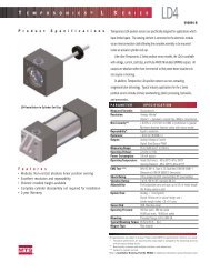
Model <strong>RF</strong> flexible housing option dimension referencesR-Series sensor with Model <strong>RF</strong> <strong>Flexible</strong> <strong>Housing</strong> <strong>Option</strong>Drawing is for reference only, contact applications engineering for tolerance specific information.Notes:1. Total sensor length tolerances are:+8 mm (0.3 in.)/-5mm (0.2 in.) up to 7600 mm (300 in.) stroke length.+15 mm ((0.6 in.)/-5 mm (0.2 in.) over 7600 mm (300 in.) stroke length.2. Tolerances of total length do not influence the measuring stroke length.Model <strong>RF</strong> <strong>Flexible</strong> <strong>Housing</strong> <strong>Option</strong> for R-Series <strong>Sensors</strong>Dimension References and Standard Magnet Selections97 mm (3.8 in.)Heat shrink sleeve10 mm (0.38 in.) 25 mm (0.98 in.)A6 mm (0.25 in.) 7 mm (0.29 in.)AFace sealO-Ring96 mm (3.8 in.) Rigid section 94 mm (3.70 in.)Dead zone13 mm(0.51 in.) dia.51 mm (2 in.)NullRed grommetSealPosition magnetThread 3/4 - 16 UNF - 3Aor M18 x 1.5SECTION A-AFigure 1. R-Series Model <strong>RF</strong> flexible housing dimension referenceStandard magnet selections (Model <strong>RF</strong>)POSITION MAGNET SELECTIONS (Drawing dimensions are for reference only)Magnet and magnet dimensions Description Part number4 HolesEach 4.3 mm (0.17 in.) dia.90° apart on24 mm (0.94 in.) dia.Standard ring magnetI.D.: 13.5 mm (0.53 in.)O.D.: 33 mm (1.3 in.)Thickness: 8 mm (0.3 in.)Operating temperature:- 40 °C to 100 °CRing magnetI.D.: 13.5 mm (0.53 in.)O.D.: 25.4 mm (1 in.)Thickness: 8 mm (0.3 in.)Operating temperature:- 40 °C to 100 °C201542-240053314 mm(0.55 in.)60°21 mm(0.81 in.)2 HolesEach 4.3 mm(0.17 in.) dia. on24 mm (0.94 in.) dia.25 mm(0.97 in.)Open-ring magnet, Style MI.D.: 13.5 mm (0.53 in.)O.D.: 33 mm (1.3 in.)Thickness: 8 mm (0.3 in.)Operating temperature:- 40 °C to 100 °CThis magnet may influence the sensorperformance specifications for someapplications.251416-2<strong>MTS</strong> <strong>Sensors</strong>3R-Series Temposonics ® Linear-Position <strong>Sensors</strong> - Model <strong>RF</strong> <strong>Flexible</strong> <strong>Housing</strong> <strong>Option</strong>Product Data Sheet, Document Part No.: 551081, Revision B 10/11
Model <strong>RF</strong> <strong>Flexible</strong> <strong>Housing</strong> <strong>Option</strong> for R-Series <strong>Sensors</strong>Dimension and Magnet Selection ReferencesPOSITION MAGNET SELECTIONS (Drawing dimensions are for reference only)Magnet and magnet dimensions dimensions Description Part numberThickness4.7 mm(0.185 in.)28 mm(1.1 in.) O.D.19.3 mm(0.76 in.) I.D.Ring magnetI.D.: 19.3 mm (0.76 in.)O.D.: 28 mm (1.1 in.)Thickness: 4.7 mm (0.185 in.)Operating temperature:- 40 °C to +100 °C4004241 of 4 holeseach 4.6 mm(0.18 in.) dia.90˚ apart on 41.3 mm(1.625 in.) dia.Large ring magnetI.D.: 19.05 mm (0.75 in.)O.D.: 63.5 mm (2.49 in.)Thickness: 9.5 mm (0.375 in.)Operating temperature:- 40 °C to +75 °C2015541 of 2 holes each, 4.5 mm(0.18 in.) dia. 120˚ aparton 41.3 mm (1.625 in.) dia.11.2 mm (0.44 in.) opening90˚ Cut outLarge ring magnetI.D.: 15.9 mm (0.63 in.)O.D.: 63.3 mm (2.49 in.)Thickness: 9.5 mm (0.38 in.)Operating temperature:- 40 °C to +75 °C20155311 mm(0.43 in.)19.5 mm(0.77 in.)4.5 mm (0.18 in.)6 mm (0.24 in.)20 mm (0.79 in.)Block magnet, Style LI.D.: 19.5 mm (0.77 in.)Width: 31 mm (1.22 in.)Thickness: 13.5 mm (0.53 in.)Operating temperature:- 40 °C to +75 °C2528872 mm(0.08 in.)radius31 mm(1.22 in.)13.5 mm(0.53 in.)This magnet may influence thesensor performance specificationsfor some applications.Sensor mounting and Installation referencesR-Series Model <strong>RF</strong> Sensor Mounting and installation <strong>Flexible</strong> installation in any position!The model <strong>RF</strong> flexible sensor housing can be mounted to provide straight or curvilinear measurements. The sensor's flexible housingrequires supports or anchoring to maintain proper alignment between the sensor rod and the magnet. Without proper alignment, thesensor's output signal can be interrupted or lost.A hex flange comes mounted on the sensor head having either U.S. customary threads (3/4 - 16 UNF inches) or metric threads (M18 x 1.5).The flange is secured to the sensor head by 2 metric screws (M4 x 59 mm, 2.5 mm hex socket head). The flange can be used, or removed,to best accommodate the installation requirements. If the sensor is mounted without the flange, the red grommet seal can be cut off toprovide a flush mounting surface for the sensor’s face seal O-Ring (shown in 'Figure 1' on page 3 and 'Figure 2' below).Temposonics ®R-SeriesRR-Series Temposonics ® Linear-Position <strong>Sensors</strong> - Model <strong>RF</strong> <strong>Flexible</strong> <strong>Housing</strong> <strong>Option</strong>Product Data Sheet, Document Part No.: 551081, Revision B 10/11 4<strong>MTS</strong> <strong>Sensors</strong>
®®Figure 2. Installation example for flush mounting with red grommet seal removed.Model <strong>RF</strong> <strong>Flexible</strong> <strong>Housing</strong> <strong>Option</strong> for R-Series <strong>Sensors</strong>Magnet Selection and Installation ReferencesTemposonics ®R-SeriesRRigid section96 mm (3.8 in.)200 mm (8 in.) min. radiusFigure 3. Installation example showing minimum bend radius for curvilinear measurements.Most applications require that the <strong>RF</strong> flexible sensor housing be supported, such as, placed inside a guide pipe made of non-ferrous material,straight or bent to the desired shape.Open-ring magnetOpen-ring magnetTemposonics ®R-SeriesRGuide pipe, 9.4 mm (0.37 in.) min. I.D.(non-ferrous material)Sensor rodGuide pipeFigure 4. Installation example using non-ferrous guide pipe (customer supplied).When installed inside the <strong>MTS</strong> half-inch O.D. pressure housing pipe, the <strong>RF</strong> flexible sensor housing is suitable for use in hydraulic cylinders,and can simplify installation where installation or mounting space is limited (see 'Figure 7').Half inch O.D. pressure pipe and flange (<strong>Option</strong>al)Pipe and Flange selectionsThe half inch O.D. pressure pipe with flange is designed specifically for R-Series sensors with the model <strong>RF</strong> flexible housing option. Thepressure pipe and flange provide protection from high pressures, as found in hydraulic cylinders, up to 5,000 psi static, 10,000 psi spike. Forlarge cylinders, using the half-inch O.D. pressure pipe requires a larger gun-drilled bore in the piston head/rod assembly. Typically, a 0.75inch bore is used to match the I.D. of the ring magnet used (e.g. part no.: 201554 or part no.: 400424).10 mm (0.39 in.)Flat-faced flangeBeginning of stroke‘Null’ position51 mm (2 in.) Stroke lengthEnd of stroke ‘Span’ positionDead zone107 mm (4.2 in.)‡Position MagnetFlange threadsRefer to ‘Table 1’ (A) Flange threads12.7 mm (0.50 in.) O.D.9.4 mm (0.37 in.) I.D.‡ (4.2 in. dead zone = 3.7 in. dead zone of <strong>RF</strong> sensor +0.5 in. gap)Figure 5. Style 'HL' pressure pipe (flat-faced flange shown with U.S. customary threads)<strong>MTS</strong> <strong>Sensors</strong>5R-Series Temposonics ® Linear-Position <strong>Sensors</strong> - Model <strong>RF</strong> <strong>Flexible</strong> <strong>Housing</strong> <strong>Option</strong>Product Data Sheet, Document Part No.: 551081, Revision B 10/11
5R Series R®R-Series Model <strong>RF</strong> <strong>Flexible</strong> <strong>Housing</strong> <strong>Option</strong>Pressure Pipe and Flange SelectionsHalf inch O.D. pressure housing pipe and Flange selections (Continued)Beginning of stroke‘Null’ position10 mm (0.39 in.)Raised-face flange51 mm (2 in.)O-Ring25.4 mm(1 in.)Position MagnetRefer to ‘Table 1’(A) Flange threadsRefer to ‘Table 1’(B) Dimensions2.5 mm (0.10 in.)Flange threadsRefer to ‘Table 1’ (A) Flange threads25 mm (0.98 in.)Figure 6. Style 'HP' pressure pipe (raised-face flange shown with U.S. customary threads)Refer to ‘Table 1’(C) DimensionsFlange type Description(A) Flangethreads (B) Dimensions (C) DimensionsHP US customary threads with raised-face flange 3/4" - 16 UNF-3A 1.75 in. 2 in.HL US customary threads with flat-faced flange 3/4" - 16 UNF-3A 1.75 in. 2 in.HD Metric threads with flat-faced flange M18 x 1.5 46 mm 53 mmTable 1. Flange options and specifications500 mm (19.5 in.) recommended300 mm (12 in.) minimumMagnet12.7 mm (0.50 in.) O.D.Pressure pipe and flange200 mm (8 in.) min. radiusModel <strong>RF</strong> flexible sensor being installed inthe optional 12.7 mm (0.50 in.) O.D. pressure pipe with flange,where installation space is limited.Red grommet sealFlange that is included withthe Model <strong>RF</strong> sensor is firstremoved by the installer.Temposonics ®R-Series <strong>RF</strong>igure 7.Installation example using optional 12.7 mm (0.50 in.) O.D. pressure pipe inside hydraulic cylinderR-Series Temposonics ® Linear-Position <strong>Sensors</strong> - Model <strong>RF</strong> <strong>Flexible</strong> <strong>Housing</strong> <strong>Option</strong>Product Data Sheet, Document Part No.: 551081, Revision B 10/11 6<strong>MTS</strong> <strong>Sensors</strong>
R-Series Model <strong>RF</strong> <strong>Flexible</strong> <strong>Housing</strong> <strong>Option</strong>Ordering InformationH1 2 3 4 5 6 7Half inch O.D. Pressure pipe anD flange Style = H 1-2HL= US customary threads, flat-facedflange and 1/2 inch pressure pipeHP= US customary threads,raised-faced flange and 1/2 inchpressure pipe,HD= Metric threads, flat-faced flangeand 1/2 inch pressure pipeSTROKE LENGTH = 3-7— — — — M = Millimeters(Encode in 5 mm increments)Stroke Length Notes:— — — . — U = Inches and tenths1. Half inch O.D. pressure pipe and flange stroke range = 255 mm (10 in.) to(Encode in 0.1 in. increments) 5840 mm (230 in.)2. Contact factory for longer lengths.Ordering examples:HL0120U = 1/2 inch O.D. pressure pipe with flat-faced flange, US customary threads, for a 12.0 inch stroke lengthHD1000M = 1/2 inch O.D. pressure pipe with flat-faced flange, metric threads, for a 1000 mm stroke lengthOrdering InformationR-Series Model <strong>RF</strong> <strong>Flexible</strong> <strong>Housing</strong> <strong>Option</strong><strong>RF</strong>1 2 3 4 5 6 7 8 9To complete the sensor model number, consult the specific orderinginformation page for the R-Series model you need.R-Series <strong>Housing</strong> MODEL = R F 1-2<strong>RF</strong>= <strong>Flexible</strong> styleMagnet must be ordered separately.SFlange Type = 3= US customary threads, flat-facedflangeM = Metric threads, flat-faced flangeSTROKE LENGTH = 4-9— — — — — M = Millimeters(Encode in 5 mm increments)— — — —. — U = Inches and tenths(Encode in 0.1 in. increments)Stroke Length Notes:1. <strong>Flexible</strong> housing style sensor (model <strong>RF</strong>) stroke range = 255 mm (10 in.) -10,060 mm (396 in.)2. Contact factory for longer lengths.Ordering Examples:<strong>RF</strong>S03937UD701S1B1100 = 393.7 in. stroke length for <strong>RF</strong> sensor with SSI output<strong>RF</strong>M10000MD631P102 = 10,000 mm stroke length for <strong>RF</strong> sensor with Profibus outputDocument Part Number: 551081, Revision B 10/11<strong>MTS</strong> and Temposonics are registered trademarks of <strong>MTS</strong> Systems Corporation.All other trademarks are the property of their respective owners.Printed in USA. Copyright © 2011 <strong>MTS</strong> Systems Corporation. All Rights Reserved in all media.<strong>MTS</strong> Systems Corporation<strong>Sensors</strong> Division<strong>MTS</strong> Sensor TechnologieGmbH & Co. KG<strong>MTS</strong> <strong>Sensors</strong> TechnologyCorporationSENSORS®3001 Sheldon DriveCary, North Carolina27513, USATel.: +1-800-633-7609Fax: +1-919-677-2343+1-800-498-4442e-mail: sensorsinfo@mts.comhttp://www.mtssensors.comAuf dem Schüffel 9D - 58513 Lüdenscheid, GermanyTel.: +49-2351-9587-0Fax: +49-2351-56491e-mail: info@mtssensor.dehttp://www.mtssensor.de737 Aihara-cho, Machida-shiTokyo 194-0211, JapanTel.: +81-42-775-3838Fax: +81-42-775-5516e-mail: info@mtssensor.co.jphttp://www.mtssensor.co.jp