Calculating and Accommodating Pipe Line Thermal Growth - Victaulic
Calculating and Accommodating Pipe Line Thermal Growth - Victaulic
Calculating and Accommodating Pipe Line Thermal Growth - Victaulic
- No tags were found...

You also want an ePaper? Increase the reach of your titles
YUMPU automatically turns print PDFs into web optimized ePapers that Google loves.
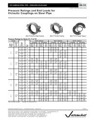
RGROOVED PIPING SYSTEM – DESIGN DATA26.02VICTAULIC ® IS AN ISO 9001 CERTIFIED COMPANY<strong>Calculating</strong> <strong>and</strong> <strong>Accommodating</strong> <strong>Pipe</strong> <strong>Line</strong> <strong>Thermal</strong> <strong>Growth</strong>All materials, including pipe, machinery, structures <strong>and</strong> buildingsexperience dimension changes as a result of changes intemperatures. This report covers considerations foraccommodating thermal expansion <strong>and</strong> contraction. Movementdue to other causes (e.g.: seismic, etc.) must be added to pipe linethermal growth. <strong>Pipe</strong> subjected to temperature changes will beplaced in a condition of stress, exerting potentially damagingreactive forces <strong>and</strong> moments on components or equipment.Three common methods of accommodating this pipe movementare to 1) provide an expansion joint; 2) allow the system to “freefloat”whereby the pipe would be allowed to move in a desireddirection through the use of anchoring <strong>and</strong>/or guidance, ifnecessary, taking into account the capability of branch connectionor changes in direction which may have resultant harmful bendingmoments; or 3) utilize the linear movement/deflection capabilities offlexible grooved couplings.The selection of either of these methods is dependent on the typeof piping system <strong>and</strong> the designer's preference. Since it isimpossible to predict all system designs, it is the intent here to callattention to the mechanical advantages of the grooved pipingmethod <strong>and</strong> how it can be used to the piping system designer'sbenefit. These examples are presented to stimulate thought <strong>and</strong>should not be considered as recommendations for a specificsystem.The first step in accommodating thermal movement is to computethe exact change in the linear length of the piping system over thedistance of interest, along with a suitable safety factor. The actualexpansion of 100-foot pipe lengths has been computed at differenttemperatures for the most common piping materials (carbon steel,stainless steel <strong>and</strong> copper tubing) <strong>and</strong> are shown in Table 1. Thesevalues should not be applied to pipe of alternate materials as theywill vary. Expansion coefficients may vary 5% or more whenobtained from different sources <strong>and</strong> should be taken into account.An example illustrating the use of Table 1 follows:Given: 240-foot long carbon steel pipeMaximum operating temperature = 220°F (104°C)Minimum operating temperature = 40°F (4°C)Temperature at time of installation = 80°F (26°C)Note: To assure the maximum life for the serviceintended, proper gasket selection is essential.Reference should always be made to the latest<strong>Victaulic</strong> Gasket Selection Guide forrecommendations.Calculation: From Table 1, carbon steel pipe expansion220°F (104°C) 1.680" per 100 ft. of carbon steel pipe40°F (4°C) 0.300" per 100 ft. of carbon steel pipeDifference: 1.380" per 100 ft. of carbon steel pipe fortemperatures 40°F to 220°FTherefore, 240-feet of pipe = 240 (1.380) = 3.312"100Installation to cold condition (80°F to 40°F)80°F (26°C) 0.580" per 100 ft.40°F (4°C) 0.300" per 100 ft.Difference: 0.280" per 100 ft. or 0.672" per 240 ft.Installation to hot condition (80°F to 220°F)220°F(104°C) 1.680" per 100 ft.80°F(26°C) 0.580" per 100 ft.Difference: 1.100" per 100 ft. or 2.640" per 240 ft.Therefore, the expansion joint is to be set up with at least thecapability to allow 0.672" of pipe contraction <strong>and</strong> at least 2.640" ofpipe expansion when installed at 80°F (26°C).TABLE 1<strong>Thermal</strong> Expansionof <strong>Pipe</strong>Inches per 100 ft.mm per 100 metersCarbonStain.Steel Copper Steel<strong>Thermal</strong> Expansionof <strong>Pipe</strong>Inches per 100 ft.mm per 100 metersTemp.°F/°CTemp.°F/°CCarbonSteel CopperStain.Steel–40 –0.288 –0.421 –0.461 180 1.360 2.051 2.074–40 –24,0 –35,1 –38,4 82 113,2 170,9 172,9–20 –0.145 –0.210 – 0.230 200 1.520 2.296 2.304–28 –12,1 –17,4 –19,0 93 126,6 191,3 191,90 0 0 0 212 1.610 2.428 2.442–17 0 0 0 100 134,2 202,4 203,420 0.148 0.238 0.230 220 1.680 2.516 2.534–6 12,5 19,7 19,0 104 140,1 209,7 211,332 0.230 0.366 0.369 230 1.760 2.636 2.6500 19,0 30,5 30,8 110 146,7 219,8 220,840 0.300 0.451 0.461 260 2.020 — —4 24,9 37,7 38,4 126 168,3 — —60 0.448 0.684 0.691 280 2.180 — —15 37,4 57,1 57,7 137 181,8 — —80 0.580 0.896 0.922 300 2.350 — —26 48,2 74,8 76,8 148 195,9 — —100 0.753 1.134 1.152 320 2.530 — —37 62,7 94,5 96,1 160 211,0 — —120 0.910 1.366 1.382 340 2.700 — —48 75,8 113,9 115,2 171 225,1 — —140 1.064 1.590 1.613 350 2.790 — —60 88,6 132,6 134,5 176 232,6 — —160 1.200 1.804 1.84371 100,1 150,3 153,6This 3.312" of movement should have a suitable safety factorapplied, which varies as determined by the system designer, toaccount for any errors in predicting operating extremes, etc. Theseexamples were calculated without a safety factor applied.To determine the positioning of the expansion joint at the time ofinstallation:® REGISTERED TRADEMARK OF VICTAULIC – © COPYRIGHT 1998 VICTAULIC – PRINTED IN U.S.A. 1554 REV C<strong>Victaulic</strong> Company of America • Phone: 1-800-PICK-VIC (1-800-742-5842) • Fax: 610-250-8817 • e-mail:pickvic@victaulic.com<strong>Victaulic</strong> Company of Canada • Phone: 905-884-7444 • Fax: 905-884-9774 • e-mail: viccanada@victaulic.com<strong>Victaulic</strong> Europe • Phone:32-9-381-1500 • Fax: 32-9-380-4438 • e-mail: viceuro@victaulic.be<strong>Victaulic</strong> America Latina • Phone: 610-559-3300 • Fax: 610-559-3608 • e-mail: vical@victaulic.com<strong>Victaulic</strong> Asia Pacific • Phone: 65-6235-3035 • Fax: 65-6235-0535 • e-mail: vicap@victaulic.com
26.02ACCOMMODATING PIPE THERMAL GROWTH<strong>Victaulic</strong> offers the designer basic methods for accommodatingpipe movement due to contraction <strong>and</strong>/or expansion.1. <strong>Victaulic</strong> Style 150 Mover ® Expansion Joint2. Free-Floating System3. <strong>Victaulic</strong> flexible grooved couplings utilizing their linearmovement <strong>and</strong> deflection capabilities.4. Expansion loops utilizing <strong>Victaulic</strong> flexible couplings <strong>and</strong>fittings.These devices offer economical <strong>and</strong> attractive solutions toproblems of thermal movements. The following sections provideproduct information <strong>and</strong> suggestions which show the mechanicaladvantages of the grooved piping method. Since it is impossibleto predict all system designs, it should be noted that thesesuggestions are not considered as recommendations for aspecific system.1. <strong>Victaulic</strong> Style 150 Mover ® Expansion JointThe <strong>Victaulic</strong> Style 150 Mover Expansion Joint is a slip-typeexpansion joint which can provide up to 3" (76 mm) axialmovement, accommodating pipe expansion <strong>and</strong>/or contraction.(See 09.04)As with all types of expansion joints, the designer should guardagainst damaging conditions for which these devices cannotaccommodate, such as temperatures or pressures outside theproduct recommended range or motions which exceed theproduct’s capability.For proper operation of the expansion joint, the piping systemshould be divided into separate expansion/contraction sectionswith suitable supports, guides <strong>and</strong> anchors to direct axial pipemovement.Anchors can be classified as main or intermediate for thepurpose of force analysis. Main anchors are installed at terminalpoints, major branch connections, or changes of pipingdirection. The forces acting on a main anchor will be due topressure thrust, velocity flow <strong>and</strong> friction of alignment guides<strong>and</strong> weight support devices.Intermediate anchors are installed in long runs to divide theminto smaller exp<strong>and</strong>ing sections to facilitate using less complexexpansion joints. The force acting on the intermediate anchor isdue to friction at guides, weight of supports or hangers, <strong>and</strong> theactivation force required to compress or exp<strong>and</strong> an expansionjoint.<strong>Pipe</strong> alignment guides are essential to ensure axial movementof the expansion joint. Whenever possible, the expansion jointshould be located adjacent to an anchor within four (4) pipediameters. The first <strong>and</strong> second alignment guides on theopposite side of the expansion joint should be located amaximum distance of four (4) <strong>and</strong> fourteen (14) pipe diameters,respectively. Additional intermediate guides may be requiredthroughout the system for pipe alignment. If the expansion jointcannot be located adjacent to an anchor, install guides on bothsides of the unit, as mentioned.THE DATA PROVIDED IS INTENDED FOR USE AS ANAID TO QUALIFIED DESIGNERS WHEN PRODUCTSARE INSTALLED IN ACCORDANCE WITH THELATEST AVAILABLE VICTAULIC PRODUCT DATA.TABLE 2RECOMMENDED PIPE ALIGNMENT GUIDE SPACING<strong>Pipe</strong> SizeMaximumApproximateNominalDiameterInches/mmActualOutsideDiameterInches/mmDistanceto 1st Guideor AnchorInches/mmDistanceBetween1st to 2nd GuideInches/mm1 1.315 4" 1' - 4"25 33,7 101,6 406,41 1 / 4 1.660 5" 1' - 5"32 42,4 127,0 431,81 1 / 2 1.900 6" 1' - 9"40 48,3 152,4 533,42 2.375 8" 2' - 4"50 60,3 203,2 711,22 1 / 2 2.875 10" 2' - 11"65 73,0 254,0 889,03 3.500 1' - 0" 3' - 6"80 88,9 304,8 1066,83 1 / 2 4.000 1' - 2" 4' - 1"90 101,6 355,6 1244,64 4.500 1' - 4" 4' - 8"100 114,3 406,4 1422,45 5.563 1' - 8" 5' - 8"125 141,3 508,0 1727,26 6.625 2' - 0" 7' - 0"150 168,3 609,6 2133,68 8.625 2' - 8" 9' - 4"200 219,1 812,8 2844,810 10.750 3' - 4" 11' - 8"250 273,0 1016,0 3556,012 12.750 4' - 0" 14' - 0"300 323,9 1219,2 4267,214 14.000 4' - 8" 16' - 4"350 355,6 1422,4 4978,416 16.000 5' - 4" 18' - 8"400 406,4 1625,6 5689,618 18.000 6' - 0" 21' - 0"450 457,0 1828,8 6400,820 20.000 6' - 8" 23' - 4"500 508,0 2032,0 7112,024 24.000 8' - 0" 28' - 0"600 610,0 2438,4 8534,4IntermediateGuide2ndGuide14D1st"The Mover"1stGuideGuide4D2ndGuideSupportIntermediateGuide2 <strong>Calculating</strong> <strong>and</strong> <strong>Accommodating</strong> <strong>Pipe</strong> <strong>Line</strong> <strong>Thermal</strong> <strong>Growth</strong>
26.02In addition, where long length, low pressure applications mayrequire few intermediate alignment guides, the pipe weight,including any liquid contents, must be adequately supported.Recommended spacings are shown in the <strong>Victaulic</strong> I-100Pocket H<strong>and</strong>book <strong>and</strong> in the Design Data Section 26.01 of theGeneral Catalog.Figure 1 illustrates a typical application of expansion joints,anchors, <strong>and</strong> guides.Point AExpansionJointMain AnchorGuideBFigure 1IntermediateAnchorWhen installed, the “Mover” can provide compensation for 3"(76 mm) of axial pipe movement. This movement may be set tocompensate for pipe expansion, contraction, or somecombination as directed by the system requirements.Additionally, the movement caused by installation at atemperature other than the minimum or maximum operatingtemperature should be accounted for by adjusting theexpansion joint’s installed length.The activation forces required to fully compress <strong>Victaulic</strong>expansion joints are equivalent to the forces required toovercome approximately 15 psi (103 kPa) internal pressure. Theforces required will be similar for both the Style 150 MoverExpansion Joint <strong>and</strong> Style 155 Expansion Joint <strong>and</strong> aretabulated in Table 3 according to size.In pipe sizes where the Mover is not available, <strong>Victaulic</strong> offersour Style 155 Expansion Joints. Style 155 Expansion Joints area combination of couplings <strong>and</strong> short nipples, joined in t<strong>and</strong>emto provide increased expansion. The nipples are preciselygrooved to provide full linear allowance at each joint.The st<strong>and</strong>ard units are prepared with Style 77 or Style 75couplings <strong>and</strong> are assembled with nipples in the full openposition for full expansion. Also st<strong>and</strong>ard units provide up to1.88" (47.752 mm) ( 3 / 4 - 3"/20 - 80 mm sizes) or 1.75" (44.45 mm)(4 - 24"/100 - 600 mm sizes) of axial movement. Style 155Expansion Joints with more or less axial movement capabilityare available simply by adding or removing coupling <strong>and</strong> nippleunits. For contraction services, units are fully compressed.Where expansion <strong>and</strong> contraction allowances are needed, thespacing will be set proportionally to the installation temperature<strong>and</strong> the temperature extremes (according to customerspecifications).<strong>Victaulic</strong> Style 155 Expansion Joints may be used as flexibleconnectors; however, they will not simultaneously provide fullexpansion <strong>and</strong> full deflection. Expansion Joints installedhorizontally require independent support to prevent deflectionwhich will reduce the available expansion.CΘTABLE 3NominalDiameterInches/mm<strong>Pipe</strong> SizeActualOutsideDiameterInches/mmActivation ForceLbs.N1 1.315 2025 33,7 891 1 / 2 1.900 4540 48,3 2002 2.375 7050 60,3 3123 3.500 14580 88,9 6454 4.500 240100 114,3 10686 6.625 520150 168,3 23148 8.625 880200 219,1 391610 10.750 1365250 273,0 607412 12.750 1915300 323,9 852214 14.000 2310350 355,6 1028016 16.000 3015400 406,4 1341718 18.000 3820450 457,0 1699920 20.000 4715500 508,0 2098224 24.000 6785600 610,0 301932. Free-Floating SystemFree-floating systems are piping systems which are allowed tothermally exp<strong>and</strong>/contract without the use of expansion joints,provided that this movement does not cause bending momentstresses at branch connections, or is not harmful to joints <strong>and</strong>changes in direction, or to parts of structures or otherequipment. This can be accomplished by r<strong>and</strong>omly installingjoints or, if desired, by installing guides to control the directionof movement. The effects of pressure thrusts must be taken intoaccount when utilizing flexible grooved couplings as the pipewill be moved to the full extent of the available pipe end gapswhen allowed to float.Pressure Zero<strong>Line</strong> Pressurized∆ LEnsure that branch connections <strong>and</strong> offsets are sufficiently longso that the maximum angular deflection of the coupling (shownin Performance Data for each coupling style) is never exceeded<strong>and</strong> that it can accommodate the anticipated total movement ofthe pipes. Otherwise, anchor the system <strong>and</strong> direct movements.Also ensure that adjacent pipes can move freely to provideanticipated movements.<strong>Calculating</strong> <strong>and</strong> <strong>Accommodating</strong> <strong>Pipe</strong> <strong>Line</strong> <strong>Thermal</strong> <strong>Growth</strong> 3
26.02Movement Dueto Pressure ThrustOffsetPlan View(Zero Pressure)Offsets have to be capable of deflecting sufficiently to preventharmful bending moments which would be induced at the jointsof the offset. Note, if the pipes were to exp<strong>and</strong> due to thermalchanges, then further growth of the pipes would also take placeat the ends.Angular deflection at butted or fully spaced joints is not possibleunless the ends of the pipes can shorten <strong>and</strong> grow as required.Unrestrained deflected joints will straighten up under the actionof axial pressure thrusts or other forces acting to pull pipesapart. If joints are to be maintained deflected, then lines must beanchored to restrain pressure thrusts <strong>and</strong> end pull forces,otherwise sufficient lateral force must be exerted to keep jointdeflected.FΘHangerLateralForcePlan View(Pressurized)Gross effect ofinadequate lateralrestraint on suspended system.(illustration exaggerated for clarity)Flexible couplings do not automatically provide for expansion orcontraction of piping. Always consider best setting for pipe endgaps. In anchored systems, gaps must be set to h<strong>and</strong>lecombinations of expansion <strong>and</strong> contraction. In free floatingsystems, offsets of sufficient length must be used toaccommodate movement without over-deflecting joints.GFULLY APARTExpansion OnlyLateral forces (F) will always act on deflected joints due tointernal pressure. A fully deflected joint will no longer becapable of providing the full linear movement normally availableat the joint.Joints DeflectedNo Expansion/ContractionAvailableFULLY BUTTEDContraction OnlyPARTIALLY GAPPEDExpansion <strong>and</strong> ContractionForExpansionForDeflectionEnsure anchorage <strong>and</strong> support is adequate. Use anchors todirect movement away from or to protect critical changes indirection, branch connections <strong>and</strong> structure. Spacing <strong>and</strong> typesof supports should be considered in accommodatinganticipated pipe movements. (Refer to the <strong>Victaulic</strong> I-100Pocket H<strong>and</strong>book or Section 26.01 of the General Catalog forsuggested hanger spacing.)The grooved piping method will not allow both maximum linearmovement <strong>and</strong> maximum angular movement simultaneously atthe same joint. If both are expected simultaneously, systemsshould be designed with sufficient joints to accommodate both,including allowance for recommended tolerances.For anchored systems, where pressure thrusts do not act tohold the joints in tension, or in systems where the joints havebeen intentionally deflected (e.g., curves), provide lateralrestraint to prevent movement of the pipes due to pressurethrusts acting at deflections. Lightweight hangers are notadequate in preventing sideways movement of pipes. It shouldbe anticipated that small deflections will occur in all straightlines <strong>and</strong> side thrusts will be exerted on the joints.= Anchor = Lateral ResistanceMovement in piping systems due to thermal changes can beaccommodated with the grooved piping method. Sufficientflexible joints must be available to accommodate anticipatedmovement, including Movement Tolerance. If anticipatedmovement will be greater than provided by the total number ofjoints in the system, additional expansion in the form of a<strong>Victaulic</strong> Style 150 Mover or Style 155 Expansion Joint shouldbe used (Refer to Section 09.04 or 09.05).<strong>Calculating</strong> <strong>and</strong> <strong>Accommodating</strong> <strong>Pipe</strong> <strong>Line</strong> <strong>Thermal</strong> <strong>Growth</strong> 5
26.02Example 1EXAMPLE: 400-foot (122 m) long, straight piping system; 6"(150 mm); 20-foot (6 m) r<strong>and</strong>om lengths; installed at 60° F(+16°C) (also lowest operating temperature); maximumoperating temperature of 180° F (+82°C). St<strong>and</strong>ard expansiontables show this system will give 3.7" (94 mm) total anticipatedmovement. (Refer to Section 26.02).20 Joints between anchor pointsX 1 / 4" Movement per coupling(cut grooved Style 77 Performance Data)5" Available Movement– 25% Movement Tolerance3.75"In the above example, Style 07 Zero-Flex Rigid Couplings couldhave been used <strong>and</strong> the expansion <strong>and</strong>/or contractionrequirement be made up with additional flexible couplings <strong>and</strong>/or Style 150, 155 Expansion Joints as needed.4. Expansion Loops Utilizing <strong>Victaulic</strong> Flexible Couplings <strong>and</strong>Fittings<strong>Victaulic</strong> offers the designer the advantage of using <strong>Victaulic</strong>flexible couplings <strong>and</strong> fittings in expansion loops withoutinducing stresses in the pipes, elbows or joints. The deflectioncapability of flexible couplings allows for thermal growth/contraction to be absorbed within the couplings at the elbowsas the thermal forces induce deflection. Also, it is important thatrigid couplings (<strong>Victaulic</strong> Style 07, HP-70) are not used onexpansion loops as these couplings are not designed toaccommodate angular deflection.A total of eight (8) <strong>Victaulic</strong> flexible couplings, four (4) <strong>Victaulic</strong>grooved 90° elbows <strong>and</strong> three (3) pipe spools are required tocomplete each expansion loop. Their orientation is as shown inFigure A. As system temperatures lower <strong>and</strong> the pipe runcontracts (see Figure B), the loop exp<strong>and</strong>s <strong>and</strong> the deflectioncapability of the couplings accommodate this movement. Assystem temperatures increase (see Figure C), the oppositeeffect occurs as the pipe run exp<strong>and</strong>s <strong>and</strong> the loop contractswith the couplings accommodating the deflection in theopposite direction.<strong>Victaulic</strong> Style 75,77, or 791 Coupling(8 Required)ABREF.XFIGURE AExpansion Loop<strong>Victaulic</strong> 90° Elbow(4 Required)A∆X/2XX EREF.∆X/2FIGURE C<strong>Thermal</strong> Expansion<strong>Pipe</strong>line Grows into Loop – Loop ContractsThe amount of thermal expansion/contraction, ∆X, should bedetermined by the system designer based on the length of piperun between anchors <strong>and</strong> the anticipated temperatures changefrom the installation temperature (see Table 1 for details). Theangular deflection available at each coupling is a designcharacteristic inherent to the coupling size <strong>and</strong> style <strong>and</strong> thetype of groove (cut or roll grooved). The length of theperpendicular branches of the loop (Dimension A) isdetermined by the amount of expected pipeline expansion/contraction (∆X) <strong>and</strong> the deflection available per joint.Dimension A should be the same on both sides of the loop. Thelength of the parallel branch of the expansion loop (DimensionB) is determined by ∆X, <strong>and</strong> it must be sufficiently long enoughto prevent the elbows at the pipe run from butting during thermalexpansion. It is recommended that Dimension B be at least 2"(50,8 mm) larger than ∆X.The designer can use Figures D <strong>and</strong> E titled “Expansion LoopDesign Utilizing <strong>Victaulic</strong> Flexible Couplings <strong>and</strong> Fittings” to aidin the design of expansion. These loops incorporate all of thedesign information for each size <strong>Victaulic</strong> Flexible Couplingincluding the angular movement tolerance as shown in Section3. The nominal pipe size <strong>and</strong> either the design thermalexpansion (∆X) or the length of perpendicular branches (A)must be known <strong>and</strong> the other can be determined. It is essentialfor a properly functioning expansion loop that it be installedwithout any coupling deflection <strong>and</strong> that the pipeline beproperly anchored <strong>and</strong> guided. Whenever possible, theexpansion loop should be located adjacent to an anchor withinfour (4) pipe diameters. The first <strong>and</strong> second alignment guideson the opposite side of the expansion loop should be located amaximum distance of four (4) <strong>and</strong> fourteen (14) pipe diameters,respectively. Additional intermediate guides may be requiredthroughout the system for pipe alignment. If the expansion loopcannot be located adjacent to an anchor, install guides on bothsides of the unit, as mentioned.Example: Using the parameters established in the previoussection’s example problem, 6" (150 mm) nominal pipe size <strong>and</strong>3.75" (95,2 mm) of total anticipated movement, refer to FiguresD <strong>and</strong> E to determine the length of perpendicular loop branchesfor both cut <strong>and</strong> roll groove pipe.∆X = 3.75" (95,2 mm)Nominal <strong>Pipe</strong> Size = 6" (150 mm)For Cut Groove <strong>Pipe</strong> (Figure D)A = 2.7 Ft. (0,82 m) MinimumFor Roll Groove <strong>Pipe</strong> (Figure E)A = 5.4 Ft. (1,65 m) Minimum∆X/2XX CREF.FIGURE B<strong>Thermal</strong> Contraction<strong>Pipe</strong>line Shrinks – Loop Exp<strong>and</strong>s∆X/26 <strong>Calculating</strong> <strong>and</strong> <strong>Accommodating</strong> <strong>Pipe</strong> <strong>Line</strong> <strong>Thermal</strong> <strong>Growth</strong>
FIGURE DEXPANSION LOOP DESIGN UTILIZING VICTAULIC FLEXIBLE COUPLINGS AND FITTINGS*VICTAULIC CUT GROOVED PIPE26.02Length of Perpendicular Branches of Expansion Loop (feet) (A)76.565.554.543.532.521.51.5Nominal <strong>Pipe</strong> Size(Inches)3¹⁄₂32¹⁄₂21¹⁄₂1¹⁄₄1³⁄₄Length of Perpendicular Branches of Expansion Loop (feet) (A)1413121110987654321Nominal <strong>Pipe</strong> Size(Inches)2420 &2218161412108654Length of Perpendicular Branches of Expansion Loop (feet) (A)014131211109876543211 2 3 4 5Design <strong>Thermal</strong> Expansion † (Inches)(∆ X)FIGURE EEXPANSION LOOP DESIGN UTILIZING VICTAULIC FLEXIBLE COUPLINGS AND FITTINGS*VICTAULIC ROLL GROOVED PIPENominal <strong>Pipe</strong> Size(Inches)3¹⁄₂32¹⁄₂21¹⁄₂1¹⁄₄1³⁄₄001 2 3 4 51 2 3 4 5Design <strong>Thermal</strong> Expansion † (Inches)Design <strong>Thermal</strong> Expansion † (Inches)(∆ X)(∆ X)* Based on pipe grooved in accordance with <strong>Victaulic</strong> specifications. † Valves include design tolerances: 50% reduction for sizes below 4"/25% reduction for sizes 4" <strong>and</strong> larger.Length of Perpendicular Branches of Expansion Loop (feet) (A)02826242220181614121086421 2 3 4 5Design <strong>Thermal</strong> Expansion † (Inches)(∆ X)Nominal <strong>Pipe</strong> Size(Inches)2420 &2218161412108654<strong>Calculating</strong> <strong>and</strong> <strong>Accommodating</strong> <strong>Pipe</strong> <strong>Line</strong> <strong>Thermal</strong> <strong>Growth</strong> 7
26.02To provide an expansion loop for the described system, the twobranches must be a minimum of 2.7 (0,82 m) feet <strong>and</strong> 5.4 (1,65m) feet long for cut <strong>and</strong> roll groove pipe, respectively. Theparallel branch of the expansion loop must be at least 2" (50,8mm) larger than ∆X.B = ∆X + 2B = 3.75" + 2" = 5.75" Minimum (95 mm + 54 = 4845 mm)In this case, a st<strong>and</strong>ard <strong>Victaulic</strong> No. 43 grooved x groovedadapter nipple with a 6" (152,4 mm) end-to-end dimension canbe utilized as the parallel branch for either cut or roll groovepipe.5. Expansion Loops for Joining Copper Tubing with <strong>Victaulic</strong>Copper Connection ProductsExpansion loops or “U” bends are frequently used toaccommodate the expansion <strong>and</strong>/or contraction of pipe linesdue to thermal changes. Copper tube, as does all pipingmaterial, exp<strong>and</strong>s <strong>and</strong> contracts with these temperaturechanges. Table 1 in Section 26.02 shows the actual expansionof 100-foot (30,5 m) pipe lengths for copper tubing. Calculationsfor the anticipated expansion/contraction can be obtained fromthe example shown in 26.02.The necessary length of copper tube expansion loop can becalculated from the following formulas (1) (2):L =3EDe-------------SCalculated Loop lengths for various expansions are shown in thetable below:TABLE 4Loop Length “L”, Inches/mm for Tube Sizes ShownExpansionInches/mm2 1 / 263,5376,24101,65127,06152,41/ 2 102 111 127 142 15512,7 2590,8 2819,4 3225,8 3606,8 3937,01 144 157 180 200 21925,4 3657,6 3987,8 4572,0 5080,0 5562,61 1 / 2 176 192 220 245 26838,1 4470,4 4876,8 5588,0 6223,0 6807,22 203 221 254 283 31050,8 5156,2 5613,4 6451,6 7188,2 7874,02 1 / 2 227 247 284 317 34663,5 5765,8 6273,8 7213,6 8051,8 8788,43 248 271 311 347 37976,2 6299,2 6883,4 7899,4 8813,8 9626,6NOTE: Expansion Loop should be located between two anchors <strong>and</strong> the pipe shouldbe guided so as to direct the movement into the loop.References:(1) Copper/Brass/Bronze Product H<strong>and</strong>book, CopperDevelopment Association, Inc.(2) Source book on Copper <strong>and</strong> Copper Alloys, AmericanSociety for Metals.L = Loop length, in inches, as shown in the figure below:<strong>Victaulic</strong> Style 606Coupling(8 Required)WL<strong>Victaulic</strong> No. 61090° Elbow(4 Required)H2H + W = LH = 2W5W = LE = modulus of elasticity of copper in psi = 15,600,000 psi(107 546 400 kPa)S = allowable stress of material in flexure, in psi = 6000 psi(41 364 kPa)D = outside diameter of copper tubing in inchese = amount of expansion to be absorbed, in inchesSimplifying the formula:L =88.32DeEste producto deberá ser fabricado por <strong>Victaulic</strong> Company. Todos los productos deberán instalarse de acuerdo con las instrucciones de instalación/montaje actuales de <strong>Victaulic</strong>.<strong>Victaulic</strong> se reserva el derecho de modificar las especificaciones y el diseño de los productos, así como los equipos estándar, sin aviso ni obligación alguna.8 <strong>Calculating</strong> <strong>and</strong> <strong>Accommodating</strong> <strong>Pipe</strong> <strong>Line</strong> <strong>Thermal</strong> <strong>Growth</strong>