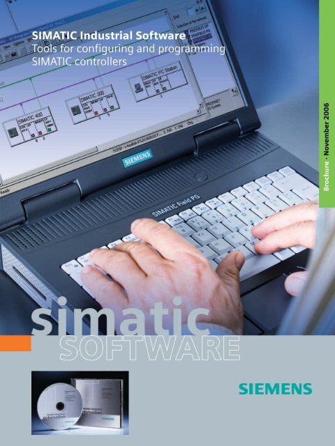
SIMATIC Industral Software - Tools for configuring and programming ...
SIMATIC Industral Software - Tools for configuring and programming ...
SIMATIC Industral Software - Tools for configuring and programming ...

Create successful ePaper yourself
Turn your PDF publications into a flip-book with our unique Google optimized e-Paper software.
1<br />
<strong>SIMATIC</strong> Industrial <strong>Software</strong><br />
<strong>Tools</strong> <strong>for</strong> <strong>configuring</strong> <strong>and</strong> <strong>programming</strong><br />
<strong>SIMATIC</strong> controllers<br />
Brochure · November 2006
Increase your competitiveness<br />
with Totally Integrated Automation<br />
In response to increasing international competitive pressures,<br />
it is more important now than ever be<strong>for</strong>e that your<br />
company focuses on its core competence. The medium<br />
<strong>and</strong> long-term strategic focus on future-oriented automation<br />
concepts will then become the key factor in lasting<br />
success.<br />
Siemens offers Totally Integrated Automation (TIA) as the<br />
perfect basis <strong>for</strong> this – <strong>for</strong> all sectors from inbound logistics to<br />
outbound logistics. Thanks to the unique system-wide integration<br />
of TIA, you can profit from the unparalleled interoperation<br />
of all our products <strong>and</strong> systems – spanning even different generations.<br />
This enables you to protect your investment <strong>and</strong>, at<br />
the same time, profit from future developments.<br />
2 Increase your competitiveness with Totally Integrated Automation<br />
<strong>SIMATIC</strong>, as the core of Totally Integrated Automation, comprises<br />
numerous st<strong>and</strong>ardized products <strong>and</strong> systems.<br />
The software plays a central role.<br />
<strong>SIMATIC</strong> Industrial <strong>Software</strong> supports all phases of the production<br />
lifecycle <strong>and</strong> makes a significant contribution towards<br />
increased productivity not just in the engineering phase, but<br />
also <strong>for</strong> maintenance, servicing, modification <strong>and</strong> adaptation.<br />
Read on to discover exactly how you can save time <strong>and</strong> costs<br />
by using <strong>SIMATIC</strong> Industrial <strong>Software</strong>.
Contents<br />
St<strong>and</strong>ard tools<br />
STEP 7 Professional. . . . . . . . . . . . . . . . . . . . . . . . . . 5<br />
STEP 7 Basis. . . . . . . . . . . . . . . . . . . . . . . . . . . . . . . . 6<br />
STEP 7 New functions. . . . . . . . . . . . . . . . . . . . . . . 10<br />
Engineering tools<br />
S7-SCL . . . . . . . . . . . . . . . . . . . . . . . . . . . . . . . . . . . 11<br />
S7-GRAPH . . . . . . . . . . . . . . . . . . . . . . . . . . . . . . . . 12<br />
S7-PLCSIM . . . . . . . . . . . . . . . . . . . . . . . . . . . . . . . . 13<br />
S7-HiGraph . . . . . . . . . . . . . . . . . . . . . . . . . . . . . . . 14<br />
CFC . . . . . . . . . . . . . . . . . . . . . . . . . . . . . . . . . . . . . 15<br />
Control configuration<br />
St<strong>and</strong>ard PID Control . . . . . . . . . . . . . . . . . . . . . . . 16<br />
Modular PID Control. . . . . . . . . . . . . . . . . . . . . . . . 17<br />
Diagnostics<br />
S7-PDIAG . . . . . . . . . . . . . . . . . . . . . . . . . . . . . . . . . 18<br />
TeleService . . . . . . . . . . . . . . . . . . . . . . . . . . . . . . . 21<br />
Configuration <strong>for</strong> Component Based Automation<br />
<strong>SIMATIC</strong> iMap . . . . . . . . . . . . . . . . . . . . . . . . . . . . . 22<br />
Licensing . . . . . . . . . . . . . . . . . . . . . . . . . . . . . . . . . 24<br />
<strong>Software</strong> Update Service . . . . . . . . . . . . . . . . . . . . 24<br />
Premium Studio . . . . . . . . . . . . . . . . . . . . . . . . . . . 25<br />
<strong>SIMATIC</strong> PG . . . . . . . . . . . . . . . . . . . . . . . . . . . . . . . 26<br />
Solution Partners . . . . . . . . . . . . . . . . . . . . . . . . . . 27<br />
Contents 3
<strong>SIMATIC</strong> Industrial <strong>Software</strong><br />
Increased productivity <strong>for</strong> your engineering workflow<br />
In many plants, engineering <strong>and</strong> commissioning costs represent<br />
the main expense factor. This is due to more complex <strong>and</strong><br />
quickly changing plant structures <strong>and</strong> the increased use of distributed<br />
intelligence. The user's challenge is to generate optimum<br />
automation solutions while simultaneously increasing<br />
the productivity throughout all engineering workflow phases.<br />
The engineering software is becoming increasingly important<br />
in this case. It must not only support engineering during the<br />
development phase, but also maintenance, servicing, modifications<br />
<strong>and</strong> adaptations. The strengths of the <strong>SIMATIC</strong> Industrial<br />
<strong>Software</strong> lie, in particular, in this support throughout the<br />
complete engineering workflow.<br />
The right tools <strong>for</strong> any application<br />
Every project includes various individual tasks to complete –<br />
from simple logic operations to complex control <strong>and</strong> data<br />
management tasks. Each requires maximum efficiency.<br />
<strong>SIMATIC</strong> Industrial <strong>Software</strong> provides an integrated engineering<br />
environment with first-class tools <strong>for</strong> the widest range of<br />
modes of operation <strong>and</strong> applications. These tools are based on<br />
an integrated system, offer open interfaces, generate reusable<br />
blocks <strong>and</strong> there<strong>for</strong>e save time.<br />
<strong>Software</strong> <strong>for</strong> PLC- <strong>and</strong> PC-based controllers<br />
STEP 7 can not only be used to program <strong>and</strong> configure programmable<br />
logic controllers, but also PC-based automation<br />
systems. The user can there<strong>for</strong>e select any hardware plat<strong>for</strong>m<br />
<strong>and</strong> use the same software even <strong>for</strong> mixed configurations.<br />
<strong>SIMATIC</strong> Field PG M – the ideal industrial notebook<br />
<strong>SIMATIC</strong> <strong>programming</strong> devices are the first choice when it<br />
comes to <strong>configuring</strong> <strong>and</strong> <strong>programming</strong> <strong>SIMATIC</strong> Industrial<br />
<strong>Software</strong>.<br />
The <strong>SIMATIC</strong> Field PG M distinguishes itself by its wireless technology,<br />
powerful Intel Pentium M processor, large display <strong>and</strong><br />
integral data backup concept. In addition, the new device has<br />
a long battery life, large working memory <strong>and</strong> all common interfaces<br />
<strong>for</strong> industrial applications.<br />
4 <strong>SIMATIC</strong> Industrial <strong>Software</strong><br />
<strong>SIMATIC</strong> Industrial <strong>Software</strong> –<br />
Highlights<br />
■ Intuitive operation <strong>and</strong> use of st<strong>and</strong>ard languages<br />
make it easy <strong>for</strong> programmers <strong>and</strong> maintenance<br />
personnel to familiarize themselves with the software.<br />
■ Design <strong>and</strong> implementation times are shortened<br />
by structured, process-oriented <strong>programming</strong><br />
methodology.<br />
■ The costs of subsequent projects are reduced because<br />
blocks are easy to reuse.<br />
■ The option to configure rather than program<br />
reduces the work load.<br />
■ The common engineering environment <strong>for</strong> PLC <strong>and</strong><br />
PC-based solutions makes user software portable.<br />
■ Efficient process diagnostics increase plant availability
St<strong>and</strong>ard tools<br />
STEP 7 Professional<br />
The complete package at an af<strong>for</strong>dable price<br />
STEP 7 is the most recognized <strong>and</strong> widely used <strong>programming</strong><br />
software worldwide in the industrial automation<br />
industry. Exp<strong>and</strong>ed to include additional important software<br />
tools, STEP 7 Professional is the tool that will greatly<br />
increase the productivity of your planning engineers.<br />
STEP 7 Professional includes other important languages in addition<br />
to STEP 7 Basis with the tried <strong>and</strong> tested <strong>programming</strong><br />
languages LAD, FBD <strong>and</strong> STL:<br />
■ S7-GRAPH to program sequential controls<br />
■ S7-SCL to program complex algorithms<br />
which were rated so important by programmers that they<br />
were also elevated to st<strong>and</strong>ard languages: IEC 61131-3 is the<br />
quality st<strong>and</strong>ard <strong>for</strong> <strong>programming</strong> software recognized worldwide.<br />
This st<strong>and</strong>ard is part of the curriculum of schools <strong>and</strong><br />
universities, so the know-how is widespread.<br />
S7-PLCSIM additionally provides STEP 7 Professional with a<br />
powerful engineering tool <strong>for</strong> program testing.<br />
Worldwide <strong>programming</strong> st<strong>and</strong>ard<br />
STEP 7 Professional is <strong>programming</strong> software <strong>for</strong> <strong>SIMATIC</strong> controllers<br />
which complies with the IEC 61131-3 st<strong>and</strong>ard.<br />
The international st<strong>and</strong>ard IEC 61131 is regarded as a worldwide<br />
<strong>and</strong> future-oriented st<strong>and</strong>ardization in the area of<br />
programmable logic controllers. It has been taken over as<br />
European st<strong>and</strong>ard EN 61131. It replaces several national<br />
st<strong>and</strong>ards.<br />
Worldwide st<strong>and</strong>ardization has the following advantages:<br />
■ Less software engineering overhead thanks to<br />
cross-company st<strong>and</strong>ardization.<br />
■ More efficient training <strong>and</strong> further training.<br />
■ Application software can be ported to devices of different<br />
manufacturers over the long term.<br />
Several expansions of the <strong>programming</strong> languages were implemented<br />
in compliance with the st<strong>and</strong>ards to offer the users<br />
optimum <strong>programming</strong> com<strong>for</strong>t <strong>and</strong> the full utilization of the<br />
functionality of the <strong>SIMATIC</strong> controllers.<br />
Higher productivity with<br />
STEP 7 Professional<br />
■ One package – all IEC languages:<br />
- STEP 7 with LAD, FBD, STL<br />
- S7-SCL<br />
- S7-GRAPH<br />
- ... <strong>and</strong> <strong>for</strong> offline testing: S7-PLCSIM<br />
■ Lower package price<br />
■ Low outlay <strong>for</strong> installation <strong>and</strong> updating<br />
■ Engineering workplaces with the same basic setup<br />
increase productivity:<br />
- Every employee working on the project<br />
can work on any device.<br />
- Every employee uses the tool, on which<br />
he/she can be the most productive.<br />
PLCopen: The organization<br />
Different manufacturers <strong>and</strong> users of control <strong>and</strong> <strong>programming</strong><br />
systems have founded the international organization PL-<br />
Copen, which promotes the use <strong>and</strong> distribution of <strong>programming</strong><br />
in accordance with IEC 61131. PLCopen aims to make<br />
application software portable between the hardware of different<br />
manufacturers.<br />
Siemens is actively participating in PLCopen <strong>and</strong> has introduced<br />
PLC <strong>programming</strong> to IEC 61131.<br />
The certification of <strong>programming</strong> systems from different manufacturers<br />
is an important prerequisite <strong>for</strong> making software<br />
portable. To allow this, the st<strong>and</strong>ard compliance classes were<br />
redefined by PLCopen:<br />
■ Base level<br />
■ Con<strong>for</strong>mity level<br />
■ Reusability level.<br />
Independent institutes carry out the test procedures <strong>and</strong> issue<br />
the respective certificates. Siemens has been awarded the<br />
base level certificate <strong>for</strong> S7-GRAPH (SFC) <strong>and</strong> the base level<br />
<strong>and</strong> reusability level certificate <strong>for</strong> S7-SCL (ST).<br />
St<strong>and</strong>ard tools 5
STEP 7 Basis<br />
Structured <strong>programming</strong><br />
STEP 7 Basis is the universal <strong>programming</strong> software <strong>for</strong><br />
<strong>configuring</strong> <strong>and</strong> <strong>programming</strong> <strong>SIMATIC</strong> controllers.<br />
The software supports the user throughout all phases of<br />
automation solutions – from the creation process to plant<br />
failure diagnostics.<br />
The essential characteristic of <strong>SIMATIC</strong> software <strong>and</strong> there<strong>for</strong>e<br />
– in addition to STEP 7 Basis – STEP 7 Professional is its clear<br />
structure.<br />
In the case of comprehensive programs, it is recommended<br />
<strong>and</strong> sometimes necessary to divide the program into individual<br />
program sections. The program sections should be program<br />
parts that are self-contained <strong>and</strong> that have a technological or<br />
functional correlation. These program parts are called program<br />
blocks. A block is a part of the user program that is defined<br />
by its function, structure or application.<br />
Elements of a user program<br />
User programs consist of the following elements:<br />
■ Organization blocks (OB)<br />
Organization blocks determine the structure of user programs.<br />
They represent the interface between the operating<br />
system <strong>and</strong> user program. They control the start-up behavior<br />
of the automation system, cyclic <strong>and</strong> interrupt-driven<br />
program execution <strong>and</strong> fault h<strong>and</strong>ling.<br />
■ Function blocks (FB), Functions (FC)<br />
- Function blocks are code blocks which contain the actual<br />
program. They have an assigned data block in which the<br />
input <strong>and</strong> output parameters as well as static data are<br />
stored. Thus the FBs can maintain the processed values<br />
throughout several cycles.<br />
- Functions have no assigned data block; when called, they<br />
always require current input values. They supply their<br />
function result after every call.<br />
- FBs <strong>and</strong> FCs can be self-programmed. The display of selfprogrammed<br />
blocks can also be suppressed. This is of<br />
interest, <strong>for</strong> example, to machine manufacturers to<br />
protect their know-how. FBs <strong>and</strong> FCs are there<strong>for</strong>e represented<br />
as blackboxes, since the user does not need to<br />
know how their functions were implemented.<br />
Libraries with special, pre-generated blocks that only<br />
need to be interconnected, are available as an option,<br />
<strong>for</strong> example, IEC functions, controllers <strong>and</strong> blocks <strong>for</strong><br />
converting <strong>SIMATIC</strong> S5 <strong>and</strong> 505 programs.<br />
6 St<strong>and</strong>ard tools<br />
Savings potential<br />
■ Even comprehensive programs can be programmed in<br />
a clear manner.<br />
■ Third parties that access structured programs <strong>for</strong><br />
service, maintenance or a later modification are better<br />
able to underst<strong>and</strong> <strong>and</strong> work with the program.<br />
Program testing may be per<strong>for</strong>med in steps.<br />
■ Program sections can be st<strong>and</strong>ardized <strong>and</strong> re-used.<br />
■ Data blocks (DBs)<br />
Data blocks are data storage areas that contain user data.<br />
They can be assigned to individual function blocks or the<br />
complete project.<br />
■ System functions (SFCs) <strong>and</strong> system function<br />
blocks (SFBs)<br />
Some functions that are repeatedly required are integrated<br />
into the operating system of the S7-CPUs <strong>and</strong> can be called<br />
from there. Some of these functions are, <strong>for</strong> example, communication<br />
functions, clock functions <strong>and</strong> operating hours<br />
counter, or the transfer of data records. The system<br />
functions/system function blocks are supplied as a library<br />
with STEP 7 <strong>for</strong> offline <strong>programming</strong>.<br />
Structure of a user program
STEP 7 Basis<br />
Universal development environment <strong>for</strong> <strong>SIMATIC</strong><br />
STEP 7 Basis contains numerous tools <strong>and</strong> functions <strong>for</strong> the<br />
most varied tasks in an automation project. The <strong>programming</strong><br />
languages LAD, FBD <strong>and</strong> STL meet the international<br />
IEC 61131-3 st<strong>and</strong>ard.<br />
The main components of STEP 7 Basis are:<br />
■ Program editor <strong>for</strong> developing <strong>and</strong> testing the user<br />
program in the <strong>programming</strong> languages LAD, FBD or STL<br />
■ Hardware configuration <strong>for</strong> <strong>configuring</strong> <strong>and</strong> parameterizing<br />
the hardware<br />
■ NetPro <strong>for</strong> setting up a data transfer over<br />
MPI or PROFIBUS/Ethernet<br />
■ Integrated hardware diagnostics; <strong>for</strong> obtaining an overview<br />
of the automation system status<br />
■ PID control <strong>and</strong> PID temperature control <strong>for</strong> parameterizing<br />
simple PID or temperature controllers<br />
■ <strong>SIMATIC</strong> Manager <strong>for</strong> administrating all tools <strong>and</strong> data of an<br />
automation project<br />
■ Creating programs <strong>for</strong> highly available controllers<br />
■ Open comm<strong>and</strong> interface <strong>for</strong> importing/exporting<br />
data from other Windows tools.<br />
Program editor<br />
The program editor is the <strong>programming</strong> interface <strong>for</strong> the user<br />
program. The user can program in the STL (statement list),<br />
FBD (function block diagram), <strong>and</strong> LAD (ladder diagram)<br />
<strong>programming</strong> languages. The individual languages can be<br />
generally combined <strong>and</strong> merged.<br />
Part of a function block programmed in LAD<br />
The representation of the program in the LAD editor is similar to a circuit<br />
diagram. The individual elements are arranged in sequence or parallel to<br />
each other.<br />
Hardware configuration<br />
The CPUs <strong>and</strong> modules of the <strong>SIMATIC</strong> don't need mechanical<br />
switches <strong>and</strong> adjusting screws anymore. All settings are implemented<br />
centrally using the software. To do so, the hardware<br />
(also central <strong>and</strong> distributed inputs/outputs) is configured <strong>and</strong><br />
parameterized in the HW Config (hardware configuration)<br />
tool.<br />
Special functions of HW Config are:<br />
■ Internet link<br />
The most current in<strong>for</strong>mation regarding the hardware used<br />
can be called up whenever required by accessing the product<br />
support in<strong>for</strong>mation on the Internet. Technical data,<br />
FAQs or documentation on the modules used can be accessed<br />
directly via the help system of HW Config. New hardware<br />
components can be integrated directly into STEP 7 via<br />
the Internet without having to install a comprehensive<br />
service pack.<br />
■ Configuration in RUN (CiR)<br />
With CiR certain modifications of the hardware configuration<br />
in a plant can be implemented while operation is ongoing.<br />
The process execution is interrupted <strong>for</strong> a maximum<br />
of one second. To do so, CiR elements are defined during<br />
hardware configuration which then in operating mode RUN<br />
can be substituted step by step by real objects. Prerequisite<br />
is the use of an S7-400 or S7-400H CPU.<br />
Part of a function block programmed in FBD<br />
The program consists of individual program elements. They are represented by<br />
boxes. The links between these boxes represent the binary signal flow. In this<br />
case, a control system flowchart in monitoring mode is shown.<br />
St<strong>and</strong>ard tools 7
STEP 7 Basis<br />
Universal development environment <strong>for</strong> <strong>SIMATIC</strong><br />
Calling up detailed in<strong>for</strong>mation over the Internet<br />
NetPro<br />
The STEP 7 tool NetPro enables the configuration of the system<br />
communication. Here the communication links between<br />
individual stations is configured graphically <strong>and</strong> very vividly.<br />
All required drivers <strong>for</strong> PROFINET <strong>and</strong> PROFIBUS CPs (NCM) are<br />
supplied with NetPro.<br />
Graphic configuration of the communication links in NetPro<br />
8 St<strong>and</strong>ard tools<br />
Hardware diagnostics<br />
Hardware diagnostics <strong>for</strong> obtaining an overview of the current<br />
automation system status. To do so, the hardware components<br />
generate corresponding diagnostics in<strong>for</strong>mation that<br />
can be analyzed in STEP7. Faults in components are also<br />
scanned here that are linked to the PLC over PROFIBUS.<br />
One function of the hardware diagnostics is, <strong>for</strong> example:<br />
■ Reporting system errors:<br />
The function "Report system error" offers the convenient<br />
possibility of displaying the diagnostics in<strong>for</strong>mation provided<br />
by the hardware components of the PLC in the <strong>for</strong>m<br />
of signals. The required blocks <strong>and</strong> message texts are automatically<br />
generated by STEP 7. They only need to be loaded<br />
into the CPU. The transfer of diagnostics texts to connected<br />
<strong>SIMATIC</strong> HMI devices does not entail any <strong>programming</strong><br />
overhead.<br />
Since STEP 7 <strong>and</strong> the <strong>SIMATIC</strong> HMI systems <strong>SIMATIC</strong> WinCC<br />
<strong>and</strong> WinCC flexible use a common database the same plain<br />
text error messages will be displayed in STEP 7 <strong>and</strong> on the<br />
HMI system.<br />
■ Detailed system diagnostics with the PG:<br />
Detailed analysis of errors is possible with the <strong>programming</strong><br />
device. The diagnostics function supports configuration<br />
<strong>and</strong> commissioning, but is also available during operation.<br />
- Summary diagnostics: The topology of the control is<br />
displayed graphically in a window. The module status is<br />
displayed in this window providing additional in<strong>for</strong>mation<br />
at a glance without the need to switch to other tools.<br />
- Detailed diagnostics: When more detailed in<strong>for</strong>mation is<br />
required, a detailed window that contains comprehensive<br />
error details in plain text about the individual modules<br />
can be called directly from the overview.<br />
- Status/control: Inputs <strong>and</strong> outputs can be directly<br />
monitored <strong>and</strong> controlled from the topology view of HW<br />
Config.<br />
All errors are entered in a diagnostics buffer on the CPU. In the<br />
case of critical errors, the CPU is switched to the STOP state<br />
<strong>and</strong> all I/O output signals are deactivated.
STEP 7 Basis<br />
Universal development environment <strong>for</strong> <strong>SIMATIC</strong><br />
PID control <strong>and</strong> PID temperature control<br />
The following functions support parameterization of controllers:<br />
■ PID control<br />
Part of STEP 7; this is a simple PID algorithm with which<br />
simple control tasks can be solved immediately.<br />
This control algorithm is parameterized with the help of a<br />
clearly structured table. The algorithm can be used to implement<br />
continuous controllers, step controllers <strong>and</strong> pulse<br />
shapers which are loaded into the CPU in the <strong>for</strong>m of<br />
function blocks.<br />
■ PID temperature control<br />
In addition to the universally applicable PID control function<br />
blocks, STEP 7 also includes two specialized controller<br />
blocks <strong>for</strong> temperature control. They can be used as heating<br />
or cooling controllers. Other systems with similar<br />
requirements can also be implemented using these controller<br />
blocks. An integrated online self-optimizing function allows<br />
the controller to be adjusted during operation<br />
without a <strong>programming</strong> device.<br />
<strong>SIMATIC</strong> Manager<br />
<strong>SIMATIC</strong> Manager administers all data pertaining to an automation<br />
project. Furthermore, it is used <strong>for</strong> creating, copying,<br />
downloading <strong>and</strong> archiving of projects.<br />
■ Multiproject<br />
Plants can be configured in a flexible <strong>and</strong> time-optimized<br />
manner with the Multiproject function. With this function,<br />
a project can be generated out of different subprojects<br />
which can be processed locally by different users simultaneously.<br />
The convergence of the projects is system-supported.<br />
For example, the creation of a multi-project communications<br />
subnetwork can be implemented centrally <strong>for</strong><br />
the entire multiproject.<br />
■ Language support<br />
This function is of particular interest to export-oriented customers.<br />
It supports the generation <strong>and</strong> administration of<br />
project texts in multiple languages. The texts to be translated<br />
are exported from STEP 7, edited with an ASCII editor<br />
or spreadsheet program (e.g. Excel) <strong>and</strong> then imported<br />
back into STEP7. A project is thus available in different languages.<br />
You can switch between the different languages in<br />
<strong>SIMATIC</strong> Manager.<br />
■ Project data storage on the CPU<br />
In addition to the actual user programs, all project data can<br />
be stored in the memory card of the CPU. These data can be<br />
easily read out <strong>for</strong> service purposes. They do not need to be<br />
stored on the <strong>programming</strong> device. This also ensures that<br />
different versions are not confused.<br />
■ Creating PROFINET components<br />
PROFINET components are encapsulated programs which<br />
can contain the function of a whole machine or plant.<br />
They are used to implement distributed intelligence in the<br />
context of Component Based Automation. Communication<br />
between these PROFINET components is configured graphically<br />
with <strong>SIMATIC</strong> iMap. It is sufficient to connect defined<br />
interfaces with each other; the program itself does not<br />
have to be accessed. PROFINET components are created in<br />
the <strong>SIMATIC</strong> Manager at the press of a button.<br />
■ Online help<br />
The comprehensive online help function supports the user<br />
when working with STEP 7. An in<strong>for</strong>mation portal can be<br />
displayed by clicking the "Start Page" symbol in the STEP 7<br />
help. It permits direct access to the central topics of the<br />
online help, e.g.<br />
- How to get started with STEP 7<br />
- Configuring & <strong>programming</strong><br />
- Testing <strong>and</strong> troubleshooting<br />
- <strong>SIMATIC</strong> on the Internet<br />
Creating programs <strong>for</strong> high-availability controllers<br />
Users of high-availability <strong>SIMATIC</strong> controllers, so-called<br />
H systems, do not require any additional engineering software.<br />
The corresponding functionality is integrated in STEP 7<br />
Basis.<br />
Open comm<strong>and</strong> interface<br />
Data, calculations or sequence steps that are required repeatedly<br />
are preprocessed <strong>and</strong> automated in the <strong>for</strong>m of scripts<br />
<strong>and</strong> can be easily integrated via the open instruction interface.<br />
Engineering overhead is thus reduced <strong>and</strong> input errors are<br />
avoided.<br />
The STEP 7 Online Help home page<br />
St<strong>and</strong>ard tools 9
STEP 7 – New <strong>for</strong> Version 5.4<br />
Options<br />
Data protection <strong>and</strong> traceability are becoming more <strong>and</strong><br />
more important in many sectors.<br />
Customers need tools to support them in documenting<br />
the quality of their processes <strong>and</strong> not just in those areas<br />
which are governed by the strictures of the Food <strong>and</strong> Drug<br />
Association (FDA). <strong>SIMATIC</strong> Logon <strong>and</strong> <strong>SIMATIC</strong> Version<br />
Trail are options <strong>for</strong> STEP 7 that provide these functions.<br />
<strong>SIMATIC</strong> Logon<br />
Security through access protection<br />
The option package <strong>SIMATIC</strong> Logon serves to create access<br />
privileges <strong>for</strong> projects <strong>and</strong> libraries in STEP 7. When access protection<br />
is activated, a change log can be recorded. Activities<br />
such as the activation, deactivation <strong>and</strong> configuration of access<br />
protection <strong>and</strong> the change log, the opening <strong>and</strong> closing of<br />
projects <strong>and</strong> libraries including loading in the target system<br />
can be logged as well as activities <strong>for</strong> changing the operating<br />
status. The changes can also be accompanied by a reason or<br />
other remarks.<br />
<strong>SIMATIC</strong> Logon can be used to determine who is permitted to<br />
use a license (e.g. non-company personnel) or who can transfer<br />
a license <strong>and</strong> there<strong>for</strong>e has permission to download it from<br />
the server <strong>for</strong> servicing purposes.<br />
<strong>SIMATIC</strong> Version Trail<br />
Reliable version management<br />
Changes to the user program cannot be avoided. The need to<br />
access earlier versions is just as unavoidable. <strong>SIMATIC</strong> Version<br />
Trail supports the user in uniquely identifying versions during<br />
archiving to enable them to be clearly identified later.<br />
This significantly reduces the probability of error.<br />
Topology Editor<br />
Graphical presentation of communicating ports<br />
Distributed I/O on PROFINET is configured using the hardware<br />
configurator (HW Config). The Controllers <strong>and</strong> the distributed<br />
I/O assigned to them can be graphically presented in the station<br />
view of HW Config. During normal operation, it cannot<br />
however be determined which ports are actually communicating<br />
with each other. This is often extremely important <strong>for</strong> troubleshooting.<br />
For PROFINET networks, the Topology Editor now enables this<br />
in<strong>for</strong>mation to be displayed quickly <strong>and</strong> easily. The editor is<br />
simply started by double-clicking the relevant Ethernet segment<br />
in HW Config. An offline/online comparison identifies<br />
the communicating ports <strong>and</strong> presents them in tabular or<br />
graphical <strong>for</strong>m. By detecting, presenting <strong>and</strong> monitoring the<br />
physical connections between devices on PROFINET IO, the administrator<br />
can monitor <strong>and</strong> service complex networks<br />
easily.<br />
10 St<strong>and</strong>ard tools<br />
Topology editor<br />
Topology in graphical <strong>for</strong>m<br />
The procedure on which it is based is st<strong>and</strong>ardized to<br />
IEEE802.1AB: Link Layer Discovery Protocol (LLDP ) is a vendorindependent<br />
protocol that can be used by a connected device<br />
to report its identity <strong>and</strong> properties. LLDP executes on<br />
Layer 2 of the ISO/OSI reference model.
Engineering tools<br />
S7-SCL<br />
Programming complex algorithms<br />
S7-SCL corresponds to the textual high-level language ST<br />
(Structured Text) defined in the st<strong>and</strong>ard IEC 61131-3 <strong>and</strong><br />
fulfills base level <strong>and</strong> reusability level requirements acc. to<br />
PLCopen. S7-SCL is particularly suitable <strong>for</strong> <strong>programming</strong><br />
complex algorithms <strong>and</strong> arithmetic functions or <strong>for</strong> data<br />
processing tasks.<br />
Additional benefits compared with STEP 7 Basis:<br />
■ Simple <strong>and</strong> fast program development with low susceptibility<br />
to errors thanks to using powerful language constructs<br />
such as IF...THEN...ELSE.<br />
■ Easier to underst<strong>and</strong> thanks to better readability <strong>and</strong> more<br />
transparent structuring.<br />
■ Easier program test using a high-level language <strong>and</strong><br />
a debugger.<br />
The user can there<strong>for</strong>e <strong>for</strong>mulate solutions <strong>for</strong> all automation<br />
tasks in a time-saving <strong>and</strong> cost-effective manner.<br />
Declaration <strong>and</strong> instruction part of a function block<br />
Functions<br />
S7-SCL programs are programmed as ASCII sources. An exchange<br />
with other ASCII sources or targets is there<strong>for</strong>e<br />
possible. The S7-SCL editor offers various templates that only<br />
need to be filled in <strong>and</strong> inserted:<br />
■ Templates <strong>for</strong> blocks (e.g. function blocks, data blocks) <strong>and</strong><br />
their calls<br />
■ Templates <strong>for</strong> block comments, block parameters <strong>and</strong> constants<br />
■ Templates <strong>for</strong> control structures (IF, CASE, FOR, WHILE,<br />
REPEAT) that contain the exact syntax.<br />
These templates enable very efficient <strong>programming</strong>. S7-SCL<br />
offers the following functionalities:<br />
■ Language elements from <strong>programming</strong> in high-level languages,<br />
e.g. serial loops, alternative branches <strong>and</strong> branch<br />
distributors<br />
■ S7-SCL blocks can be used in other STEP 7 languages<br />
■ PLC-typical language extensions, e.g. addressing of inputs<br />
<strong>and</strong> outputs, or start <strong>and</strong> scanning of timers <strong>and</strong> counters<br />
■ Elementary <strong>and</strong> self-defined data types <strong>for</strong> a clear structuring<br />
of the user programs. Symbols <strong>and</strong> comments increase<br />
underst<strong>and</strong>ability as well.<br />
Engineering tools 11
S7-GRAPH<br />
Programming sequence controls<br />
The <strong>SIMATIC</strong> software package S7-GRAPH is based on<br />
the STEP 7 engineering environment. It is used <strong>for</strong> describing<br />
procedures with alternative or parallel step sequences.<br />
The procedures are configured <strong>and</strong> programmed clearly<br />
<strong>and</strong> quickly in a st<strong>and</strong>ardized method of representation<br />
(acc. to IEC 61131-3).<br />
Additional benefits compared with STEP 7 Basis:<br />
■ LAD, FBD <strong>and</strong> STL focus on logic control. S7-GRAPH places<br />
more importance on the process sequence.<br />
■ Clear graphical representation of the process using sequencers,<br />
providing easy maintenance <strong>and</strong> modification/adaptation<br />
of the programs if required.<br />
■ Process error troubleshooting with integrated diagnostics<br />
functions; expensive downtimes during production are<br />
minimized.<br />
Example of an application<br />
A typical example of a sequential operation is a drilling<br />
procedure with the following steps:<br />
■ Drilling machine ready<br />
■ Clamp workpiece<br />
■ Start drill motor<br />
■ Optional coolant pump on<br />
■ Lower drill<br />
■ Raise drill<br />
■ Coolant pump off, motor off<br />
■ Open the clamp<br />
Test <strong>and</strong> diagnostics functions: S7-GRAPH in monitoring mode<br />
12 Engineering tools<br />
For <strong>programming</strong> compliant with IEC 61131-3 <strong>and</strong> PLCopen<br />
Base Level, the following functions are available:<br />
Basic functions<br />
■ Flexible sequencer design<br />
Simultaneous <strong>and</strong> alternative branches, jumps within the<br />
sequencers, step enabling <strong>and</strong> disabling.<br />
■ Selective processing of steps. The processing time of a<br />
sequencer is thus independent of the number of steps.<br />
■ Synchronizing automatic <strong>and</strong> manual operation<br />
The process is not synchronous anymore when it was<br />
placed into a different state manually.<br />
S7-GRAPH supports the locating of synchronization points<br />
<strong>for</strong> restarting automatic operation. To do so, the relevant<br />
steps are marked. Step-enabling conditions or interlocks<br />
can be defined as criteria.<br />
Test <strong>and</strong> diagnostics functions<br />
Online functions<br />
The online functions can result in considerable time savings,<br />
particularly during the start-up phase. For example, it is possible<br />
to display active steps, the status of the interlocking,<br />
monitoring <strong>and</strong> step enabling conditions, as well as past<br />
actions.<br />
Principally, different diagnostic options are available:<br />
■ Sequencers can be displayed in <strong>SIMATIC</strong> WinCC online. To<br />
allow this, the graphic does not need to be reproduced in<br />
WinCC, it is imported from S7-GRAPH (S7-GRAPH Viewer).<br />
■ For detailed diagnostic functions it is possible to jump<br />
directly from <strong>SIMATIC</strong> WinCC to S7-GRAPH <strong>and</strong> the respective<br />
active step. This function is limited to read access only<br />
<strong>for</strong> safety reasons.<br />
Process error diagnostics<br />
S7-GRAPH enables targeted <strong>and</strong> quick diagnostics of process<br />
errors (error outside of the automation system, e.g. "limit<br />
switch not reached", "fill level exceeded"). The operators <strong>and</strong><br />
maintenance personnel are thus optimally supported with<br />
locating <strong>and</strong> eliminating disturbances. Downtimes are reduced,<br />
plant availability increases.<br />
The diagnostics is integrated <strong>and</strong> does not require <strong>programming</strong>.<br />
Additional diagnostics-relevant in<strong>for</strong>mation, such as<br />
message texts <strong>and</strong> message numbers, can be stored during<br />
configuration. They are displayed by ProAgent during operation.<br />
ProAgent is available as option package to<br />
<strong>SIMATIC</strong> WinCC.
S7-PLCSIM<br />
<strong>Software</strong> testing without CPU<br />
Simulation systems provide effective support with the<br />
development of programs <strong>and</strong> the following actual application.<br />
In the automation environment, a simulated test<br />
environment including PLC <strong>and</strong> process reduces start-up<br />
times <strong>and</strong> thus costs, <strong>for</strong> example.<br />
Early discovery of <strong>programming</strong> errors <strong>and</strong> optimization of<br />
program sections enable the optimized <strong>and</strong> error-free use of<br />
the programs in the actual system.<br />
If a program is modified, it can be tested prior to loading it<br />
onto the plant control system.<br />
Application<br />
S7-PLCSIM offers a simulated CPU <strong>for</strong> function tests of user<br />
blocks <strong>and</strong> programs <strong>for</strong> S7-300 <strong>and</strong> S7-400 on the PG/PC –<br />
independent of the availability of actual target hardware (CPU,<br />
signal modules, etc.). Online access <strong>and</strong> test functions of the<br />
<strong>programming</strong> tools can be carried out in exactly the same<br />
manner as with a real CPU. As a result, the complete program<br />
test can be carried out locally in the development office.<br />
Function<br />
S7-PLCSIM executes the user program just like a real CPU<br />
(special functions such as F technology only conditionally).<br />
During program execution, different process values can be<br />
monitored <strong>and</strong> changed via a simple user interface (e.g.<br />
switching inputs/outputs on or off).<br />
Link-up with an external process simulation<br />
The S7-ProSim interface is used <strong>for</strong> linking up to external<br />
process simulation systems. Dynamic access to process values<br />
is possible via this interface.<br />
S7-ProSim is implemented as ActiveX-Control <strong>and</strong> can there<strong>for</strong>e<br />
be used with all ActiveX-capable Windows applications,<br />
e.g. Visual Basic <strong>for</strong> Application or Excel.<br />
S7-PLCSIM offers a user interface <strong>for</strong> link-up with a process simulation.<br />
Engineering tools 13
S7-HiGraph <strong>for</strong> state diagrams<br />
S7-HiGraph can be used <strong>for</strong> the automation of function<br />
units on aggregate levels such as valves, motors, or workpiece<br />
holders, which can be in a clearly defined number of<br />
states (e.g. open, closed). Typically, only a few processes<br />
are repeated (e.g. switching on/off, traversing up/down).<br />
Machines <strong>and</strong> plants that are mainly made up of such function<br />
units are, <strong>for</strong> example: assembly cells; presses with simple<br />
functions such as clamping, pressing, releasing; drill units<br />
without NC functionality; transfer lines <strong>and</strong> conveyor systems.<br />
Mode of operation<br />
The following procedure replaces the actual <strong>programming</strong>:<br />
■ Possible function unit states are defined.<br />
■ The programmer generates the program by graphically<br />
connecting the states <strong>and</strong> defining the step enabling<br />
conditions.<br />
The decisive advantage is that the program structure is geared<br />
to the process-oriented objects <strong>and</strong> can there<strong>for</strong>e be easily understood.<br />
Once the state diagrams have been generated, they<br />
can be reused as many times as required <strong>and</strong> also be modified<br />
centrally. Process diagnostic functions are integrated as in<br />
S7-GRAPH.<br />
14 Engineering tools<br />
State diagram <strong>for</strong> the feeder in monitoring mode <strong>for</strong> program testing <strong>and</strong><br />
diagnostics<br />
Depending on the application, up to 50 % less engineering<br />
overhead can be achieved with S7-HiGraph. At the same time,<br />
the program execution times are reduced when S7-HiGraph<br />
programs are executed. Thus the operating times of a machine<br />
can be reduced by up to 10 %.<br />
Schematic representation of function units of a drill <strong>and</strong> their states. The graph group "Drilling" is generated from the state diagrams of these<br />
function units.
CFC – Interconnection <strong>and</strong> parameterization instead of<br />
<strong>programming</strong><br />
The CFC engineering tool (Continuous Function Chart) is<br />
available as a STEP 7 option, particularly <strong>for</strong> technologists<br />
who also configure the user program of the plant.<br />
CFC permits technological requirements to be trans<strong>for</strong>med<br />
into executable automation programs with minimal outlay.<br />
To do this, predefined blocks must simply be connected<br />
to each other <strong>and</strong> then parameterized. Extensive <strong>programming</strong><br />
experience is not required.<br />
Function<br />
Technology functions are only parameterized by linking function<br />
blocks (e.g. AND, OR, PID controllers, limiting functions,<br />
etc.). Time-consuming <strong>programming</strong> is not necessary.<br />
Creating programs by linking st<strong>and</strong>ard blocks is faster <strong>and</strong> less<br />
error prone than conventional <strong>programming</strong>. Function blocks<br />
created with other STEP 7 <strong>programming</strong> languages can also be<br />
integrated. Executable code is generated more or less at the<br />
press of a button <strong>and</strong> transferred online to the programmable<br />
controller.<br />
The configuration interface is a type of graphical drawing<br />
interface onto which predefined blocks are placed <strong>and</strong> connected<br />
with each other according to technological rules. Only<br />
the connections to be linked need to be marked. The CFC<br />
editor automatically determines the path to be followed by the<br />
lines <strong>and</strong> composes the lines (even across the boundaries of<br />
the page/chart).<br />
The following structure elements increase clarity:<br />
■ Hierarchical CFC charts (chart-within-a-chart technique):<br />
Other CFC charts can be integrated into a CFC chart.<br />
Integrated charts can be changed without affecting the<br />
inserted sections.<br />
■ Creation of block types: Centrally created blocks can be<br />
changed centrally <strong>and</strong> can be reused anywhere.<br />
■ Extending the chart size through subcharts (up to 26<br />
subcharts are possible).<br />
CFC fulfills increased requirements during operation:<br />
■ Delta online loading is supported. Changes to the<br />
configuration are loaded in the CPU state "RUN-P".<br />
■ The program sequence can be influenced:<br />
- Current measured values can be easily overwritten<br />
online by the user.<br />
Block library<br />
CFC is supplied with a library of predefined blocks <strong>for</strong> essential<br />
functions:<br />
■ Elementary blocks: e.g. arithmetic blocks<br />
(sine, cosine, tangent, etc.), AND & OR functions,<br />
subtracting, multiplying, ...<br />
■ Blocks <strong>for</strong> <strong>SIMATIC</strong> S7-300 <strong>and</strong> S7-400: e.g. controller<br />
blocks, clock generators, counter blocks, timer blocks, ...<br />
In addition, blocks from STEP 7, PCS 7 or D7-SYS, <strong>for</strong> example,<br />
can also be linked <strong>and</strong> parameterized. Furthermore, custom<br />
blocks can be created <strong>and</strong> managed in libraries.<br />
Representation of a CFC chart with chart connections <strong>and</strong> CFC catalog<br />
Engineering tools 15
Control configuration<br />
St<strong>and</strong>ard PID control<br />
Small <strong>and</strong> medium-sized control tasks have up to now<br />
often been implemented with compact controllers. This<br />
additional hardware requires space in the cabinet <strong>and</strong> is<br />
not very flexible. <strong>Software</strong> controllers which can be integrated<br />
into the control program are a good alternative.<br />
St<strong>and</strong>ard PID control offers a preconfigured control structure<br />
as an option <strong>for</strong> STEP 7 which can be easily adapted to<br />
different control processes. With st<strong>and</strong>ard PID control,<br />
controllers do not have to be programmed – optimal<br />
results can be achieved through parameterization.<br />
St<strong>and</strong>ard PID control comprises two components: a parameterization<br />
tool as an option <strong>for</strong> STEP 7 <strong>and</strong> function blocks <strong>for</strong><br />
the CPU. This allows the most important control tasks to be implemented.<br />
The software is there<strong>for</strong>e suitable <strong>for</strong> small to medium<br />
control tasks in all sectors.<br />
Functions<br />
The following controller types can be implemented:<br />
■ Continuous-action PID controllers<br />
■ Pulse controllers including pulse-pause signal (pulse<br />
shaper)<br />
■ Step controller<br />
Frequently used controller structures are included in the scope<br />
of supply as application examples in the <strong>for</strong>m of function<br />
blocks:<br />
■ Step controllers with line simulation<br />
■ Continuous controllers with line simulation<br />
■ Multi-loop ratio controller<br />
■ Mixture controller<br />
■ Cascade controller<br />
Parameterization<br />
The user-friendly controller structure allows functions to be<br />
switched on <strong>and</strong> off with software switches. With the parameterization<br />
interface, parameters can also be changed while<br />
the CPU is in the RUN state.<br />
16 Control configuration<br />
Controller optimization<br />
For st<strong>and</strong>ard PID control, controller optimization is included in<br />
the parameterization software.<br />
This self tuning function<br />
allows controllers to be set quickly even without exact knowledge<br />
of the plant. For this purpose, the process is activated<br />
with a step change in controller output or a setpoint change.<br />
During the settling period, the process values are automatically<br />
acquired <strong>and</strong> displayed. The program uses the values to calculate<br />
a model of the controlled system <strong>and</strong> determines the<br />
best control parameters. With self-optimization overshooting<br />
is impossible.<br />
Test functions<br />
Comprehensive test functions aid commissioning <strong>and</strong> diagnostics.<br />
Control loop displays with bar charts <strong>and</strong> plotters are<br />
available <strong>for</strong> recording the signal paths. It is possible to display<br />
the controller structure <strong>and</strong> parameters as well as their effect<br />
on the result at the same time.<br />
The clear controller structure of St<strong>and</strong>ard PID Control
Modular PID control<br />
<strong>SIMATIC</strong> controllers are suitable <strong>for</strong> use in all sectors.<br />
They can be used <strong>for</strong> open <strong>and</strong> closed-loop control tasks.<br />
The controls can be complex <strong>and</strong> extensive. In some cases,<br />
however, they can also consist of only a few arithmetic<br />
blocks. Regardless of the size of the controller the main<br />
requirement is mostly to reduce memory space. Scalability<br />
<strong>and</strong> flexibility can be achieved with modular solutions.<br />
Modular PID control is suitable <strong>for</strong> <strong>configuring</strong> modular<br />
controls based on the modular design principle.<br />
Modular PID control comprises two components: a parameterization<br />
tool as an option <strong>for</strong> STEP 7 <strong>and</strong> control blocks <strong>for</strong> the<br />
CPU.<br />
Modular PID Control with the graphical function diagram editor CFC<br />
The main fields of application <strong>for</strong> modular PID control are<br />
process-oriented plants with high control requirements.<br />
Functions<br />
The library with function blocks <strong>for</strong> <strong>SIMATIC</strong> S7/C7 <strong>and</strong> WinAC<br />
permits the following controller types to be implemented:<br />
■ Continuous-action PID controllers<br />
■ Pulse controllers<br />
■ Step controllers<br />
The following ready-to-use examples are included in the scope<br />
of supply:<br />
■ Fixed value controller with different outputs<br />
■ Single-loop <strong>and</strong> multi-loop ratio controller<br />
■ Mixture controller<br />
■ Cascade controller<br />
■ Controller with pre-control <strong>and</strong> feed<strong>for</strong>ward control<br />
■ Range selection controller<br />
■ Alternating controller<br />
■ Multi-variable controllers<br />
The blocks can be linked with STEP 7, SCL <strong>and</strong> CFC. CFC is<br />
particularly suited <strong>for</strong> <strong>configuring</strong> complex controller structures<br />
clearly <strong>and</strong> reliably in a short time. If modular PID control<br />
is used in conjunction with the <strong>SIMATIC</strong> SM 334 analog module<br />
scan times of less than 5 ms can be achieved.<br />
Controller optimization <strong>and</strong> test functions are contained in the<br />
St<strong>and</strong>ard PID Control package.<br />
PID Self-Tuner<br />
Correct adjustment of a controller requires extensive experience.<br />
The parameterization tools st<strong>and</strong>ard PID control <strong>and</strong><br />
modular PID control have a self-tuning function. In this way,<br />
they offer the user effective support with setting the <strong>programming</strong><br />
device/PC. If conditions change during operation the<br />
controller must be optimized again. The PID self-tuner is runtime<br />
software which per<strong>for</strong>ms automatic online optimization<br />
without the need <strong>for</strong> a <strong>programming</strong> device/PC.<br />
PID self-tuner is a function block with which PID or PI controllers<br />
can be set online <strong>and</strong> adapted during operation.<br />
PID self-tuner is especially suited <strong>for</strong> optimizing temperature<br />
controllers, level controllers <strong>and</strong> flow controllers.<br />
Controller optimization of st<strong>and</strong>ard PID control with PID self-tuner<br />
Control configuration 17
Diagnostics<br />
S7-PDIAG <strong>and</strong> ProAgent <strong>for</strong> effective process diagnostics<br />
Diagnostics that detect <strong>and</strong> indicate faulty states in the<br />
process allow problems to be rectified quickly where they<br />
arise. Process faults account <strong>for</strong> 80% of faults during normal<br />
operation, so process diagnostics has an important<br />
part to play.<br />
<strong>SIMATIC</strong> HMI (Human Machine Interface) devices report<br />
faults of the automation systems automatically: No configuration<br />
outlay is required <strong>for</strong> this.<br />
Process diagnostics are plant-specific <strong>and</strong> cannot there<strong>for</strong>e be<br />
integrated into the controller hardware or firmware. They are<br />
programmed by the manufacturer of the production plant <strong>and</strong><br />
integrated into the user program. It is necessary to use diagnostic<br />
tools here that significantly reduce the development<br />
costs <strong>and</strong> that provide error detection <strong>and</strong> rectification functions<br />
during normal operation.<br />
Conventional development of process diagnostics<br />
Process diagnostic functions are programmed separately from<br />
the actual control program. In addition, appropriate error<br />
messages must be displayed on the display equipment. The associated<br />
program code can easily be as extensive as the<br />
control program. If the control program is modified, the monitoring<br />
functions will usually have to be reprogrammed.<br />
Process diagnostics <strong>for</strong> <strong>SIMATIC</strong><br />
The outlay can be considerably reduced by using the <strong>SIMATIC</strong><br />
diagnostic tools.<br />
Process diagnostics in practice based on the example of a drilling machine<br />
18 Diagnostics<br />
■ Simple configuration<br />
The process diagnostics are configured in one step when<br />
the automation solution is programmed <strong>and</strong> is very simple.<br />
The variables to be monitored are marked. Then the error<br />
state is defined <strong>and</strong> a comment is assigned to it – <strong>and</strong> that's<br />
it.<br />
■ Automatic change management<br />
The monitoring functions are automatically updated when<br />
the control functions are modified.<br />
Process diagnostics supports maintenance personnel with<br />
troubleshooting <strong>and</strong> fault avoidance.<br />
■ Com<strong>for</strong>table criteria analysis<br />
When an error occurs, the precise criteria in the network or<br />
the logical operation that resulted in the error can be displayed.<br />
For this criteria analysis, a <strong>programming</strong> device is<br />
not required. It is per<strong>for</strong>med on the HMI device <strong>and</strong> accelerates<br />
error detection <strong>and</strong> rectification considerably.<br />
If <strong>SIMATIC</strong> diagnostic tools are not used, the same efficiency<br />
<strong>and</strong> especially quality cannot be achieved <strong>for</strong> the<br />
criteria analysis with acceptable outlay.<br />
■ Preventive maintenance<br />
Within the context of preventive maintenance, disturbances<br />
in the process sequence can be detected at an early<br />
stage <strong>and</strong> interpreted. This means that faults are prevented.<br />
As a tool wears, <strong>for</strong> example, this is indicated by increasing<br />
frictional <strong>for</strong>ces. The process diagnostics can monitor<br />
these <strong>for</strong>ces <strong>and</strong> a new tool can be obtained <strong>and</strong> used<br />
to replace the old one be<strong>for</strong>e it wears out.<br />
Example <strong>for</strong> motion monitoring<br />
Does the drill reach the "Drill down" limit at the<br />
correct time?<br />
In the case of a fault, different reasons can be<br />
displayed, e.g.:<br />
■ "Feed not activated"<br />
(defective motor?),<br />
■ "Movement out of limit position not possible"<br />
(mechanically blocked?).<br />
Example <strong>for</strong> general monitoring<br />
Has the drill motor been activated with a start<br />
comm<strong>and</strong>?<br />
In the event of an error, it will be indicated<br />
which prerequisite <strong>for</strong> running of the drill motor<br />
is not satisfied, e.g.<br />
■ "Setpoint tension <strong>for</strong> clamping device not<br />
reached" or<br />
■ "Coolant pressure not reached".<br />
The right component can then be repaired.
S7-PDIAG <strong>and</strong> ProAgent <strong>for</strong> effective process diagnostics<br />
The <strong>SIMATIC</strong> diagnostics tools:<br />
■ <strong>SIMATIC</strong> S7-PDIAG<br />
For <strong>configuring</strong> signal monitoring <strong>for</strong> process diagnostics.<br />
S7-PDIAG is loaded in addition to STEP7 <strong>and</strong> makes the required<br />
functions available in the editor. Messages are configured<br />
with S7-PDIAG directly in STEP 7, which means that<br />
no outlay at all is required on the HMI side.<br />
■ <strong>SIMATIC</strong> ProAgent<br />
Runtime software <strong>for</strong> indication on an HMI unit. No configuration<br />
to link variables or define messages <strong>for</strong> the HMI system<br />
is required. ProAgent displays the messages by means<br />
of st<strong>and</strong>ard windows.<br />
S7-PDIAG <strong>and</strong> ProAgent update the database automatically at<br />
runtime.<br />
Process diagnostics with <strong>SIMATIC</strong> Engineering <strong>Tools</strong><br />
Signal monitoring functions can also be configured with the<br />
engineering tools S7-GRAPH <strong>for</strong> graphical sequencer <strong>programming</strong><br />
<strong>and</strong> S7-HiGraph <strong>for</strong> graphical configuration of state diagrams.<br />
The process diagnostics functionality has already been<br />
integrated.<br />
Monitoring of the process with S7-PDIAG<br />
S7-PDIAG can be used to monitor Boolean oper<strong>and</strong>s <strong>for</strong> possible<br />
errors. For these errors, error definitions can be configured<br />
during or after <strong>programming</strong> in LAD, FDB or STL. The following<br />
monitoring modes are available <strong>for</strong> signal monitoring:<br />
Oper<strong>and</strong> monitoring<br />
Signals are monitored <strong>for</strong> a change in level or edge, if necessary<br />
with a delay time. Oper<strong>and</strong> monitoring can be implemented<br />
without the need <strong>for</strong> the user program to be changed or<br />
adapted.<br />
Motion monitoring<br />
This is used to check that, <strong>for</strong> example, mechanical movements<br />
in the process are implemented correctly <strong>and</strong> quickly<br />
enough.<br />
General monitoring<br />
In the case of general monitoring, errors are defined by means<br />
of the logical combination of different oper<strong>and</strong>s. The definition<br />
is generated by describing the monitoring logic, <strong>programming</strong><br />
is not necessary. An error message is only output when<br />
the monitoring logic produces a true result. The error definition<br />
has no effect on the user program itself. No modification<br />
is required.<br />
Error recognition <strong>and</strong> indication on the HMI unit<br />
Setpoint values <strong>and</strong> actual values <strong>for</strong> the process signals are<br />
compared in the user program <strong>for</strong> the purposes of error recognition.<br />
If an error is detected, the configured text message<br />
complete with date <strong>and</strong> time is sent to all connected display<br />
units.<br />
Process errors are indicated by <strong>SIMATIC</strong> WinCC or WinCC<br />
flexible <strong>and</strong> <strong>SIMATIC</strong> ProAgent. All text strings, symbols <strong>and</strong><br />
addresses are automatically read from the PLC program.<br />
They do not have to be configured separately.<br />
Process diagnostics upgrade<br />
In existing STEP 7 projects, process diagnostics can be retrofitted<br />
without any problems. In this case, the option packages<br />
are simply reloaded. The oper<strong>and</strong>s to be monitored are<br />
marked <strong>and</strong> the fault definitions are configured <strong>and</strong> loaded.<br />
It is not usually necessary to make any changes in the user program.<br />
ProAgent: Overview display in the background <strong>and</strong> detail display in the<br />
<strong>for</strong>eground<br />
Diagnostics 19
S7-PDIAG <strong>and</strong> ProAgent <strong>for</strong> effective process diagnostics<br />
20 Diagnostics<br />
Task<br />
Open/closed monitoring <strong>for</strong> a press. If the press is closed <strong>for</strong><br />
longer than 2 minutes (the stamp of the press is down), a fault<br />
has occurred.<br />
Solution with S7-PDIAG<br />
The function block to be monitored is created using STEP 7.<br />
The upper left figure shows the relevant program section that<br />
has been programmed using LAD. The relevant oper<strong>and</strong> has<br />
been marked yellow. If this is selected, the input window of<br />
S7-PDIAG shown in the same figure is opened. The monitoring<br />
criteria as well as the text message <strong>for</strong> the HMI system are<br />
entered here. The program code that is required <strong>for</strong> monitoring<br />
is automatically created <strong>and</strong> executes independently of the<br />
actual user program.<br />
Solution without S7-PDIAG<br />
If S7-PDIAG is not used, the relevant error monitoring must be<br />
explicitly programmed. A possible solution is shown in the<br />
lower left figure. The text message also has to be assigned in<br />
the display unit.<br />
The program code necessary <strong>for</strong> diagnostic purposes can<br />
include timers, counters <strong>and</strong> bit memories which are then no<br />
longer available to be used by the user program. The program<br />
will, however, become less clear which can cause problems<br />
when changes have to be implemented later.
Remote maintenance via TeleService<br />
Machines <strong>and</strong> plants are increasingly operated in places<br />
which are far away from the place of manufacture.<br />
Manufacturers of plants must nevertheless be able to provide<br />
support in the event of a fault. Especially during the<br />
warranty period this can result in high costs. TeleService<br />
helps to reduce this risk.<br />
The possible applications <strong>for</strong> TeleService are manifold. Plants<br />
can be diagnosed, values set <strong>and</strong> data transmitted from any<br />
place on earth via a telephone cable.<br />
TeleService contributes significantly to reduce travel <strong>and</strong> personnel<br />
costs <strong>for</strong> service calls <strong>and</strong> has there<strong>for</strong>e been a st<strong>and</strong>ard<br />
tool in automation <strong>for</strong> a long time.<br />
Application<br />
Remote connections with TeleService can be used <strong>for</strong> remote<br />
maintenance <strong>and</strong> remote linking. Remote maintenance permits<br />
access to a CPU with STEP 7 or an HMI device over WinCC.<br />
A remote link is a connection <strong>for</strong> data transmission.<br />
TeleService also allows text messages to be sent by SMS or<br />
e-mail through <strong>SIMATIC</strong> controllers.<br />
Remote maintenance<br />
For remote maintenance a technician dials into a remote plant<br />
by telephone. STEP 7 can be used to read status in<strong>for</strong>mation or<br />
to correct the user program remotely.<br />
Remote connection<br />
Remote connections are used to transmit data over the telephone<br />
network. TeleService supports program-controlled connection<br />
buildup between the PG or PC <strong>and</strong> automation system.<br />
Process data exchanges between several automation systems<br />
can also be coordinated.<br />
Three types of remote connection are possible:<br />
■ Remote connections to a plant which are initiated by a <strong>programming</strong><br />
device or PC, <strong>for</strong> example, to transmit recipes to<br />
a remote plant or to transmit process or plant files <strong>for</strong> analysis<br />
or processing at a central office<br />
■ Remote connections to the PG or PC initiated by the plant<br />
■ Remote connections between two plants <strong>for</strong> exchanging<br />
process data.<br />
Sending an SMS or an e-mail from a plant<br />
This function can be used to send text messages by SMS from<br />
a plant to a mobile phone. TeleService can also send the SMS<br />
to a provider which then <strong>for</strong>wards the message as a fax or<br />
e-mail. The TeleService Adapter IE is used to send e-mails<br />
directly.<br />
TeleService adapter with integrated modem<br />
Connection build-up<br />
Access to the automation network is not via the virus-prone office<br />
network, but instead using a login <strong>and</strong> password, over a<br />
secure connection from the telephone network through the<br />
TeleService adapter directly into the automation network.<br />
In addition to password protection, a call back function is provided.<br />
When this function is activated, the system calls a specified<br />
number back <strong>and</strong> establishes the connection to this<br />
number. In the case of Industrial Ethernet, the firewall integrated<br />
into the TeleService Adapter IE that is configured <strong>for</strong> automation<br />
tasks ensures that only the relevant ports <strong>and</strong> utilities<br />
are enabled.<br />
The connection to the automation systems is established<br />
using existing communication networks:<br />
■ Analog telephone network<br />
■ ISDN<br />
■ Mobile telephone network<br />
The TeleService adapter already includes a modem <strong>for</strong> connections<br />
to automation systems. A PG or PC in the plant is not required.<br />
Apart from the version of the TeleService Adapter with an MPI,<br />
PROFIBUS DP <strong>and</strong> PPI interface, an IE version with an interface<br />
to Industrial Ethernet is now also available.<br />
This means that <strong>for</strong> teleservice with a PROFINET CPU, <strong>for</strong> example,<br />
the new industry-compatible router can be installed in<br />
a rack <strong>and</strong> operated from an external 24 V supply.<br />
Diagnostics 21
Engineering <strong>for</strong> Component Based Automation<br />
<strong>SIMATIC</strong> iMap<br />
Component Based Automation<br />
In mechanical engineering parts which are used over <strong>and</strong> over<br />
again are preassembled. These can then be quickly combined<br />
into individual units when an order is received. Component<br />
Based Automation makes it possible to also exp<strong>and</strong> this modularization<br />
to the automation technology of the plant. The function<br />
of a machine or plant module is encapsulated <strong>and</strong> can<br />
then be reused as a complete component when required.<br />
When the communication links are configured the programs<br />
of the individual components are not affected.<br />
Communication between the components is carried out exclusively<br />
via the component interfaces. On the outside, only<br />
those variables are accessible on these interfaces which are<br />
required <strong>for</strong> interaction with other components.<br />
The individual machines of a plant can also be regarded as<br />
components of Component Based Automation. Here, too, it is<br />
advantageous if the program can be encapsulated by the mechanical<br />
engineer <strong>and</strong> is not accessed when integrated into<br />
the local plant. This reduces the likelihood of errors <strong>and</strong><br />
significantly shortens the time required <strong>for</strong> commissioning.<br />
Procedure in Component Based Automation<br />
22 Engineering <strong>for</strong> Component Based Automation<br />
Encapsulation of programs or program sections is possible<br />
with STEP 7. The higher-level connection editor <strong>SIMATIC</strong> iMap<br />
is used to define the communication relationships.<br />
<strong>SIMATIC</strong> iMap complies with the PROFINET st<strong>and</strong>ard can there<strong>for</strong>e<br />
be used by different manufacturers. PROFINET components<br />
which have been generated with <strong>programming</strong> tools of<br />
other manufacturers <strong>and</strong> communicate over Ethernet can also<br />
be imported via open interfaces.<br />
Application<br />
Many production plants already use distributed automation<br />
solutions today. With <strong>SIMATIC</strong> iMap Component Based<br />
Automation simplifies <strong>configuring</strong> communication links between<br />
intelligent modules connected to each other via<br />
PROFINET. These can be part of a production line or represent<br />
individual machines which, in addition to the control, can also<br />
include lower-level fieldbus systems as well as intelligent I/O<br />
devices.<br />
In the areas of conveyor technology, assembly technology,<br />
material h<strong>and</strong>ling as well as in printing <strong>and</strong> paper machines<br />
modularization is widespread because Component Based<br />
Automation has many advantages.
<strong>SIMATIC</strong> iMap<br />
Function<br />
In <strong>SIMATIC</strong> iMap communication between intelligent modules<br />
is configured via graphical connections of technological interfaces.<br />
This is done simply by connecting the technological<br />
interfaces of the devices with lines. The user only works with<br />
technological terms such as "Enable next station", "Start",<br />
"Stop", "Manual mode", etc.<br />
These terms are specified by the machine or plant manufacturer<br />
when the component interfaces are defined in STEP 7.<br />
The communication between the components is also tested<br />
<strong>and</strong> commissioned with <strong>SIMATIC</strong> iMap. Online functions <strong>and</strong><br />
diagnostics options are included <strong>for</strong> this purpose.<br />
After the download the communication link is established <strong>and</strong><br />
the corresponding devices exchange data.<br />
Since the user programs of the individual machines do not<br />
have to be modified during commissioning, unwanted effects<br />
on already tested functions are ruled out.<br />
Graphical interconnection of PROFINET components<br />
<strong>SIMATIC</strong> iMap features<br />
■ <strong>SIMATIC</strong> i-Map builds on the open <strong>and</strong> component-based<br />
architecture of PROFINET.<br />
■ Each intelligent machine/plant module is represented by a<br />
"PROFINET" component in the connection editor. This is represented<br />
graphically in the <strong>for</strong>m of a software function.<br />
■ <strong>SIMATIC</strong> iMap connects technology-oriented library elements<br />
regardless of manufacturer <strong>and</strong> functionality.<br />
■ Online functions <strong>and</strong> diagnostics options <strong>for</strong> the communication<br />
functions make commissioning easier.<br />
■ PROFINET components can be used several times in<br />
<strong>SIMATIC</strong> iMap (reusability of library elements) or once if<br />
they have been designed as so-called singletons.<br />
Multiple-use components can be changed centrally which<br />
saves engineering outlay.<br />
■ The machine/plant can be structured hierarchically to any<br />
depth with subdiagrams.<br />
■ All variables which are required <strong>for</strong> general data accesses,<br />
e.g. by the visualization or from the MES level, etc. are<br />
generated automatically from the engineering in<strong>for</strong>mation.<br />
Engineering <strong>for</strong> Component Based Automation 23
Licensing, Update Service<br />
Application-oriented licensing<br />
The licensing model <strong>for</strong> <strong>SIMATIC</strong> software offers a tailor-made<br />
solution <strong>for</strong> each application:<br />
Trial license – the license <strong>for</strong> evaluation.<br />
The trial license allows unrestricted use<br />
■ temporary<br />
■ <strong>for</strong> test <strong>and</strong> evaluation purposes.<br />
Rental license – the license <strong>for</strong> sporadic use.<br />
The rental license is a<br />
■ 50-hour license,<br />
■ Usage can be interrupted as many times<br />
as required.<br />
Floating license - the license per user.<br />
The floating license<br />
■ enables any user access<br />
■ regardless of the number of installations.<br />
Single license – the license per installation.<br />
The single license<br />
■ releases one installation.<br />
<strong>Software</strong> types Engineering <strong>Software</strong> Runtime <strong>Software</strong><br />
What is<br />
licensed?<br />
License types Floating<br />
License<br />
User Installation Installation<br />
Trial License<br />
RentalLicense<br />
Engineering <strong>Software</strong> includes all software products <strong>for</strong><br />
creating user software (e.g. <strong>configuring</strong> <strong>and</strong> <strong>programming</strong>).<br />
Runtime <strong>Software</strong> includes software products required to operate<br />
the plant (e.g. operating system, base system, system<br />
expansions).<br />
24 Licensing, Update Service<br />
Single License<br />
The <strong>Software</strong> Update Service always keeps you up to date<br />
What is the <strong>Software</strong> Update Service?<br />
The <strong>SIMATIC</strong> Industrial <strong>Software</strong> is continuously being further<br />
developed <strong>and</strong> improved.<br />
The <strong>Software</strong> Update Service is the most convenient possibility<br />
to benefit from these improvements. It ensures the automatic<br />
supply of all new software versions that are released after ordering<br />
the <strong>Software</strong> Update Service. As a result your software<br />
is always up-to-date.
Premium Studio<br />
Premium Studio offers you all important software tools <strong>for</strong><br />
automation engineering. The DVD contains comprehensive<br />
engineering <strong>and</strong> runtime software <strong>for</strong> <strong>SIMATIC</strong> <strong>and</strong><br />
SINUMERIK, such as STEP 7 Professional, WinCC flexible<br />
<strong>and</strong> more. Also on the DVD are graphical <strong>programming</strong> languages,<br />
HMI software, offline simulation <strong>and</strong> software <strong>for</strong><br />
integrating drive technology.<br />
The Installation Assistant reduces the administrative<br />
overhead<br />
You need no longer install <strong>and</strong> configure each software tool individually.<br />
Instead, you simply specify language <strong>and</strong> configuration<br />
centrally. The selections are then automatically taken<br />
over <strong>for</strong> all chosen software tools. The selected software is<br />
automatically installed in the correct order, taking into account<br />
existing programs. A display of any interactions with<br />
existing installations provides even more user security.<br />
Identical configuration on all PGs/PCs<br />
The settings <strong>for</strong> an installation are saved <strong>and</strong> can be used <strong>for</strong><br />
identical installation on other workstations.<br />
Thanks to server functionality, the DVD can be stored on a<br />
server <strong>and</strong> your <strong>programming</strong> devices installed from there.<br />
This ensures that the same configuration <strong>and</strong> software version<br />
is stored on all workstations.<br />
Update Service<br />
In order to keep the workstations up to date, a <strong>Software</strong> Update<br />
Service is available <strong>for</strong> Premium Studio. Beginning immediately,<br />
the Premium Studio DVD will appear every six months<br />
with updates <strong>and</strong> with a constantly exp<strong>and</strong>ing line of software<br />
tools. With the Premium Studio 2006 edition, you have whole<br />
new range of software products at your fingertips.<br />
Further important software tools<br />
Alongside new software <strong>for</strong> <strong>SIMATIC</strong> <strong>and</strong> SINUMERIK, the<br />
SIMOTION SCOUT software <strong>for</strong> the motion control system<br />
SIMOTION is also new.<br />
System-integrated solutions <strong>for</strong> motion tasks in a wide range<br />
of different machines are created easily with SIMOTION. To<br />
facilitate this, a unique, multi-layered architecture was selected<br />
<strong>for</strong> the runtime system. All SIMOTION devices already include<br />
the basic functionality such as PLC functionality with an<br />
instruction set to the IEC 61131-3 st<strong>and</strong>ard <strong>and</strong> cam control.<br />
Highlights<br />
■ Configuration <strong>for</strong> all software packages only has to be<br />
specified once at the start of the installation<br />
■ Existing software packages are identified <strong>and</strong> taken<br />
into account<br />
■ Automatic installation in the correct sequence<br />
■ Storing of the installation selection – all <strong>programming</strong><br />
stations can be easily updated to the same software<br />
version<br />
■ Trial License included <strong>for</strong> most products, allowing the<br />
original software to be tested <strong>for</strong> a period of 14 days<br />
■ Two editions per year<br />
For SIMOTION <strong>programming</strong>, the SCOUT engineering software<br />
offers the full range:<br />
Graphical configuration with Motion Control Chart (MCC),<br />
Ladder Diagram (LAD) / Function Block Diagram (FBD) familiar<br />
from the PLC or the high-level language Structured Text (ST).<br />
Apart from Motion Control comm<strong>and</strong>s (e.g. <strong>for</strong> axis referencing)<br />
comm<strong>and</strong>s are also available <strong>for</strong> I/O access, logic <strong>and</strong> calculation,<br />
subroutine calls <strong>and</strong> control of the program.<br />
A further important software tool has there<strong>for</strong>e been added to<br />
the Premium Studio DVD <strong>for</strong> solving complex automation<br />
tasks.<br />
www.siemens.com/premium-studio<br />
Premium Studio 25
<strong>SIMATIC</strong> Programming Device<br />
Field PG M - the ideal industrial notebook<br />
<strong>SIMATIC</strong> <strong>programming</strong> devices are the first choice when<br />
it comes to <strong>configuring</strong> <strong>and</strong> <strong>programming</strong> <strong>SIMATIC</strong> software.<br />
The <strong>SIMATIC</strong> Field PG M distinguishes itself by its wireless<br />
technology, powerful Intel Pentium M processor, large display<br />
<strong>and</strong> integral data backup concept. In addition, the<br />
new device has a long battery life, large working memory<br />
<strong>and</strong> all common interfaces <strong>for</strong> industrial applications.<br />
Another decisive advantage of <strong>SIMATIC</strong> Field PG M is its robustness<br />
<strong>and</strong> the pre-installed STEP 7 Professional software.<br />
The <strong>programming</strong> device can be used immediately after it has<br />
been licensed.<br />
Robustness<br />
■ The rugged magnesium die-cast housing <strong>and</strong> the shock<br />
absorbers on the edges of the device protect the Field PG M<br />
against shock <strong>and</strong> vibration.<br />
■ The fold-out carrying h<strong>and</strong>le ensures a safe grip during<br />
transport in the production hall.<br />
■ The new industrial design with its dark color is dirt-resistant.<br />
■ The metallized plastic components on the inside of the<br />
housing protect against electromagnetic interferences -<br />
comparable with a Faraday Cage (EMC/EMS compliant).<br />
Interfaces<br />
■ All common interfaces <strong>for</strong> industrial applications are<br />
integrated.<br />
■ 2 x 2 USB 2.0 interfaces – Each pair makes 1 A available<br />
<strong>for</strong> supplying external devices with power.<br />
■ Industrial WLAN, based on WLAN st<strong>and</strong>ards 802.11 a, b<br />
<strong>and</strong> g, permits secure <strong>and</strong> wireless communication with<br />
automation devices.<br />
26 <strong>SIMATIC</strong> Programming Device<br />
Hardware components<br />
■ The Intel Pentium M processor uses little power <strong>and</strong> offers<br />
more per<strong>for</strong>mance thanks to intelligent power distribution.<br />
■ The lithium ion battery supplies the Field PG M with up to<br />
four hours of power.<br />
■ The brilliant 15 inch display with XGA or SXGA+ resolution<br />
with up to 1400 x 1050 pixels puts less strain on the eyes<br />
<strong>and</strong> supports ergonomic work practices.<br />
■ The working memory with 1 GB DDR2 RAM <strong>and</strong> a 533 MHz<br />
clock cycle permits fast execution <strong>and</strong> parallel processing of<br />
several applications.<br />
■ The replaceable 60 or 80 GB S-ATA hard disk can be replaced<br />
easily depending on the environment <strong>and</strong> software<br />
versions required.<br />
■ The data are written directly onto the optical data carrier<br />
with CD RW or the multi st<strong>and</strong>ard DVD RW.<br />
<strong>Software</strong><br />
■ The integral data backup function can generate an automatic<br />
backup in configurable intervals <strong>and</strong> allows backed<br />
up data to be easily loaded if required.<br />
■ STEP 7 Professional <strong>and</strong> WinCC flexible are already installed<br />
on Field PG M <strong>and</strong> can be enabled with license keys.<br />
■ Every Field PG M is delivered with a trial license <strong>for</strong> installed<br />
software. The type <strong>and</strong> extent of additional licenses is decided<br />
when purchasing the device.<br />
The latest in<strong>for</strong>mation on <strong>SIMATIC</strong> <strong>programming</strong> devices can<br />
be found at: www.siemens.com/simatic-pg
Experts <strong>for</strong> outst<strong>and</strong>ing, tailor-made <strong>and</strong><br />
future-oriented solutions<br />
Solution Partner<br />
Automation<br />
s<br />
Siemens Solution Partners are system integrators <strong>and</strong> systems<br />
houses with extensive technical expertise <strong>and</strong> process knowhow.<br />
They develop tailor-made, future-oriented solutions<br />
based on the internationally successful range of products from<br />
Siemens Automation <strong>and</strong> Drives.<br />
Thanks to close cooperation, qualification, certification <strong>and</strong><br />
the intensive exchange of in<strong>for</strong>mation, the Solution Partners<br />
are always at the <strong>for</strong>efront of technology <strong>and</strong> its further development.<br />
Tailor-made solutions<br />
Siemens Solution Partners are highly qualified in the creation<br />
of tailor-made, future-oriented solutions in automation <strong>and</strong><br />
power distribution. They give you the means to leap ahead of<br />
the competition. The benefits:<br />
■ State-of-the-art systems in automation <strong>and</strong> power distribution<br />
increase the productivity of a plant.<br />
■ The latest technology is used in an optimized configuration.<br />
■ Experience gained from project planning, engineering,<br />
commissioning <strong>and</strong> plant operation flows back into product<br />
development.<br />
■ High degree of investment security - Solution Partners implement<br />
solutions that are optimized to the challenges <strong>and</strong><br />
developments of the future.<br />
■ The Solution Partner Finder makes it easy to find the right<br />
Solution Partner quickly, worldwide.<br />
The perfect partner <strong>for</strong> your requirements is just a mouse<br />
click away<br />
Within the range of the Siemens Solution Partner program,<br />
you are sure to find the optimum partner <strong>for</strong> your specific requirements.<br />
More than 400 companies worldwide are affiliated<br />
to the program, so you can be confident of expert local support.<br />
The Solution Partner Finder on the Internet provides you with<br />
a comprehensive database that contains all Solution Partners<br />
complete with their service profile. In addition to the selection<br />
criteria of technology, sector <strong>and</strong> country, searching according<br />
to company name <strong>and</strong> postal code is also possible.<br />
From here, you are just a short step away from making initial<br />
contact.<br />
www.siemens.com/automation/partnerfinder<br />
For further in<strong>for</strong>mation on the Siemens Solution Partner program,<br />
visit:<br />
www.siemens.com/automation/solutionpartner<br />
Experts <strong>for</strong> outst<strong>and</strong>ing, tailor-made <strong>and</strong> future-oriented solutions 27
www.siemens.com/simatic<br />
Siemens AG<br />
Automation <strong>and</strong> Drives<br />
Industrial Automation Systems<br />
Postfach 48 48<br />
90327 NÜRNBERG<br />
GERMANY<br />
www.siemens.com/automation<br />
The in<strong>for</strong>mation provided in this brochure contains descriptions or characteristics<br />
of per<strong>for</strong>mance which in case of actual use do not always apply as described<br />
or which may change as a result of further development of the products.<br />
An obligation to provide the respective characteristics shall only exist if<br />
expressly agreed in the terms of contract. Availability <strong>and</strong> technical specifications<br />
are subject to change without notice.<br />
All product designations may be trademarks or product names of Siemens AG<br />
or supplier companies whose use by third parties <strong>for</strong> their own purposes could<br />
violate the rights of the owners.<br />
Änderungen vorbehalten | Bestell-Nr. 6ZB5310-0MM02-0BA2 | Dispo 26100 | BS 1106 5. ROT 28 EN / 701259 | Printed in Germany | © Siemens AG 2006