

MIL-C-26482, Series 2 - Amphenol Aerospace
MIL-C-26482, Series 2 - Amphenol Aerospace
MIL-C-26482, Series 2 - Amphenol Aerospace

You also want an ePaper? Increase the reach of your titles
YUMPU automatically turns print PDFs into web optimized ePapers that Google loves.
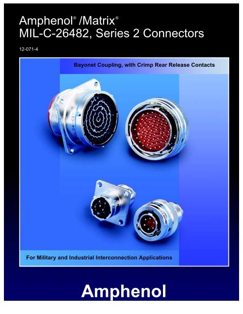
® ®<strong>Amphenol</strong> /Matrix<strong>MIL</strong>-C-<strong>26482</strong>, <strong>Series</strong> 2 Connectors12-071-4Bayonet Coupling, with Crimp Rear Release ContactsFor Military and Industrial Interconnection Applications<strong>Amphenol</strong>
This catalog covers the <strong>Amphenol</strong> ® /Matrix ® <strong>MIL</strong>-C-<strong>26482</strong>, <strong>Series</strong> 2 Connectors. These connectors arebayonet coupling type, and they feature crimp contactsthat are rear insertable and rear releasable. Theycan be ordered through <strong>Amphenol</strong>, by military orequivalent proprietary part numbers.The Matrix ® connectors covered in this catalogbroaden the miniature cylindrical family offered by<strong>Amphenol</strong>, so that now users have the broadest rangeof product available to them. Additional miniaturecylindricals are covered in the <strong>Amphenol</strong> catalog, 12-070, which is available upon request. The 12-070<strong>Amphenol</strong> ® catalog covers a large variety of miniaturecylindricals including the following:• <strong>MIL</strong>-C-<strong>26482</strong>, <strong>Series</strong> 1 - bayonet coupling connectorswith solder contacts• <strong>MIL</strong>-C-<strong>26482</strong>, <strong>Series</strong> 1 - bayonet coupling connectorswith front release crimp contacts• Other proprietary crimp and solder types includinghermetics and connectors with printed circuit boardcontacts, as well as other shell styles, alternativeconnector finishes and additional contact options• Additional miniature cylindricals that have doublestub threaded coupling rather than bayonet couplingSee page 15 for more information on these additionalminiature cylindrical connector products.Also, ask for these <strong>Amphenol</strong> Product Catalogs:<strong>Amphenol</strong> Industrial Connector Brochure, SL-381,for an overview of the industrial family of connectors.<strong>Amphenol</strong> Brochure SL-100, which provides anoverview of all products, military and industrial,offered through <strong>Amphenol</strong> <strong>Aerospace</strong>.Should more information be required concerning theconnectors covered in this publication, or if specialapplication needs arise, please contact:<strong>Amphenol</strong> Corporation<strong>Amphenol</strong> <strong>Aerospace</strong>40-60 Delaware AvenueSidney, New York 13838-1395Telephone 607-563-5011Fax: 607-563-5157Web site: www.<strong>Amphenol</strong>-<strong>Aerospace</strong>.comVisit our website for this catalog and other catalogs of<strong>Amphenol</strong> products.TABLE OF CONTENTS<strong>Amphenol</strong> ® /Matrix ® <strong>MIL</strong>-C-<strong>26482</strong>, <strong>Series</strong> 2ConnectorsIntroduction, Table of Contents. . . . . . . . . . . . . . . . . .1General Description, Features and Benefits. . . . . . . .2Class Descriptions, Performance Specifications . . . .3Shell Styles, Dimensional Data:Wall Mounting Receptacle, Narrow Flange . . . . . .4Wall Mounting Receptacle, Wide Flange . . . . . . . .5Cable Connecting Receptacle,. . . . . . . . . . . . . . . .6Jam Nut Receptacle. . . . . . . . . . . . . . . . . . . . . . . .7Straight Plug,Straight Plug with RFI Grounding Fingers . . . . . . .8Insert Arrangement Chart,Insert Alternate Positions . . . . . . . . . . . . . . . . . . . . . .9Insert Arrangement Patterns. . . . . . . . . . . . . . . . 10-12Contact Information, Sealing Plugs,Crimping and Insertion/Removal Tools. . . . . . . . . . .13How to Order . . . . . . . . . . . . . . . . . . . . . . . . . . . . . .14Additional <strong>MIL</strong>-C-<strong>26482</strong>/Miniature CylindricalConnectors offered by <strong>Amphenol</strong> . . . . . . . . . . . . . . .15Sales Office Listing<strong>Amphenol</strong> <strong>Aerospace</strong> operates Quality Systems that are Certifiedto ISO-9001 and AS-9100 by third party Registrars.1
® ®<strong>Amphenol</strong> /Matrix Miniature Cylindrical<strong>MIL</strong>-C-<strong>26482</strong>, <strong>Series</strong> 2 Connectors<strong>Amphenol</strong> broadens their Miniature Cylindrical Family ofConnectors with the addition of the Matrix ® Product lineof <strong>MIL</strong>-C-<strong>26482</strong>, <strong>Series</strong> 2 connectors.MS3470wall mounting receptaclewith narrow flangeMS3472wall mounting receptaclewith wide flangeMS3471cable connecting receptacleMS3474jam nut receptacleMS3476straight plugMS3475plug with RFI groundingfingersThis series provides a bayonet coupling connector with crimprear insertable, rear releasable contacts.DESIGN CHARACTERISTICS• Medium size, environmentally resistant connector• Recommended operating voltage to 1,000 VAC (RMS)at sea level• Quick positive coupling assured by 3 point bayonetcoupling system• Visual confirmation of complete coupling• Eliminates mismating by the use of five key/keyway design• Insertion and removal of contacts from the rear of the connectorassures no damage to the front that might affect thesealing characteristics• Utilizes same standard qualified rear-release type plastictool for contact insertion and removal• Contacts are qualified to <strong>MIL</strong>-C-39029 requirements – BINcoded (three color bands), and are crimped with standardcrimp tools per <strong>MIL</strong>-C-22520• Grommets are constructed of tear-resistant elastomer andexperience no degradation when exposed to a broadrange of fluids• Sealing over a range of wire diameters is assured by a triplewebbed grommet at the rear of the connector• Closed entry socket side of the insert is designed with alead-in chamfer and a hard face that will accept a pin contactbent within pre-established limits• Elastomer interfacial seal on the pin side has raised barriersaround each pin which displace into the socket chamferwhen mated, providing a positive moisture sealCUSTOMER OPTIONS• Shell styles within this family include:Wall mount with either a narrow or a wide flange, jam nutsingle hole mount, and cable connecting receptacles,along with standard plugs or plugs with RFI grounding fingers,in shell sizes 8 to 24• MS and Proprietary versions available• Accommodation of contact sizes 20, 16 and 12• 34 insert arrangement patterns available, accommodatingfrom a minimum of 3 to a maximum of 55 circuits• Alternate positioning available• Various finishes are available (for information on non-cadmiumzinc alloy plating, consult <strong>Amphenol</strong>, Sidney, NY)2
® ®<strong>Amphenol</strong> /Matrix Miniature Cylindrical<strong>MIL</strong>-C-<strong>26482</strong>, <strong>Series</strong> 2 Connectorsclass descriptions, performance specificationsCLASS DESCRIPTIONSMilitary<strong>MIL</strong>-C-<strong>26482</strong>, <strong>Series</strong> 2* Ref. <strong>MIL</strong>-C-<strong>26482</strong><strong>Amphenol</strong>/MatrixProprietary MB1 <strong>Series</strong>DescriptionClass L Class R Aluminum shell, electroless nickel finish, fluid resistantClass E – Inactive, superceded by Class L*Class R – Inactive, superceded by Class L*Class A Class A Aluminum shell, black non-conductive anodized finish, fluidresistant– Class G Stainless steel shell, passivated, fluid resistantClass W Class W Aluminum shell, olive drab cadmium plated, corrosion/fluidresistantPERFORMANCE SPECIFICATIONSServiceRatingRecommendedOperating AC Voltageat Sea LevelSERVICE RATINGS**Test Voltage AC (RMS), 60 cpsSea Level 50,000 ft. 70,000 ft. 110,000 ft.I 600 1,500 500 375 200II 1,000 2,300 750 500 200** Service Rating is comparable to MS rating A. Miniature connectors rated Service Rating I will provide a minimum flashovervoltage at sea level of 2,000 volts AC (RMS). Service Rating II is comparable to MS Service Rating D, and will provide aminimum flashover voltage of 2,800 volts AC (RMS) at sea level.Please note that the electrical data given is not an establishment of electrical safety factors. This is left entirely in thedesigner’s hands, as he can best determine which peak voltage, switching surges, transients, etc. can be expected in aparticular circuit.OPERATING TEMPERATURE RANGE–65°C (–85°F) to 200°C (392°F)ENVIRONMENTAL SEALWired, mated connectors with the specified accessoryattached will meet the altitude immersion test specified in<strong>MIL</strong>-C-<strong>26482</strong>.DURABILITYMinimum of 500 mating cycles.SHOCK AND VIBRATION REQUIREMENTSWhen tested as follows, the connector shall sustain nophysical damage, or electrical discontinuity exceedingone microsecond.SHOCK:Pulse of an approximate half sine wave of 300g magnitudewith duration of 3 milliseconds applied in three axes.VIBRATION:Sixteen hours of random vibration having a range of 50 to2,000 Hz with a 41.7G peak level.3
Miniature Cylindrical <strong>MIL</strong>-C-<strong>26482</strong>, <strong>Series</strong> 2MS3470wall mounting receptacle with narrow flangeReceptacle Shell, Wall Mount with Narrow Flange,Bayonet CouplingMilitary No. MS3470<strong>Amphenol</strong>/Matrix No. MB10Master KeywayA Max. Typ.B Typ.1.405 Max.Shell 8 Thru 181.465 Max.Shell 20, 22, & 24H Accessory Thread3 Teeth Equally Spaced120 Apart˚C Dia.D Dia. Max.GrommetT Dia. MountingHoles Typ. 4-PlacesBlue Color BandsEF.190Grommet Extension.130.290 Min. Full ThreadTo complete order number see how to order, page 14.ShellSizeAMax.B±.005C Dia.±.003D Dia.Max.EF±.016HAccessory ThreadClass 2A8 .828 .594 .471 .305 .462/.431 .062 .5000-20 UNF .12010 .954 .719 .588 .405 .462/.431 .062 .6250-24 UNEF .12012 1.047 .812 .748 .531 .462/.431 .062 .7500-20 UNEF .12014 1.141 .906 .873 .665 .462/.431 .062 .8750-20 UNEF .12016 1.234 .969 .998 .790 .462/.431 .062 1.0000-20 UNEF .12018 1.328 1.062 1.123 .869 .462/.431 .062 1.0625-18 UNEF .12020 1.453 1.156 1.248 .994 .587/.556 .094 1.1875-18 UNEF .12022 1.578 1.250 1.373 1.119 .587/.556 .094 1.3125-18 UNEF .12024 1.703 1.375 1.498 1.244 .620/.589 .094 1.4375-18 UNEF .147T±.0054
Miniature Cylindrical <strong>MIL</strong>-C-<strong>26482</strong>, <strong>Series</strong> 2MS3472wall mounting receptacle with wide flangeReceptacle Shell, Wall Mount with Wide Flange,Bayonet CouplingMilitary No. MS3472<strong>Amphenol</strong>/Matrix No. MB11Master KeywayA Max. Typ.B Typ.1.405 Max.Shell 8 Thru 181.465 Max.Shell 20, 22, & 24H Accessory Thread3 Teeth Equally Spaced120 Apart˚C Dia.D Dia. Max.Grommet.150 Dia. MountingHoles Typ. 4-PlacesBlue ColorBandsEF.190Grommet Extension.130.290 Min. Full ThreadTo complete order number see how to order, page 14.ShellSizeAMax.B±.005C Dia.±.003D Dia.Max.EF±.016H ThreadClass 2A8 1.065 .734 .471 .305 .493/.462 .062 .5000-20 UNF10 1.141 .812 .588 .405 .493/.462 .062 .6250-24 UNEF12 1.266 .938 .748 .531 .493/.462 .062 .7500-20 UNEF14 1.360 1.031 .873 .665 .493/.462 .062 .8750-20 UNEF16 1.453 1.125 .998 .790 .493/.462 .062 1.0000-20 UNEF18 1.532 1.203 1.123 .869 .493/.462 .062 1.0625-18 UNEF20 1.688 1.297 1.248 .994 .587/.556 .094 1.1875-18 UNEF22 1.766 1.375 1.373 1.119 .587/.556 .094 1.3125-18 UNEF24 1.891 1.500 1.498 1.244 .620/.589 .094 1.4375-18 UNEF5
Miniature Cylindrical <strong>MIL</strong>-C-<strong>26482</strong>, <strong>Series</strong> 2MS3471cable connecting receptacleReceptacle Shell, Cable Connecting,Bayonet CouplingMilitary No. MS3471<strong>Amphenol</strong>/Matrix No. MB13A Max. Typ.MasterKeywayE1.405 Max.Shell 8 Thru 181.465 Max.Shell 20, 22, &24F.290 Min.Full Thread3 Teeth EquallySpaced 120 Apart ˚CDia.D Dia. MaxGrommetB Dia.Blue ColorBandsH Accessory Thread.190Grommet Extension.130To complete order number see how to order, page 14.ShellSizeAMax.B Dia.±.020C Dia.±.003D Dia.Max.EF±.016H ThreadClass 2A8 .828 .938 .471 .305 .462/.431 .062 .5000-20 UNF10 .954 1.062 .588 .405 .462/.431 .062 .6250-24 UNEF12 1.047 1.156 .748 .531 .462/.431 .062 .7500-20 UNEF14 1.141 1.250 .873 .665 .462/.431 .062 .8750-20 UNEF16 1.234 1.344 .998 .790 .462/.431 .062 1.0000-20 UNEF18 1.328 1.438 1.123 .869 .462/.431 .062 1.0625-18 UNEF20 1.453 1.562 1.248 .994 .587/.556 .094 1.1875-18 UNEF22 1.578 1.688 1.373 1.119 .587/.556 .094 1.3125-18 UNEF24 1.703 1.812 1.498 1.244 .620/.589 .094 1.4375-18 UNEF6
Miniature Cylindrical <strong>MIL</strong>-C-<strong>26482</strong>, <strong>Series</strong> 2MS3474jam nut receptacleReceptacle Shell, Jam Nut Mount,Bayonet CouplingMilitary No. MS3474<strong>Amphenol</strong>/Matrix No. MB14A Max. Typ.Master Keyway1.405 MaxShell 8 Thru 181.465 Max.Shell 20, 22, & 24EFH AccessoryThread3 Teeth EquallySpaced 120 Apart˚BCDia.D Dia. Max.GrommetK Max.Typ.Blue Color BandJ Mounting ThreadLockwire Hole 3-PlacesEqually SpacedBlue Color Band.190Grommet Extension.130.290 Min. Full ThreadTo complete order number see how to order, page 14.ShellSizeAMax.B±.005C Dia.±.003D Dia.Max. E FHAccessory ThreadClass 2AJMounting ThreadClass 2A8 .954 .525 .471 .305 .707/.658 .113/.086 .5000-20 UNF .5625-24 UNEF .76710 1.078 .650 .588 .405 .707/.658 .113/.086 .6250-24 UNF .6875-24 UNEF .89212 1.266 .813 .748 .531 .707/.658 .113/.086 .7500-20 UNEF .8750-20 UNEF 1.07914 1.391 .937 .873 .665 .707/.658 .113/.086 .8750-20 UNEF 1.0000-20 UNEF 1.20516 1.516 1.061 .998 .790 .707/.658 .113/.086 1.0000-20 UNEF 1.1250-18 UNEF 1.32918 1.641 1.186 1.123 .869 .707/.658 .113/.086 1.0625-18 UNEF 1.2500-18 UNEF 1.45520 1.828 1.311 1.248 .994 .772/.721 .148/.096 1.1875-18 UNEF 1.3750-18 UNEF 1.57922 1.954 1.436 1.373 1.119 .772/.721 .148/.096 1.3125-18 UNEF 1.5000-18 UNEF 1.70524 2.078 1.561 1.498 1.244 .772/.721 .148/.096 1.4375-18 UNEF 1.6250-18 UNEF 1.829KMax.7
Miniature Cylindrical <strong>MIL</strong>-C-<strong>26482</strong>, <strong>Series</strong> 2MS3476 straight plugMS3475 straight plug with RFI grounding fingersA Dia.Max.OverKnurlMasterKeyway.290 Min. Full ThreadH Accessory Thread3 Teeth EquallySpaced 120 ˚ApartB Dia. MaxGrommet.190Grommet Extension.130Plug Shell,Bayonet CouplingMilitary No. MS3476<strong>Amphenol</strong>/Matrix No. MB16Blue ColorBandFully Coupled Indicators.320 Min.1.420 Max.Master Keyway.290 Min. Full ThreadA Dia.Max.OverKnurlRFIFingersH Accessory Thread3 Teeth EquallySpaced 120 ApartB Dia. MaxGrommet˚Plug Shell, RFI Grounding,Bayonet CouplingMilitary No. MS3475<strong>Amphenol</strong>/Matrix No. MB18BlueColor Band.190Grommet Extension.130Fully Coupled Indicators.320 Min.1.420 Max.To complete order number see how to order, page 14.ShellSizeA Dia.Max.B Dia.Max.HAccessory ThreadClass 2A8 .782 .305 .5000-20 UNF10 .926 .405 .6250-24 UNEF12 1.043 .531 .7500-20 UNEF14 1.183 .665 .8750-20 UNEF16 1.305 .790 1.0000-20 UNEF18 1.391 .869 1.0625-18 UNEF20 1.531 .994 1.1875-18 UNEF22 1.656 1.119 1.3125-18 UNEF24 1.777 1.244 1.4375-18 UNEF8
Miniature Cylindrical <strong>MIL</strong>-C-<strong>26482</strong>, <strong>Series</strong> 2insert arrangements, insert alternate positioningINSERT ARRANGEMENTSInsert Service TotalContact SizeArrangement Rating Contacts 12 16 208-33 I 3 38-98 I 3 310-6 I 6 612-3 II 3 312-8 I 8 812-10 I 10 1014-4 I 4 414-5 II 5 514-9S I 9 4 514-12 I 12 4 814-15 I 15 1 1414-18 I 18 1814-19 I 19 1916-8 II 8 816-23S I 23 1 2216-26 I 26 2618-8 I 8 818-11S II 11 1118-30S I 30 1 2918-32 I 32 3220-16 II 16 1620-24S I 24 2420-39 I 39 2 3720-41 I 41 4122-12S I 12 1222-19S I 19 1922-21 II 21 2122-32S I 32 3222-41 I 41 14 2722-55 I 55 5522-95S I 32 6 2624-19S II 19 1924-31 I 31 3124-61 I 61 61Arrangements designated with an S are tooled in socket only.INSERT ALTERNATE POSITIONINGTo avoid cross-plugging problems in applications requiring the useof more than one connector of the same size and arrangement,alternate rotations are available as indicated in the chart below.As shown in the diagram, the front face of the pin insert is rotatedwithin the shell in a clockwise direction from the normal shell key.The socket insert would be rotated counter-clockwise the samenumber of degrees in respect to the normal shell key.9A BA BPosition W Position X Position Y Position ZView looking into front face of pin insert or rear of socket insert.InsertDegreesArrangement W X Y Z8-33 90 – – –8-98 – – – –10-6 90 – – –12-3 – – 180 –12-8 90 112 203 29212-10 60 155 270 29514-4 45 – – –14-5 40 92 184 27314-9 15 90 180 27014-12 43 90 – –14-15 17 110 155 23414-18 15 90 180 27014-19 30 165 315 –16-8 54 152 180 33116-23 158 270 – –16-26 60 – 275 33818-8 180 – – –18-11 62 119 241 34018-30 180 193 285 35018-32 85 138 222 26520-16 238 318 333 34720-24 70 145 215 29020-39 63 144 252 33320-41 45 126 225 –22-12 – – – –22-19 15 90 225 30822-21 16 135 175 34922-32 72 145 215 28822-41 39 135 264 –22-55 30 142 226 31422-95 26 180 266 –24-19 30 165 315 –24-31 90 225 255 –24-61 90 180 270 324A BA B
Miniature Cylindrical <strong>MIL</strong>-C-<strong>26482</strong>, <strong>Series</strong> 2contact arrangementsfront face of pin insert or rear face of socket insert illustratedCBACBAFEDACBCBAGFEABHCDGH A BK JF E DCInsert Arrangement 8-33 8-98 10-06 12-03 12-08 12-10Service Rating I I I II I INumber of Contacts 3 3 6 3 8 10Contact Size 20 20 20 16 20 20DCABEDACBHGFJAEBDCGMFHEAJ BKL CDKJRHGL AMPFBNCDEInsert Arrangement 14-04 14-05 14-09 14-12 14-15Service Rating I II I I INumber of Contacts 4 5 5 4 8 4 14 1Contact Size 12 16 20 12 20 16 20 16L AK M N BJ T U P CHS RDG F EM ABL N PCK U VRDJ T SEHG FFGEAHDBCNMYLXKWJHP AR BSZ CTDUEVFGPNaRSMZLYKJABTCUbDc VEXW FGHInsert Arrangement 14-18 14-19 16-08 16-23 16-26Service Rating I I II I INumber of Contacts 18 19 8 22 1 26Contact Size 20 20 16 20 16 20CONTACT LEGEND 20 16 1210
Miniature Cylindrical <strong>MIL</strong>-C-<strong>26482</strong>, <strong>Series</strong> 2contact arrangementsfront face of pin insert or rear face of socket insert illustratedFGEAHDBCGHFJAKLDEBCSR dP cN bMagLZKJABT CeU DVEfWFYXGHST AR U BeVPCdfWNjgDcXMEhbYFLa ZHKJ GInsert Arrangement 18-08 18-11 18-30 18-32Service Rating I II I INumber of Contacts 8 11 29 1 32Contact Size 12 16 20 16 20VW AA BLAL M AUXBWCXjVKYjMBWNTCY DKXBikZU i kZ ES NSDs mh rmYJCVaaT htaPFEJCRSrnR PgbqFHZp ngGbURPR q pHDDfcfHT SNGce dP e d JGEGEMHNKFFL K JM LInsert Arrangement 20-16 20-24 20-39 20-41Service Rating II I I INumber of Contacts 16 24 37 2 41Contact Size 16 20 20 16 20HGJMFALKEBDCJKHLUTGMNVSFAPREBDCNMWLVKJUHPXGABRCSDTEFInsert Arrangement 22-12 22-19 22-21Service Rating I I IINumber of Contacts 12 19 21Contact Size 12 12 16CONTACT LEGEND 20 16 1211
Miniature Cylindrical <strong>MIL</strong>-C-<strong>26482</strong>, <strong>Series</strong> 2contact arrangementsfront face of pin insert or rear face of socket insert illustratedN APbRMBa h c SLCZ g j d TKDf eYUJEXVWHFGXWjVAYZBCkamDbsnEU itcrpFT h q d GgSeHfRJPN M L KU ATBSVnCWmpk AAXq YRBBDzGG CCrZP jHH s Ey FF DD aN iEE t Fxu bh w v cM gd GLf eHKJInsert Arrangement 22-32 22-41 22-55Service Rating I I INumber of Contacts 32 27 14 55Contact Size 20 20 16 20UTSRAXWYV hgjfBCDZEaFbGe d cHPJNMKLKLJMNUTA BPV RSH G FCEDKJLYXWHMZfeVGNagdUAPbcTFBQRSECDInsert Arrangement 22-95 24-19 24-31Service Rating I II INumber of Contacts 26 6 19 31Contact Size 20 12 12 16AZa b BYc Cu vXdtDHH weW GGxs NN JJEfV FF PP y Fr MM KKgU EE LL zqGhDDAATpHCC BB iS nj Jm kR KPN L MInsert Arrangement 24-61Service RatingINumber of Contacts 61Contact Size 20CONTACT LEGEND 20 16 1212
Miniature Cylindrical <strong>MIL</strong>-C-<strong>26482</strong>, <strong>Series</strong> 2contact information, sealing plugs,crimping and insertion/removal tools<strong>MIL</strong>-C-<strong>26482</strong>, SERIES 2CRIMP CONTACTSContactSizeWire Range Socket Contacts Pin ContactsAWG mm 2 Part NumberMilitary<strong>Amphenol</strong>/MatrixPart NumberMilitaryPart Number<strong>Amphenol</strong>/MatrixPart Number20 24-20 0.2-0.6 M39029/5-115 M5100-001-0020L M39029/4-110 M5000-054-0020L16 20-16 0.5-1.4 M39029/5-116 M5100-001-0016L M39029/4-111 M5000-054-0016L12 14-12 2-3 M39029/5-118 M5100-001-0012L M39029/4-113 M5000-054-0012LCONTACT CURRENT RATING AND RETENTIONContact DC TestContact RetentionAxial LoadSize* Amperage lb.N20 7.5 15 66.716 13.0 25 111.212 23.0 30 133.4* Organize individual circuits to maintain heat rise withinoperating temperature requirements.SEALING PLUGSContactSizeMilitaryPart NumberSealing Plugs<strong>Amphenol</strong>/MatrixPart Number20 MS27488-20 10-405996-02016 MS27488-16 10-405996-01612 MS27488-12 10-405996-012CRIMPING TOOLSContactSizeWire RangeFinished Wire Dia. RangeAWG mm 2 Inch mm20 24-20 0.2-0.6 .040-.083 1.02-2.11Crimping ToolPart NumberM22520/1-01 orM22520/2-01Turret or PositionerPart NumberM22520/1-02 orM22520/2-0216 20-16 0.5-1.4 .053-.103 1.34-2.62 M22520/1-01 M22520/1-0212 14-12 2-3 .097-.158 2.46-4.01 M22520/1-01 M22520/1-02INSERTION/REMOVAL TOOLSContactSizeColor CodeMilitaryPart Number<strong>Amphenol</strong>/MatrixPart Number20 Red/White M81969/14-11 10-538988-02116 Blue/White M81969/14-03 10-538988-01612 Yellow/White M81969/14-04 10-538988-012Note: Each connector is furnished with contacts. One spare for inserts requiring1 to 26 of each contact, two spares for inserts with more than 26contacts, and a minimum of one sealing plug up to 15% of the numberof contacts.13
<strong>MIL</strong>-C-<strong>26482</strong>, <strong>Series</strong> 2how to orderHOW TO ORDER BY <strong>MIL</strong>ITARY PART NUMBER<strong>MIL</strong>-C-<strong>26482</strong> SERIES 2 CONNECTORSMS 3470 W 12 10 P W1 2 3 4 5 6 71. Connector TypeMS designates Military Standard2. Connector Style3470 wall mounting receptacle with narrow flange3472 wall mounting receptacle with wide flange3471 cable connecting receptacle3474 jam nut receptacle3476 straight plug3475 straight plug with RFI grounding fingers3. Service ClassL aluminum shell, electroless nickel finish, fluidresistant insertA aluminum shell, black anodized finish, non-conductivefluid resistant insertW aluminum shell, olive drab cadmium plated, fluidresistant insertNote: For stainless steel shell, passivated, order by <strong>Amphenol</strong> ® /Matrix ®proprietary Class G.Class L inactivates older classes E and R (Ref. <strong>MIL</strong>-C-<strong>26482</strong>)4., 5. Shell size and insert arrangement - See chart on page 9and pattern drawings that follow.6. Contact TypesP designates pinS designates socketA designates less pinsB designates less socketsNote:Use A & B only when other than a full complement of power contactsis to be installed.7. Insert Rotation“W”, “X”, “Y”, “Z” designate that insert is rotated in its shellfrom normal position. No letter required for normal (norotation) position. See page 9 for description of alternatepositions.HOW TO ORDER BY PROPRIETARY PART NUMBER<strong>MIL</strong>-C-<strong>26482</strong> SERIES 2 CONNECTORSMB1 0 W 12 10 P W ***1 2 3 4 5 6 7 81. Connector TypeMB1 designates <strong>Amphenol</strong> ® /Matrix ® Bayonet CouplingConnector2. Connector Style0 wall mounting receptacle with narrow flange1 wall mounting receptacle with wide flange3 cable connecting receptacle4 jam nut receptacle6 straight plug8 straight plug with RFI grounding fingers3. Service ClassA aluminum shell, black anodize finish, non-conductive,fluid resistant insertR aluminum shell, electroless nickel finish, fluidresistant insertG stainless steel shell, passivated, fluid resistantinsertW aluminum shell, cadmium plated, olive drab finish,fluid resistant insert4., 5. Shell size and insert arrangement - See chart on page 9and pattern drawings that follow.6. Contact TypesP designates pinS designates socket7. Insert Rotation“W”, “X”, “Y”, “Z” designate that insert is rotated in its shellfrom normal position. No letter required for normal (norotation) position. See page 9 for description of alternatepositions.8. Modification NumberConsult <strong>Amphenol</strong>, Sidney, NY for information.For strain reliefs use the following modification codes:(189) E-nut M85049/31 configuration(190) Straight strain relief M85049/52 configuration(191) 90° strain relief M85049/51 configurationFor ordering information on accessories, such as protectioncaps and backshell hardware, contact <strong>Amphenol</strong>, Sidney, NY.14
Additional Miniature Cylindrical Connectorsoffered by <strong>Amphenol</strong>Miniature CylindricalProprietary/<strong>MIL</strong>-C-<strong>26482</strong>, <strong>Series</strong> 1 & 2ConnectorsThere are several additional connector series withinthe <strong>Amphenol</strong> ® <strong>MIL</strong>-C-<strong>26482</strong> and similar types family.Each series offers varying design characteristicsand customer options to meet costconsiderations and to provide users with the mostdesign flexibility possible.The additional series within the <strong>Amphenol</strong> Miniature CylindricalFamily of Connectors are shown in detail in <strong>Amphenol</strong> catalog12-070, which can be supplied upon request. Briefly these additionalproducts are described as follows:• PT, SP, MS/PTProprietary/<strong>MIL</strong>-C-<strong>26482</strong>, <strong>Series</strong> 1These are bayonet type with solder contacts. Both the insertand main joint gasket are molded from resilient neoprene.This provides excellent moisture sealing at the gasket andsuperior electrical isolation of the contact in the inserts.Socket contacts are closed entry design. Printed circuitboard contacts are also available in this series.The SP is a modification of the PT providing special shellswith a wide mounting flange for back panel mounting. TheSP also has a durable non-conductive hard anodic “Alumilite”coating which provides abrasion and corrosion protection.There are 8 shell styles in the PT, SP and MS/PT series, andshell sizes are 6-24. The PT solder is UL recognized. Hermeticsare also available.• PT-SE, SP-SE, MS/PT-SEProprietary/<strong>MIL</strong>-C-<strong>26482</strong>, <strong>Series</strong> 1These are a derivative of the PT line, bayonet type. However,they incorporate crimp contacts that are rear insertable,front releasable. An MS approved spring towerretention system holds the contacts in place.• PT-CE, SP-CEProprietary crimp typeAnother derivative of the PT line, bayonet type. These alsohave crimp contacts that are rear insertable, front releasable,but the contacts are held in place by a nylon waferretention system. The voidless one-piece insert and grommetassembly provide continuous dielectric separationbetween contacts.• PC, PC-SE, PC-CEProprietary solder and crimp typeThe PC series within the <strong>Amphenol</strong> ® miniature cylindricalfamily is threaded coupling, rather than bayonet coupling.The threads are double-stubbed so they can not be crossthreaded.The PC is offered with solder contacts. The PC-SE hascrimp contacts in a spring tower retention system, while thePC-CE has crimp contacts in a nylon wafer retention system.Hermetics are availableAll miniature cylindricals are intermateable and intermountablewith each other except for the threaded coupling PC <strong>Series</strong>.For further information ask for catalog 12-070. Consult <strong>Amphenol</strong>,Sidney, NY for any assistance on these products or for anyspecific application needs.15


