<strong>SH564128FH8N0QHSCR</strong>April 11, 2011Device Timing Parameters Notes1. Actual value dependant upon measurement level definitions which are TBD.2. Commands requiring a locked DLL are: READ (and RAP) and synchronous ODT commands.3. The max values are system dependent.4. WR as programmed in the Mode Register.5. Value must be rounded-up to next higher integer value.6. There is no maximum cycle time limit besides the need to satisfy the refresh interval, t REFI .7. Minimum RTT turn-on time (t AON min) is the point in time when the device leaves high impedance and ODT resistance begins to turn on.Maximum RTT turn on time (t AON max) is the point in time when the ODT resistance is fully on. Both are measured from ODTLon.8. Minimum RTT turn-off time (t AOF min) is the point in time when the device starts to turn off the ODT resistance. Maximum RTT turn off time(t AOF max) is the point in time when the on-die termination has reached high impedance. Both are measured from ODTLoff.9. t WR is defined in ns, for calculation of t WRPDEN it is necessary to round up t WR /t CK to the next integer.10. WR is in clock cycles as programmed in MR0.11. The maximum postamble is bound by t HZDQS (max).12. Output timing deratings are relative to the SDRAM input clock. When the device is operated with input clock jitter, this parameter needs tobe derated by TBD.13. Value is only valid for RON34.14. Single ended signal parameter.15. t REFI depends on T OPER .16. t IS(base) and t IH(base) values are for 1V/ns CMD/ADD single-ended slew rate and 2V/ns CK, CK differential slew rate. Note for DQ and DMsignals, V REF(DC) = V REFDQ(DC) . For input only pins except RESET, V REF(DC) = V REFCA(DC) .17. t DS(base) and t DH(base) values are for 1V/ns DQ single-ended slew rate and 2V/ns DQS, DQS differential slew rate. Note for DQ and DMsignals, V REF(DC) = V REFDQ(DC) . For input only pins except RESET, V REF(DC) = V REFCA(DC) .18. Start of internal write transaction is defined as follows:For BL8 (fixed by MRS and on- the-fly): Rising clock edge 4 clock cycles after WL.For BC4 (on- the- fly): Rising clock edge 4 clock cycles after WL.For BC4 (fixed by MRS): Rising clock edge 2 clock cycles after WL.19. The maximum preamble is bound by t LZDQS (min).20. CKE is allowed to be registered low while operations such as row activation, precharge, autoprecharge or refresh are in progress, butpower-down IDD spec will not be applied until finishing those operations.21. Although CKE is allowed to be registered LOW after a REFRESH command once t REFPDEN (min) is satisfied, there are cases where additionaltime such as t XPDLL (min) is also required.22. Defined between end of MPR read burst and MRS which reloads MPR or disables MPR function.23. One ZQCS command can effectively correct a minimum of 0.5% (ZQCorrection) of RON and RTT impedance error within 64 nCK for allspeed bins assuming the maximum sensitivities specified in the ‘Output Driver Voltage and Temperature Sensitivity’ and ‘ODT Voltage andTemperature Sensitivity’ tables. The appropriate interval between ZQCS commands can be determined from these tables and other application-specificparameters.One method for calculating the interval between ZQCS commands, given the temperature (Tdriftrate) and voltage (Vdriftrate) drift ratesthat the SDRAM is subject to in the application, is illustrated. The interval could be defined by the following formula:ZQCorrection------------------------------------------------------------------------------------------------------------------------( TSens × Tdriftrate) + ( VSens × Vdriftrate)where TSens = max(dRTTdT, dRONdTM) and VSens = max(dRTTdV, dRONdVM) define the SDRAM temperature and voltage sensitivities.For example, if TSens = 1.5% / °C, VSens = 0.15% / mV, Tdriftrate = 1 °C / sec and Vdriftrate = 15 mV / sec, then the interval betweenZQCS commands is calculated as:0.5( ---------------------------------------------------------- =1.5 × 1) + ( 0.15 + 15)0.133 ≈ 128ms24. n = from 13 cycles to 50 cycles. This row defines 38 parameters.25. t CH(abs) is the absolute instantaneous clock high pulse width, as measured from one rising edge to the following falling edge.26. t CL(abs) is the absolute instantaneous clock low pulse width, as measured from one falling edge to the following rising edge.27. The t IS(base) AC150 specifications are adjusted from the t IS(base) specification by adding an additional 100 ps of derating to accommodatefor the lower alternate threshold of 150 mV and another 25 ps to account for the earlier reference point [(175 mv - 150 mV) / 1 V/ns].28. Pulse width of a input signal is defined as the width between the first crossing of V REFDC and the consecutive crossing of V REFDC .Corporate Headquarters: P. O. Box 1757, Fremont, CA 94538, USA • Tel:(510) 623-1231 • Fax:(510) 623-1434 • E-mail: info@smartm.comEurope: 5 Kelvin Park South, Kelvin South, East Kilbride, G75 ORH, United Kingdom • Tel: +44-870-870-8747 • Fax: +44-870-870-8757Asia/Pacific: Plot 18, Lrg Jelawat 4, Kawasan Perindustrian Seberang Jaya 13700, Prai, Penang, Malaysia • Tel: +604-3992909 • Fax: +604-399290340
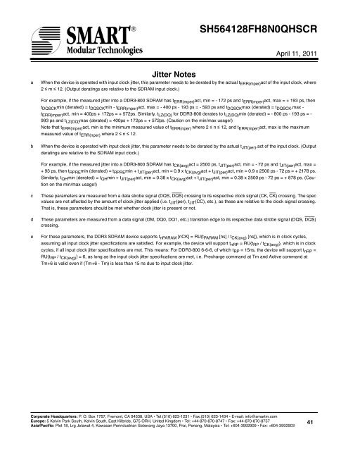
<strong>SH564128FH8N0QHSCR</strong>April 11, 2011aJitter NotesWhen the device is operated with input clock jitter, this parameter needs to be derated by the actual t ERR(mper) act of the input clock, where2 ≤ m ≤ 12. (Output deratings are relative to the SDRAM input clock.)For example, if the measured jitter into a DDR3-800 SDRAM has t ERR(mper) act, min = - 172 ps and t ERR(mper) act, max = + 193 ps, thent DQSCK min (derated) = t DQSCK min - t ERR(mper) act, max = - 400 ps - 193 ps = - 593 ps and t DQSCK max (derated) = t DQSCK ,max -t ERR(mper) act, min = 400ps + 172ps = + 572ps. Similarly, t LZ(DQ) for DDR3-800 derates to t LZ(DQ) min (derated) = - 800 ps - 193 ps = -993 ps and t LZ(DQ) max (derated) = 400ps + 172ps = + 572ps. (Caution on the min/max usage!)Note that t ERR(mper) act, min is the minimum measured value of t ERR(nper) where 2 ≤ n ≤ 12, and t ERR(mper) act, max is the maximummeasured value of t ERR(nper) where 2 ≤ n ≤ 12.bWhen the device is operated with input clock jitter, this parameter needs to be derated by the actual t JIT(per) ,act of the input clock. (Outputderatings are relative to the SDRAM input clock.)For example, if the measured jitter into a DDR3-800 SDRAM has t CK(avg) act = 2500 ps, t JIT(per) act, min = - 72 ps and t JIT(per) act, max =+ 93 ps, then t RPRE min (derated) = t RPRE min + t JIT(per) act, min = 0.9 x t CK(avg) act + t JIT(per) act, min = 0.9 x 2500 ps - 72 ps = + 2178 ps.Similarly, t QH min (derated) = t QH min + t JIT(per) act, min = 0.38 x t CK(avg) act + t JIT(per) act, min = 0.38 x 2500 ps - 72 ps = + 878 ps. (Cautionon the min/max usage!)cdeThese parameters are measured from a data strobe signal (DQS, DQS) crossing to its respective clock signal (CK, CK) crossing. The specvalues are not affected by the amount of clock jitter applied (i.e. t JIT (per), t JIT (CC), etc.), as these are relative to the clock signal crossing.That is, these parameters should be met whether clock jitter is present or not.These parameters are measured from a data signal (DM, DQ0, DQ1, etc.) transition edge to its respective data strobe signal (DQS, DQS)crossing.For these parameters, the DDR3 SDRAM device supports t nPARAM [nCK] = RU{t PARAM [ns] / t CK(avg) [ns]}, which is in clock cycles,assuming all input clock jitter specifications are satisfied. For example, the device will support t nRP = RU{t RP / t CK(avg) }, which is in clockcycles, if all input clock jitter specifications are met. This means: For DDR3-800 6-6-6, of which t RP = 15ns, the device will support t nRP =RU{t RP / t CK(avg) } = 6, as long as the input clock jitter specifications are met, i.e. Precharge command at Tm and Active command atTm+6 is valid even if (Tm+6 - Tm) is less than 15 ns due to input clock jitter.Corporate Headquarters: P. O. Box 1757, Fremont, CA 94538, USA • Tel:(510) 623-1231 • Fax:(510) 623-1434 • E-mail: info@smartm.comEurope: 5 Kelvin Park South, Kelvin South, East Kilbride, G75 ORH, United Kingdom • Tel: +44-870-870-8747 • Fax: +44-870-870-8757Asia/Pacific: Plot 18, Lrg Jelawat 4, Kawasan Perindustrian Seberang Jaya 13700, Prai, Penang, Malaysia • Tel: +604-3992909 • Fax: +604-399290341
- Page 1 and 2: SH564128FH8N0QHSCRApril 11, 2011Ord
- Page 3 and 4: SH564128FH8N0QHSCRApril 11, 20114GB
- Page 5 and 6: SH564128FH8N0QHSCRApril 11, 2011DDR
- Page 7 and 8: SH564128FH8N0QHSCRApril 11, 2011Blo
- Page 9 and 10: SH564128FH8N0QHSCRApril 11, 2011Ser
- Page 11 and 12: SH564128FH8N0QHSCRApril 11, 2011Ser
- Page 13 and 14: SH564128FH8N0QHSCRApril 11, 2011Mod
- Page 15 and 16: SH564128FH8N0QHSCRApril 11, 2011Mod
- Page 17 and 18: SH564128FH8N0QHSCRApril 11, 2011Com
- Page 19 and 20: SH564128FH8N0QHSCRApril 11, 2011Abs
- Page 21 and 22: SH564128FH8N0QHSCRApril 11, 2011Inp
- Page 23 and 24: SH564128FH8N0QHSCRApril 11, 2011Sym
- Page 25 and 26: SH564128FH8N0QHSCRApril 11, 2011IDD
- Page 27 and 28: SH564128FH8N0QHSCRApril 11, 2011IDD
- Page 29 and 30: SH564128FH8N0QHSCRApril 11, 2011IDD
- Page 31 and 32: SH564128FH8N0QHSCRApril 11, 2011IDD
- Page 33 and 34: SH564128FH8N0QHSCRApril 11, 2011Ref
- Page 35 and 36: SH564128FH8N0QHSCRApril 11, 2011Dev
- Page 37 and 38: SH564128FH8N0QHSCRApril 11, 2011Par
- Page 39: SH564128FH8N0QHSCRApril 11, 2011Par
- Page 43: SH564128FH8N0QHSCRApril 11, 2011Dis