Dual fuel gas oil/ gas burner - Riello Burners
Dual fuel gas oil/ gas burner - Riello Burners
Dual fuel gas oil/ gas burner - Riello Burners
- No tags were found...

Create successful ePaper yourself
Turn your PDF publications into a flip-book with our unique Google optimized e-Paper software.
Installation, use and maintenance instructionsGB<strong>Dual</strong> <strong>fuel</strong> <strong>gas</strong> <strong>oil</strong>/ <strong>gas</strong> <strong>burner</strong>Two-stage progressive or modulating operation <strong>gas</strong> side / two-stage <strong>gas</strong> <strong>oil</strong> sideCODE MODEL TYPE20033168 RLS 190/M MZ 784 T20033366 (2) - 04/2011
Contents1 Declaration.................................................................................................................................................................................. 32 Information and general warnings............................................................................................................................................ 42.1 Information about the instruction manual .................................................................................................................... 42.1.1 Introduction.................................................................................................................................................................. 42.1.2 General dangers.......................................................................................................................................................... 42.1.3 Danger: live components............................................................................................................................................. 42.2 Guarantee and responsibility....................................................................................................................................... 52.3 Guidance for the use of bio <strong>fuel</strong> blends up to 10%...................................................................................................... 52.3.1 Information and general instructions ........................................................................................................................... 62.3.2 Product Disclaimer Statement..................................................................................................................................... 63 Safety and prevention................................................................................................................................................................ 73.1 Introduction.................................................................................................................................................................. 73.2 Safety warnings........................................................................................................................................................... 73.3 Basic safety rules ........................................................................................................................................................ 73.4 Personnel training ....................................................................................................................................................... 74 Technical description of the <strong>burner</strong> ......................................................................................................................................... 84.1 Burner designation ...................................................................................................................................................... 84.2 Models available.......................................................................................................................................................... 84.3 Technical data ............................................................................................................................................................. 94.4 Countries of destination - Burner categories ............................................................................................................... 94.5 Packaging - Weight ................................................................................................................................................... 104.6 Overall dimensions.................................................................................................................................................... 104.7 Firing rate .................................................................................................................................................................. 114.8 Test b<strong>oil</strong>er.................................................................................................................................................................. 114.8.1 Modulation ratio......................................................................................................................................................... 114.8.2 Commercial b<strong>oil</strong>ers.................................................................................................................................................... 114.9 Burner description ..................................................................................................................................................... 124.10 Standard equipment .................................................................................................................................................. 125 Installation ................................................................................................................................................................................ 135.1 Notes on safety for the installation ............................................................................................................................ 135.2 Handling .................................................................................................................................................................... 135.3 Preliminary checks .................................................................................................................................................... 135.4 Installer/Servicer notes for the use of Gas <strong>oil</strong> with Bio blends up to 10% ................................................................. 145.5 Operating position ..................................................................................................................................................... 145.6 B<strong>oil</strong>er plate ................................................................................................................................................................ 145.7 Blast tube length........................................................................................................................................................ 155.8 Securing the <strong>burner</strong> to the b<strong>oil</strong>er ............................................................................................................................... 155.9 Nozzle installation ..................................................................................................................................................... 155.9.1 Choice of nozzles for 1st and 2nd stage ................................................................................................................... 155.9.2 Nozzle assembly ....................................................................................................................................................... 165.10 Servomotor................................................................................................................................................................ 175.11 Gas <strong>oil</strong> supply............................................................................................................................................................ 185.11.1 Double-pipe circuit..................................................................................................................................................... 185.11.2 The loop circuit .......................................................................................................................................................... 185.11.3 Single-pipe circuit ...................................................................................................................................................... 195.12 Hydraulic system layout ............................................................................................................................................ 195.13 Hydraulic connections ............................................................................................................................................... 205.14 Pump ......................................................................................................................................................................... 205.14.1 Technical data ........................................................................................................................................................... 205.14.2 Pump priming ............................................................................................................................................................ 205.15 Gas supply ................................................................................................................................................................ 225.15.1 Gas line ..................................................................................................................................................................... 225.15.2 Gas train.................................................................................................................................................................... 235.15.3 Gas pressure............................................................................................................................................................. 23200333661 GB
Contents6 Electrical system.......................................................................................................................................................................256.1 Notes on safety for the electrical wiring .....................................................................................................................256.2 Electrical connections ................................................................................................................................................256.2.1 Calibration of thermal cut-out.....................................................................................................................................266.3 Current to the UV photocell........................................................................................................................................267 Start-up, calibration and operation of the <strong>burner</strong> ..................................................................................................................277.1 Notes on safety for the first start-up...........................................................................................................................277.2 Adjustment before first firing (<strong>gas</strong> <strong>oil</strong> operation) ........................................................................................................277.2.1 Combustion head setting ...........................................................................................................................................277.2.2 Pump adjustment .......................................................................................................................................................277.2.3 Fan gate adjustment ..................................................................................................................................................277.3 Burner calibration (<strong>gas</strong> <strong>oil</strong> operation) .........................................................................................................................277.3.1 Firing ..........................................................................................................................................................................277.3.2 Operation ...................................................................................................................................................................287.4 Adjustment before first firing (<strong>gas</strong> operation) .............................................................................................................287.5 Burner starting (<strong>gas</strong> operation) ..................................................................................................................................297.6 Burner firing (<strong>gas</strong> operation) ......................................................................................................................................297.7 Burner calibration (<strong>gas</strong> operation)..............................................................................................................................297.7.1 Firing output ...............................................................................................................................................................297.7.2 MAX <strong>burner</strong> output.....................................................................................................................................................297.7.3 MIN <strong>burner</strong> output ......................................................................................................................................................307.7.4 Intermediate outputs ..................................................................................................................................................307.7.5 Air pressure switch.....................................................................................................................................................317.7.6 Maximum <strong>gas</strong> pressure switch...................................................................................................................................317.7.7 Minimum <strong>gas</strong> pressure switch....................................................................................................................................317.8 Combustion checks....................................................................................................................................................327.9 Burner operation ........................................................................................................................................................327.9.1 Burner flame goes out during operation.....................................................................................................................328 Maintenance ..............................................................................................................................................................................338.1 Notes on safety for the maintenance .........................................................................................................................338.2 Maintenance programme ...........................................................................................................................................338.2.1 Maintenance frequency..............................................................................................................................................338.2.2 Checking and cleaning...............................................................................................................................................338.3 Opening the <strong>burner</strong> ....................................................................................................................................................358.4 Closing the <strong>burner</strong>......................................................................................................................................................359 Faults - Possible causes - Solutions.......................................................................................................................................36AAppendix - Accessories (optional)..........................................................................................................................................40BAppendix - Electrical panel layout...........................................................................................................................................41200333662 GB
Declaration1 DeclarationDeclaration of conformity in accordance with ISO / IEC 17050-1Manufacturer:RIELLO S.p.A.Address: Via Pilade <strong>Riello</strong>, 737045 Legnago (VR)Product:<strong>Dual</strong> <strong>fuel</strong> <strong>gas</strong> <strong>oil</strong>/ <strong>gas</strong> <strong>burner</strong>Model:RLS 190/M MZThese products are in compliance with the following Technical Standards:EN 676EN 267EN 292and according to the European Directives:GAD 90/396/EEC Gas Devices DirectiveMD 2006/42/EC Machine DirectiveLVD 2006/95/EC Low Voltage DirectiveEMC 2004/108/EC Electromagnetic CompatibilitySuch products are marked as follows:CE-0085BP0439The quality is guaranteed by a quality and management system certified in accordance with UNI EN ISO 9001.Manufacturer's DeclarationRIELLO S.p.A. declares that the following products comply with the NOx emission limits specified by German standard“1. BImSchV release 26.01.2010”.Product Type Model Power<strong>Dual</strong> <strong>fuel</strong> <strong>gas</strong> <strong>oil</strong>/ <strong>gas</strong> <strong>burner</strong> 784 T RLS 190/M MX 550 - 2150 kWLegnago, 31.03.2010Mr. G. Conticini<strong>Burners</strong> Division DepartmentRIELLO S.p.A.200333663 GB
Information and general warnings2 Information and general warnings2.1 Information about the instruction manual2.1.1 IntroductionThe instruction manual supplied with the <strong>burner</strong>: is an integral and essential part of the product and must notbe separated from it; it must therefore be kept carefully forany necessary consultation and must accompany the <strong>burner</strong>even if it is transferred to another owner or user, or toanother system. If the manual is lost or damaged, anothercopy must be requested from the Technical AssistanceService of the area; is designed for use by qualified personnel; offers important indications and instructions relating to theinstallation safety, start-up, use and maintenance of the<strong>burner</strong>.Symbols used in the manualIn some parts of the manual you will see triangular DANGERsigns. Pay great attention to these, as they indicate a situation ofpotential danger.2.1.2 General dangersThe dangers can be of 3 levels, as indicated below.DANGERWARNINGCAUTIONMaximum danger level!This symbol indicates operations which, if not carriedout correctly, cause serious injury, death orlong-term health risks.This symbol indicates operations which, if not carriedout correctly, may cause serious injury, deathor long-term health risks.This symbol indicates operations which, if not carriedout correctly, may cause damage to the machineand/or injury to people.2.1.3 Danger: live componentsDANGEROther symbolsAbbreviations usedCh. ChapterFig. FigurePage PageSec. SectionTab. TableThis symbol indicates operations which, if not carriedout correctly, lead to electric shocks with lethalconsequences.ENVIRONMENTAL PROTECTIONThis symbol gives indications for the use of themachine with respect for the environment.This symbol indicates a list.Delivery of the system and the instruction manualWhen the system is delivered, it is important that: the instruction manual is delivered to the user by the systemmanufacturer, with the recommendation to keep it in theroom where the heat generator is to be installed. The instruction manual shows:– the serial number of the <strong>burner</strong>;.........................................................................................– the address and telephone number of the nearest AssistanceCentre............................................................................................................................................................................................................................................................................ The system supplier must carefully inform the user about:– the use of the system;– any further tests that may be required before activating thesystem;– maintenance, and the need to have the system checked atleast once a year by a representative of the manufactureror another specialised technician.To ensure a periodic check, the manufacturer recommendsthe drawing up of a Maintenance Contract.200333664 GB
Information and general warnings2.2 Guarantee and responsibilityThe manufacturer guarantees its new products from the installationdate, in accordance with the regulations in force and/or thesales contract. At the moment of the first start-up, check that the<strong>burner</strong> is integral and complete.WARNINGFailure to observe the information given in thismanual, operating negligence, incorrect installationand carrying out of non authorised modificationswill result in the annulment by themanufacturer of the guarantee that it supplies withthe <strong>burner</strong>.In particular, the rights to the guarantee and the responsibility willno longer be valid, in the event of damage to things or injury topeople, if such damage/injury was due to any of the followingcauses: incorrect installation, start-up, use and maintenance of the<strong>burner</strong>; improper, incorrect or unreasonable use of the <strong>burner</strong>; intervention of unqualified personnel; carrying out of unauthorised modifications on the equipment; use of the <strong>burner</strong> with safety devices that are faulty, incorrectlyapplied and/or not working; installation of untested supplementary components on the<strong>burner</strong>; powering of the <strong>burner</strong> with unsuitable <strong>fuel</strong>s; faults in the <strong>fuel</strong> supply system; continuation of use of the <strong>burner</strong> when a fault has occured repairs and/or overhauls incorrectly carried out; modification of the combustion chamber with inserts thatprevent the regular development of the structurally establishedflame; insufficient and inappropriate surveillance and care of those<strong>burner</strong> components most likely to be subject to wear andtear; the use of non-original components, including spare parts,kits, accessories and optional; force majeure.The manufacturer furthermore declines any and every responsibilityfor the failure to observe the contents of thismanual.<strong>Riello</strong> warranty is subject to correct <strong>burner</strong>, appliance and applicationmatching, and set up in line with <strong>Riello</strong>'s instructions andguidelines. All components within the hydraulic circuit suitable forbio <strong>fuel</strong> use and supplied by <strong>Riello</strong> will be identified as Bio compatible.No warranty is given in relation to the use of componentswhich are not so identified with bio <strong>fuel</strong> blends. If in any doubtplease contact <strong>Riello</strong> for further advice.If any <strong>Riello</strong> <strong>burner</strong>s are used with <strong>fuel</strong> with a bio content >10%then the components within the hydraulic circuit maybe affectedand are not covered under warranty. The hydraulic circuit consistsof;– Pump– Hydraulic ram (where applicable)– Valve block– Flexible <strong>oil</strong> lines (considered as a consumable component)1. Irrespective of any warranty given by <strong>Riello</strong> in relation tonormal use and manufacturing defects, when <strong>fuel</strong>s notmeeting the relevant standards are used, or where <strong>fuel</strong> storageissues have not been addressed correctly, or the equipmentused is not compatible, if failures occur which aredirectly or indirectly attributed to such issues and/or to thenon-observance of this guidance, then no warranty or liabilityis implied or accepted by <strong>Riello</strong>.2. <strong>Riello</strong> have carefully chosen the specification of the biocompatible components including the flexible <strong>oil</strong> lines toprotect the pump, safety value and nozzle. The <strong>Riello</strong> warrantyis dependent upon the use of <strong>Riello</strong> genuine componentsincluding the <strong>oil</strong> lines, being used.3. <strong>Riello</strong> warranty does not cover defects arising from incorrectcommissioning or servicing by non <strong>Riello</strong> employed serviceengineers, and any issues impacting the <strong>burner</strong> arising fromexternal site related issues.2.3 Guidance for the use of bio <strong>fuel</strong> blends up to 10%BackgroundWith increasing focus on renewable and sustainable energy requirements,Bio <strong>fuel</strong> usage is set to increase. <strong>Riello</strong> is committedto promoting energy conservation and the use of renewable energyfrom sustainable resources including liquid bio <strong>fuel</strong>s, howeverthere are some technical aspects that must be considered atthe planning stage of using such <strong>fuel</strong>s to reduce the potential forequipment failure or the risks of <strong>fuel</strong> leakage.Liquid Bio <strong>fuel</strong> is a generic description used for <strong>oil</strong> that can comefrom numerous feed stocks including recycled cooking <strong>oil</strong>s.These types of <strong>oil</strong>s have to be considered and treated differentlyfrom standard mineral or fossil <strong>fuel</strong>s, as they are generally moreacidic, hydroscopic and less stable.Due to this, a holistic approach is needed from the specificationof the liquid Bio <strong>fuel</strong>, the storage of the <strong>fuel</strong>, its <strong>oil</strong> supply line andancillary equipment, and very importantly the <strong>oil</strong> filtration and the<strong>burner</strong> itself. The specification for FAME (Fatty Acids Methyl Ester)liquid Bio <strong>fuel</strong> is critical to reliable equipment operation.It is a minimum requirement that the <strong>fuel</strong> blend (up to 10% Bio) isobtained with <strong>gas</strong><strong>oil</strong> in accordance with the relevant EN standards,regional regulations and FAME in accordance with EN14214. It is also important that the <strong>fuel</strong> blends meet the requirementsrelated to operational environment conditions within therelevant EN standards.When choosing your <strong>Riello</strong> <strong>oil</strong> products where you know Bio <strong>fuel</strong>swill be in use, please make sure that a Bio compatible <strong>burner</strong> and/or components have been supplied. If an existing <strong>burner</strong> is to beused with a liquid Bio <strong>fuel</strong> then a kit may be required to make itcompatible and the guidance notes enclosed concerning <strong>oil</strong> storageand filtration must be adhered to. The end user is responsiblefor the thorough verification of the potential risks associated withthe introduction of a bio <strong>fuel</strong> blend and the suitability of the appliancesand installation applicable.Irrespective of any warranty given by <strong>Riello</strong> in relation to normaluse and manufacturing defects, when <strong>fuel</strong>s not meeting the relevantstandards are used, or where <strong>fuel</strong> storage issues have notbeen addressed correctly, or the equipment used is not compatible,if failures occur which are directly or indirectly attributed tosuch issues and/or to the non-observance of this guidance, thenno warranty or liability is implied or accepted by <strong>Riello</strong>.200333665 GB
Information and general warnings2.3.1 Information and general instructionsTo ensure consistency, the supplier of the <strong>fuel</strong> must be able todemonstrate compliance with a recognised Quality Control andmanagement system to ensure high standards are maintainedwithin the storage, blending and delivery processes. The installation<strong>oil</strong> storage tank and its ancillaries must also be prepared BE-FORE liquid Bio <strong>fuel</strong> is introduced. Checks and preparationshould include; For new installations, make sure that all materials and sealsin the <strong>oil</strong> storage and supply line to the <strong>burner</strong> are compatiblewith Bio <strong>fuel</strong>s. For all installations, there must be a goodquality bio compatible <strong>oil</strong> filter at the tank and then a secondaryfilter of 100 Microns protecting the <strong>burner</strong> from contamination. If an existing <strong>oil</strong> storage tank is to be used then in additionto the materials checks as detailed above, it will be essentialthat the tank is first inspected for condition and checkedfor water or other contamination. <strong>Riello</strong> strongly recommendsthat the tank is cleaned and <strong>oil</strong> filters replaced priorto Bio <strong>fuel</strong> delivery. If this is not completed then due to thehydroscopic nature of Bio <strong>fuel</strong>, it will effectively clean thetank, absorb water present which in turn will result in equipmentfailure that is not covered by the manufacturer's warranty. Depending on the capacity of the <strong>oil</strong> storage tank and <strong>oil</strong>usage, <strong>fuel</strong>s may remain static within the tank for some considerabletime and so <strong>Riello</strong> recommends that the <strong>oil</strong> distributoris consulted regarding the use of additional Biocideswithin the <strong>fuel</strong> to prevent microbial growth from occurringwithin the tank. <strong>Riello</strong> suggests that <strong>fuel</strong> suppliers and orservice companies are contacted for guidance on <strong>fuel</strong> filtration.Special attention should be applied to duel <strong>fuel</strong> applicationswhere <strong>oil</strong> may be stored for long periods of time. The <strong>burner</strong> must be set according to the appliance applicationand commissioned checking that all combustion parametersare as recommended in the appliance technicalmanual. <strong>Riello</strong> recommends that the in line and <strong>burner</strong> <strong>oil</strong> pump filtersare inspected and if required replaced at least every 4months during <strong>burner</strong> use, before the <strong>burner</strong> start-up followinga long period of discontinue operation and even morefrequently where contamination has occurred. Particularattention is needed when inspecting and checking for <strong>fuel</strong>leakages from seals, <strong>gas</strong>kets and hoses.2.3.2 Product Disclaimer StatementCAREFULLY READ THE FOLLOWING DISCLAIMER. YOUACCEPT AND AGREE TO BE BOUND BY THIS DISCLAIMERBY PURCHASING RIELLO BIO COMPATIBLE BURNERSAND/OR COMPONENTS.Although the information and recommendations (hereinafter "Information")in this guidance is presented in good faith, believed tobe correct and has been carefully checked, <strong>Riello</strong> (and its subsidiaries)makes no representations or warranties as to the completenessor accuracy of the Information. Information is suppliedupon the condition that the persons receiving same will maketheir own determination as to its suitability for their purposes priorto use. In no event will <strong>Riello</strong> (and its subsidiaries) be responsiblefor damages of any nature whatsoever resulting from the use ofor reliance upon Information.Other than set forth herein, <strong>Riello</strong> (and its subsidiaries) makes noadditional warranties with respect to the bio compatible <strong>burner</strong>,either express or implied, including that of merchantability or fitnessfor a particular purpose or use.In no event shall <strong>Riello</strong> (and its subsidiaries) be liable for any indirect,incidental, special or consequential damages including,without limitation, loss of profits, damages for loss of businessprofits, business interruption, loss of business information, loss ofequipment, or other pecuniary loss or compensation for serviceswhether or not it is advised of the possibility of such damages.With the exception of injuries to persons, <strong>Riello</strong>'s liability is limitedto the customer's right to return defective/non-conforming productsas provided by the relevant product warranty.200333666 GB
Safety and prevention3 Safety and prevention3.1 IntroductionThe <strong>burner</strong>s have been designed and built in compliance withcurrent regulations and directives, applying the known technicalrules of safety and envisaging all the potential danger situations.It is necessary, however, to bear in mind that the imprudent andclumsy use of the equipment may lead to situations of death risk forthe user or third parties, as well as the damaging of the <strong>burner</strong> or otheritems. Inattention, thoughtlessness and excessive confidence oftencause accidents; the same applies to tiredness and sleepiness.It is a good idea to remember the following: The <strong>burner</strong> must only be used as expressly described. Any otheruse should be considered improper and therefore dangerous.In particular:it can be applied to b<strong>oil</strong>ers operating with water, steam, diathermic<strong>oil</strong>, and to other uses expressly named by the manufacturer;the type and pressure of the <strong>fuel</strong>, the voltage and frequency of theelectrical power supply, the minimum and maximum deliveries forwhich the <strong>burner</strong> has been regulated, the pressurisation of thecombustion chamber, the dimensions of the combustion chamberand the room temperature must all be within the values indicatedin the instruction manual. Modification of the <strong>burner</strong> to alter its performance and destinationsis not allowed. The <strong>burner</strong> must be used in exemplary technical safety conditions.Any disturbances that could compromise safety mustbe quickly eliminated. Opening or tampering with the <strong>burner</strong> components is notallowed, apart from the parts requiring maintenance. Only those parts detailed as available as spare parts by theManufacturer can be replaced.3.2 Safety warningsThe dimension of the b<strong>oil</strong>er’s combustion chamber must respondto specific values, in order to guarantee a combustion with thelowest polluting emissions rate.The Technical Service Personnel will be glad to give you all theimformation for a correct matching of this <strong>burner</strong> to the b<strong>oil</strong>er.This <strong>burner</strong> must only be used for the application it was designedfor.The manufacturer accepts no liability within or without the contractfor any damage caused to people, animals and property dueto installation, adjustment and maintenance errors or to improperuse.3.3 Basic safety rulesChildren or inexpert persons must not use the appliance.Under no circumstances must the intake grids, dissipationgrids and ventilation vents in the installation room be coveredup with cloths, paper or any other material.Unauthorised persons must not attempt to repair the appliance.It is dangerous to pull or twist the electric leads.Cleaning operations must not be performed if the applianceis not disconnected from the main power supply.Do not clean the <strong>burner</strong> or its parts with inflammable substances(e.g. petrol, alcohol, etc.). The cover must becleaned with soapy water.Do not place anything on the <strong>burner</strong>.Do not block or reduce the size of the ventilation vents inthe installation room.Do not leave containers and inflammable products or combustiblematerials in the installation room.3.4 Personnel trainingThe user is the person, body or company that has acquired themachine and intends to use it for the specific purpose. He is responsiblefor the machine and for the training of the people workingaround it.The user: undertakes to entrust the machine exclusively to suitablytrained and qualified personnel; must take all the measures necessary to prevent unauthorisedpeople gaining access to the machine; undertakes to inform his personnel in a suitable way aboutthe application and observance of the safety instructions.With that aim, he undertakes to ensure that everyone knowsthe use and safety instructions for his own duties; must inform the manufacturer if faults or malfunctioning ofthe accident prevention systems are noticed, along with anypresumed danger situation. Personnel must always use the personal protective equipmentenvisaged by legislation and follow the indicationsgiven in this manual. Personnel must observe all the danger and caution indicationsshown on the machine. Personnel must not carry out, on their own initiative, operationsor interventions that are not within their province. Personnel must inform their superiors of every problem ordangerous situation that may arise. The assembly of parts of other makes, or any modifications,can alter the characteristics of the machine and hence compromiseoperating safety. The manufacturer thereforedeclines any and every responsibility for any damage thatmay be caused by the use of non-original parts.200333667 GB
Technical description of the <strong>burner</strong>4 Technical description of the <strong>burner</strong>4.1 Burner designationSeries :RFuel :SLLSNNatural <strong>gas</strong>Gas <strong>oil</strong>Gas <strong>oil</strong> / MethaneHeavy <strong>oil</strong>SizeSetting :/1 Single stage... Two stage/M ModulatingEmission : ... Class 1 EN267 - EN676MZ Class 2 EN267 - Class 2 EN676BLU Class 3 EN267 - EN676MXClass 2 EN267Class 3 EN676Head : TC Standard headTL Extended headFlame control system :FS1 Standard (1 stop every 24 h)FS2 Continuos working (1 stop every 72 h)Electrical supply to the system :1 / 230/501 / 230V / 50Hz3 / 230 / 503 / 230V / 50Hz3 / 400 / 503 / 230-400 / 503 / 220 / 603 / 380 / 603N / 400V / 50Hz3 / 230V / 50Hz - 3N / 400V / 50Hz3 / 220V / 60Hz3N / 380V / 60Hz3 / 220-380 / 60 3 / 220V / 60Hz - 3N / 380V / 60HzAuxiliary voltage :230/50/60 230V / 50-60Hz110/50/60 110V / 50-60HzR LS 190 /M MZ TC FS1 3/230-400/50 230/50BASIC DESIGNATIONEXTENDED DESIGNATION4.2 Models availableDesignation Electrical supply CodeRLS 190/M MX TC 3/230-400/50 20033168200333668 GB
Technical description of the <strong>burner</strong>4.3 Technical dataModelTypeOutput (1)Delivery (1)2 nd stage kWkg/hmin. 1 st stage kWkg/hFuelGas pressure at maximum delivery (2)<strong>gas</strong>: G20/G25Tab. A(1) Reference conditions: ambient temperature 20°C - Barometric pressure 1013 mbar - Altitude 0 m a.s.l.(2) Pressure at test point 4)(Fig. 6 at page 12) with zero pressure in the combustion chamber and maximum <strong>burner</strong> output.(3) Sound pressure measured in manufacturer’s combustion laboratory, with <strong>burner</strong> operating on test b<strong>oil</strong>er and at maximum ratedoutput.4.4 Countries of destination - Burner categoriesRLS 190/M MZ784 T1100 - 215093 - 18155046Gas <strong>oil</strong>, viscosity at 20 °C: 6 mm 2 /s max (1,5 °E - 6 cSt)Gas <strong>oil</strong> and Blends of <strong>gas</strong> <strong>oil</strong> and bio <strong>fuel</strong> (FAME in accordance with EN 14214)up to 10%Natural <strong>gas</strong>: G20 (methane) - G21 - G22 - G23 - G25mbar 14 / 21Operation- Intermittent (min. 1 stop in 24 hours)- Gas <strong>oil</strong>: two-stage (high and low flame) and single-stage (all - nothing)- Gas: Progressive two-stage or modulating by kit (see Appendix - Accessoires)Nozzles number 2Standard applicationsB<strong>oil</strong>ers: water, steam, diathermic <strong>oil</strong>Ambient temperatur °C 0 - 40Combustion air temperature °C max 60Electrical supply V/Ph/Hz 400/3N/50Auxiliary power supply V/Ph/Hz 230/3/50Electric motors rpm 2800Fan motorRunning currentStart-up currentPump motorPump motor capacitorIgnition transformerPumpdelivery (at 12 bar)pressure range<strong>fuel</strong> temperaturVWAAVWAµFV1 - V2I1 - I2kg/hbar° C max40045009.172.8220/2405503.625230 V - 2 x 5 kV1.9 A - 30 mA22010 - 2190Electrical power consumption W max 6000Electrical protection IP 44Noise levels (3) dB(A) 85Country of destinationIT - AT - GR - DK - FI - SE - EE - CZ - HU - LT - SK - BG - LV - SI - PLES - GB - IE - PTNLFRDEBELUNO - CY - MTROGas categoryII2H3B/PII2H3PII2L3B/PII2Er3PII2ELL3B/PI2E(R)B, I3PII2E3B/PI3B/PI2H200333669 GB
Technical description of the <strong>burner</strong>4.5 Packaging - Weight• The <strong>burner</strong>s stands on a wooden base which can be lifted byfork-lifts. Outer dimensions of packaging are indicated inTab. B.• The weight of the <strong>burner</strong> complete with packaging is indicatedin Tab. B.D36Fig. 1mm A B C kgRLS 190/M MZ 1190 740 692 70Tab. B4.6 Overall dimensionsThe maximum dimensions of the <strong>burner</strong> are given in Fig. 2.Bear in mind that inspection of the combustion head requires the<strong>burner</strong> to be opened and the rear part withdrawn on the slidebars.The maximum dimension of the <strong>burner</strong>when open, without casing,is give in measurement I.D3169Fig. 2mm A B C D E F (1) G H I (1) L M N ORLS 190/M MZ 843 366 477 555 863 412-542 222 430 1442-1587 237 141 186 Rp2Tab. C(1) Blast tube: short-long2003336610 GB
Technical description of the <strong>burner</strong>4.7 Firing rateDuring operation, <strong>burner</strong> output varies between:• a MAXIMUM OUTPUT, selected within area A,• and a MINIMUM OUTPUT, which must not be lower than theminimum limit in the diagram.D3170Model kW kg/hRLS 190/M MZ 550 46WARNINGThe firing rate value (Fig. 3) has been obtainedconsidering an ambient temperature of 20 °C, anatmospheric pressure of 1013 mbar (approx. 0 mabove sea level), and with the combustion headadjusted as shown on page 27.Pressure in combustionchamber - mbarAFig. 34.8 Test b<strong>oil</strong>erThe firing rate WAS set in relation to special test b<strong>oil</strong>ers, accordingto EN 676 regulations.Fig. 4 indicates the diameter and length of the test combustionchamber.Example:output 650 Mcal/h: diameter = 60 cm; length = 2 m.4.8.1 Modulation ratioThe modulation ratio, determined using test b<strong>oil</strong>ers according tostandard (EN 676 for <strong>gas</strong>, EN 267 for light <strong>oil</strong>), is:– 3 : 1 (<strong>gas</strong>)– 2 : 1 (<strong>gas</strong> <strong>oil</strong>)In case of <strong>gas</strong> operation the <strong>burner</strong> can be used with a differentmodulation ratio depending on the application - contact the manufacturerfor further information.4.8.2 Commercial b<strong>oil</strong>ersThe <strong>burner</strong> is suitable for operation on b<strong>oil</strong>ers with combustionchambers featuring flow from the base (three flue passes) onwhich the best results are obtained in terms of low NOx emissions.The maximum thickness of the b<strong>oil</strong>er’s front door must not exceed250 mm. See Fig. 5.The <strong>burner</strong>-b<strong>oil</strong>er match is assured where the b<strong>oil</strong>er is EC typeapproved;for b<strong>oil</strong>ers and furnaces with combustion chambersfeaturing dimensions differing considerably from those given inthe diagram (Fig. 4), it is advisable to perform preliminary tests.Length of combustionchamber - mbar250 mm MAXD1079D715Fig. 4Fig. 52003336611 GB
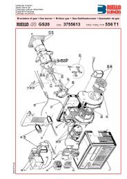
Technical description of the <strong>burner</strong>4.9 Burner description1 Flame stability disk2 Ignition electrodes3 Combustion head4 Gas pressure test point and head fixing screw5 Screw securing fan to sleeve6 OIL/GAS selector7 Relay8 Slide bars for opening the <strong>burner</strong> and inspecting the combustionhead9 Control box with lock-out pilot light and lock-out reset button10 Air gate valve11 Air inlet to fan12 Gas input pipework13 Gas butterfly valve14 Screw for combustion head adjustment15 Sleeve with flange for securing the <strong>burner</strong> to the b<strong>oil</strong>er16 Max. <strong>gas</strong> pressure switch17 Cell UV18 Servomotor controlling the <strong>gas</strong> butterfly valve and of air gatevalve (by means of a variable profile cam mechanism).When the <strong>burner</strong> is not operating the air gate valve is fullyclosed in order to reduce heat dispersion from the b<strong>oil</strong>er dueto the flue draught which draws air from the fan suction inlet.19 Fan motor20 Extensions for slide bars 8)21 Switch for: automatic - manual - off operationsButton for: increase - reduction power22 Motor contactor and thermal cut-out with reset button23 Bracket for mounting the power regulator RWF4024 Terminal strip25 Fairleads for electrical connections by installer26 Flame inspection window27 Minimum air pressure switch (differential operating type)28 Pump motor29 Pump30 Safety solenoid valve31 1 st and 2 nd stage valves32 Air pressure test pointTwo types of <strong>burner</strong> failure may occur:Control box lock-out:if the control box 9)(Fig. 6) pushbutton lights up, it indicates thatthe <strong>burner</strong> is in lock-out. To reset, press the pushbutton.Motor trip:release by pressing the pushbutton on thermal relay 22)(Fig. 6).D3168Fig. 64.10 Standard equipment1 - Gas train flange1 - Flange <strong>gas</strong>ket4 - Flange fixing screws (M10x40) to the butterfly valve1 - Thermal insulation screen4 - Screws (M16x40) to secure the <strong>burner</strong> sleeve with flange tothe b<strong>oil</strong>er2 - Hoses2 - Nipples for hoses with <strong>gas</strong>kets1 - Instruction booklet1 - Spare parts listWARNINGIn case of use with <strong>gas</strong> <strong>oil</strong> containing up to 10%Bio blend, it will be essential to use flexible <strong>oil</strong>lines suitable for bio <strong>fuel</strong> use.Please contact <strong>Riello</strong> for further information.2003336612 GB
Installation5 Installation5.1 Notes on safety for the installationAfter carefully cleaning all around the area where the <strong>burner</strong> willbe installed, and arranging the correct lighting of the environment,proceed with the installation operations.DANGERAll the installation, maintenance and disassemblyoperations must be carried out with the electricitysupply disconnected.WARNINGThe installation of the <strong>burner</strong> must be carried outby qualified personnel, as indicated in this manualand in compliance with the standards and regulationsof the laws in force.5.2 HandlingThe packaging of the <strong>burner</strong> includes a wooden platform, so it ispossible to move the <strong>burner</strong> (still packaged) with a transpallettruck or fork lift truck.WARNINGThe handling operations for the <strong>burner</strong> can behighly dangerous if not carried out with the greatestattention: keep any unauthorised people at adistance; check the integrity and suitableness ofthe available means of handling.Check also that the area in which you are workingis empty and that there is an adequate escapearea (i.e. a free, safe area to which you can quicklymove if the <strong>burner</strong> should fall).When handling, keep the load at not more than20-25 cm from the ground.CAUTIONAfter positioning the <strong>burner</strong> near the installationpoint, correctly dispose of all residual packaging,separating the various types of material.Before proceeding with the installation operations,carefully clean all around the area where the <strong>burner</strong>will be installed.5.3 Preliminary checksChecking the consignmentCAUTIONAfter removing all the packaging, check the integrityof the contents. In the event of doubt, do notuse the <strong>burner</strong>; contact the supplier.The packaging elements (wooden cage or cardboardbox, nails, clips, plastic bags, etc.) must notbe abandoned as they are potential sources ofdanger and pollution; they should be collected anddisposed of in the appropriate places.Checking the characteristics of the <strong>burner</strong>Check the identification label of the <strong>burner</strong>, showing: the model (A)(Fig. 7) and type of <strong>burner</strong> (B); the year of manufacture, in cryptographic form (C); the serial number (D); the data for electrical supply and the protection level (E); the electrical input power (F); the types of <strong>gas</strong> used and the relative supply pressures (G); the data of the <strong>burner</strong>’s minimum and maximum output possibilities(H) (see Firing rates)Warning. The output of the <strong>burner</strong> must be within theb<strong>oil</strong>er’s firing rate; the category of the device/countries of destination (I). <strong>gas</strong> <strong>oil</strong> (L) max. viscosity.R.B.L.DGAS-KAASUGAZ-AEPIOHEIZÖL FUELRIELLOS.p.A.I-37045 Legnago (VR) CED9243WARNINGLA B CEFGHGHI0085Fig. 7A <strong>burner</strong> label that has been tampered with, removedor is missing, along with anything else thatprevents the definite identification of the <strong>burner</strong>makes any installation or maintenance work difficult.2003336613 GB
Installation5.4 Installer/Servicer notes for the use of Gas <strong>oil</strong> with Bio blends up to 10%During the <strong>burner</strong> installation, check that the <strong>gas</strong><strong>oil</strong> and bio<strong>fuel</strong> blends are in accordance with <strong>Riello</strong> specifications(please refer to the chapters "Technical Data" and "Guidancefor the use of bio <strong>fuel</strong> blends up to 10%" within the<strong>burner</strong> technical manual).If a Bio blend is in use the installer must seek informationfrom the end user that their <strong>fuel</strong> supplier can evidence thatthe blends of <strong>fuel</strong> conform to the relevant standards.Check that the materials used in the construction of the <strong>oil</strong>tank and ancillary equipment are suitable for bio <strong>fuel</strong>s, If notthese must be upgraded or replaced with Bio compatibleparts.Particular attention should be given to the <strong>oil</strong> storage tankand supply to the <strong>burner</strong>. <strong>Riello</strong> recommends that existing<strong>oil</strong> storage tanks are cleaned, inspected and any traces ofwater are removed BEFORE bio <strong>fuel</strong> is introduced (Contactthe tank manufacturer or <strong>oil</strong> supplier for further advice). Ifthese recommendations are not respected this will increasethe risk of contamination and possible equipment failure.In line <strong>oil</strong> filters should be replaced making sure that theyare Bio compatible. <strong>Riello</strong> recommends a good quality biocompatible <strong>oil</strong> filter at the tank and a secondary 100 micronfilter are used to protect the <strong>burner</strong> pump and nozzle fromcontamination.The <strong>burner</strong> hydraulic components and flexible <strong>oil</strong> lines mustbe suitable for bio <strong>fuel</strong> use (check with <strong>Riello</strong> if in doubt).<strong>Riello</strong> have carefully chosen the specification of the biocompatible components including the flexible <strong>oil</strong> lines toprotect the pump, safety value and nozzle. The <strong>Riello</strong> warrantyis dependent upon the use of <strong>Riello</strong> genuine componentsincluding the <strong>oil</strong> lines, being used. The <strong>burner</strong> mustbe commissioned and combustion parameters set to appliancemanufacturer's recommendations.Regularly check visually for any signs of <strong>oil</strong> leakage fromseals, <strong>gas</strong>kets and hoses.It is strongly recommended that with Bio <strong>fuel</strong> use, <strong>oil</strong> filtersare inspected and replaced every 4 months. More regularlywhere contamination is experienced.During extended periods of non operation and/or where<strong>burner</strong>s are using <strong>oil</strong> as a standby <strong>fuel</strong>, it is strongly recommendedthat the <strong>burner</strong> is put into operation for shorts periodsat least every three months.5.5 Operating positionThe <strong>burner</strong> is designed to work only in the positions 1, 2, 3 and 4.Installation 1 is preferable, as it is the only one that allows performingmaintenance operations as described in this manual.Installations 2, 3 and 4 permit operation but make maintenanceand inspection of the combustion head difficult, page 33.WARNINGAny other position could compromise the correctworking of the appliance.Installation 5 is prohibited for safety reasons.12 3 4 5S8255Fig. 85.6 B<strong>oil</strong>er plateDrill the combustion chamber locking plate as shown in Fig. 9.The position of the threaded holes can be marked using the thermalscreen supplied with the <strong>burner</strong>.mm A B CRLS 190/M MZ 230 325 - 368 M 16Tab. DD455Fig. 92003336614 GB
Installation5.7 Blast tube lengthThe length of the blast tube must be selected according to the indicationsprovided by the manufacturer of the b<strong>oil</strong>er, and in anycase it must be greater than the thickness of the b<strong>oil</strong>er door completewith its fettling.The range of lengths available, L (mm), is as follows:Blast tube 12)(Fig. 10) Short LongRLS 190/M MZ 418 548For b<strong>oil</strong>ers with front flue passes 15)(Fig. 10) or flame inversionchambers, protective fettling in refractory material 13) must be insertedbetween the b<strong>oil</strong>er fettling 14) and the blast tube 12).This protective fettling must not compromise the extraction of theblast tube.For b<strong>oil</strong>ers having a water-cooled front the refractory fettling 13)-14)(Fig. 10) is not required unless it is expressly requested by theb<strong>oil</strong>er manufacturer.5.8 Securing the <strong>burner</strong> to the b<strong>oil</strong>erDetach the combustion head from the <strong>burner</strong>: disconnect the hoses by unscrewing the two connectors6)(Fig. 10). Disengage the articulated coupling 7) from the graduatedsector 8). Loosen the 4 screws 3) and remove the cover 1). Remove the screws 2) from the slide bars 5). Remove the 2 screws 4) and pull the <strong>burner</strong> back on slidebars 5) by about 100 mm. Disconnect the electrode wires and then pull the <strong>burner</strong>completely off the slide bars. Secure the sleeve with flange 11) to the b<strong>oil</strong>er plate, interposingthe thermal insulating screen 9) supplied with the<strong>burner</strong>. Use the 4 screws, also supplied with the unit, after first protectingthe thread with an anti-locking product.WARNINGThe seal between <strong>burner</strong> and b<strong>oil</strong>er must be airtight.D3171Fig. 105.9 Nozzle installation5.9.1 Choice of nozzles for 1 st and 2 nd stageThe <strong>burner</strong> complies with the emission requirements of theEN 267 standard.In order to guarantee that emissions do not vary, recommendedand/or alternative nozzles specified by <strong>Riello</strong> in the Instructionand warning booklet should be used.It is advisable to replace nozzles every yearduring regular maintenance operations.CAUTIONThe use of nozzles other than those specified by<strong>Riello</strong> S.p.A. and inadequate regular maintenancemay result into emission limits non-conforming tothe values set forth by the regulations in force, andin extremely serious cases, into potential hazardsto people and objects.The manufacturing company shall not be liable forany such damage arising from nonobservance ofthe requirements contained in this manual.WARNINGBoth nozzles must be chosen from among those listed in Tab. E.The first nozzle determines the delivery of the <strong>burner</strong> in the 1ststage.The second nozzle works together with the 1st nozzle to determinethe delivery of the <strong>burner</strong> in the 2nd stage.The deliveries of the 1st and 2nd stages must be contained withinthe value range indicated on page 9.2003336615 GB
InstallationUse nozzles with a 60° spray angle at the recommended pressureof 12 bar.As a rule the two nozzles have equal deliveries but the 1st stagenozzle may have a delivery less than 50% of the total deliverywhen a reduction of the counter-pressure peak is desired at themoment of starting (the <strong>burner</strong> allows good combustion ratesalso with a 40 - 100 % ratio between the 1st and 2nd stage).ExampleB<strong>oil</strong>er output = 1630 kW - efficiency 90 %Output required by the <strong>burner</strong>: 1630 : 0.9 = 1812 kWper nozzle:1812 : 2 = 906 kWtherefore, two equal, 60°, 12 bar nozzles are required:1° = 18 GPH - 2° = 18 GPH,or the following two different nozzles:1° = 16 GPH - 2° = 20 GPHGPH11.012.013.013.514.015.015.516.017.017.518.019.019.520.021.522.024.026.028.0kg/hkW10 bar 12 bar 14 bar 12 bar42.346.150.051.753.857.759.361.565.467.369.273.075.076.982.784.692.299.9107.646.750.955.157.059.463.665.567.972.174.276.480.682.784.891.293.3101.8110.3118.850.755.359.962.064.569.271.173.878.480.783.087.689.992.299.1101.4110.6119.9129.1553.9603.7653.5681.4704.5754.3782.3805.3855.1880.0906.1956.0980.91005.81081.71106.61207.31308.21409.0Tab. E5.9.2 Nozzle assembly Remove screw 1)(Fig. 11) and extract the internal part 2). Fit two nozzles with the box spanner (16 mm) 1)(Fig. 12),after having removed the plastic plugs 2). Fitting the spanner through the central hole in the flame stabilitydisk or loosen screws 1)(Fig. 13). Remove disk 2)(Fig. 13) and replace the nozzles using thewrench 3).WARNINGDo not use any sealing products such as <strong>gas</strong>kets,sealing compound, or tape.Be careful to avoid damaging the nozzle sealingseat. The nozzles must be screwed into placetightly but not to the maximum torque value providedby the wrench.D3172Fig. 11D1146Fig. 12D1147Fig. 132003336616 GB
InstallationThe nozzle for the 1 st stage of operation is the one lying beneaththe firing electrodes (Fig. 14).WARNINGMake sure that the electrodes are positioned asshown in Fig. 14. Refit the <strong>burner</strong> to the slide bars 3)(Fig. 15) at approximately100 mm from the sleeve 4) - <strong>burner</strong> positioned as shown inFig. 10 at page 15. Insert the ignition electrode cables and then slide the <strong>burner</strong>up to the sleeve so that it is positioned as shown in Fig. 15. Refit screws 2) on slide bars 3). Secure the <strong>burner</strong> to the sleeve by tightening screws 1). Connect the <strong>oil</strong> pipes again by screwing on the two connectors6)(Fig. 10 at page 15). Reconnect the articulation 7) to the graduated sector 5).WARNINGWhen fitting the <strong>burner</strong> on the two slide bars, it isadvisable to gently draw out the high tension cablesuntil they are slightly stretched.D2995Fig. 14D3174Fig. 155.10 ServomotorThe servomotor (Fig. 16) provides simultaneous adjustment ofthe air gate valve, by means of the variable profile cam, and the<strong>gas</strong> butterfly valve.The servomotor rotates through 130 degrees in 33 seconds.Do not alter the factory setting for the 5 cams; simply check thatthey are set as indicated below:– Cam I: 130°Limits rotation toward maximum position.When the <strong>burner</strong> is at max output the <strong>gas</strong> butterfly valve mustbe fully open: 90°.– Cam II: 0°Limits rotation toward the minimum position.When the <strong>burner</strong> is shut down the air gate valve and the <strong>gas</strong>butterfly valve must be closed: 0°.– Cam III: 30° (<strong>gas</strong>)Adjusts the ignition position and the MIN output.– Cam IV: 30° (<strong>oil</strong>)Adjusts the ignition position and the 1 st stage output.– Cam V: 90°Determines when the 2 nd stage diesel <strong>oil</strong> valve opens.D887Fig. 162003336617 GB
Installation5.11 Gas <strong>oil</strong> supplyWARNINGWARNINGDANGERCAUTIONWhere <strong>gas</strong> <strong>oil</strong> containing bio diesel is in use, it isrecommended to avoid over oxygenation of theblended <strong>fuel</strong>s.Where at all possible avoid the use of two pipesystems where the circulated <strong>fuel</strong> is returned tothe tank.If this cannot be avoided make sure that the returnpipe is normally below the surface of the <strong>fuel</strong> levelwithin the storage tank.In case of use with <strong>gas</strong> <strong>oil</strong> containing up to 10%Bio blend, it will be essential to use flexible <strong>oil</strong>lines suitable for bio <strong>fuel</strong> use.Please contact <strong>Riello</strong> for further information.It is strongly recommended a periodic check ofthe pump pressure operation (annually or betterevery six months, if the <strong>burner</strong> operation is continuous).You are advised to use additional filters on the <strong>fuel</strong>supply line.<strong>Riello</strong> recommends a good quality <strong>fuel</strong> filter at thetank (Fig. 17 - Fig. 18) and a secondary filter(100 for <strong>gas</strong> <strong>oil</strong> and 15 for kerosene) are usedto protect the <strong>burner</strong> pump and nozzle from contamination.In case of Biodiesel use, pay attention to installBiocompatible filters.5.11.1 Double-pipe circuitThe <strong>burner</strong> is equipped with a self-priming pump which is capableof feeding itself within the limits listed in the Tab. F.The tank higher than the <strong>burner</strong> A (Fig. 17)The distance "P" must not exceed 10 meters in order to avoidsubjecting the pump's seal to excessive strain; the distance "V"must not exceed 4 meters in order to permit pump self-primingeven when the tank is almost completely empty.The tank lower than the <strong>burner</strong> B (Fig. 17)Pump depression values higher than 0.45 bar (35 cm Hg) mustnot be exceeded because at higher levels <strong>gas</strong> is released fromthe <strong>fuel</strong>, the pump starts making noise and its working life-spandecreases.It is good practice to ensure that the return and suction lines enterthe <strong>burner</strong> from the same height; in this way it will be more improbablethat the suction line fails to prime or stops priming.5.11.2 The loop circuitA loop circuit consists of a loop of piping departing from and returningto the tank with an auxiliary pump that circulates the <strong>fuel</strong>under pressure.A branch connection from the loop goes to feed the <strong>burner</strong>.This circuit is extremely useful whenever the <strong>burner</strong> pump doesnot succeed in self-priming because the tank distance and/orheight difference are higher than the values listed in the Tab. F.66Key (Fig. 17)H Pump/Foot valve height differenceL Piping lengthø Inside pipe diameter1 Burner2 Pump3 Filter4 Manual on/off valve5 Suction line6 Foot valve7 Rapid closing manual valve remote controlled (only Italy)8 On/off solenoid valve (only Italy)9 Return line10 Check valve (only Italy)11 Tank filter+/- H L (meters)(meters) ø 8 mm ø 10 mm ø 12 mm+ 4+ 3+ 2+ 1+ 0.5716253444013812210690821501501501501500 36 74 137- 0.5- 1- 2- 3- 411 71110910 cm7D11078432281910-58V+H-HP5A9B6658422610131231098153252Fig. 17Tab. F2003336618 GB
Installation5.11.3 Single-pipe circuitIn order to obtain single-pipe working it is necessary to unscrewthe return hose, remove the by-pass screw 6)(Fig. 19) and thenscrew the plug 7)(Fig. 19).The distance “P” must not exceed 10 meters in order to avoidsubjecting the pump's seal to excessive strain; the distance "V"must not exceed 4 meters.For the priming pump loosen the screw 3)(Fig. 21) in order tobleed off the air contained in the suction line and wait until the <strong>fuel</strong>flows out.Key (Fig. 18)H Pump/Foot valve height differenceL Piping lengthø Inside pipe diameter1 Burner2 Pump3 Filter4 Manual on/off valve5 Suction line6 Foot valve7 Rapid closing manual valve remote controlled (only Italy)8 On/off solenoid valve (only Italy)11 Tank filter6+H L (meters)(meters) ø 8 mm ø 10 mm ø 12 mm43210.511 710 cmD110794716253444058V+HP5A1381221069082131501501501501502Fig. 18Tab. G5.12 Hydraulic system layoutKey Fig. 191 Pump suction2 Filter3 Pump4 Pressure governor5 Return pipe6 By-pass screw7 Pump return8 Safety solenoid9 1 st stage valve10 2 nd stage valve11 FilterM Pressure gaugeV VacuometerD3006Fig. 192003336619 GB
Installation5.13 Hydraulic connectionsThe pumps are equipped with a by-pass that connects return lineand suction line. The pumps are installed on the <strong>burner</strong> with theby-pass closed by screw 6)(Fig. 19).It is therefore necessary to connect both hoses to the pump.The pump will break immediately if it is run with the return lineclosed and the by-pass screw inserted. Remove the plugs from the suction and return connectionsof the pump. Insert the hose connections with the supplied seals into theconnections and screw them down. Take care that the hoses are not stretched or twisted duringinstallation. Install the hoses where they cannot be stepped on or comeinto contact with hot surfaces of the b<strong>oil</strong>er and where they donot hamper the opening of the <strong>burner</strong>. Now connect the other end of the hoses to the suction andreturn lines by using the supplied nipples.D3176Fig. 205.14 PumpWARNINGIn case of use with <strong>gas</strong> <strong>oil</strong> containing up to 10%Bio blend, it will be essential to use flexible <strong>oil</strong>lines suitable for bio <strong>fuel</strong> use.Please contact <strong>Riello</strong> for further information.D12515.14.1 Technical dataSuntec E7CCMin. delivery rate at 12 bar pressure kg/h 230Delivery pressure range bar 10 - 30Max. suction depression bar 0.45Viscosity range mm 2 /s (cSt) 3 - 75Max. <strong>gas</strong> <strong>oil</strong> temperature °C 90Max. suction and return pressure bar 1.5Pressure calibration in the factory bar 12Filter mesh width mm 0.17Tab. H1 Suction G 1/2”2 Return G 1/2”3 Pressure gauge attachment G 1/8”4 Vacuum meter attachment G 1/2”5 Pressure adjustment screw6 By-pass screwFig. 215.14.2 Pump primingBefore starting the <strong>burner</strong>, make sure that thetank return line is not clogged.Obstructions in the line could cause the sealingorgan located on the pump shaft to break.WARNING(The pump leaves the factory with the by-passclosed).– Also check to make sure that the valves located on the suctionline are open and that there is sufficient <strong>fuel</strong> in the tank.– For self-priming to take place, the screw 3)(Fig. 21) must beloosened in order to bleed off the air contained in the suctionline.– Start the <strong>burner</strong> by closing the control devices, with switch1)(Fig. 22) in the "MAN" position and with switch 6)(Fig. 6 atpage 12) in the "OIL" position.– The pump can be considered to be primed when the <strong>gas</strong> <strong>oil</strong>starts coming out of the screw 3)(Fig. 21).– Stop the <strong>burner</strong>: switch 1)(Fig. 22) set to "OFF" and tightenthe screw 3).2003336620 GB
Installation1 2The time required for this operation depends upon the diameterand length of the suction tubing.If the pump fails to prime at the first starting of the <strong>burner</strong> and the<strong>burner</strong> locks out, wait approx. 15 seconds, reset the <strong>burner</strong>, andthen repeat the starting operation as often as required.After 5 or 6 starting operations allow 2 or 3 minutes for the transformerto cool.Do not illuminate the UV cell or the <strong>burner</strong> will lock out; the <strong>burner</strong>should lock out anyway about 10 seconds after it starts.WARNINGD791Fig. 22The a.m. operation is possible because the pumpis already full of <strong>fuel</strong> when it leaves the factory.If the pump has been drained, fill it with <strong>fuel</strong>through the opening on the vacuum meter prior tostarting; otherwise, the pump will seize.Whenever the length of the suction piping exceeds20-30 meters, the supply line must be filledusing a separate pump.2003336621 GB
Installation5.15 Gas supply5.15.1 Gas lineThe <strong>gas</strong> train must be connected to the <strong>gas</strong> attachment1)(Fig. 23), using flange 2), <strong>gas</strong>ket 3) and screws 4) supplied withthe <strong>burner</strong>.The <strong>gas</strong> train can enter the <strong>burner</strong> from the right or left side, dependingon which is the most convenient, see Fig. 23.Gas solenoids 8)-9)(Fig. 24) must be as close as possible to the<strong>burner</strong> to ensure <strong>gas</strong> reaches the combustion head within thesafety time range of 2 s.Make sure that the pressure governor calibration range (colour ofthe spring) comprises the pressure required by the <strong>burner</strong>.D3002Fig. 23D3003Key Fig. 241 Gas input pipe2 Manual valve3 Vibration damping joint4 Pressure gauge with pushbutton cock5 Filter6 Pressure governor (vertical)7 Minimum <strong>gas</strong> pressure switch8 Safety solenoid VS (vertical)9 Adjustment solenoid VR (vertical)Two adjustments:- ignition delivery (rapid opening)- maximum delivery (slow opening)10 Standard issue <strong>burner</strong> <strong>gas</strong>ket11 Gas adjustment butterfly valve12 Burner13 Gas valve 8)-9) leak detection control device.In accordance with EN 676 Standards, <strong>gas</strong> valve leak detectioncontrol devices are compulsory for <strong>burner</strong>s with maximumoutputs of more than 1200 kW.14 Gas train/<strong>burner</strong> adaptor15 Maximum <strong>gas</strong> pressure switchP1 Pressure at combustion headP2 Pressure down-line from the pressure governorP3 Pressure up-line from the filterL Gas train supplied separately with the code indicated inTab. JL1 The responsability of the installerGAS TRAIN COMPONENTSCode 5 6 7 - 83970146397016039701813970182397014739701613970148397016239701493970163Fig. 24GF 520/1 FRS 520 DMV-DLE 520/11Multiblock MB DLE 420GF 40065/3 FRS 5065 DMV-DLE 5065/11GF 40080/3 FRS 5080 DMV-DLE 5080/11GF40100/3 FRS 5100 DMV-DLE 5100/11Tab. I2003336622 GB
Installation5.15.2 Gas trainIt is type-approved according to EN 676 Standards and is suppliedseparately from the <strong>burner</strong> with the code indicated in Tab. J.Gas train - L (Fig. 24) 13 14Ø C.T. Code Code Code2” - 3970146 3010123 -2” 3970160 - -2” - 3970181 3010123 -2” 3970182 - -DN 65 - 3970147 3010123 3000825DN 65 3970161 - 3000825DN 80 - 3970148 3010123 3000826DN 80 3970162 - 3000826DN 100 - 3970149 3010123 3000826DN 100 3970163 - 3010127Tab. JKey Tab. JC.T. Gas valves 8) - 9) leak detection control devices:- Gas train without <strong>gas</strong> valve leak detection control device;device that can be ordered separately and assembled subsequently(see Column 13). Gas train with assembled VPS valve leak detection controldevice.13 VPS valve leak detection control device.Supplied separately from <strong>gas</strong> train on request.14 Gas train/<strong>burner</strong> adaptor.Supplied separately from <strong>gas</strong> train on request.NoteSee the accompanying instructions for the adjustment of the <strong>gas</strong>train.5.15.3 Gas pressureThe Tab. K shows minimum pressure losses along the <strong>gas</strong> supplyline depending on the maximum <strong>burner</strong> output operation.kW1p (mbar)2p (mbar)39701463970160397018139701823 p (mbar)3970147397016139701483970162397014939701631100 7.0 1.1 22.5 20.0 8.5 4.5 -1200 8.3 1.4 27.0 23.5 10.0 5.4 -1300 9.6 1.7 32.0 27.5 12.0 6.0 -1400 10.8 2.0 35.0 29.0 15.0 7.0 -1500 12.1 2.2 40.0 32.0 16.0 8.0 -1600 13.4 2.5 45.0 35.0 17.0 9.0 4.51700 14.6 2.8 52.0 38.5 19.0 10.0 4.71800 16.0 3.0 58.0 42.0 21.0 11.0 5.01900 17.0 3.2 63.0 46.0 23.0 12.0 5.82000 18.3 3.4 68.0 50.0 25.0 13.0 6.12150 21.2 3.9 74.0 53.0 27.5 14.0 6.8Tab. KColumn 1 (Tab. K)Pressure loss at combustion head.Gas pressure measured at test point 1)(Fig. 25), with:– combustion chamber at 0 mbar;– combustion head adjusted as indicated in diagram (Fig. 29 atpage 27).Column 2 (Tab. K)Pressure loss at <strong>gas</strong> butterfly valve 2)(Fig. 25) with maximumopening: 90°.Column 3 (Tab. K)Pressure loss of <strong>gas</strong> train 3)(Fig. 25) includes:– adjustment valve VR– safety valve VS (both fully open)– pressure governor R– filter F (see components in Tab. I at page 22).The values shown in the Tab. K refer to:natural <strong>gas</strong> G 20 PCI 10 kWh/Nm 3 (8,6 Mcal/Nm 3 )With:natural <strong>gas</strong> G 25 PCI 8,6 kWh/Nm3 (7,4 Mcal/Nm 3 ) multiply tabulatedvalues:• column 1: by 1.3• column 2-3: by 1.49Calculate the approximate maximum output of the <strong>burner</strong> thus:– subtract the combustion chamber pressure from the <strong>gas</strong>pressure measured at test point 1)(Fig. 25).– Find the nearest pressure value to your result in column 1 ofthe Tab. K.– Read off the corresponding output on the left.Example:• Maximum output operation• Natural <strong>gas</strong> G 20 PCI 10 kWh/Nm 3• Gas pressure at test point 1)(Fig. 25) = 16.0 mbar• Pressure in combustion chamber = 3.0 mbar16.0 - 3.0 = 13.0 mbarA maximum output of 1600 kW shown in Tab. K corresponds to13.0 mbar pressure, column 1.This value serves as a rough guide, the effective delivery must bemeasured at the <strong>gas</strong> meter.2003336623 GB
InstallationTo calculate the required <strong>gas</strong> pressure at test point 1)(Fig. 25),set the maximim output required from the <strong>burner</strong> operation:– Find the nearest output value in the Tab. K.– Read off the pressure at test point 1)(Fig. 25) on the right incolumn 1.– Add this value to the estimated pressure in the combustionchamber.Example:• Required <strong>burner</strong> maximum output operation: 1600 kW• Natural <strong>gas</strong> G 20 PCI 10 kWh/Nm 3• Gas pressure at <strong>burner</strong> output of 1600 kW,column 1 = 13.0 mbar• Pressure in combustion chamber = 3.0 mbar13.0 + 3.0 = 16.0 mbarpressure required at test point 1)(Fig. 25).D3177Fig. 252003336624 GB
Electrical system6 Electrical system6.1 Notes on safety for the electrical wiringDANGERThe electrical wiring must be carried out with the electrical supply disconnected.Electrical wiring must be carried out by qualified personnel and in compliance with the regulations currently inforce in the country of destination. Refer to the wiring diagrams.The manufacturer declines all responsibility for modifications or connections different from those shown in thewiring diagrams.Do not invert the neutral with the phase in the electrical supply line. Any inversion would cause a lockout due tofiring failure.Check that the electrical supply of the <strong>burner</strong> corresponds to that shown on the identification label and in thismanual.The <strong>burner</strong>s have been set for intermittent operation. This means they should compulsorily be stopped at leastonce every 24 hours to enable the control box to perform checks of its own start-up efficiency. Normally theb<strong>oil</strong>er's thermostat/pressure switch ensures the stopping of the <strong>burner</strong>.If this is not the case, it is necessary to apply in series with IN a timer switch that turns off the <strong>burner</strong> at least onceevery twenty-four hours. Refer to the wiring diagrams.The electrical safety of the device is obtained only when it is correctly connected to an efficient earthing system,made according to current standards. It is necessary to check this fundamental safety requirement. In the eventof doubt, have the electrical system checked by qualified personnel.The electrical system must be suitable for the maximum input power of the device, as indicated on the label andin the manual, checking in particular that the section of the cables is suitable for the input power of the device.For the main power supply of the device from the electricity mains:- do not use adapters, multiple sockets or extensions;- use an omnipolar switch, as indicated by the current safety standards.Do not touch the device with wet or damp body parts and/or in bare feet.Do not pull the electric cables.Before carrying out any maintenance, cleaning or checking operations:DANGERdisconnect the electrical supply from the <strong>burner</strong> bymeans of the main system switch;6.2 Electrical connectionsDANGERisolate the <strong>fuel</strong> supply.If the cover is still present, remove it and proceed with the electricalwiring according to the wiring diagrams.Electrical wiring must be made in accordance withthe regulations currently in force in the country ofdestination and by qualified personnel.WARNING <strong>Riello</strong> S.p.A. declines all liability for modificationsor connections other than those shown on thesediagrams.Use flexible cables according to EN 60 335-1. Regulations:– if in PVC sheath, use at least H05 VV-F;– if in rubber sheath, use at least H05 RR-F.All the wires to connect to the <strong>burner</strong> terminal strip 8)(Fig. 26)must enter through the supplied fairleads.The fairleads and hole press-outs can be used in various ways;the following lists show one possible solution:1 Pg 13.5 Three-phase power supply2 M20 7 pole socket input3 M20 4 pole socket input4 M20 6 pole socket input5 Optional holes6 Open the hole, if necessary add a cable gland7 6 pole socket for <strong>gas</strong> valves, <strong>gas</strong> pressure switch or devicefor VPS control8 Terminal strip9 4 pole socket for TR thermostat/pressure switch10 7 pole socket single-phase power supply for TR thermostat/pressure switch98107D11080Fig. 262003336625 GB
Electrical system6.2.1 Calibration of thermal cut-outModelRLS 190/M MZ - 230 VRLS 190/M MZ - 400 V16 A9.5 A6.3 Current to the UV photocellMin. value for a good work: 70 µA.If the value is lower, it can depend on:– exhausted photocell– low current (lower than 187V)– bad regulation of the <strong>burner</strong>In order to measure the current, use a microammeter of 100 µAc.c., connected to the photocell, as in the scheme, with a capacitorof 100 µF - 1V c.c. at the same level of the instrument.See Fig. 27.D1143Fig. 272003336626 GB
Start-up, calibration and operation of the <strong>burner</strong>7 Start-up, calibration and operation of the <strong>burner</strong>7.1 Notes on safety for the first start-upWARNINGThe first start-up of the <strong>burner</strong> must be carried outby qualified personnel, as indicated in this manualand in compliance with the standards and regulationsof the laws in force.WARNINGCheck the correct working of the adjustment, commandand safety devices.7.2 Adjustment before first firing (<strong>gas</strong> <strong>oil</strong> operation)7.2.1 Combustion head settingThe setting of the combustion head depends exclusively on themaximum <strong>burner</strong> output.Turn screw 5)(Fig. 28) until the notch shown in diagram (Fig. 29)is level with the front surface of flange 6).WARNINGIn order to facilitate adjustment, loosen screw1)(Fig. 11 at page 16), adjust and then tighten.Example:Maximum <strong>burner</strong> output = 1400 kW.If diagram (Fig. 29) is consulted it is clear that for this delivery, thecombustion head must be adjusted using notch 4, as shown inFig. 28.Notches no.D1149D3173Fig. 287.2.2 Pump adjustmentNo settings are required for the pump, which is set to 12 bar bythe manufacturer. This pressure must be checked and adjusted(if required) after the <strong>burner</strong> has been ignited.The only operation required in this phase is the application of apressure gauge on the appropriate pump attachment.7.2.3 Fan gate adjustmentThe first time the <strong>burner</strong> is fired leave the factory setting unchangedfor both 1 st stage and 2 nd stage operation.Burner outputFig. 297.3 Burner calibration (<strong>gas</strong> <strong>oil</strong> operation)WARNINGIt is advisable to first set the <strong>burner</strong> for operatingon <strong>oil</strong> and then for <strong>gas</strong>.Execute the <strong>fuel</strong> exchange when the <strong>burner</strong> is off.1 27.3.1 FiringSet switch 1)(Fig. 30) to "MAN".During the first firing, during the passage from the 1 st to the 2 ndstage, there is a momentary lowering of the <strong>fuel</strong> pressure causedby the filling of the 2 nd stage nozzle tubing.This lowering of the <strong>fuel</strong> pressure can cause the <strong>burner</strong> to lockoutand can sometimes give rise to pulsations.Once the following adjustments have been made, the firing of the<strong>burner</strong> must generate a noise similar to the noise generated duringoperation.D791Fig. 302003336627 GB
Start-up, calibration and operation of the <strong>burner</strong>7.3.2 OperationThe optimum calibration of the <strong>burner</strong> requires an analysis of theflue <strong>gas</strong>es at the b<strong>oil</strong>er outlet and interventions on the followingpoints.1 st and 2 nd stage nozzlesSee the information listed on page 15.Combustion headThe adjustment of the combustion head already carried out(page 27) need not be altered unless the 2 nd stage delivery of the<strong>burner</strong> is changed.Pump pressure12 bar: this is the pressure calibrated in the factory which isusually sufficient for most purposes.Sometimes, this pressure must be adjusted to:10 bar: in order to reduce <strong>fuel</strong> delivery.This adjustment is possible only if the surrounding temperatureremains above 0°C.14 bar: in order to increase <strong>fuel</strong> delivery or to ensure firingseven at temperatures of less than 0°C. In order to adjustpump pressure, use the screw 5)(Fig. 21 at page 20).1 st and 2 nd stage fan air gate valveSee adjustments of servomotor at page 17.7.4 Adjustment before first firing (<strong>gas</strong> operation)Adjustment of the combustion head has been illustrated onpage 27.In addition, the following adjustments must also be made: open manual valves up-line from the <strong>gas</strong> train. Adjust the minimum <strong>gas</strong> pressure switch to the start of thescale (Fig. 31). Adjust the maximum <strong>gas</strong> pressure switch to the start of thescale (Fig. 32). Adjust the air pressure switch to the zero position of thescale (Fig. 33). Purge the air from the <strong>gas</strong> line.Continue to purge the air (we recommend using a plastictube routed outside the building) until <strong>gas</strong> is smelt. Fit a U-type manometer (Fig. 34) to the <strong>gas</strong> pressure testpoint on the sleeve. The manometer readings are used tocalculate the MAX. <strong>burner</strong> power using the Tab. K atpage 23. Connect two lamps or testers to the two <strong>gas</strong> line solenoidvalves VR and VS to check the exact moment at which voltageis supplied.This operation is unnecessary if each of the two solenoidvalves is equipped with a pilot light that signals voltage passingthrough.Before starting up the <strong>burner</strong> it is good practice to adjust the <strong>gas</strong>train so that ignition takes place in conditions of maximum safety,i.e. with <strong>gas</strong> delivery at the minimum.D66D521Fig. 32Fig. 33D896Fig. 31D3178Fig. 342003336628 GB
Start-up, calibration and operation of the <strong>burner</strong>7.5 Burner starting (<strong>gas</strong> operation)WARNINGIt is advisable to first set the <strong>burner</strong> for operatingon <strong>oil</strong> and then for <strong>gas</strong>.Execute the <strong>fuel</strong> exchange when the <strong>burner</strong> is off.Close the control devices and set switch 1)(Fig. 35) to “MAN”.As soon as the <strong>burner</strong> starts check the direction of rotation of thefan blade, looking through the flame inspection window 26)(Fig. 6at page 12).Make sure that the lamps or testers connected to the solenoids,or pilot lights on the solenoids themselves, indicate that no voltageis present. If voltage is present, then immediately stop the<strong>burner</strong> and check electrical connections.D7911 2Fig. 357.6 Burner firing (<strong>gas</strong> operation)Having completed the checks indicated in the previous heading,the <strong>burner</strong> should fire. If the motor starts but the flame does notappear and the control box goes into lock-out, reset and wait fora new firing attempt.If firing is still not achieved, it may be that <strong>gas</strong> is not reaching thecombustion head within the safety time period of 3 seconds.In this case increase <strong>gas</strong> firing delivery.The arrival of <strong>gas</strong> at the sleeve is indicated by the U-type manometer(Fig. 34).Once the <strong>burner</strong> has fired, now proceed with global calibrationoperations.7.7 Burner calibration (<strong>gas</strong> operation)The optimum calibration of the <strong>burner</strong> requires an analysis of theflue <strong>gas</strong>es at the b<strong>oil</strong>er outlet.Adjust successively– First firing output– MAX <strong>burner</strong> output– MIN <strong>burner</strong> output– Intermediate outputs– Air pressure switch– Maximum <strong>gas</strong> pressure switch– Minimum <strong>gas</strong> pressure switch7.7.1 Firing outputAccording to EN 676 Regulations:<strong>Burners</strong> with MAX output up to 120 kWFiring can be performed at the maximum operation output level.Example:– max. operation output : 120 kW– max. firing output : 120 kW<strong>Burners</strong> with MAX output above 120 kWFiring must be performed at a lower output than the max. operationoutput. If the firing output does not exceed 120 kW, no calculationsare required. If firing output exceeds 120 kW, theregulations prescribe that the value be defined according to thecontrol box safety time “ts”:– for ts = 2s, firing output must be equal to or lower than 1/2 ofmax. operation output;– for ts = 3s, firing output must be equal to or lower than 1/3 ofmax. operation output.Example:MAX operation output of 600 kW.Firing output must be equal to or lower than:– 300 kW con ts = 2s– 200 kW con ts = 3sIn order to measure the firing output: remove the UV cell 17)(Fig. 6 at page 12) (the <strong>burner</strong> will fireand then go into lock-out after the safety time has elapsed). Perform 10 firings with consecutive lock-outs. On the meter read the quantity of <strong>gas</strong> burned. This quantitymust be equal to or lower than the quantity given by the formula:Nm 3 /h (max. <strong>burner</strong> delivery)360Example for G 20 (10 kWh/Nm 3 ):max. operation output: 600 kW corresponding to 60 Nm 3 /h.After 10 firings with lock-outs, the delivery read on the meter mustbe equal to or lower than: 60 : 360 = 0.166 Nm 3 .7.7.2 MAX <strong>burner</strong> outputMax. output of the <strong>burner</strong> must be set within the firing rate rangeshown on page 11.In the above instructions we left the <strong>burner</strong> running in MIN. outputoperation. Now press button 2)(Fig. 35) “increase output” andkeep it pressed until the servomotor has opened the air gatevalve and the <strong>gas</strong> butterfly valve.Gas calibrationMeasure the <strong>gas</strong> delivery at the meter.A guideline indication can be calculated from the Tab. K atpage 23, simply read off the <strong>gas</strong> pressure on the U-type manometer,see Fig. 34 at page 28, and follow the instructions onpage 23.– If delivery needs to be reduced, diminish outlet <strong>gas</strong> pressureand, if it is already very low, slightly close adjustment valveVR.– If delivery needs to be increased, increase outlet <strong>gas</strong> pressure.Adjusting air deliveryProgressively adjust the end profile of cam 4)(Fig. 36) by turningthe screws 7).– Turn the screws clockwise to increase air delivery.– Turn the screws counter-clockwise to reduce air delivery.2003336629 GB
Start-up, calibration and operation of the <strong>burner</strong>D1710D889Fig. 37Key Fig. 361 Servomotor2 Servomotor 1) - Cam 4): engaged3 Servomotor 1) - Cam 4): disengaged4 Adjustable profile cam5 Cam starting profile adjustment screws6 Adjustment fixing screws7 Cam end profile adjustment screws8 Graduated sector for <strong>gas</strong> butterfly valve9 Index for graduated sector 810 Key for cam III adjustment7.7.3 MIN <strong>burner</strong> outputMin output must be selected within the firing rate range shown onpage 11.Press button 2)(Fig. 35 at page 29) “output reduction” until theservomotor has closed the air gate valve and the <strong>gas</strong> butterfluvalve to 30° (factory set adjustment).Adjusting <strong>gas</strong> deliveryMeasure the delivery of <strong>gas</strong> from the <strong>gas</strong> meter.– If this value is to be reduced, decrease the angle of cam III(Fig. 37) slightly by proceeding a little at a time until the angleis changed from 30° to 28° - 26°....– If it has to be increased press the button “output increase”2)(Fig. 35 at page 29) (i.e. open the <strong>gas</strong> butterfly valve by 10-15°), increase the cam III angle (Fig. 37) with small successivemovements, i.e. take it from angle 30° to 32° - 34°....Then press the button “output decrease” until the servomotoris taken to the minimum opening position and measure the<strong>gas</strong> delivery.WARNINGFig. 36The servomotor follows the adjustment of cam IIIonly when the cam angle is reduced. If it is necessaryto increase the cam angle, first increase theservomotor angle with the key “output increase”,then increase the cam III angle, and finally bringthe servomotor back to the MIN output positionwith the key ”output decrease”.In order to adjust cam III, especially for fine movements, the key10)(Fig. 36), held by a magnet under the servomotor, can beused.Adjustment of air deliveryProgressively adjust the starting profile of cam 4)(Fig. 36) by turningthe screws 5).It is preferable not to turn the first screw since this is used to setthe air gate valve to its fully-closed position.7.7.4 Intermediate outputsAdjustment of <strong>gas</strong> deliveryNo adjustment of <strong>gas</strong> delivery is requiredAdjustment of air deliveryPress the key 2)(Fig. 35 at page 29) “output increase” a little sothat the servomotor turns by about 15°.Adjust the screws until optimal combustion is obtained. Proceedin the same way with the other screws.WARNING Switch off the <strong>burner</strong> using switch 1)(Fig. 35 at page 29), atOFF position; disengage the cam 4)(Fig. 36) from the servomotor, bypressing the button 3)(Fig. 37) and moving it to the right, andcheck more than once that the movement is soft andsmooth, and does not grip, by rotating the cam 4) forwardand backward by hand. Engage the cam 4) to the servomotor again by moving thebutton 2)(Fig. 37) to the left.WARNINGTake care that the cam profile variation is progressive.As far as is possible, try not to move those screwsat the ends of the cam that were previously adjustedfor the opening of the air gate to MAX and MINoutput. Finally fix the adjustment by turning the screws 6)(Fig. 36).NOTE:Once you have finished adjusting outputs MAX - MIN - INTER-MEDIATE, check ignition once again: noise emission at thisstage must be identical to the following stage of operation.If you notice any sign of pulsations, reduce the ignition stage delivery.2003336630 GB
Start-up, calibration and operation of the <strong>burner</strong>7.7.5 Air pressure switchAdjust the air pressure switch after having performed all other<strong>burner</strong> adjustments with the air pressure switch set to the start ofthe scale (Fig. 38).With the <strong>burner</strong> operating at min. output, increase adjustmentpressure by slowly turning the relative knob clockwise until the<strong>burner</strong> locks out.Then turn the knob anti-clockwise by about 20% of the set pointand repeat <strong>burner</strong> starting to ensure it is correct.If the <strong>burner</strong> locks out again, turn the knob anti-clockwise a littlebit more.WARNINGThe air pressure switch is of the differential type. If a negativepressure in the combustion chamber during pre-purging preventsthe air pressure switch from closing, fit a tube between the airpressure switch and the suction inlet of the fan.WARNINGAs a rule, the air pressure switch must prevent theair pressure from lowering below 80% of the adjustmentvalue as well as preventing the CO in thefumes from exceeding 1% (10,000 ppm).To check this, insert a combustion analyser intothe chimney, slowly close the fan suction inlet (forexample with cardboard) and check that the <strong>burner</strong>locks out, before the CO in the fumes exceeds1%.The use of the air pressure switch with differentialoperation is allowed only in industrial applicationsand in places where national rules enable the airpressure switch to control only fan operation.7.7.6 Maximum <strong>gas</strong> pressure switchAdjust the maximum <strong>gas</strong> pressure switch after having performedall the other <strong>burner</strong> adjustments with the maximum <strong>gas</strong> pressureswitch set at the end of the scale (Fig. 39).With the <strong>burner</strong> operating at MAX output, reduce the adjustmentpressure by slowly turning the relative knob anticlockwise untilthe <strong>burner</strong> locks out.Then turn the knob clockwise by 2 mbar and repeat <strong>burner</strong> firing.If the <strong>burner</strong> locks out again, turn the knob again clockwise by 1mbar.7.7.7 Minimum <strong>gas</strong> pressure switchAdjust the minimum <strong>gas</strong> pressure switch after having performedall the other <strong>burner</strong> adjustments with the pressure switch set atthe start of the scale (Fig. 40).With the <strong>burner</strong> operating at MAX output, increase adjustmentpressure by slowly turning the relative knob clockwise until the<strong>burner</strong> locks out.Then turn the knob anti-clockwise by 2 mbar and repeat <strong>burner</strong>starting to ensure it is uniform.If the <strong>burner</strong> locks out again, turn the knob anti-clockwise againby 1 mbar.D521D66D896Fig. 38Fig. 39Fig. 402003336631 GB
Start-up, calibration and operation of the <strong>burner</strong>7.8 Combustion checksCO 2It is better to set the <strong>burner</strong> with CO 2 not higer than 10% (<strong>gas</strong> withPci 8,600 kcal/m 3 ).In this way avoiding a loss of calibration setting (for example draftvariation) that could cause combustion with little air and the productionof CO.COIt must be not higher than 100 mg/kWh.7.9 Burner operationNORMAL FIRING(n° = seconds from instant 0)7.9.1 Burner flame goes out during operationIf the flame should accidentally go out during operation, the <strong>burner</strong>will lock out within 1s.D3202Fig. 41NO FIRINGD3203Key Fig. 41 - Fig. 421 Thermostat2 Motor3 Air gate valve4 Ignition transformer5 First valve6 First flame7 Second valve8 Second flame9 Lock-outFig. 422003336632 GB
Maintenance8 Maintenance8.1 Notes on safety for the maintenanceThe periodic maintenance is essential for the good operation,safety, yield and duration of the <strong>burner</strong>.It allows you to reduce consumption and polluting emissions andto keep the product in a reliable state over time.DANGERThe maintenance interventions and the calibrationof the <strong>burner</strong> must only be carried out by qualified,authorised personnel, in accordance with the contentsof this manual and in compliance with thestandards and regulations of current laws.Before carrying out any maintenance, cleaning or checking operations:DANGERDANGERDisconnect the electrical supply from the <strong>burner</strong>by means of the main system switch.Close the <strong>fuel</strong> interception tap.8.2 Maintenance programme8.2.1 Maintenance frequencyThe combustion system should be checked at least once ayear by a representative of the manufacturer or anotherspecialised technician.Flame inspection windowClean the flame inspection window (Fig. 43).8.2.2 Checking and cleaningCombustionThe optimum calibration of the <strong>burner</strong> requires an analysis of theflue <strong>gas</strong>es.Significant differences with respect to the previous measurementsindicate the points where more care should be exercisedduring maintenance.Combustion headOpen the <strong>burner</strong> and make sure that all components of the combustionhead are in good condition, not deformed by the hightemperatures, free of impurities from the surroundings and correctlypositioned. If in doubt, disassemble the elbow fitting5)(Fig. 44).UV cellClean the glass cover from any dust that may have accumulated.The UV cell 17)(Fig. 6 at page 12) is held in position by a pressurefit and can therefore be removed by pulling it outward forcefully.FanCheck to make sure that no dust has accumulated inside the fanor on its blades, as this condition will cause a reduction in the airflow rate and provoke polluting combustion.BurnerCheck for excess wear or loose screws in the mechanisms controllingthe air gate valve and the <strong>gas</strong> butterfly valve.Also make sure that the screws securing the electrical leads inthe <strong>burner</strong> terminal strip are fully tightened.Clean the outside of the <strong>burner</strong>, taking special care with the transmissionjoints and cam 4)(Fig. 36 at page 30).B<strong>oil</strong>erClean the b<strong>oil</strong>er as indicated in its accompanying instructions inorder to maintain all the original combustion characteristics intact,especially the flue <strong>gas</strong> temperature and combustion chamberpressure.D484ServomotorDisengage the cam 4)(Fig. 36 at page 30) from the servomotor,by pressing and moving button 3)(Fig. 37 at page 30) towards theright, and turn it backwards and forwards by hand to make sure itmoves freely.Now engage the cam again by moving the button 2)(Fig. 37 atpage 30) to the left.GAS OIL OPERATIONFig. 43FiltersCheck the filtering baskets on line and at nozzle present in thesystem. Clean or replace if necessary.If rust or other impurities are observed inside the pump, use aseparate pump to lift any water and other impurities that mayhave deposited on the bottom of the tank.PumpThe delivery pressure must be stable. The depression must beless than 0.4 bar. Unusual noise must not be evident during pumpoperation.If the pressure is found to be unstable or if the pump runs noisily,the flexible hose must be detached from the line filter and the <strong>fuel</strong>must be sucked from a tank located near the <strong>burner</strong>. This meas-2003336633 GB
Maintenanceure permits the cause of the anomaly to be traced to either thesuction piping or the pump.If the pump is found to be responsible, check to make sure thatthe filter is not dirty. The vacuometer is installed upstream fromthe filter and consequently will not indicate whether the filter isclogged or not. Contrarily, if the problem lies in the suction line,check to make sure that the filter is clean and that air is not enteringthe piping.Please check that the supply line and filters are clear. The use ofa pump vacuum gauge will assist in this. This measure permitsthe cause of the anomaly to be traced to either the suction line orthe pump.If the problem lies in the suction line, check to make sure that thefilter is clean and that air is not entering the piping.Hoses Check periodically the flexible pipes conditions. They haveto be replaced at least every 2 years. In case of use of <strong>gas</strong> <strong>oil</strong> and bio <strong>fuel</strong> blends, it is strongly recommendedto inspect even more frequently the hoses andreplace them where contamination has occurred. Check to make sure that the hoses are still in good condition.NozzlesDo not clean the nozzle openings; do not even open them.The nozzle filters however may be cleaned or replaced as required.It is advisable to replace nozzles every year during regular maintenanceoperations.Combustion must be checked after the nozzles have beenchanged.GAS OPERATIONGas leaksMake sure that there are no <strong>gas</strong> leaks on the pipework betweenthe <strong>gas</strong> meter and the <strong>burner</strong>.Gas filterChange the <strong>gas</strong> filter when it is dirty.CombustionIn case the combustion values found at the beginning of the interventiondo not respect the standards in force or, in any case, donot correspond to a proper combustion, contact the TechnicalAssistant and have him carry out the necessary adjustments.GASEN 676Max output 1,2Theoretical max. CalibrationCO 2CO 2 %0 % O 2 = 1,2 = 1,3Excess airMin output 1,3COmg/kWhG 20 11.7 9.7 9.0 100G 25 11.5 9.5 8.8 100G 30 14.0 11.6 10.7 100G 31 13.7 11.4 10.5 100Fuel tankIf water or contamination is present within the <strong>fuel</strong> tank, it is essentialthat this is removed before the equipment is to be used.This is extremely important when <strong>gas</strong> <strong>oil</strong> containing Bio diesel isin use. If in doubt about how to achieve this then please contactthe <strong>fuel</strong> or <strong>oil</strong> tank supplier.CombustionIn case the combustion values found at the beginning of the interventiondo not respect the standards in force or, in any case, donot correspond to a proper combustion, contact the TechnicalAssistant and have him carry out the necessary adjustments.EN 267Max output 1.2Excess airMin output 1.3Theoretical max. CO 2Calibration CO 2 % CO0 % O 2 = 1,2 = 1,3 mg/kWh15.2 12.6 11.5 1002003336634 GB
Maintenance8.3 Opening the <strong>burner</strong>DANGERDisconnect the electrical supply from the<strong>burner</strong>. Loosen screws 1)(Fig. 44) and withdraw the cover 2). Disconnect the hoses 7). Disengage the articulated coupling 8) from the graduatedsector 9). Remove the screws 10) from the two slide bars 4). Fit the two extensions onto the slide bars 4). Replace the screws 10) onto the two slide bars. Remove screws 3) and pull the <strong>burner</strong> back by about100 mm on the slide bars. Disconnect the electrode leads and then pull the <strong>burner</strong> fullyback. Now extract the internal part 5) after having removed thescrew 6).D3179Fig. 448.4 Closing the <strong>burner</strong> Push the <strong>burner</strong> until it is about 100 mm from the sleeve. Re-connect the leads and slide in the <strong>burner</strong> until it comes toa stop. Refit screws 3), and pull the probe and electrode leads gentlyout until they are slightly stretched. Re-couple the articulated coupling 8) to the graduated sector9). Reconnect the light-<strong>oil</strong> pipes 7). Remove the two extensions from the slide bars 4) and returnthem to their original position.2003336635 GB
Faults - Possible causes - Solutions9 Faults - Possible causes - SolutionsFind a list of faults, causes and possible solutions for a set of failures that may occur and result in irregular <strong>burner</strong> operation or nofunctioning at all.If a <strong>burner</strong> malfunction is detected, first of all:• check that the electrical wiring is adequately connected;• check whether <strong>fuel</strong> is delivered;• check that every adjustment parameter is adequately set.GAS OIL OPERATIONSYMBOL (1) FAULT PROBABLE CAUSE SUGGESTED REMEDYP1The <strong>burner</strong> does not start A limit or safety control device is open Adjust or replaceControl box lock-outResetFan motor blockedReset thermal cut-outThe <strong>burner</strong> does not start anda function lock-out occursThe <strong>burner</strong> starts but stops atmaximum air damper settingThe <strong>burner</strong> starts and thengoes into lock-outThe <strong>burner</strong> starts and thengoes into lock-outThe <strong>burner</strong> remains in prepurgingphaseAfter pre-purge and the safetytime, the <strong>burner</strong> goes to lockoutand the flame does notappearOil pressure switch intervenesNo electrical power supplyNo <strong>gas</strong> <strong>oil</strong>Control box fuse blownPump is jammedDefective motor command control deviceDefective control boxDefective electrical motorThe pilot <strong>burner</strong> does not workDefective safety solenoid valveDefective <strong>oil</strong> modulatorFlame simulationPhotocell short-circuit2-phase power supply thermal relay tripsContact 1 of servomotor does not operate controlbox terminals 9-8Air pressure switch adjusted badlyPressure switch pressure point pipe blockedFault in flame detection circuitContact III of servomotor does not operate controlbox terminals 10-8The solenoid VP1 allows little <strong>gas</strong> throughSolenoid valves VP1 or VP2 fail to openNo <strong>fuel</strong> in tank; water on tank bottomInappropriate head and air gate valve adjustmentsHigh voltage cable defective or groundedHigh voltage cable deformed by high temperatureErroneous valves or transformer electrical connectionsPump unprimedPump suction line connected to return lineFilters dirty (on line 1 at the nozzle)Valves up-line from pump closedIncorrect motor rotation directionGas <strong>oil</strong> solenoid valves fail to openNozzle clogged, dirty, or deformedThe pilot <strong>burner</strong> does not workAdjust pressure switch or eliminateoverpressureClose all switches - Check connectionsCheck the <strong>gas</strong> <strong>oil</strong> supply circuitReplaceReplaceReplaceReplaceReplaceCheckReplaceRecondition or replaceReplace control boxReplace photocellReset thermal cut-out when thirdphase is re-connectedAdjust cam I or replace servo-motorAdjustCleanReplace control boxAdjust cam III or replace servomotorIncreaseRenew the c<strong>oil</strong> or rectifier panelTop up <strong>fuel</strong> level or suck up waterAdjustReplaceReplace and protectCheckPrimeCorrect connectionCleanOpenChange motor electrical connectionsCheck the connections and the solenoidvalvesClean or replaceCheck2003336636 GB
Faults - Possible causes - SolutionsGAS OIL OPERATIONSYMBOL (1) FAULT PROBABLE CAUSE SUGGESTED REMEDY1The flame ignites normally butthe <strong>burner</strong> locks out when thesafety time has elapsedSmoke in flame - dark BacharachSmoke in flame(yellow Bacharach)Firing with pulsations or flamedetachment, delayed firingThe <strong>burner</strong> does not pass to2nd stageUneven <strong>fuel</strong> supplyRusty pump internal partsNoisy pump, unstable pressurePump unprimes after prolongedpauseDefective control boxIgnition electrode wrongly adjustedGrounded electrode due to broken insulationPump/motor coupling brokenIgnition transformer defectiveDefective photocell or control boxDirty photocellNot enough airErroneous pump pressureNozzle filter cloggedB<strong>oil</strong>er room air vents insufficientNozzle worn or dirtyFlame disk dirty, loose, or deformedReplaceAdjustReplaceReplaceReplaceReplace photocell or control boxCleanAdjust head and fan gateAdjustClean or replaceIncreaseReplaceClean, tighten in place, or replaceToo much air Adjust head and air gatePoorly adjusted headPoorly adjusted fan air gate: too much airNozzle unsuited for <strong>burner</strong> or b<strong>oil</strong>erDefective nozzleInappropriate pump pressurePoorly adjusted or dirty firing electrodesOutput during ionisation phase is too highControl device TR does not closeDefective control boxCheck if cause is in pump or in the <strong>fuel</strong> supplysystemWater in tankAdjustAdjustSee Nozzle TableReplaceAdjustAdjustReduceAdjust or replaceReplaceFeed the <strong>burner</strong> from a tanklocated nearbySuck water from tank bottom withseparate pumpAir has entered the suction lineTighten connectorsDepression value too high (higher than 35 cm Hg):Tank/<strong>burner</strong> height difference too great Feed <strong>burner</strong> with loop circuitPiping diameter too smallIncreaseSuction filters cloggedCleanSuction valves closedOpenParaffin solidified due to low temperature Add additive to <strong>gas</strong> <strong>oil</strong>Return pipe not immersed in <strong>fuel</strong>Bring to same height as suctionpipeAir enters suction pipingTighten connectorsPump leaks <strong>gas</strong> <strong>oil</strong> Leakage from sealing organ Replace pumpDirty combustion head Nozzle or filter dirty ReplaceUnsuitable nozzle delivery or angleSee recommended nozzlesLoose nozzleTightenImpurities on flame stability diskCleanErroneous head adjustment or not enough air Adjust, open air damperBlast tube length unsuited to b<strong>oil</strong>erContact b<strong>oil</strong>er manufacturerDuring operation, the <strong>burner</strong> Dirty or defective photocellClean or replacestops in lock outDefective air pressure switchReplace(1) The control box is fitted with a disc rotates during the firing programme, which can been seen through the transparent lock-outreset button.When the <strong>burner</strong> does not fire or comes to a half following a fault, the symbol which appears behind the reset button indicates thetype of problem.2003336637 GB
Faults - Possible causes - SolutionsGAS OPERATIONSYMBOL (1) FAULT PROBABLE CAUSE SUGGESTED REMEDYThe <strong>burner</strong> does not startNo electrical power supplyA limiter or safety control device is openControl box lock-outClose all switches and check connectionsAdjust or replaceReset control boxP1The <strong>burner</strong> does not start anda function lock-out occursThe <strong>burner</strong> starts but stops atmaximum air damper settingThe <strong>burner</strong> starts and thengoes into lock-outThe <strong>burner</strong> starts and thengoes into lock-outThe <strong>burner</strong> remains in prepurgingphaseAfter pre-purge and the safetytime, the <strong>burner</strong> goes to lockoutand the flame does notappearThe <strong>burner</strong> goes to lock-outright after flame appearanceControl box fuse blown Replace (2)Erroneous electrical connectionsCheckDefective control boxReplaceNo <strong>gas</strong> supplyMains <strong>gas</strong> pressure insufficientMinimum <strong>gas</strong> pressure switch fails to closeAir pressure switch in operating positionContact (locking cam) of servomotor doesnot operateFlame simulationDefective motor command control deviceDefective electrical motorMotor protection trippedContact of servomotor does not operate(Cam-max. opening)Open the manual valves betweenmeter and trainContact your GAS COMPANYAdjust or replaceAdjust or replaceAdjust locking camor replace servomotorReplace control boxReplaceReplaceReset thermal cut-outAdjust cam (max.)or replace servomotorAir pressure switch inoperative due to insufficient air pressure:Air pressure switch adjusted badlyAdjust or replacePressure switch pressure point pipe blocked CleanPoorly adjusted headAdjustDirty fanCleanHigh negative draft in chamberAsk our technical officeFault in flame detection circuitContact servomotor does not operate(Minimum cam)The solenoid VP1 allows little <strong>gas</strong> throughSolenoid valves VP1 or VP2 fail to openGas pressure too lowIgnition electrode wrongly adjustedGrounded electrode due to broken insulationHigh voltage cable defective or groundedHigh voltage cable deformed by high temperatureIgnition transformer defectiveErroneous valves or transformer electrical connectionsDefective control boxA cock down-line of the <strong>gas</strong> train is closedAir in pipeworkThe solenoid VP1 or VP2 allows little <strong>gas</strong> throughDirty flame sensorDefective connectionInsufficient defection current (min.70 µA)Exhausted, defective flame sensorMax. <strong>gas</strong> pressure switch operatesDefective control boxReplace control boxAdjust cam (minimum)or replace servomotorIncreaseRenew the c<strong>oil</strong> or rectifier panelIncrease pressure at governorAdjustReplaceReplaceReplace and protectReplaceRepeat connectionReplaceOpenBleed airIncreaseCheck, replace flame sensorCheck, replace flame sensorMeasure current, replace flamesensorReplaceAdjust or replaceReplace2003336638 GB
Faults - Possible causes - SolutionsGAS OPERATIONSYMBOL (1) FAULT PROBABLE CAUSE SUGGESTED REMEDYThe <strong>burner</strong> repeats the startingcycle without lock outLock out without symbol indicationDuring operation, the <strong>burner</strong>stops in lock outLock out when <strong>burner</strong> stops(1) The control box is fitted with a disc rotates during the firing programme, which can been seen through the transparent lock-outreset button.When the <strong>burner</strong> does not fire or comes to a half following a fault, the symbol which appears behind the reset button indicates thetype of problem.(2) The fuse is located in the rear part of the control box. A pull-out fuse is also available as a spare part which can be fitted afterbreaking the tag on the panel which holds in place.NOTE:• If the lock halt takes place between start and pre-start-upwithout a fault symbol appearing, the fault is usually flamesimulation.• The <strong>burner</strong> continues repeating the start-up cycle withoutlocking out: there is oscillation of the max. <strong>gas</strong> pressureswitch caused by excessive mains pressure (or faulty calibration)which causes pressure switch intervention when thevalves open, thus causing a new start-up cycle.Mains <strong>gas</strong> pressure is near the valve to which themin. <strong>gas</strong> pressure switch <strong>gas</strong> is adjusted.The repeated drop in pressure which followsvalve opening causes temporary opening of thepressure switch itself, the valve immediately closesand the <strong>burner</strong> comes to a halt.Pressure increases again, the pressure switchcloses again and the firing cycle is repeated.And so on.Flame simulationDefective flame sensorFault on air pressure switchMax. <strong>gas</strong> pressure switch operatesFlame remains in combustion head or flamesimulationIgnition with pulsation Poorly adjusted head AdjustIgnition electrode wrongly adjustedAdjustPoorly adjusted fan air gate: too much air AdjustOutput during ionisation phase is too high ReduceReduce operating pressure ofminimum <strong>gas</strong> pressure switch.Replace <strong>gas</strong> filterReplace control boxReplace worn partsReplaceAdjust or replaceEliminate persistence of flameor replace control box2003336639 GB
Appendix - Accessories (optional)AAppendix - Accessories (optional)OUTPUT POWER REGULATOR KIT FOR MODULATING OPERATIONWith the modulating operation, the <strong>burner</strong> continually adapts thepower to the request for heat, ensuring great stability for the parametercontrolled: temperature or pressure.Two components should be ordered:• the output regulator to install on the <strong>burner</strong>• the probe to install on the heat generatorParameter to control Probe Output power regulatorRange Type Code Type CodeTemperature - 100...+ 500°C PT 100 30101100...2,5 bar Probe with output 3010213 RWF40 3010212Pressure0...16 bar4...20 A 3010214EXTENDED HEAD KIT“Standard head” <strong>burner</strong>s can be transformed into “extendedhead” versions, by using the special kit. The kits available for thevarious <strong>burner</strong>s, giving the original and the extended lengths, arelisted below.BurnerCodeRLS 190/M MZ 3010440SPACER KITIf <strong>burner</strong> head penetration into the combustion chamber needsreducing, varying thickness spacers are available, as given in thefollowing table.BurnerCodeRLS 190/M MZ 3000722CONTINUOUS VENTILATION KITIf the <strong>burner</strong> requires continuous ventilation in the stages withoutflame, a special kit is available as given in the following table.BurnerCodeRLS 190/M MZ 3010094SOUND PROOFING BOXIf noise emission needs reducing even further, sound-proofingboxes is available.BurnerBox typeAveragenoisereduction[dB(A)]CodeRLS 190/M MZ C7 10 3010376DEGASSING UNITIt may occur that a certain amount of air is contained in the <strong>fuel</strong>sucked up by the pump.This air may originate from the <strong>fuel</strong> itself as a consequence of depressurisationor air leaking past imperfect seals.In double-pipe systems, the air returns to the tank from the returnpipe; in single-pipe systems, the air remains in circulation causingpressure variations in the pump and <strong>burner</strong> malfunctions.For this reason, we advise installing a de<strong>gas</strong>sing unit near the<strong>burner</strong> in single-pipe installations.De<strong>gas</strong>sing units are provided in two versions:LPG KITFor burning LPG <strong>gas</strong>, a dedicated kit is available with RLS dual<strong>fuel</strong> <strong>burner</strong>s.BurnerCodeRLS 190/M MZ 3091796GAS TRAINS APPROVED ACCORDING TO EN 676Refer to the instruction manual.BurnerCodeRLS 28 - 38 - 50 (without filter) 20034277RLS 28 - 38 - 50 (with filter) 20034281De<strong>gas</strong>sing unit characteristicsBurner outputFuel pressureAmbient temperatureFuel temperatureAttachment connectors(without filter)Attachment connectors(with filter)80 kg/h max0.7 bar max40 °C max40 °C maxFF G 1/4 tank sideFM G 3/8 conic <strong>burner</strong> sideFF G 3/8 tank sideFM G3/8 conic <strong>burner</strong> side2003336640 GB
Appendix - Electrical panel layoutBAppendix - Electrical panel layout1Index of layouts2 References layout3 LFL 1... Operational layout4 LFL 1... Operational layout5 LFL 1... Operational layout6 Electrical connections set by installer7 RWF40 ... Operational layout2Reference layoutSheet no./1.A1Coordinates2003336641 GB
Appendix - Electrical panel layout2003336642 GB
Appendix - Electrical panel layout2003336643 GB
Appendix - Electrical panel layout2003336644 GB
Appendix - Electrical panel layout2003336645 GB
Appendix - Electrical panel layout2003336646 GB
Appendix - Electrical panel layoutKey to lay-outA Control boxB Protection against radio interferenceUV UV cellF Fuses for three-phase line protectionF1 Thermal relayH Remote lock-out signalH1 VPS lock-outKM Fan motor contactorKO RelayKO1 RelayMV Fan motorMP Pump motorPA Air pressure switchPGMin Min. <strong>gas</strong> pressure switchT6A Fuses for auxiliary line protectionTL Load limit remote control system: shuts down the <strong>burner</strong>when the b<strong>oil</strong>er temperature or pressure reaches thepreset value.TR High-low mode load remote control system: controlsmin. and max. output.TS Safety load control system: operates when TL is faulty.RS Lock-out reset buttonS1 Switch for following operations:MAN = manualAUT = automaticOFFS2 Button for:- = power reduction+ = power increaseS3 Oil/<strong>gas</strong> selectorTA Ignition transformerY 1 st stage adjustment valve (<strong>gas</strong>)VOS Safety valve (light <strong>oil</strong>)VO1 1 st stage adjustment valve (light <strong>oil</strong>)VO2 2 nd stage adjustment valve (light <strong>oil</strong>)KMP Pump motor contact makerX1 Burner terminal stripSM ServomotorB1 KS40 output power regulatorSV External valveXP1 ConnectorIN ON/OFF <strong>burner</strong> external switchXRWF Output power regulator RWF40 terminal stripB1 Internal output power regulator RWF40BA Probe with current outputBA1 Device with current output for editing remote setpointBP Pressure probeBP1 Pressure probeBR Remote setpoint voltage dividerBT1 Thermocouple probeBT2 Probe Pt100 with 2 wiresBT3 Probe Pt100 with 3 wiresBT4 Probe Pt100 with 3 wiresBTEXT External probe for the climatic compensation of the setpointBV Probe with voltage outputBV1 Device with voltage output for editing remote setpointXP7 7 pole socketXP6 6 pole socketXP4 4 pole socketX7 7 pin plugX6 6 pin plugX4 4 pin plugQ1 Three-phase disconnecting switchQ2 Single phase disconnect switchXPGM Max. <strong>gas</strong> pressure switch connectorPGM Max. <strong>gas</strong> pressure switchXV1 Gas <strong>oil</strong> 1st stage valve connectorXV2 Gas <strong>oil</strong> 2nd stage valve connectorXVS Safety valve connectorYVPS Gas valve leak detection control device+E External components+BB On board components <strong>burner</strong>+BC On board components b<strong>oil</strong>er2003336647 GB
RIELLO S.p.A.I-37045 Legnago (VR)Tel.: +39.0442.630111http:// www.riello<strong>burner</strong>s.comSubject to modifications