PRA/282000/M - NOR-Service Kft.
PRA/282000/M - NOR-Service Kft.
PRA/282000/M - NOR-Service Kft.
You also want an ePaper? Increase the reach of your titles
YUMPU automatically turns print PDFs into web optimized ePapers that Google loves.
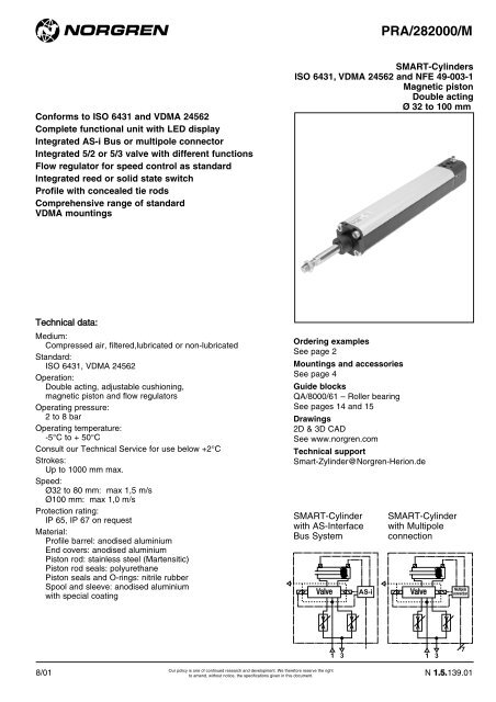
<strong>PRA</strong>/<strong>282000</strong>/MMountings for cylindersA AK B, G C D D2 F∅ Y 7 Page 13 Page 7 Page 7 Page 9 Page 10 Page 832 QM/8032/35 QM/8025/38 QA/8032/22 QA/8032/21 QA/8032/23 QA/8032/42 QM/8025/2540 QM/8032/35 QM/8040/38 QA/8040/22 QA/8040/21 QA/8040/23 QA/8040/42 QM/8040/2550 QM/8050/35 QM/8050/38 QA/8050/22 QA/8050/21 QA/8050/23 QA/8050/42 QM/8050/2563 QM/8050/35 QM/8050/38 QA/8063/22 QA/8063/21 QA/8063/23 QA/8063/42 QM/8050/2580 QM/8080/35 QM/8080/38 QA/8080/22 QA/8080/21 QA/8080/23 QA/8080/42 QM/8080/25100 QM/8080/35 QM/8080/38 QA/8100/22 QA/8100/21 QA/8100/23 QA/8100/42 QM/8080/25FH L M R S SS SW∅ Page 12 Page 9 Page 8 Page 11 Page 12 Page 08 Page 932 QA/8032/34 QA/8032/24 QM/8032/26 QA/8032/27 QA/8032/41 M/P19931 M/P1949340 QA/8040/34 QA/8040/24 QM/8040/26 QA/8040/27 QA/8040/41 M/P19932 M/P1949450 QA/8050/34 QA/8050/24 QM/8050/26 QA/8050/27 QA/8040/41 M/P19933 M/P1949563 QA/8063/34 QA/8063/24 QM/8063/26 QA/8063/27 QA/8063/41 M/P19934 M/P1949680 QA/8080/34 QA/8080/24 QM/8080/26 QA/8080/27 QA/8063/41 M/P19935 M/P19497100 QA/8100/34 QA/8100/24 QM/8100/26 QA/8100/27 QA/8100/41 M/P19936 M/P19498UF UL UR US Guide blocks ## Locking unit #∅ Page 13 Page 10 Page 11 Page 10 Page 14 Page 632 QM/8025/32 QA/8032/43 QA/8032/33 M/P40310 QA/8032/61/* QA/8032/5940 QM/8040/32 QA/8040/43 QA/8040/33 M/P40311 QA/8040/61/* QA/8040/5950 QM/8050/32 QA/8050/43 QA/8050/33 M/P40312 QA/8050/61/* QA/8050/5963 QM/8050/32 QA/8063/43 QA/8063/33 M/P40313 QA/8063/61/* QA/8063/5980 QM/8080/32 QA/8080/43 QA/8080/33 M/P40314 QA/8080/61/* QA/8080/59100 QM/8080/32 QA/8100/43 QA/8100/33 M/P40315 QA/8100/61/* QA/8100/59* Insert standard stroke length (50, 100, 160, 200, 250, 320, 400 or 500) in mm. Consult our Technical <strong>Service</strong> for stroke lengths above 500 mm.# For locking cartridge see page 6; ## For locking cartridge see page 14Accessories for AS-Interface Bus SystemAS-I Power supply for 29,6 V DC AS-I Master controller Software and handbook115/230 V AC → 29,6 V DC (85 W) VE1ASPS1-08519 1 Master (31 Slaves) VE1ASCT1-RS232 VE1ASMA1-G000024 V DC → 29,6 V DC (85 W) VE1ASPS1-08513 2 Master (62 Slaves) VE1ASCT2-RS232115/230 VAC → 29,6 V DC (180 W) VE1ASPS1-18109115/230 VAC → 29,6 V DC + 24 V DC (180 W combined) VE1ASPS3-18019Installation cablesAS-Interface module forfor AS-Interface systems Cable clip external power AS-Interface plug Hand held function Programming cableVE1ASCAY-YMXXX (yellow) VE1ASAC1-CL001 M/P73202 VE1ASCN-M1200 01 020 07 0000 000 00 VE1ASPRG-PCETLVE1ASCAB-YMXXX (black)Full information (technical data, materials, dimensions etc.) please refer to relevant catalogue pages N 6.4.010XXX Insert cable length 25 m = 025, 50 m = 050, 100 m = 100Accessories for multipole connectionY-cableConnector cableM12 female 8 pinHand held function M12 female 8 pin 2 x M12 male 4 pin01 020 07 0000 000 00 M/P73200/2 = 2 m M/P73201 = 0,45 mM/P73200/5 = 5 mM/P73200/10 = 10 mN 1.5.139.04Our policy is one of continued research and development. We therefore reserve the rightto amend, without notice, the specifications given in this document.8/01
<strong>PRA</strong>/<strong>282000</strong>/M<strong>PRA</strong>/<strong>282000</strong>/MG – Cylinders with piston rod bellowsBøAMaximum stroke Piston rod extension B∅ ∅ A per bellow first bellow further bellows32 40 60 30 2540 63 145 50 3250 63 145 40 3263 63 145 40 3280 80 250 50 45100 80 250 50 45<strong>PRA</strong>/<strong>282000</strong>/L4 – Cylinders with locking unit (Passive)ABL 8 + strokeAJSW (A/F)ø ACEEANø B e 11RE1RTAMAOVDADAEAKWHAFAHAGALEØ AB Ø AC AD AE AF AG AH … AJ AK AL AM AN32 32 10 12 8 40 4,2 48 22,7 M 5 16 70,5 840 35,5 10 12 10 46 4,5 55 27,7 M 5 21 74,5 1050 49 15 16 15 54 11,5 70 32,7 M 6 24 91,5 1263 49 15 15 15 55 7,5 70 41 M 8 32 108,5 1280 62 19 16 16 70 10 90 53 M 8 44 141,5 16100 65 19 18 16 70 10 92 53 M 8 60 141,5 16Ø AO Ø B e11 E E 1 EE L 8 … R RT SW (A/F) VD WH Forces *32 4 30 48 50 M 5 94 32,5 M 6 8 10 16 600 N40 4 35 56 58 M 5 105 38 M 6 8 10 18 1000 N50 4 40 68 70 G 1/8 106 46,5 M 8 13 12 22 1500 N63 4 45 82 85 G 1/8 121 56,5 M 8 13 12 20 2200 N80 4 45 100 105 G 1/8 128 72 M 10 17 20 33 5000 N100 4 55 120 130 G 1/8 138 89 M 10 17 23 38 5000 N* Retention forcesSeparate locking cartridgeØ Model Forces *32 QA/8032/63 600 N40 QA/8040/63 1000 N50 QA/8050/63 1500 N63 QA/8063/63 2200 N80 QA/8080/63 3000 N80 QA/8100/63 5000 N* Retention forcesN 1.5.139.06Our policy is one of continued research and development. We therefore reserve the rightto amend, without notice, the specifications given in this document.8/01
<strong>PRA</strong>/<strong>282000</strong>/MQM/8000/25 – Piston rod clevis mounting style ‘F’(Corresponds to DIN ISO 8140)RKCLCMCELECLKKø CK h 11ERQM/8000/26 – Front hinge mounting style ‘M’RKG1CECAø DH 2Lø SG 2K 1K 2G 3M/P199 . . – Bracket for clevis mounting style ‘SS’ø CN G 7EMRG 1ø DCAø SK 1K 2H 2G 2G 3Ø CA CE Ø CK h11 Ø CL CM Ø CN G7 Ø D EM ER G 1 G 2 G 332 32 40 10 20 10 10 11 10 16 21 18 3140 36 48 12 24 12 12 11 12 19 24 22 3550 45 64 16 32 16 16 15 16 25 33 30 4563 50 64 16 32 16 16 15 16 25 37 35 5080 63 80 20 40 20 20 18 20 32 47 40 60100 71 80 20 40 20 20 18 20 32 55 50 70Ø H 2 KK K 1 K 2 L1 LE R RK Ø S ‘F’ ‘M’ ‘SS’32 8 M10x1,25 38 51 1,6 20 10 28 6,6 0,09 kg 0,24 kg 0,15 kg40 10 M12x1,25 41 54 1,6 24 11 32 6,6 0,13 kg 0,33 kg 0,20 kg50 12 M16x1,5 50 65 1,6 32 13 41,5 9 0,33 kg 0,81 kg 0,48 kg63 12 M16x1,5 52 67 1,6 32 15 41,5 9 0,33 kg 0,83 kg 0,50 kg80 14 M20x1,5 66 86 2,5 40 15 50 11 0,67 kg 1,42 kg 0,75 kg100 15 M20x1,5 76 96 2,5 40 19 50 11 0,67 kg 1,87 kg 1,20 kgN 1.5.139.08Our policy is one of continued research and development. We therefore reserve the rightto amend, without notice, the specifications given in this document.8/01
<strong>PRA</strong>/<strong>282000</strong>/MQA/8000/23 – Rear clevis mounting style ‘D’(Corresponds to DIN ISO 6431 and VDMA 24562 Part 2, Style MP2)LH XD + strokeUBCB H 14FLLQA/8000/24 – Rear hinge mounting style ‘L’(Corresponds to VDMA 24562 Part 2)XD + strokeFLG1ø DH2EK f 8MRCAK1K2LHø SG2G3LM/P194 . . – Bracket for clevis mounting (wide clevis) style ‘SW’(Corresponds to VDMA 24562, Part 2)ø CK H 9EMRG 1ø DL 1H 2CAø SK 1K 2G 2G 3Ø CA/CH CB H14 Ø CK H9 Ø D Ø EK f8 EM FL G 1 G 2 G 3 H 2 K 132 32 26 10 11 10 26 22 21 18 31 8 3840 36 28 12 11 12 28 25 24 22 35 10 4150 45 32 12 15 12 32 27 33 30 45 12 5063 50 40 16 15 16 40 32 37 35 50 12 5280 63 50 16 18 16 50 36 47 40 60 14 66100 71 60 20 18 20 60 41 55 50 70 15 76Ø K 2 L L 1 LH MR R Ø S UB XD ‘D’ ‘L’ ‘SW’32 51 1,6 1,6 52 9 10 6,6 45 142 0,11 kg 0,16 kg 0,05 kg40 54 1,6 1,6 60 12 11 6,6 52 160 0,16 kg 0,23 kg 0,07 kg50 65 1,6 1,6 68 12 13 9 60 170 0,22 kg 0,36 kg 0,14 kg63 67 1,6 1,6 79 15 15 9 70 190 0,34 kg 0,52 kg 0,18 kg80 86 2,5 2,5 99 15 15 11 90 210 0,54 kg 0,82 kg 0,28 kg100 96 2,5 2,5 119 20 19 11 110 230 0,90 kg 1,32 kg 0,42 kgOur policy is one of continued research and development. We therefore reserve the right8/01 N 1.5.139.09to amend, without notice, the specifications given in this document.
<strong>PRA</strong>/<strong>282000</strong>/MQA/8000/42 – Rear clevis mounting style ‘D2’(Corresponds to VDMA 24562 Part 2)B2B1 H 14 XD + strokeFLR1R2QA/8000/43 – Universal rear hinge mounting style ‘UL’(Corresponds to VDMA 24562 Part 2)FLG1ø DCHK1K2G2G3LH2B3EK1 h 9ø SM/P403 . . – Bracket hinge for clevis mounting style ‘US’(Corresponds to VDMA 24562 Part 2)ø CN H 7EN -0,1EUZERG 1ZL 1ø DCHH 2ø SK 1K 2G 2G 3Ø B1 H14 B2 B3 CH Ø CN H7 Ø D Ø EK h9 EN -0,1 ER EU FL G 1 G 232 14 34 3,3 32 10 11 10 14 16 10,5 22 21 1840 16 40 4,3 36 12 11 12 16 19 12 25 24 2250 21 45 4,3 45 16 15 16 21 21 15 27 33 3063 21 51 4,3 50 16 15 16 21 24 15 32 37 3580 25 65 4,3 63 20 18 20 25 28 18 36 47 40100 25 75 4,3 71 20 18 20 25 30 18 41 55 50Ø G 3 H 2 K1 K 2 L1 R1 R2 Ø S XD Z ‘D2’ ‘UL’ ‘US’32 31 8 38 51 1,6 11 17 6,6 142 13° 0,20 kg 0,39 kg 0,19 kg40 35 10 41 54 1,6 12 20 6,6 160 13° 0,23 kg 0,47 kg 0,24 kg50 45 12 50 65 1,6 14,5 22 9 170 13° 0,36 kg 0,82 kg 0,46 kg63 50 12 52 67 1,6 18 25 9 190 15° 0,55 kg 1,14 kg 0,59 kg80 60 14 66 86 2,5 22 30 11 210 15° 0,90 kg 1,93 kg 1,03 kg100 70 15 76 96 2,5 22 32 11 230 15° 1,45 kg 2,85 kg 1,40 kgN 1.5.139.10Our policy is one of continued research and development. We therefore reserve the rightto amend, without notice, the specifications given in this document.8/01
Z<strong>PRA</strong>/<strong>282000</strong>/MQA/8000/27 – Rear eye mounting style ‘R’(Corresponds to DIN ISO 6431 and VDMA 24562 Part 2, Style MP4)EWXD + strokeFLL 1QA/8000/33 – Universal rear eye mounting style ‘UR’(Corresponds to VDMA 24562 Part 2)ENXD + strokeFLCN H 7CD H 9MRZR 1ERØ Ø CD H9 Ø CN H7 EN ER EW FL L1 MR R XD Z ‘R’ ‘UR’32 10 10 14 16 25,8 22 13 9 14,5 142 13° 0,09 kg 0,17 kg40 12 12 16 19 27,8 25 16 12 18 160 13° 0,11 kg 0,25 kg50 12 16 21 21 31,7 27 17 12 19 170 13° 0,17 kg 0,40 kg63 16 16 21 24 39,7 32 22 15 24 190 15° 0,24 kg 0,55 kg80 16 20 25 28 49,7 36 22 15 24 210 15° 0,37 kg 0,90 kg100 20 20 25 30 59,7 41 27 20 29 230 15° 0,59 kg 1,50 kg8/01Our policy is one of continued research and development. We therefore reserve the rightto amend, without notice, the specifications given in this document.N 1.5.139.11
<strong>PRA</strong>/<strong>282000</strong>/MQA/8000/34 – Front or rear detachable trunnion mounting style ‘FH’(Corresponds to VDMA 24562 Part 2, Style MT 5/6)L 1RUW 1TD e 9XH L 3XL + strokeTLD H11TM h 14QA/8000/41 – Swivel bearing style ‘S’For trunnion mountings style ‘FH’, ‘UH’ø D 3T 1H 3H7H 1ø D 1F x 45°ø D 2AB 1B 2CØ A B 1 B 2 C Ø D H11 Ø D 1 H7 Ø D 2 Ø D 3 F x 45° H 1 H 3 L 132 32 46 18 10,5 30 12 6,6 11 1 30 15 1640 36 55 21 12 35 16 9 15 1,6 36 18 2050 36 55 21 12 40 16 9 15 1,6 36 18 2463 42 65 23 13 45 20 11 18 1,6 40 20 2480 42 65 23 13 45 20 11 18 1,6 40 20 28100 50 75 28,5 16 55 25 14 20 2 50 25 38Ø L 3 R Ø TD e9 TL TM h14 T 1 UW 1 XH XL ‘FH’ ‘S’32 8 1 12 12 50 6,8 50 18 128 0,20 kg 0,11 kg40 10 1,6 16 16 63 9 55 20 145 0,38 kg 0,16 kg50 12 1,6 16 16 75 9 65 25 155 0,60 kg 0,16 kg63 12 1,6 20 20 90 11 75 25 170 1,10 kg 0,23 kg80 14 1,6 20 20 110 11 100 32 188 1,90 kg 0,23 kg100 19 2 25 25 132 13 120 32 208 3,50 kg 0,42 kgN 1.5.139.12Our policy is one of continued research and development. We therefore reserve the rightto amend, without notice, the specifications given in this document.8/01
<strong>PRA</strong>/<strong>282000</strong>/MQM/8000/38 – Piston rod swivel mounting style ‘AK’SW 3 SW 2 SW 4 SW 14°KKKK4°B 1L 2LFQM/8000/32 – Universal piston rod eye mounting style ‘UF’(Corresponds to DIN ISO 8139)CE 1CN H 7EN -0,1KKZZER 1LE 1AXØ AX B1 CE Ø CN H7 EN -0,1 ER F KK L32 20 5 43 10 14 14 26 M 10 x 1,25 7340 22 6 50 12 16 16 26 M 12 x 1,25 7750 28 8 64 16 21 21 34 M 16 x 1,5 10663 28 8 64 16 21 21 34 M 16 x 1,5 10680 33 10 77 20 25 25 42 M 20 x 1,5 122100 33 10 77 20 25 25 42 M 20 x 1,5 122Ø L 2 LE SW 1 (A/F) SW 2 (A/F) SW 3 (A/F) SW 4 (A/F) Z ‘AK’ ‘F’32 20 15 19 12 17 30 13° 0,20 kg 0,09 kg40 24 17 19 12 19 30 13° 0,20 kg 0,13 kg50 32 22 30 19 24 42 15° 0,65 kg 0,33 kg63 32 22 30 19 24 42 15° 0,65 kg 0,33 kg80 40 26 30 19 30 42 15° 0,72 kg 0,67 kg100 40 26 30 19 30 42 15° 0,72 kg 0,67 kg8/01Our policy is one of continued research and development. We therefore reserve the rightto amend, without notice, the specifications given in this document.N 1.5.139.13
<strong>PRA</strong>/<strong>282000</strong>/MCB +* *CD* *CA + strokeCCCECGDMCF ±0,2CH ø DH H7 x 2,5 deepCKCYDDVI5CO -0,3CPCRCSCJCWDE ±0,2ø DH H7 x 2,5DCDFCX ±0,2CTø DJ2,5 + 0,1-QA/8000/61/* – Guide blocks with roller bearingsdeepø DGSafety zoneø DH* * (28 min) H7CNø DK f6CI* *CHCZCX ±0,22,5ø CV f7DL** Adjustment range*** Centering sleeve**** Safety zone***** Blanking plug (remove when using locking cartridge)Centering sleeveSeparate locking cartridgeDA -0,3DB ±0,3Ø Model Forces *32 QA/8032/63 600 N40 QA/8040/63 1000 N50 QA/8050/63 1500 N63 QA/8063/63 2200 N80 QA/8080/63 3000 N80 QA/8100/63 5000 NBLANKING PLUG(remove when using locking cartridge)* Retention forces per cartridgeØ CA** CB + ** CC CD CE CF ±0,2 CG CH CI** CJ (A/F) CK CN32 177 100 + 5 65 28 12 15,3 6,5 M 6 84,5 13 5 6140 192 111 + 5 69 33 12 23 6,5 M 6 88 15 6 6750 237 128 + 10 65 40 15 33,8 9 M 8 94 22 6 75,563 237 128 + 10 97 40 15 29,3 9 M 8 98,5 22 6 8080 280 151 + 10 112 50 20 37 11 M 10 114 27 7 92100 280 156 + 10 112 55 20 40,5 11 M 10 115,5 27 7 93Ø CO -0,3 CP CR CS CT (A/F) Ø CV f7 CW … CX ±0,2 CY (A/F) CZ DA -0,3 DB ±0,332 97 90 74 50,5 17 12 61 32,5 5 125 50 4540 115 110 87 58,5 19 16 69 38 6 140 58 5450 137 130 104 70,5 24 20 85 46,5 6 150 70 6363 152 145 119 85,5 24 20 100 56,5 6 182 85 8080 189 180 148 105,5 30 25 130 72 8 215 105 100100 213 200 172 130,5 30 25 150 89 8 220 130 120Ø C Ø DD DE ±0,2 DF Ø DG Ø DH H7 DJ Ø DK f6 DL DM at 0 mm per 100 mm32 6,6 11 78 M 6 22,5 9 M 5 9 70,5 14 1,20 kg 0,18 kg40 6,6 11 84 M 6 27,5 9 G 1/8 9 74,5 14 2,20 kg 0,32 kg50 9 15 100 M 8 32,5 11 G 1/8 11 91,5 16 3,60 kg 0,49 kg63 9 15 105 M 8 32,5 11 G 1/8 11 91,5 16 4,60 kg 0,49 kg80 11 18 130 M 10 54,5 13 G 1/8 13 141,5 20 8,70 kg 0,77 kg100 11 18 150 M 10 54,5 13 G 1/8 13 141,5 20 11,0 kg 0,77 kg** Adjustment rangeNote: Supplied complete with mounting screws for cylinders and two centering sleeves.N 1.5.139.14Our policy is one of continued research and development. We therefore reserve the rightto amend, without notice, the specifications given in this document.8/01
<strong>PRA</strong>/<strong>282000</strong>/MMaximum load for QA/8000/61/*Centre of gravityCentre of gravityof load capacityf** Outstroke*** Centre of gravityOutstrokeMaximum load capacity is dependent on the outstroke of ahorizontally installed guide unit. In the case of short strokeoperation, the load capacity figures taken from the diagram mustbe multiplied by the correction factor (diagram 2). In the curves ofload capacity (diagram 1), the short stroke corrections havealready been taken into account for an outstroke > 60 mm.Outstroke* Centre of gravity of load capacity** OutstrokeThe total deflection of guide rods will be determined by the additionof that due to own weight (diagram 3) and that due to load capacity(diagram 4).Maximum load capacity depending on outstroke Deflection caused by own weight Deflection caused by a load of 10 N(diagram 1) (diagram 2) (diagram 3) (diagram 4)Load capacityp yCorrection factor Deflection (mm)( )Deflection (mm)( )( N )ff5001,02,52,5ø 324000,92,02,03000,81,5ø 321,5200100ø 50, 63ø 40ø 32ø 80, 1000,70,61,00,5ø 40ø 50, 63ø 80, 10000,5 000 100 200 300 400 500 6000 20 40 600 100 200 300 400 500 6000 100 200 300 400 500 600O Outstroke t t k (mm) ( )Stroke k (mm) ( )OOutstroke t t k (mm) ( )Outstroke (mm)Reduction of load capacityfor short-stroke operationIn the case of shock load applications, the figures given in the diagrams above must be reduced by a factor of 2.1,00,5ø 40ø 50, 63ø 80, 1008/01Our policy is one of continued research and development. We therefore reserve the rightto amend, without notice, the specifications given in this document.N 1.5.139.15
<strong>PRA</strong>/<strong>282000</strong>/MSpares kits for cylindersØ Model Spares kit32 <strong>PRA</strong>/282032/MI QA/282032/0040 <strong>PRA</strong>/282040/MI QA/282040/0050 <strong>PRA</strong>/282050/MI QA/282050/0063 <strong>PRA</strong>/282063/MI QA/282063/0080 <strong>PRA</strong>/282080/MI QA/282080/00100 <strong>PRA</strong>/282100/MI QA/282100/00WarningThese products are intended for use in industrial compressed airsystems only. Do not use these products where pressures andtemperatures can exceed those listed under ‘Technical Data’.Before using these products with fluids other than those specified,for non-industrial applications, life-support systems, or otherapplications not within published specifications, consult <strong>NOR</strong>GREN.Through misuse, age, or malfunction, components used influid power systems can fail in various modes.The system designer is warned to consider the failure modes of allcomponent parts used in fluid power systems and to provide adequatesafeguards to prevent personal injury or damage to equipment in theevent of such failure.System designers must provide a warning to end users in thesystem instructional manual if protection against a failure modecannot be adequately provided.System designers and end users are cautioned to review specific warningsfound in instruction sheets packed and shipped with these products.N 1.5.139.16Our policy is one of continued research and development. We therefore reserve the rightto amend, without notice, the specifications given in this document.8/01


