TST PowERMAx Installation Instructions - Edge Products
TST PowERMAx Installation Instructions - Edge Products
TST PowERMAx Installation Instructions - Edge Products
- No tags were found...

You also want an ePaper? Increase the reach of your titles
YUMPU automatically turns print PDFs into web optimized ePapers that Google loves.
1998.5-2002 Dodge Cummins 5.9L®<strong>Edge</strong> Comp Module<strong>Installation</strong> <strong>Instructions</strong> & ManualOLD P/N’s: ECD2000, ECD2000A & ECD2000BNEW P/N’s: 30300, 30301, 30301
Table of ContentsDISCLAIMER OF LIABILITY ___________________________________________ 3LIMITATION OF WARRANTY___________________________________________ 3Dodge Cummins 5.9L Comp <strong>Installation</strong> ____________________________________ 7Supplied Items: _____________________________________________________________ 7Items Required: ____________________________________________________________ 7Warranty: _________________________________________________________________ 7Power <strong>Edge</strong> Comp Getting Connected ______________________________________ 8In Cab <strong>Installation</strong> __________________________________________________________ 8MAP Connection ___________________________________________________________ 9Injection Pump Wire Connection ______________________________________________ 9Data Link Connection ______________________________________________________ 11Boost Elbow <strong>Installation</strong> ____________________________________________________ 11Final Inspection and Operation ______________________________________________ 12Power Gains ______________________________________________________________ 13Technical Support _____________________________________________________ 13© 2007, <strong>Edge</strong> <strong>Products</strong>All rights reserved.<strong>Edge</strong> <strong>Products</strong>1080 South Depot Dr.Ogden, UT 84404888-360-3343www.edgeproducts.comManual Version 52<strong>Edge</strong> <strong>Products</strong> Inc.
THIS IS A HIGH PERFORMANCE PRODUCT. USE AT YOUR OWN RISK.DISCLAIMER OF LIABILITYEDGE <strong>Products</strong> Inc. and its distributors, jobbers, and dealers (hereafter SELLER) shall in no way be responsiblefor the product's proper use and service. THE BUYER HEREBY WAIVES ALL LIABILITY CLAIMS.The BUYER acknowledges that he/she is not relying on the SELLER’s skill or judgement to select or furnishgoods suitable for any particular purpose and that there are no liabilities which extend beyond the description onthe face hereof and the BUYER hereby waives all remedies or liabilities, expressed or implied, arising by law orotherwise, (including without any obligations of the SELLER with respect to fitness, merchantability andconsequential damages) or whether or not occasioned by the SELLER's negligence.The BUYER is responsible to fully understand the capability and limitations of his/her vehicle according tomanufacturer specifications and agrees to hold the SELLER harmless from any damage resulting from failure toadhere to such specificationsThe SELLER disclaims any warranty and expressly disclaims any liability for personal injury or damages. TheBUYER acknowledges and agrees that the disclaimer of any liability for personal injury is a material term for thisagreement and the BUYER agrees to indemnify the SELLER and to hold the SELLER harmless from any claimrelated to the item of the equipment purchased. Under no circumstances will the SELLER be liable for anydamages or expenses by reason of use or sale of any such equipment.If the BUYER sends back a failed unit that is out of warranty and chooses to buy a refurbished unit, therefurbished unit will only carry a 60 day warranty. If the BUYER purchases a new unit at a predetermineddiscounted rate, it will have the standard 1 year warranty.The BUYER is responsible to obey all applicable federal, state, and local laws, statutes, and ordinances whenoperating his/her vehicle, and the BUYER agrees to hold SELLER harmless from any violation thereof.The SELLER assumes no liability regarding the improper installation or misapplication of its products.It is the installer's responsibility to check for proper installation and if in doubt, contact the manufacturer.The SELLER recommends that the BUYER temporarily remove this product from his/her vehicle when havingthe vehicle serviced by a dealership or other service facility. Failure to do so may cause erroneous diagnosticreadings or misdiagnosis of vehicle problems. The SELLER assumes no liability for failure to do so.LIMITATION OF WARRANTYEDGE <strong>Products</strong> Inc. (hereafter "SELLER") gives Limited Warranty as to description, quality, merchantability,fitness for any product’s purpose, productiveness, or any other matter of SELLER's product sold herewith. TheSELLER shall be in no way responsible for the product’s open use and service and the BUYER hereby waivesall rights other than those expressly written herein. This Warranty shall not be extended or varied except by awritten instrument signed by SELLER and BUYER.The Warranty is Limited to one (1) year from the date of sale and limited solely to the parts contained within theproduct's kit. All products that are in question of Warranty must be returned shipping prepaid to the SELLER andmust be accompanied by a dated proof of purchase receipt. All Warranty claims are subject to approval byEDGE <strong>Products</strong> Inc.Under no circumstances shall the SELLER be liable for any labor charged or travel time incurred in diagnosis fordefects, removal, or reinstallation of this product, or any other contingent expenses.Under no circumstances will the SELLER be liable for any damage or expenses insured by reason of the use orsale of any such equipment.3<strong>Edge</strong> <strong>Products</strong> Inc.
IN THE EVENT THAT THE BUYER DOES NOT AGREE WITH THIS AGREEMENT: THE BUYER MAYPROMPTLY RETURN THIS PRODUCT, IN A NEW AND UNUSED CONDITION, WITH A DATED PROOF OFPURCHASE, TO THE PLACE OF PURCHASE WITHIN SIXTY (60) DAYS FROM DATE OF PURCHASE FOR AFULL REFUND.THE INSTALLATION OF THIS PRODUCT INDICATES THAT THE BUYERHAS READ AND UNDERSTANDS THIS AGREEMENT AND ACCEPTS I<strong>TST</strong>ERMS AND CONDITIONS.WARNING: The Power <strong>Edge</strong> Comp Module is a high performance product.USE AT YOUR OWN RISK!IT IS HIGHLY RECOMMENDED THAT BOOST AND EGT GAUGES BE USED WITHTHIS PRODUCTIMPORTANT: Read all Disclaimer, Warranty, and <strong>Installation</strong> <strong>Instructions</strong> beforeinstalling product.THIS PRODUCT MUST BE REMOVED WHEN TAKING VEHICLE TO VEHICLE DEALERSHIPOR OTHER SERVICE FACILITY!!LEAVING PRODUCT INSTALLED MAY AFFECT DEALER DIAGNOSTIC ANALYSIS ANDSCAN TOOL FUNCTIONS!!The installation of this product indicates that the BUYER has read and understandsthis agreement as well as the “disclaimer of liability” agreement contained at the end ofthis document and accepts its terms and conditions.Do not use this product until you have carefully read the following agreement.This sets forth the terms and conditions for the use of this product. The installation ofthis product indicates that the BUYER has read and understands this agreement andaccepts its terms and conditions4<strong>Edge</strong> <strong>Products</strong> Inc.
IMPORTANT INFORMATION ABOUT YOUR VEHICLE’SWARRANTY — PLEASE READ!Many of our customers ask, “Will your product void my vehicle’smanufacturer’s warranty?” While the answer is straightforward from alegal standpoint, it’s important to educate our customers (and allafter-market consumers) on some industry realities and offer somecommon sense precautions to minimize your risk.Consumers of aftermarket products are protected by the FederalMagnusson-Moss Warranty Act. The Act states that if somethingbreaks on your vehicle and you take it in for warranty repair, thedealer must honor your warranty unless whatever modifications youhave added to your vehicle actually caused the problem in question.<strong>Edge</strong> is committed to providing quality products that are safe to use.Our products do not cause damage to a vehicle when used asintended. Please keep in mind that towing in anything higher thanlevel two and hard driving in levels four and five are notrecommended. However, the reality is that many dealerships havebeen known to void warranties on vehicles that use aftermarketproducts as a matter of policy. This applies in particular to thoseaftermarket products that produce horsepower, such as performanceenhancement “chips,” modified intake manifolds, or aftermarketexhaust systems, regardless of product brand. Any aftermarketcompany that does not acknowledge this is misleading you.Although you have strong legal protection as a consumer in regard toyour vehicle’s warranty, the practical reality is that taking legal actionagainst a dealer or manufacturer to fight a voided warranty is a costlyand time-intensive process. For this reason, <strong>Edge</strong> stronglyrecommends you always disconnect and remove yourmodule/programmer and monitor when you take your vehicle toa dealer for warranty work. It is also for this reason that <strong>Edge</strong>focuses the bulk of their product development efforts on producingmodules and digital monitors that can be easily removed. Even if youremove your unit, you should note that dealers can detect the use ofANY programmer — Evolution or otherwise — even if the unit hasbeen removed.5<strong>Edge</strong> <strong>Products</strong> Inc.
This warranty is void for any new products purchased through auctionwebsites. Warranty is valid only for new products purchased throughAuthorized Dealers (proof of purchase required for all warrantyclaims).All <strong>Edge</strong> modules and programmers are built to operate with OEM calibrations.When you take your vehicle to a service center they may, by your request orotherwise, update your vehicles calibrations. Therefore it is important that youreturn your vehicle to stock before taking it in for service. <strong>Edge</strong> updates its activeproducts (i.e. those currently being manufactured) to work effectively with updatedOEM calibrations. However, this process can take some time as <strong>Edge</strong> is not alwaysmade aware of calibration changes made by the OEM. In the case of discontinuedproducts, <strong>Edge</strong> cannot ensure that your unit will work effectively if you take yourvehicle to a dealership and you are given, by your request or otherwise, a newcalibration.6<strong>Edge</strong> <strong>Products</strong> Inc.
Dodge Cummins 5.9L Comp <strong>Installation</strong>Supplied Items:1. Power <strong>Edge</strong> Comp Module2. Main Wiring HarnessTo Engine Compartment- Black to Ground; Gray to Fuel InjectionPump; Map Sensor Connection; Data Link Connection.Inside Cab - Red to Fuse Box 12V Power3. Fuel Injection Pump Connector4. Four Wire Ties5. Two Velcro Strips6. One Hose Clamp7. One 90° Brass Fitting8. One Male Spade Fuse ConnectorItems Required:Knife2-3 ft. of wire (fishing)Pliers (needle nose)Phillips ScrewdriverFlat tip Screwdriver3/8” Drive Torque Wrench1/2” Wrench3/8” Drive Ratchet & Sockets1/4” Socket5/16” Socket7/16“ Deep Well Socket andRatchet10 mm Socket13 mm SocketWarranty:1 year Limited Warranty7<strong>Edge</strong> <strong>Products</strong> Inc.
Power <strong>Edge</strong> Comp Getting ConnectedPlease read these instructions and disclaimer through completely andthoroughly understand each step prior to installation.In Cab <strong>Installation</strong>1. Determine a good 12 volt circuit for use as a power source. Verify thiscircuit has power while starting and running and no power with theignition off. NOTE: A good circuit is the number 17 fuse (10 AMPCluster A) inside the fuse panel located on the left side of the instrumentpanel. Remove the fuse panel cover, the number 17 fuse and attach thesupplied male space fuse connector onto the fuse. Reinstall the stockfuse with connector back into the fuse panel (this is a very tight fit).2. Using the ½” wrench, loosen both negative battery cable clamp fasteners,remove cables from the battery posts and set each to the side. NOTE: DONOT reconnect until installation is complete. Connecting power maycause fault code in the ECM, which only an authorized dealer canremove.3. Using the Phillips screwdriver, remove the three screws from the bottomof the knee bolster. Pull the bottom back towards you until it pops loose,remove it and set aside. This gives better firewall access.4. Routing the Supplied Main Wiring Harness. Cut a ¾” slit in thegrommet. Automatics- easy access is the clutch hole grommet located tothe left of the firewall brake hole. Manuals or Automatics- Use the largevehicle wiring harness grommet in the firewall. Fish the supplied harnessthrough the slit from inside the cab out into the engine compartment.Leave about 18” of the supplied wiring harness inside of the cab (white6-wire connector end plus the red wire.)5. Route the supplied red wire up into the fuse panel. Connect the femalespade to the made space fuse connector and reinstall the fuse panel cover.6. Reinstall the knee bolster. Align clips on bolster to holes in lower paneland push. Insert and tighten the three screws in the bottom of the bolster.MAP Sensor8 <strong>Edge</strong> <strong>Products</strong> Inc.
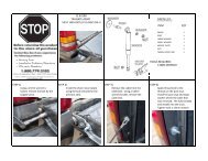
7. Mount the Power <strong>Edge</strong> Comp to your preference. A good location is onthe knee bolster – either side of the steering column. Use the twosupplied Velcro strips.MAP Connection8. Connect the supplied MAP sensorwiring harness to the supplied mainwiring harness in the enginecompartment. Disconnect the stockwiring harness at the boost sensorlocated to the rear of the fuel filterhousing near the top of and on theengine block. Plug the supplied MAPsensor connector into the stock engineboost sensor and the stock enginewiring harness connector into thesupplied MAP sensor connector. TheMAP sensor shown in the image is fora 2001, the 1998.5-2000 are a different sensor but in the same location.Injection Pump Wire Connection9. Using the 13 mm socket, remove the three bolts securing the throttlebracket assembly on top of the Fuel Injection pump. Move it towards thedriver’s side battery.10. Using the 10 mm socket, remove the four bolts securing the air intakeand the bolt securing the oil dipstick tube. Using the 7/16” socket, loosenthe clamp and rotate the air intake assembly counterclockwise to exposethe Fuel Injection Pump stock wiring harness.9 <strong>Edge</strong> <strong>Products</strong> Inc.
11. The stock wiring harness islocated by following it from thecenter of the six fuel supply tubesup to the top rear of the pump.The upper two wires- slide theprotective covering downward toexpose these wires. Install thesupplied pin connector lower halfwith trough onto the wire closestto the engine block; this is the topinner wire. Hold the wire in thistrough while installing the upperhalf of the pin connector onto thelower half. Using the pliers,squeeze the two halves together fully.Pump Wire12. NOTE: Important-while the connector halves are being seated together the wireis not to be rotated. The stock wiring harness that plugs into the injection pumpmay be removed for better access to the wire. Connect the supplied gray wire tothe supplied pin connector wire.13. Reinstall the air intake assembly onto the intake manifold using the fourbolts. Install the ring connector on the supplied black ground wire ontoone of these bolts – preferably the bolt with the large ground wire alreadyattached to it. Using the torque wrench and 10mm socket, torque thesebolts to 18 lb./ft. Install and tighten the oil dipstick tube retaining boltand tighten.14. Reinstall the throttle bracket onto the fuel injection pump using the threebolts. Using the torque wrench and 13mm socket, torque these bolts to18 lb./ft.10 <strong>Edge</strong> <strong>Products</strong> Inc.
Data Link Connection14. The Data Link connector is locatedin different locations based on theyear of the truck:- 98.5-99 the triangle shapedconnector is located on the driversside of the engine in the wiringharness near the power steeringpump- 2000-2001 the three prong flatconnector is located on top of thefuel lift pump that is located on thedriver’s side of the engine directlybelow the MAP sensor, note: onsome 2001 truck’s the connector islocated on the drivers side of theengine in the wiring harness nearthe power steering pumpMAP Sensor& 2000-2002Data Link1998.5-1999 DataLink15. A plug is installed in the data link connector on the truck to resistcorrosion, remove this and install the supplied connector.Boost Elbow <strong>Installation</strong>16. Using the 5/16” socket, loosen the two clamps securing the air inductionhose to the air filter housing and the turbo inlet. Remove the hose and setit aside.17. Using the pliers, remove the crimp style clamp from the hose on the brassfitting located on the now exposed lower front side of the turbocharger.Remove the hose from the brass fitting and dispose of the crimp styleclamp.18. Using the 7/16” wrench, unscrew the stock brass fitting out of theturbocharger housing. Using the 7/16” wrench, install the supplied brassfitting, tighten-be careful not to over-tighten. Slip the supplied hoseclamp onto the stock hose, install the stock hose onto the supplied brassfitting and tighten the hose clamp with the ¼” socket.11 <strong>Edge</strong> <strong>Products</strong> Inc.
19. Reinstall the stock air hose onto the air filter housing and turbochargerinlet. Using the 5/16” socket, tighten both clamps securely.Note: On model year 2001+ with auto transmission, the wastegate is a solidline and does not have a brass elbow to be replaced.Final Inspection and Operation20. Recheck all connections, fittings and fasteners for a properly secureinstallation.21. Using the supplied wire ties, secure the wiring harness from possibledamage.22. Reconnect both negative battery cables onto the battery posts. Using the½” wrench, tighten both fasteners securing the cable clamps to thebattery posts.23. Turn the ignition key on. DO NOT START THE ENGINE! The LEDon the Power <strong>Edge</strong> Comp should light when powered up.24. With the ignition key on, check for the LED on the module. If the LEDis not on, push the gray round button to turn the module on. If the LEDis still not on, check for proper connections – ground and 12 volt power.Do not proceed if the LED does not work as desirable. If the checkengine light appears, proper connections have not been made to the MAPsensor.25. If module does not function as described in Step 23 turn ignition key tothe off position and disconnect both battery ground cables. Check allconnections – pull apart and inspect for bent or broken male. Inspect allstock and supplied connectors thoroughly. If all connectors are good,reconnect insuring each seats tightly. Reconnect battery cables to thebattery posts. Repeat steps 22 and 23. If the problem still exists pleasecall the dealer where purchased for technical assistance.26. To adjust power levels 1-5 on the Power <strong>Edge</strong> Module, push thecorresponding arrow buttons, left arrow will decrease level and rightarrow will increase power level. The levels can be adjusted while theengine is running.12 <strong>Edge</strong> <strong>Products</strong> Inc.
27. Each power level on the Power <strong>Edge</strong> Comp has a submenu that allowsthe user to tune in the low boost fueling to eliminate excess smoke. Toaccess the submenu:a. Be in the power level that you what to adjust the low boost fuelingforb. Press and hold the round gray button (power button) for about 2seconds, release buttonc. The LED’s will be flashing when in the submenud. Use the left and right arrows to adjust the levels 1-5e. When 1 LED is lit this results in the least responsive setting orlowest smoke, all 5 LED’s lit is the most responsivef. Each power level can store a unique submenu settingg. When accessing the submenu for the first time the LED’s mayappear erratically lit, use the right arrow key to light all LED’sthen set to desired level.28. If the Power <strong>Edge</strong> Comp does not function as described above, pleasecall the dealer where purchased.Power GainsThe following power gains are representative of an actual test vehicle.Power gains may vary somewhat on a different vehicle or in differentgeographic settings.Horsepower TorqueLevel 1: 40 150Level 2: 60 200Level 3: 80 250Level 4: 100 300Level 5: 120 350Technical Support888-360-3343To expedite your support call, please have part number (i.e., EAF2100A), versionnumber, and Date of Manufacture ready prior to calling support.13 <strong>Edge</strong> <strong>Products</strong> Inc.