Installation Instructions CKTESTM PETK-10 & PETK-11 - Thermon ...
Installation Instructions CKTESTM PETK-10 & PETK-11 - Thermon ...
Installation Instructions CKTESTM PETK-10 & PETK-11 - Thermon ...
- No tags were found...

You also want an ePaper? Increase the reach of your titles
YUMPU automatically turns print PDFs into web optimized ePapers that Google loves.
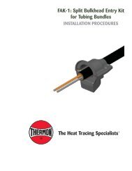
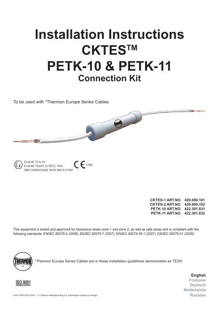
<strong>Installation</strong> <strong>Instructions</strong>CKTES TM<strong>PETK</strong>-<strong>10</strong> & <strong>PETK</strong>-<strong>11</strong>Connection KitTo be used with *<strong>Thermon</strong> Europe Series CablesEx eb IIC T2 to T6Ex tb IIIC T260°C to T85°C IP66SIRA <strong>10</strong>ATEX3368X IECEx SIR<strong>10</strong>.0195X1725CKTES-1 ART.NO. 420.000.<strong>10</strong>1CKTES-2 ART.NO. 420.000.<strong>10</strong>2<strong>PETK</strong>-<strong>10</strong> ART.NO. 422.301.631<strong>PETK</strong>-<strong>11</strong> ART.NO. 422.301.632This equipment is tested and approved for hazardous areas zone 1 and zone 2, as well as safe areas and is compliant with thefollowing standards: EN/IEC 60079-0 (2009), EN/IEC 60079-7 (2007), EN/IEC 60079-30-1 (2007), EN/IEC 60079-31 (2009).*<strong>Thermon</strong> Europe Series Cables are in these installation guidelines denominated as TESH.Form TEP0<strong>10</strong>7U-0512© <strong>Thermon</strong> Manufacturing Co. Information subject to change.EnglishFrançaisDeutschNederlandsRussian
Description 1Connection kit CKTES (Connection Kit <strong>Thermon</strong> Series Cable) is designed to connect a cold lead cable to a seriesconstant watt heating cable or to repair the <strong>Thermon</strong> Europe Series (TESH) constant watt heating cables.The CKTES consists of a non-metallic enclosure which does not need to be earthed. Crimp connectors are used toconnect the braid and the conductor. They are separated by a non-metallic spacer. To make the CKTES watertight asilicone sealant is used to fill the non-metallic body. This body is sealed off on both sides with a grommet and a nonmetallicscrew cap.After installation, the CKTES Termination and in-line splice kit shall be subjected to an insulation resistance testaccording to EN 60079-30-2, clause 8.3.4, using a test voltage of 500 - 2500 Vdc in accordance with local regulations,applied between the live conductors and the metallic braid of the power or heating cables. The measured insulationresistance must be higher than 20 MΩ. For other cold lead cables, contact <strong>Thermon</strong>.Important Remarks And Warnings• Before installing or replacing the product read these instructions completely.• <strong>Thermon</strong> is unable to guarantee the performance of the joint when used in combination with non-<strong>Thermon</strong>products.• <strong>Installation</strong> must comply with local requirements for electric heat tracing systems.• Water and dust ingress must be avoided before, during and after installation, to prevent electrical shock, shortcircuit or arcing.• Due to the risk of electric shock, short circuit, arcing and fire caused by product damage or improper usage,installation or maintenance, <strong>Thermon</strong> heat tracing systems must always be installed in combination with anovercurrent protection device and RCD (Residual Current Device).• Always take into account the markings on the CKTES concerning the temperature classification and explosiongroup.• Modifications to the CKTES are not allowed.• Before installation or replacement of the CKTES, ensure that the power supply to the system is switched off.• For crimping lugs, use standard ratchet action crimping tool. Use crimp connectors matching the conductordiameter. Use crimping tools associated with the crimp connectors.• Avoid skin and eye contact with RTV sealant.• When stored above 5°C, shelf life will be reduced.For Hazardous Areas:• <strong>Installation</strong> must comply with <strong>Thermon</strong> requirements and be installed in accordance with the regulation as perstandard EN/IEC 60079-14 for hazardous areas (where applicable), and/or any other applicable national and localcodes.• This device is not suitable for zone 0. This device can be used in the following ATEX and IECEX zones: zone 1,zone 2, zone 21 and zone 22.• For power termination, use only ATEX/IECeX approved glands, terminals and junction boxes.• <strong>Installation</strong> or replacement of the CKTES in hazardous areas may only be undertaken by qualified personnel withadequate training for the area involved.Form TEP0<strong>10</strong>7U-0512 © <strong>Thermon</strong> Manufacturing Co. Information subject to change.
Kit Contents 2CKTES / <strong>PETK</strong>12Item Quantity Description1 4 PTFE Screw Caps2 2 PTFE Housing3 2 PTFE Spacer4 4 Silicone Rubber Grommet3455 6-<strong>10</strong> Crimp Connectors6 2 Silicone Sealant Tube6Crimp Connectors CKTES-1Item Quantity Description5 2 4 mm² x 15 mm5 4 6 mm² x 15 mm5 2 <strong>10</strong> mm² x 20 mm5 2 16 mm² x 20 mm78 9 <strong>10</strong>Crimp Connectors CKTES-2Item Quantity Description5 2 2,5 mm² x 15 mm5 4 4 mm² x 15 mm<strong>PETK</strong>-<strong>10</strong> (extra items)Item Quantity Description7 1 3 m TESH CL-68 2 Ground Sleeve9 4 Wire Pins for conductor &braiding<strong>PETK</strong>-<strong>11</strong> (extra items)Item Quantity Description7 1 3 m TESH CL-2,58 2 Ground Sleeve9 2 Wire Pins for braiding<strong>10</strong> 2 Wire Pins for conductorTools RequiredForm TEP0<strong>10</strong>7U-0512 © <strong>Thermon</strong> Manufacturing Co. Information subject to change.
Details Of Cold Lead And Lug Sizes 3CKTESKitCKTES-1CKTES-2Cable Type(Ohm/km)In-Line ConnectionCrimp Connector sizeconductor (mm 2 )Crimp Connector sizebraiding (mm 2 )2,9 16 64,4 <strong>10</strong> 67 6 6<strong>10</strong> - 15 4 617,8 - 480 4 4600* - 8000* 2,5 4* Double fold heating cable conductor<strong>PETK</strong>Kits<strong>PETK</strong>-<strong>10</strong><strong>PETK</strong>-<strong>11</strong>Cable Type(Ohm/km)Cold-LeadTypeCold-Lead ConnectionCrimp Connector sizeconductor (mm 2 )Crimp Connector sizebraiding (mm 2 )2,9 CL Not required - -4,4 - 15 CL-6 <strong>10</strong> 617,8 - 480 CL-2,5 4 4600* - 8000* CL-2,5 4 4* Double fold heating cable conductorForm TEP0<strong>10</strong>7U-0512 © <strong>Thermon</strong> Manufacturing Co. Information subject to change.
<strong>Installation</strong> <strong>Instructions</strong> 4Step 1First determine the correct circuit length, then slide the screw cap and therubber grommet over the heating cable and cold lead cable (in case of a powerconnection). Slide the housing over (one of) the heating cable(s).Step 2ItemABCDEFGHIJKLItems drawingsDescriptionHeating CableCold Lead/Heating CableScrew CapSpacerSealantCrimp ConnectorGrommetHousingBraidingConductorOuterjacketPrimary InsulationRemove 60 mm* outer jacket from both cables (*for TESH 600 up to TESH 8000, 75 mm). Separate braid strands atthe end of the outer jacket of the heating cable(s) and cold lead cable (<strong>PETK</strong>-<strong>10</strong>/<strong>11</strong>). Push back the braid away fromthe heating cable to form a pigtail. Remove glass ceramic/polyamide tape. Pull the insulated conductor through theopening in the braid of both cables.Step 3Twist the braid into a pig tail and trim the ends. Cut the braid of the Heating Cable at approximately 30 mm and 50 mmfor the Cold Lead / 2 nd Heating cable. Cut the conductors at 50 mm* and 30 mm* (*for TESH 600 up to 8000, cut 65and 45 mm).Step 4Remove primary insulation of the heating conductor and cold lead over a length of 15 mm (*in case of Cold lead orTESH 2,9 and TESH 4,4 remove 20 mm, for TESH 600 up to 8000 remove 30 mm). **Side view of spacer in image.Form TEP0<strong>10</strong>7U-0512 © <strong>Thermon</strong> Manufacturing Co. Information subject to change.
<strong>Installation</strong> <strong>Instructions</strong> 5Step 5Insert the bare conductor of both the Cold Lead/Heating Cable and Heating Cable into the crimp connector andensure complete overlap of conductors inside the crimp connector. Crimp the crimp connector with matching crimpingtool. Follow the same procedure for terminating the braid of the Cold Lead/Heating Cable and Heating Cable. Forcable type TESH 600 up to TESH 8000, the heating cable conductor shall be folded double within the crimp*. For thecorrect Crimp Connector type, see table page 3.Step 6Place the Spacer between both crimped connectors and ensure that both the leads and crimped connector areproperly placed inside the slots. Put a rich amount of silicone sealant on the crimped connectors and in the slots.*Sealant on Crimp connectors.Step 7Slide the Housing over the assembled connections. Ensure assembled connection is positioned in the centre of theHousing. Fill one end of the Housing with sealant ensuring that there are no air pockets and push the grommet intothe Housing. Ensure the joint and cable ends are held in position. Tighten the screw cap, repeat the operation at theother end. Wipe off excessive sealant.Form TEP0<strong>10</strong>7U-0512 © <strong>Thermon</strong> Manufacturing Co. Information subject to change.
<strong>Installation</strong> <strong>Instructions</strong> 6Step 8Mount the CKTES/<strong>PETK</strong> on a flat surface, with expansion loop of 150 mm in the cables. Heating Cable/Cold Leadsand joint secured in place using fibre fixing tape. Application of tape shall allow a small degree of movement at thejoint and cables to cater for potential expansion and contraction of the pipeline. Do not over-tighten.150 mm150 mmStep 9Do not move the assembled CKTES/<strong>PETK</strong> for minimum 24 hours for complete curing.Form TEP0<strong>10</strong>7U-0512 © <strong>Thermon</strong> Manufacturing Co. Information subject to change.
<strong>Installation</strong> <strong>Instructions</strong> for Power Termination 7DescriptionPower and End Termination Kit <strong>PETK</strong> for <strong>Thermon</strong> TESH series constant watt heating cables in conjunction with<strong>Thermon</strong> JB-K-EX, TED, Terminator ZP-R, ZT-R in hazardous areas. In non-hazardous areas with expediter …/XPPLUS …-IND. See also installation instructions of the relevant heat tracing cable and junction/thermostat enclosures.Step 1Cut and remove cold lead cable overjacket (150 mm).Step 2Separate braid strands at edge of overjacket and pull cable through opening in braid. Twist braid into a pigtail.Trim ends of braid. Remove glass ceramic tape.Form TEP0<strong>10</strong>7U-0512 © <strong>Thermon</strong> Manufacturing Co. Information subject to change.
<strong>Installation</strong> <strong>Instructions</strong> for Power Termination 8Step 3Cut and remove (<strong>10</strong> mm) primary insulation jacket to reveal the bare conductor.Step 4Slide green/yellow ground sleeve over twisted braid. Crimp conductor wire pins on each conductor. Crimp braid wirepin on twisted braid.AddressesEuropean HeadquartersBoezemweg 25 PO Box 2052640 AE Pijnacker The NetherlandsPhone: +31(0)15-3615370Corporate Headquaters<strong>10</strong>0 <strong>Thermon</strong> Dr. PO Box 609San Marcos, TX 78667-0609USAFor the <strong>Thermon</strong> office near you, visit us atWWW.THERMON.COMForm TEP0<strong>10</strong>7U-0512 © <strong>Thermon</strong> Manufacturing Co. Information subject to change.