Colour Exploded Drawings - Ladaniva.co uk
Colour Exploded Drawings - Ladaniva.co uk
Colour Exploded Drawings - Ladaniva.co uk
- No tags were found...

Create successful ePaper yourself
Turn your PDF publications into a flip-book with our unique Google optimized e-Paper software.
ILLUSTRATION ALBUMVAZ - 21213, VAZ - 21214CONTENTSVEHICLE PACKAGING. . . . . . . . . . . . . . . . . . . . . . . . . . . . . . . . . . . . . . . . . . . . . . 2ENGINE (sectional view). . . . . . . . . . . . . . . . . . . . . . . . . . . . . . . . . . . . . . . . . . . . . 3ENGINE (cross-sectional view) . . . . . . . . . . . . . . . . . . . . . . . . . . . . . . . . . . . . . . . . 4Components of crank mechanism and timing gear. . . . . . . . . . . . . . . . . . . . . . . . . . 5ENGINE LUBRICATION SYSTEM. . . . . . . . . . . . . . . . . . . . . . . . . . . . . . . . . . . . . . 6COOLING SYSTEM . . . . . . . . . . . . . . . . . . . . . . . . . . . . . . . . . . . . . . . . . . . . . . . . 7FUEL SYSTEM . . . . . . . . . . . . . . . . . . . . . . . . . . . . . . . . . . . . . . . . . . . . . . . . . . . . 8CARBURETTOR. . . . . . . . . . . . . . . . . . . . . . . . . . . . . . . . . . . . . . . . . . . . . . . . . . . 9CARBURETTOR OPERATION DIAGRAM. . . . . . . . . . . . . . . . . . . . . . . . . . . . . . . 10AIR CLEANER. SILENCERS. . . . . . . . . . . . . . . . . . . . . . . . . . . . . . . . . . . . . . . . . 11CLUTCH . . . . . . . . . . . . . . . . . . . . . . . . . . . . . . . . . . . . . . . . . . . . . . . . . . . . . . . . 12CLUTCH OPERATION SYSTEM. . . . . . . . . . . . . . . . . . . . . . . . . . . . . . . . . . . . . . 13GEARBOX . . . . . . . . . . . . . . . . . . . . . . . . . . . . . . . . . . . . . . . . . . . . . . . . . . . . . . 14GEARBOX OPERATION DIAGRAM . . . . . . . . . . . . . . . . . . . . . . . . . . . . . . . . . . . 15PROPELLER SHAFT . . . . . . . . . . . . . . . . . . . . . . . . . . . . . . . . . . . . . . . . . . . . . . 16TORQUE CONVERTER AND ITS DRIVE SYSTEM. . . . . . . . . . . . . . . . . . . . . . . . 17TORQUE CONVERTER OPERATION DIAGRAM . . . . . . . . . . . . . . . . . . . . . . . . . 18REAR AXLE . . . . . . . . . . . . . . . . . . . . . . . . . . . . . . . . . . . . . . . . . . . . . . . . . . . . . 19FRONT AXLE . . . . . . . . . . . . . . . . . . . . . . . . . . . . . . . . . . . . . . . . . . . . . . . . . . . . 20FRONT SUSPENSION . . . . . . . . . . . . . . . . . . . . . . . . . . . . . . . . . . . . . . . . . . . . . 21REAR SUSPENSION . . . . . . . . . . . . . . . . . . . . . . . . . . . . . . . . . . . . . . . . . . . . . . 22SHOCK ABSORBERS . . . . . . . . . . . . . . . . . . . . . . . . . . . . . . . . . . . . . . . . . . . . . 23STEERING . . . . . . . . . . . . . . . . . . . . . . . . . . . . . . . . . . . . . . . . . . . . . . . . . . . . . . 24BRAKE MECHANISM . . . . . . . . . . . . . . . . . . . . . . . . . . . . . . . . . . . . . . . . . . . . . . 25BRAKE OPERATION DIAGRAM . . . . . . . . . . . . . . . . . . . . . . . . . . . . . . . . . . . . . . 26WIRING DIAGRAM FOR ELECTRICAL EQUIPMENT OF VAZ 21213 VEHICLE. . 27ALTERNATOR . . . . . . . . . . . . . . . . . . . . . . . . . . . . . . . . . . . . . . . . . . . . . . . . . . . 28ALTERNATOR 94.3701 (FOR INJECTION VEHICLES) . . . . . . . . . . . . . . . . . . . . . 29STARTER MOTOR . . . . . . . . . . . . . . . . . . . . . . . . . . . . . . . . . . . . . . . . . . . . . . . . 30IGNITION SYSTEM . . . . . . . . . . . . . . . . . . . . . . . . . . . . . . . . . . . . . . . . . . . . . . . 31WINDSCREEN WIPER . . . . . . . . . . . . . . . . . . . . . . . . . . . . . . . . . . . . . . . . . . . . . 32BODY . . . . . . . . . . . . . . . . . . . . . . . . . . . . . . . . . . . . . . . . . . . . . . . . . . . . . . . . . . 33BODY FITTINGS. . . . . . . . . . . . . . . . . . . . . . . . . . . . . . . . . . . . . . . . . . . . . . . . . . 34HEATING AND VENTILATION. WIPER/WASHER. . . . . . . . . . . . . . . . . . . . . . . . . 35INJECTION SYSTEM (GM). . . . . . . . . . . . . . . . . . . . . . . . . . . . . . . . . . . . . . . . . . 36INJECTION SYSTEM DIAGRAM (GM) . . . . . . . . . . . . . . . . . . . . . . . . . . . . . . . . . 37WIRING DIAGRAM FOR INJECTION SYSTEM (GM) . . . . . . . . . . . . . . . . . . . . . . 38WIRING DIAGRAM FOR INJECTION SYSTEMEURO2. . . . . . . . . . . . . . . . . . . . . 39WIRING DIAGRAM FOR INJECTION SYSTEM EURO3 . . . . . . . . . . . . . . . . . . . . 40TOGLIATTI • RUSSIA • AO AVTOVAZ2001
2VEHICLE PACKAGINGSpecificationPayload, kg . . . . . . . . . . . . . . . . . . . . . . . 400Kerbweight , kg . . . . . . . . . . . . . . . . . . . 1210Max. speed, km/h . . . . . . . . . . . . . . . . . . 137Acceleration time from 0 to 100 km/h,with gearchange, on GVW vehicle, sec . . 21Overall dimensions, mm:length . . . . . . . . . . . . . . . . . . . . . . . . 3740width . . . . . . . . . . . . . . . . . . . . . . . . 1680unladen height . . . . . . . . . . . . . . . . . 1640Wheelbase, mm. . . . . . . . . . . . . . . . . . . 2200Track:front, mm . . . . . . . . . . . . . . . . . . . . . 1430rear, mm . . . . . . . . . . . . . . . . . . . . . . 14001. Headlight2. Front lamp3. Jack4. Radiator4. Windscreen / headlight washer fluid reservoir6. Engine7. Air cleaner8. Cooling system expansion tank9. Battery10. Differential lock lever in transfer box11. Gear change lever12. Gear change lever in transfer box13. Steering wheel14. Front seat15. Rear seat16. Tailgate washer fluid reservoir17. Main silencer18. Rear bumper19. Rear brakes20. Rear suspension <strong>co</strong>il spring21. Rear shock - absorber22. Rear suspension transverse torque rod23. Rear suspension longitudinal torque rod24. Fuel tank25. Rear axle26. Intermediate silencer27. Rear propeller shaft28. Reservoir for brake hydraulic fluid29. Reservoir for clutch hydraulic fluid30. Torque <strong>co</strong>nverter31. Clutch pedal32. Brake pedal33. Front brake34. Front suspension <strong>co</strong>il spring35. Front axle36. Direction indicator side repeater light37. Front bumper
ENGINE(sectional longitudinal view)SpecificationEngine model . . . . . . . . . . . . . . . VAZ - 21213Cylinder bore and piston stroke, mm. 80 x 80Displacement, l . . . . . . . . . . . . . . . . . . . . 1.69Compression ratio . . . . . . . . . . . . . . . . . . . 9.3Rated power as per GOST 14846-89 (net)and ISO 1585-82 at crankshaft rate5,200 rpm, kW (HP) . . . . . . . . . . . . . . 59 (80.2)1. Crankshaft2. Main bearing shell3. Crankshaft sprocket4. Crankshaft front oil seal5. Crankshaft pulley6. Ratchet7. Timing <strong>co</strong>ver8. Coolant pump / alternator drivebelt9. Alternator pulley10. Oil pump / ignition distributor / fuel tank /drive sprocket11. Oil pump / ignition distributor / fuel tankdrive shaft12. Engine <strong>co</strong>oling system fan13. Cylinder block14. Cylinder head15. Timing chain16. Camshaft sprocket17. Exhaust valve18. Inlet valve19. Camshaft bearing housing20. Camshaft21. Valve operating lever22. Valve <strong>co</strong>ver23. Coolant temperature gauge sender24. Spark plug25. Piston26. Gudgeon pin27. Crankshaft rear oil seal retainer28. Crankshaft thrust half-ring29. Flywheel30. Upper <strong>co</strong>mpression ring31. Lower <strong>co</strong>mpression ring32. Oil ring33. Clutch bellhousing <strong>co</strong>ver plate34. Oil sump35. Power unit front mounting36. Connecting rod37. Front mounting bracket38. Power unit39. Power unit rear mounting3
4ENGINE(cross-sectional view)1. Big end cap2. Shell bearing3. Connecting rod4. Starter motor5. Starter motor heat shield6. Exhaust manifold7. Inlet pipe drain tube8. Inlet pipe9. Oil deflector cap10.Valve <strong>co</strong>llet11. Valve spring cap12. Valve operating lever spring13. Valve operating lever14. Valve adjuster bolt15. Ignition distributor16. Adjuster bolt bush17. Valve guide18. Valve seat19. Oil pump / ignition distributor / fuel pumpdrive shaft20. Fuel pump21. Oil pump / ignition distributor drive gear22. Oil filter23. Oil pump drive shaft24. Oil pump body25. Oil pump driven gear shaft26. Oil pump drive gear27. Oil pump <strong>co</strong>ver28. Reducing valve spring29. Reducing valve30. Oil pump driven gear31. Oil pump inlet pipe32. Camshaft sprocket33. Chain damper34. Oil pump / ignition distributor / fuel pumpdrive sprocket35. Valve chain36. Crankshaft sprocket37. Chain stop pin38. Chain tensioner shoe39. Chain tensionerA. Mounting lug on camshaft bearing housingB. Camshaft sprocket timing markC. Cylinder block timing markD. Timing mark on crankshaft sprocketE. TDC pointer on crankshaft pulleyF. 0 0 timing markG. 5 0 timing markH. 10 0 timing markI. Firing ordera. Inductionb. Compressionc. Powerd. Exhaust
ëOMPONENTS OF CRANKMECHANISM AND TIMING GEAR1. Tensioner housing2. Cap nut3. Tensioner rod4. Circlip5. Clamping block6. Plunger7. Spring, tensioner8. Washer9. Spring, plunger10. Camshaft sprocket11. Thrust flange12. Camshaft bearing housing13. Camshaft14. Big-end bearing shells15. Big end cap16. Connecting rod17. Bush, <strong>co</strong>nrod small end18. Circlip19. Piston20. Top <strong>co</strong>mpression ring21. Bottom <strong>co</strong>mpression ring22. Oil ring23. Gudgeon pin24. Thermoregulator plate25. Bolt, <strong>co</strong>nrod26. Starter ring gear27. Flywheel28. Thrust half-ring, rear29. Front bearing, gearbox input shaft30. Thrust half-ring, front31. Centre main bearing (No 3) shells32. Crankshaft oil gallery plug á33. 1st, 2nd, 4th and 5th crankshaft bearing shells34. Crankshaft35. Crankshaft sprocket36. Alternator drive / <strong>co</strong>olant pump pulley37. Nut38. Inlet valve39. Inlet valve guide40. Exhaust valve guide41. Exhaust valve42. Seat, outer spring43. Seat, inner spring44. Inner valve spring45. Outer valve spring46. Spring seat47. Valve <strong>co</strong>llet48. Outer cap49. Circlip50. Washer, adjusting bolt51. Locknut52. Spring53. Push rod54. Stop plate, push rod spring55. Adjusting bolt, valvea, b, c – TDC marks, 1st and 4th cylinder pistons5
6ENGINE LUBRICATION SYSTEM1. Sprocket hole for chain lubrication2. Camshaft main oil gallery3. Cam lobe oilway4. Camshaft centre bearing journal oil recess5. Oil filler neck6. Camshaft journal oilway7. Inclined oilway in cylinder head8. Oilway to timing gear9. Cylinder block main oil gallery10. Oil pressure warning light sender11. Oilway to main bearing12. Oilway to big end bearing13. Oil sump14. Oil filter15. By-pass valve16. Paper filter element17. Check valve18. Oil pump19. Oil pump - to - oil filter gallery20. Oilway from oil filter to main oil gallery21. Oilway to oil pump drive gear bush22. Front crankshaft grease seal23. Oilway to main bearing and to oil pump drive gearshaft24. Oil pump / ignition distributor drive shaft25. Inlet pipe26. Throttle valve, carburettor se<strong>co</strong>ndary barrel27. Throttle valve, carburettor primary barrel28. Air cleaner unit29. Discharge ventilation manifold30. Flame arrester31. Hose to draw crankcase gases behind carburettorthrottle valve32. Discharge hose33. Oil level dipstick34. Oil separator <strong>co</strong>ver35. Oil separator36. Drain pipeI. Engine crankcase ventilation diagram
COOLING SYSTEM1. Temperature sensor for fuel injection system2. Radiator top hose3. Expansion tank filler cap4. Expansion tank5. Radiator cap6. Fluid return hose to expansion tank7. Cooling water jacket8. Filler neck9. Inlet valve10. Exhaust (steam) valve11. LH fluid <strong>co</strong>oler12. Radiator matrix13. RH fluid <strong>co</strong>oler14. Fan impeller15. Swirler16. Radiator mounting rubber17. Fan <strong>co</strong>wl18. Fan belt19. Radiator outlet hose20. Coolant pump21. Coolant pump supply hose22. Thermostat23. Thermostat by-pass hose24. Coolant return hose from heater radiator25. Coolant return pipe from part throttlechannel heater26. Coolant supply hose to part throttle channelheater27. Coolant return hose from heater radiator28. Coolant supply hose to heater radiator29. Rubber insert30. Inlet elbow (from radiator)31. Main valve32. Thermostat housing33. By-pass valve34. By-pass hose pipe35. Coolant pump supply pipe36. Thermostat <strong>co</strong>ver37. Piston38. Water pump <strong>co</strong>ver39. Oil seal thrust sealing ring40. Oil seal <strong>co</strong>llar41. Water pump shaft bearing outer ring42. Fan pulley hub43. Stop screw44. Water pump shaft45. Water pump housing46. Water pump impeller47. Inlet pipeI. Thermostat operation diagramA. Coolant temperature below 80 0 CB. Coolant temperature within 80 to 94 0 CC. Coolant temperature over 94 0 C.7
8FUEL SYSTEM1. Rocker arm shaft2. Rocker arm3. Pushrod4. Bottom <strong>co</strong>ver5. Delivery valve6. Delivery union7. Suction valve8. Fuel filter9. Suction union10. Fuel pump eccentric on shaft 19 (See p.4)11. Thermal insulating spacer12. Gasket13. Fuel tank shim14. Priming lever15. Rocker16. Eccentric17. Fuel tank <strong>co</strong>ver18. Diaphragm plate19. Inner spacer20. Upper diaphragms21. Lower diaphragm22. Outer spacer23. Return spring24. Pullrod25. Top <strong>co</strong>ver26. Carburettor27. Fuel pump28. Fine filter29. Check valve30. Return flow line31. Supply line from fuel tank32. Intake pipe filter33. Fuel gauge sender34. Fuel tank35. Fuel vapour separator36. Separator <strong>co</strong>nnecting hoses37. Air hose38. Fuel filler neck39. Filler cap40. Vent hoseI. Fuel pump operation diagramII. Fuel pump mounting diagram
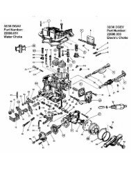
CARBURETTOR1. Part throttle channel heater2. Primary throttle3. Crankcase emission suction union4. Accelerator pump operating lever5. Accelerator pump rocker arm6. Accelerator pump diaphragm7. Fuel jet, part throttle enrichment8. Ball valve, part throttle enrichment9. Diaphragm, part throttle enrichment10. Electromagnetic shut-off valve11. Idling fuel jet12. Return pipe to fuel tank13. Carburettor <strong>co</strong>ver14. Supply union15. Primary barrel main air jet16. Choke valve plate17. Accelerator pump atomizers18. Pull-down diaphragm19. Adjustment screw20. Throttle stop screw21.22. Vacuum discharge to EGR system23. Vacuum discharge to ignition distributor vacuum <strong>co</strong>ntrol24. Idle mixture adjusting screw25. Primary throttle adjustment screw (pull-down unit)26. Choke operating lever27. Choke drive lever28. Se<strong>co</strong>ndary barrel main air jet29. Emulsion tube30 Se<strong>co</strong>ndary barrel main fuel atomizer31. Fuel filter32. Float chamber needle valve33. Carburettor body34. Se<strong>co</strong>ndary throttle35. Se<strong>co</strong>ndary throttle lever36. Se<strong>co</strong>ndary barrel main fuel jet37. Se<strong>co</strong>ndary throttle operating lever38. Float39. Throttle valves operating lever40. Se<strong>co</strong>ndary barrel lock lever9
10CARBURETTOR OPERATION DIAGRAM1. Adjustment screw (choke pull-down unit)2. Pull-down diaphragm3. Pushrod4. Electromagnetic shut-off valve5. Idling fuel jet6. Main air jet, primary barrel7. Idling air jet8. Main fuel atomizer, primary barrel9. Choke valve plate10. Accelerator pump nozzle11. Main fuel atomizer, se<strong>co</strong>ndary barrel12. Injection pipe, full throttle enrichment13. Se<strong>co</strong>ndary main air jet14. Air <strong>co</strong>rrection jet, se<strong>co</strong>ndary barrel15. Carburettor top <strong>co</strong>ver16. Needle valve17. Return line to fuel tank18. Fuel-to-tank return jet19. Fuel filter20. Fuel supply to carburettor21. Diaphragm, part throttle enrichment22. Ball valve, part throttle enrichment23. Fuel jet, part throttle enrichment24. Float25. Fuel jet and tube, full throttle enrichment26. Se<strong>co</strong>ndary barrel fuel <strong>co</strong>rrection jet with tube27. Se<strong>co</strong>ndary barrel emulsion tube28. Se<strong>co</strong>ndary barrel main fuel jet29. Se<strong>co</strong>ndary throttle30. Primary throttle31. Part throttle channel heater32. Idle mixture adjustment screw33. Crankcase emission discharge pipe34. Vacuum discharge to ignition distributor vacuum<strong>co</strong>ntrol35. Vacuum discharge to EGR valve (se<strong>co</strong>nd pipe is notshown)36. Primary main fuel jet37. Primary emulsion tube38. Accelerator pump non-return ball valve39. Accelerator pump diaphragm40. Accelerator pump operating lever41. Choke drive lever42. Outer rod securing bracket43. Primary throttle adjusting screw (pull-down unit)44. Throttle valve operating lever45. Choke <strong>co</strong>ntrol lever46. Fuel supply ball valve47. Accelerator pump operating cama. Air passage, pull-down unitb. Float chamber balance passagec. Air passage, part throttle enrichmentd. Fuel passage, part throttle enrichmente. Se<strong>co</strong>ndary <strong>co</strong>rrection outlet portsf. Idling air passage holeg. Idling transients holeI. Carburettor operation diagram at full throttleII. Pull-down unit operation diagramIII. Carburettor operation diagram at idle speedIY. Carburettor operation diagram at part throttleV. Acceleration pump operation diagram
AIR CLEANER. SILENCERS.1. EGR valve thermo-vacuum switch2. Exhaust manifold3. EGR valve4. EGR tube5. Intake manifold6. Carburettor7. Cold air intake8. Temperature flap9. Warm air intake manifold10. Pinch bolt11. Air cleaner housing12. Pointer for air filter <strong>co</strong>ver alignment13. Gauze14. Filter element perforated plates15. Paper filter element16. Air cleaner <strong>co</strong>ver mounting bracket17. Securing nut18. Discharge pipe19. Air cleaner <strong>co</strong>ver20. Front exhaust pipe21. Front exhaust pipe bracket22. Clips23. Intermediate silencer24. Suspension rings25. Main silencer26. Tail pipe27. Intermediate silencer rear perforated tube28. Intermediate silencer rear baffle plate29. Front baffle plate30. Front perforated tube31. Intermediate silencer housing32. Main silencer front perforated tube33. Main silencer inlet pipe34. Main silencer outlet pipe35. Main silencer housing36. Rear baffle plate37. Centre baffle plate38. Rear perforated tube39. Front baffle plateI. Recirculation diagramII. Air cleaner unitIII. Intermediate silencerIY. Main silencer11
12CLUTCH1. Diaphragm spring2. Clutch friction discs3. Diaphragm spring rivet4. Clutch disc5. Rivet - damper tip6. Disc adaptor7. Retainer plate8. Clutch disc hub9. Damper spring10. Pressure plate11. Flywheel12. Clutch <strong>co</strong>ver13. Clutch bellhousing14. Gearbox input shaft15. Pressure plate - to - clutch <strong>co</strong>ver strap16. Diaphragm spring clip17. Diaphragm spring fulcrum ring18. Thrust flange / clutch <strong>co</strong>ver strap19. Thrust flange friction washer20. Strap rivet21. Diaphragm spring thrust flange22. Release bearing23.Clutch release fork / bearing spring24. Clutch release bearing25. Damper friction washer26. Spring washer bearing disc27. Damper spring washer28. Release fork ball pivot29. Release fork spring30. Release fork pushrod31. Clutch release fork32. Slave cylinder33. Release fork return springI. Damper operation diagram
CLUTCH OPERATION SYSTEM1. Clutch master cylinder2. Vacuum servo unit3. Brake master cylinder4. Servo boot5. Vacuum servo bracket6. Pedal cluster mounting bracket7. Over-centre spring hook8. Pedal spacer sleeve9. Pedal outer bushes10.Brake / clutch pedal shaft11. Pedal inner bush12. Brake pedal return spring13. Booster spring14. Master cylinder fluid reservoir15. Filler cap16. Baffle17. Clutch <strong>co</strong>ver18. Clutch disc19. Pressure plate20. Diaphragm spring21. Clutch release bearing22. Gearbox input shaft23. Bleed nipple24. Sealing ring25. Slave cylinder housing26. Protective cap27. Release fork pushrod28. Piston29. Piston bearing plate30. Spring disc31. Circlip32. Plug33. Clutch release fork ball pivot34. Clutch release fork35. Adjustment nut36. Locknut37. Clutch pedal return spring38. Brake pedal39. Clutch pedal screw40. Clutch pedal41. Union42. Retaining washer43. Gasket44. Circlip45. Pushrod piston46. Master cylinder piston47. Return spring48. Master cylinder bodyI. Clutch hydraulic system operation diagram13
14GEARBOX1. Input shaft2. Gearbox front <strong>co</strong>ver with clutch releasebearing guide sleeve3. Input shaft oil seal4. Spring washer5. Bearing thrust ring6. Gearbox housing7. Breather8. Output shaft needle bearing9. Synchro sleeve thrust washer10. 4th speed synchro unit crown11. 3rd / 4th synchro unit sleeve12. 3rd / 4th synchro unit hub13. Circlip14. Synchro - ring15. Spring16. 3rd speed synchro gear17. 2nd speed synchro gear18. Output shaft19. 1st speed synchro gear20. 1st gear bush21. Output shaft idler bearing22. Lock plate23. Flange24. Bellows25. Spring26. Gear change lever27. Lever rod28. Thrust ring29. Rubber ring30. Spacer31. Retaining sleeve32. Collar33. Cap34. Ball socket35. Gear change lever housing36. Guide plate37. Propeller shaft <strong>co</strong>upling flange38. Nut39. Centering ring seal40. Centering ring41. Output shaft rear bearing oil seal42. Output shaft rear bearing43. Spacer sleeve44. Oil deflector washer45. Gear unit bearing46. 5th speed / reverse gear unit47. Reverse idler gear shaft48. Reverse idler gear49. Intermediate shaft rear bearing50. Intermediate shaft 1st speed gear51. 1st/2nd synchro sleeve52. Intermediate shaft 2nd speed gear53. Intermediate shaft 3rd speed gear54. Filler and check orifice cap55. Intermediate shaft56. Intermediate shaft <strong>co</strong>nstant mesh gear57. Intermediate shaft front bearing58. Intermediate shaft bearing clamping washer59. Clamping washer bolt60. Input shaft <strong>co</strong>nstant mesh gear61. Input shaft rear bearing62. Circlip63. Reverse lock clip64. Guide plate washers65. Guide bar66. Detents <strong>co</strong>ver67. Spring68. Detent69. 5th / reverse shift fork70. Thrust washer71. Circlip72. 3rd / 4th selector fork73. 1st / 2nd selector rod74. 3rd / 4th selector rod75. 1st / 2nd selector fork76. 5th / reverse selector rod77. Locking <strong>co</strong>llets
GEARBOX OPERATION DIAGRAM1. Input shaft2. Output shaft3. Input shaft <strong>co</strong>nstant mesh gear4. 4th speed synchro crown5. 4th gear synchro baulk ring6. 3rd and 4th synchro sleeve7. 3rd and 4th gear selector fork8. Synchro circlip9. 3rd synchro baulk ring10. Synchro spring11. Synchro spring thrust washer12. 3rd synchro gear and crown13. 2nd synchro gear and crown14. 1st and 2nd synchro sleeve15. 1st and 2nd gear selector fork16. 1st synchro gear and crown17. Reverse gear18. 5th synchro sleeve hub19. 5th synchro sleeve20. 5th and reverse gear selector fork21. Gear change lever22. 5th synchro gear and crown23. Oil deflector washer24. 5th gear bush25. Distance sleeve26. Flexible sleeve flange27. 5th gear and reverse selector rod28. 3rd and 4th selector rod29. 1st and 2nd selector fork rod30. Reverse light switch31. Gear unit reverse gear32. Reverse idler gear33. End plug34. 5th and reverse gear unit35. Reverse idler gear shaft36. Layshaft 1st speed gear37.1st synchro baulk ring38. 1st and 2nd synchro sleeve hub39. 2nd synchro baulk ring40. Layshaft 2nd speed gear41. Layshaft 3rd speed gear42. 3rd and 4th synchro sleeve hub43. Layshaft <strong>co</strong>nstant mesh gear44. Circlip45. Poppet springI. Neutral positionII. Beginning of 3rd gear engagementIII. Complete engagement of 3rd gear15
16PROPELLER SHAFT1. LH wheel drive2. Front axle3. RH wheel drive4. Forward propeller shaft5. Gearbox6. Engine7. Layshaft flexible <strong>co</strong>upling8. Layshaft <strong>co</strong>nstant velocity joint9. Torque <strong>co</strong>nverter10. Rear propeller shaft11. Rear axle12. Sliding yoke13. Oiler14. Retainer15. Grease seal16. Propeller shaft end17. Propeller shaft tube18. Balance plate19. Propeller shaft joint fork20. Propeller shaft trunnion21. Needle bearing circlip22. Needle roller housing23. Flange - propeller shaft yoke24. Washer25. Needle roller26. Needle bearing oil seal27. Trunnion oil seal28. Constant velocity joint shell29. Ball30. Boot31. Protective shroud32. Cage33. Coupling flange securing bolt34. Coupling flange35. Coupling liner36. Balance washer37. Rubber sleeve38. Centering bush39. Clips40. Plug41. Oil seal splash guard ring42. Outer joint shell43. Circlip44. Outer joint race45. Thrust ring46. Outer joint boot47. Protective sleeve48. Road wheel drive shaft49. Inner joint boot50. Detent51. Inner joint race52. Inner joint shellI. Drive line viewII. Front wheel drive
TORQUE CONVERTER ANDITS DRIVE SYSTEM1. Driven gear2. Differential bearings3. Spring washer4. Circlip5. Differential locking <strong>co</strong>upling6. Differential carrier crown7. Front axle drive shaft crown8. Front axle drive shaft bearing9. Oil slinger10. Splash guard11. Front axle drive shaft12. Flange13. Oil seal14. Oil drain plug15. Speedometer driven gear16. Speedometer drive gear17. Plug, oil level inspection / top-up orifice18. Torque <strong>co</strong>nverter front <strong>co</strong>ver19. Layshaft roller bearing20. Bracket, torque <strong>co</strong>nverter mount21. Input shaft bearing <strong>co</strong>ver22. Bearing thrust ring23. Input shaft bearings24. Top gear25. Gear shift clutch hub26. Gear shift clutch27. Torque <strong>co</strong>nverter casing28. Low gear29. Low gear bush30. Input shaft31. Rear <strong>co</strong>ver32. Layshaft ball bearing33. Layshaft34. Differential housing35. Rear axle differential gear thrust washer36. Rear axle drive shaft bearing37. Rear axle differential gear38. Pinion39. Pinion thrust washer40. Circlip41. Pinion shaft42. Spring washer43. Front axle differential gear44. Suspension mounting bracket rubber45. Shaft, torque <strong>co</strong>nverter mount46. Differential locking clutch yoke47. Yoke stop bolt48. Locked differential warning light switch49. Boot50. Spring51. Differential locking fork rod52. Front axle case <strong>co</strong>ver53. Lock washer54. Lever shaft bush55. Lever shaft56. Differential locking lever57. Gear shift fork rod58. Gear lever bracket59. Gear lever60. Gear lever knob61. Gear shift clutch fork62. Spacer sleeve63. Detent ball64. Detent spring bush65. Detent springI. Torque <strong>co</strong>nverter operating system17
18TORQUE CONVERTER OPERATIONDIAGRAM1. Grease seal2. Thrust ring, input shaft front bearing3. Front bearing <strong>co</strong>ver4. Input shaft front bearing5. Torque <strong>co</strong>nverter front <strong>co</strong>ver6. Top gear7. Gear engagement clutch hub8. Gear engagement clutch9. Low gear10.Torque <strong>co</strong>nverter case11. Input shaft rear bearing12. Input shaft13. Torque <strong>co</strong>nverter rear <strong>co</strong>ver14. Layshaft15. Layshaft rear bearing16. Differential rear bearing17. Rear axle drive shaft retaining ring18. Rear axle drive shaft bearing19. Oil slinger20. Rear axle drive shaft flange21. Rear axle drive shaft22. Bearing thrust ring23. Differential housing24. Rear axle drive gear25. Pinion26. Differential pinion shaft27. Differential pinion shaft circlip28. Spring washer29. Driven gear30. Differential front bearing circlip31. Differential lock <strong>co</strong>upling32. Front axle drive shaft33. Front axle casing34. Circlip, front axle drive shaft bearing35. Differential front bearing spring washer36. Differential front bearing37. Speedometer driven gear38. Speedometer drive unit housing39. Layshaft front bearing40. Gearbox41. Coupling42. CV joint43.Torque <strong>co</strong>nverter44. Shims45. Bracket, torque <strong>co</strong>nverter mounting46. Bracket, engine rear mountingI. Top gear engagedII. Low gear engagedIII. Low gear engaged, differential locked up
VAZ - 21213REAR AXLE1. Road wheel cap2. Brake drum - to - wheel securing bolt3. Oil deflector4. Brake drum5. Brake drum iron ring6. Wheel cylinder7. Brake bleed nipple8. Half-shaft bearing9. Bearing locking <strong>co</strong>llar10. Rear axle beam flange11. Half-shaft oil seal12. Coil spring cup13. Rear axle beam14. Suspension bar securing bracket15. Half-shaft guide16. Differential bearing nut17. Differential bearing18. Differential bearing <strong>co</strong>ver19. Breather20. Pinion21. Crown wheel22. LH halfshaft23. Halfshaft gear24. Rear axle reduction gear casing25. Drive gear shim26. Bearing spacer sleeve27. Bearing, pinion28. Oil seal, pinion29. Oil seal splash guard30. Propeller shaft securing flange31. Nut32. Oil baffle33. Pinion, final drive34. Differential pinion shaft35. Half-shaft gear thrust wsher36. Differential case37. RH halfshaft38. Bracket to secure suspension <strong>co</strong>mponents39. Thrust plate, half-shaft bearing40. Rear brake backplate41. Rear brake shoe42. Friction disc43. Half-shaft flange44. Bearing nut lockplate45. Bearing <strong>co</strong>ver securing bolt19
20FRONT AXLE1. Differential case2. Differential pinion3. Differential pinion shaft4. Half-shaft gear5. Crown wheel6. Bearing <strong>co</strong>ver retaining stud7. Front axle casing8. Drain plug9. Casing lower <strong>co</strong>ver10. Casing <strong>co</strong>ver11. Bracket, engine front mounting12. Front axle securing stud13. Front axle securing bracket, LH14. Pinion bearings15. Pinion, final drive16. Spacer sleeve17. Pinion oil seal18. Oil seal splash guard19. Pinion flange20. Flange securing nut21. Road wheel drive inner joint22. Inner joint bearing23. Bearing locating ring24. Spring washer25. Circlip26. Differential bearing adjuster nut27. Differential bearing28. Inner joint shell, RH halfshaft29. Breather30. RH bracket, front axle31. Drive gear shim32. Bearing oil deflector33. Half-shaft gear thrust washer34. Filler plug35. LH half-shaft, inner joint shell36. Inner joint shell bearing <strong>co</strong>ver37. Splash guard, joint shell oil seal38. Oil seal39. Differential bearing <strong>co</strong>ver40. Adjuster nut lockplate
FRONT SUSPENSION1. Lower <strong>co</strong>ntrol arm2. Crossmember bracket3. Coil spring lower seat4. Coil spring5. Compression buffer6. Compression buffer mount strut7. Compression restrictor8. Shock absorber mounting bracket9. Shock absorber10. Anti-roll bar securing clamp11. Anti-roll bar mounting rubber12. Anti-roll bar13. Lower balljoint14. Wheel brake splash guard15. Brake disc16. Wheel hub17. Wheel - to - brake disc securing bolt18. Taper bush19. Wheel cap20. Outer CV joint shank21. Oil seal bush22. Oil seal23. Splash guard ring24. Wheel hub bearing25. Stub axle26. Ballpin27. Boot28. Bearing29. Ballpin liner race30. Ballpin bearing housing31. Body chassis arm32. Anti-roll bar securing plate33. Tie-rod34. Body-to-tie-rod mounting bracket35. Washers36. Upper balljoint37. Shock absorber rod mounting bushes38. Shock absorber rod39. Securing washer40. Upper securing bracket, shock absorber41. Upper <strong>co</strong>ntrol arm42. Re<strong>co</strong>il buffer bracket43. Re<strong>co</strong>il buffer44. Suspension upper arm shaft45. Upper arm shaft securing bolts46. Shims47. Upper spring mounting48. Upper spring seat49. Spring insulator gasket50. Crossmember-to-tie-rod securing bracket51. Front suspension crossmember52. Lower <strong>co</strong>ntrol arm shaft bush53. Lower <strong>co</strong>ntrol arm washes54. Lower arm silent block55. Lower <strong>co</strong>ntrol arm shaft56. Lower <strong>co</strong>ntrol arm shaft thrust washer57. Balljoint rubber bush58. Balljoint sleeve, inner59. Balljoint sleeve, outer60. Balljoint thrust washerI. Camber ( α = 0°30’±20’ ) and inclination( β = 11 0 30’)angles D - C = 1 ... 5 mmII. Toe-in A - B = 2 ... 4 mmIII. Castor angle ( γ = 3 0 30’±30”)All wheel adjustment parameters are given forthe vehicle loaded with 3136 N (320 kgf) beingequal to 4 people weight and 392 N (40kgf) bootluggage.21
22REAR SUSPENSION1. Lower transverse arm2. Spring insulating gasket, lower3. Spring seat, lower4. Compression buffer5. Upper longitudinal arm securing bolt6. Upper longitudinal mounting bracket7. Coil spring8. Compression buffer mount9. Spring insulator <strong>co</strong>llar, upper10. Spring insulator, upper11. Spring seat, upper12. Rear brake pressure regulator operating rod link13. Rubber bush14. Shock absorber securing pin washer15. Shock absorber eye rubber bush16. Underbody crossmember17. Additional <strong>co</strong>mpression buffer18. Spring washer19. Spacer sleeve20. Rubber bush21. Lower longitudinal arm mounting bracket22. Upper longitudinal arm mounting bracket23. Shock absorber24. Body-to-transverse arm mounting bracket25. Pressure regulator26. Boot, pressure regulator27. Operating rod shaft, pressure regulator28. Securing bolts29. Pressure regulator operating rod30. Clamp31. Thrust bush32. Transverse arm33. Mounting plate, transverse arm mounting bracket
SHOCK ABSORBERS1. Shock absorber eye, lower2. Compression valve housing3. Compression valve discs4. Compression valve throttle disc5. Compression valve cap6. Compression valve spring7. Compression valve retainer8. Re<strong>co</strong>il valve nut9. Re<strong>co</strong>il valve spring10. Shock absorber piston11. Re<strong>co</strong>il valve cap12. Re<strong>co</strong>il valve discs13. Piston ring14. Re<strong>co</strong>il valve nut washer15. Re<strong>co</strong>il valve throttle disc16. By-pass valve cap17. By-pass valve spring18. By-pass valve restricting plate19. Reservoir20. Rod21. Cylinder22. Casing23. Guide sleeve24. Reservoir sealing ring25. Oil seal retainer26. Oil seal27. Gasket28. Guard ring29. Reservoir nut30. Shock absorber eye, upper31. Upper shock absorber end securingnut32. Spring washer33. Washer34. Mounting rubber35. Spacer sleeve36. Shock absorber casing37. Silent blockI. Shock absorber operation diagramII. Compression strokeIII. Re<strong>co</strong>il stroke23
24STEERING1. Track rod2. Drop arm3. Relay rod4. Idler arm5. Tie-rod adjuster pin6. Lower balljoint7. Stub axle8. Upper balljoint9. Upper shaft bearing10. Steering wheel mounting bracket11. Upper shaft12. Idler bracket13. RH chassis arm, underbody14. Lower <strong>co</strong>ntact ring15. Lower <strong>co</strong>ntact ring retainer16. Horn clamp17. Upper <strong>co</strong>ntact ring18. Horn spring19. Horn push button20. Cover plate21. Lead22. Upper washer23. Seal24. Idler arm shaft bush25. Lower washer26. Oil filler plug27. Protective cap28. Steering box29. Steering shaft seal30. Middle shaft31. Securing plate, bracket front part32. Upper <strong>co</strong>lumn shroud33. Wipe / wash lever34. Steering wheel35. Turn signal lever36. Headlight lever37. Lower <strong>co</strong>lumn shroud38. Pinch bolt39. LH chassis arm, underbody40. End <strong>co</strong>ver41. Shims42. Roller spindle, drop arm shaft43. Thrust washer44. Roller45. Adjuster screw plate46. Lockwasher47. Adjuster screw48. Locknut49. Top <strong>co</strong>ver50. Worm gear51. Bearing52. Worm shaft53. Oil seal54. Bush, drop arm shaft55. Oil seal, drop arm shaft56. Drop arm shaft57. Ballpin protective cap58. Ballpin liner59. Ballpin60. Spring61. End plug
BRAKE MECHANISM1. Carrier2. Stub axle3. Splash guard4. Caliper5. Brake hoses6. Union to expel air7. Front brake wheel cylinder piston8. Sealing ring9. End piece10. Hose union bolt11. Piston protective cap12. Cylinder housing13. Brake pad14. Caliper clamping lever15. Front brake splash guard16. Brake disc17. Clamping lever shaft18. Gaskets19. Detent20. Detent spring21. Clamping lever spring22. Shoe manual return lever23. Shaft24. Shoe abutment plate25. Wheel cylinder piston26. Seal27. Backing cup28. Spring29. Retainers30. Thrust ring31. Thrust screw32. Brake fluid inlet union33. Rear brake bleed screw34. Rear brake wheel cylinder35. Dust seal36. Brake pad37. Upper return spring38. Mounting rubber39. Expander strut40. Steady post41. Oil deflector42. Rear cable end43. Friction linings44. Cover plates45. Rivet46. Lower return spring47. Mounting plate48. Handbrake rear cable49. Cable return spring50. Rear cable end51. Rear brake backplate52. Cable guide plate53. Brake shoe54. Bolt retainer55. Spring cups56. Spring25
26BRAKE OPERATION DIAGRAM1. Brake pads2. Hold-down lever shaft3. Carrier4. Caliper hold-down lever5. Caliper6. Piston sealing ring7. Wheel cylinder pistons, primary circuit8. Brake hose, se<strong>co</strong>ndary circuit9. Cylinder housing10. Brake disc11. Master cylinder primary circuit operatingpiston12. Hydraulic fluid reservoir13. Sliding <strong>co</strong>ntact14. Fixed <strong>co</strong>ntact15. Float16. Vacuum valve17. Servo unit valve housing18. Diaphragm19. Tie-rod20. Reaction disc21. Rear shell22. Vacuum unit valve23. Return spring24. Input rod25. Pedal return spring26. Stop light switch27. Stop light switch tip28. Brake pedal29. Valve spring30. Piston31. Valve housing return spring32. Output rod33. Retainer34. Sealing ring35. Piston stroke limiter screw36. Bush37. Se<strong>co</strong>ndary circuit operating piston38. Seal39. Se<strong>co</strong>ndary circuit pipeline40. Brake shoes41. Rear brake wheel cylinder piston42. Piston seal43. Thrust rings44. Pressure regulator operating rod45. Sealing ring46. Spring seat47. Piston head seal48. Bush49. Pressure regulator piston50. End plugA. Vacuum cavityB. Atmosphere - to - valve inner cavity portC. Valve inner cavity - to - vacuum portK. To engine intake pipeD. Atmospheric cavityI. Brake pedal releasedII. Brake offIII. Brake applied
WIRING DIAGRAMFOR ELECTRIC EQUIPMENTOF VAZ 21213 VEHICLE1. Front lights2. Headlights3. Headlight wiper motor4. Horn5. Headlight washer motor6. Windscreen washer motor7. Alternator8. Turn indicator side repeater lights9. Battery10. Heater unit motor11. Additional resistor for heater motor12. Intermittent wiper relay13. Starter motor14. Windscreen wiper motor15. Carburettor limit switch16. Carburettor electromagnetic valve17. Carburettor electromagnetic valve <strong>co</strong>ntrolunit18. Ignition module19. Spark plugs20. Ignition distributor21. Oil pressure warning light sensor22. Temperature indicator sensor23. Socket for inspection lamp24. Ignition <strong>co</strong>il25. Brake fluid level warning lamp sensor26. Headlight wipe/wash relay27. Heated rear window relay28. Headlight main beam relay29. Headlight dipped beam relay30. Ignition relay31. Starter “on” relay32. Differential lock warning lamp switch33. Exterior lighting switch34. Cigarette lighter35. Stop-signal switch36. Reversing light switch37. Intermittent direction indicator / hazardwarning lights relay38. Main fuse box39. Additional fuse box40. Heater <strong>co</strong>ntrols illumination bulbs41. Rear fog light switch42. Heated rear window switch43. Heater motor switch44. Rear window wipe/wash switch45. Hazard warning lights switch46. Ignition switch47. Carburettor choke warning lamp48. Instrument lighting switch49. 3-lever <strong>co</strong>lumn switch50. Choke warning lamp switch51. Rear window washer motor52. Door pillar light switch53. Interior lights54. Instrument cluster55. Number plate lights56. Handbrake warning light switch57. Fuel level / fuel remainder sensor58. Tail lights59. Rear window wiper motor60. Rear window heating elementA. Pin numbers for <strong>co</strong>lumn switch<strong>co</strong>nnectors27
28ALTERNATORSpecificationMax.current at 13 V and rotor rate 5,000 RPM, A . .55Adjustable range of voltage, V . . . . . . . . . . .14.1 ± 0.5Engine-to-alternator ratio . . . . . . . . . . . . . . . . .1 : 2.041. Slip ring end housing2. Casing3. Securing bolt, diode plate-to-stator winding phasedpins4. Slip rings5. Armature shaft ballbearing, slip ring end6. Rotor shaft7. Condenser 2.2 uF± 20%8. Common output lead, supplementary diodes9. Terminal bolt extension (alternator ‘30’ output for power<strong>co</strong>nsumption)10. Air intake11. Alternator output ‘61’ lead12. Voltage regulator output ‘Å’ lead13. Brush <strong>co</strong>nnected to voltage regulator ‘B’output14. Voltage regulator15. Brushes <strong>co</strong>nnected to voltage regulator ‘ò’ output16. Alternator - to - tensioner securing stud17. Drive end housing18. Fan impeller with alternator pulley19. Rotor pole tip, drive end20. Bearing securing washers21. Spacer22. Rotor shaft ballbearing, drive end23. Steel sleeve24. Rotor winding (field winding)25. Stator26. Stator winding27. Rotor pole face, slip ring end28. Rectifier unit29. Alternator pinch bolt30. Buffer bush31. Bush32. Hold-down bush33. Negative gate with “-” rectified current on the housing34. Negative gate retainer35. Stator winding phase pinout36. Positive gate with “+” rectified current on the housing37. Positive gate retainer38. Brush holder39. ‘61’ output (<strong>co</strong>mmon output of supplementary diodes)40. Supplementary diode (for field winding)41. Alternator42. Instrument cluster43. Battery charge warning light44. Diode45. Resistor 51 Ohm 5 W46. Ignition relay47. Ignition switch48. Main fuse box49. Battery
ALTERNATOR 94.3701(for injection vehicles)SpecificationMaximum current at 13 vand rotor 6000 RPM, A . . . . . . . . . . . . . . .80Adjustable range of voltage, v . .13,2–14,7Engine - to - alternator ratio . . . . . . . .1 : 2.41. Housing2. “B+” terminal for power <strong>co</strong>nsumption3. Interference suppression capacitor 2.2 uF4. Common terminal of additional diodes (<strong>co</strong>nnectedto “D+” terminal of voltage regulator)5. Holder for rectifier positive diodes6. Holder for rectifier negative diodes7. Startor winding terminals8. Voltage regulator9. Brush holder10. Rear <strong>co</strong>ver11. Front <strong>co</strong>ver12. Stator <strong>co</strong>re13. Stator winding14. Spacer15. Washer16. Taper washer17. Pulley18. Nut19. Rotor shaft20. Rotor shaft bearing, front21. Rotor pole ends22. Rotor winding23. Bush24. Clamp screw25. Rotor bearing, rear26. Bush, bearing27. Slip rings28. Negative diode29. Positive diode30. Additional diode31. “D” terminal (<strong>co</strong>mmon terminal of additionaldiodes)32. Battery33. Alternator34. Ignition relay35. Ignition switch36. Fusebox37. Battery charge warning light38. Brush39. Earth terminal, voltage regulator40. “DF” terminal, voltage regulator41. “D+” treminal, voltage regulator29
30STARTER MOTORSpecificationRated power, kW . . . . . . . . . . . . . . . . . . . . . . . . . . . 1.3Current <strong>co</strong>nsumptionat rated power, A, not greater . . . . . . . . . . . . . . . . 260Current <strong>co</strong>nsumption at “brake on”, A,not greater . . . . . . . . . . . . . . . . . . . . . . . . . . . . . . . 500Current <strong>co</strong>nsumption at idle, A, not greater . . . . . . 60Rotation direction (drive end) . . . . . . . . . . . clockwise1. Armature shaft2. Bush, starter motor <strong>co</strong>ver3. Pinion stop <strong>co</strong>llar4. Driving pinion / clutch inner ring assy5. Thrust half-ring6. Overrun clutch roller7. Overrun clutch casing8. Operating lever pivot pin9. Plug10. Relay armature drive link11. Operating lever12. Drive-end <strong>co</strong>ver13. Relay armature return spring14. Starter motor relay armature15. Front relay flange16. Relay holding winding17. Relay plunging winding18. Armature <strong>co</strong>re bar19. Relay <strong>co</strong>re20. Core flange21. Contact disc22. Relay <strong>co</strong>ver23. Relay <strong>co</strong>ntact bolts24. Commutator end <strong>co</strong>ver25. Positive brush holder26. Starter motor <strong>co</strong>ver bush27. End float shim28. Lock washer29. Clamp bolt30. Casing31. Stator winding series <strong>co</strong>ils pinout32. Commutator33. Stator winding series <strong>co</strong>il34. Stator pole35. Starter motor housing36. Armature <strong>co</strong>re37. Limiter plate38. Drive ring39. Hub / clutch outer ring40. Overrun clutch hub liner41. Ignition switch42. Alternator43. Battery44. Starter motor45. Starter relay46. Guide bar47. Plunger48. FlywheelI. Overrun clutch operating diagramII. Starter motor <strong>co</strong>nnection diagram
IGNITION SYSTEM1. Semi<strong>co</strong>nductor element with integrated circuit2. Permanent magnet3. Insulator4. Ignition <strong>co</strong>il housing5. Se<strong>co</strong>ndary winding6. Primary winding7. Outer magnetic duct8. Primary winding end ‘K’ terminal9. Cover10. High tension terminal11. ‘ Å’ terminal, primary winding start /se<strong>co</strong>ndary winding end12. Core13. Contact nut14. Spark plug insulator15. Core bar16. Spark plug body17. Sealing ring18. Heat screening washer19. Centre electrode20. Side electrode21. Distributor shaft22. Shaft oil slinger23. Socket24. Diaphragm25. Vacuum advance <strong>co</strong>ver26. Vacuum advance housing27. Vacuum unit operating arm28. Advance unit bearing plate29. Distributor rotor30. Side electrode with terminal for lead toignition switch31. Ignition distributor cap32. Centre electrode with terminal for <strong>co</strong>il lead33. Centre electrode carbon <strong>co</strong>ntact34. Centre rotor <strong>co</strong>ntact35. 1000 Ohm resistor for interferencesuppression36. Outer rotor <strong>co</strong>ntact37. Centrifugal regulator plate38. Advance unit governor weight39. Screen40. Hall sensor plate41. Hall sensor42. Distributor body43. Oiler body44. Bearing lock plate45. Bearing46. Spark plugs47. Ignition <strong>co</strong>il48. Ignition module49. Ignition relay50. Ignition switchI. Vacuum advance unit performance:A - timing angle, degreesP - vacuum, gPa (Hg mm)II. Centrifugal advance unit performance:A - ignition timing, degreesn - distributor shaft rotation rate, RPMIII. Centrifugal advance operation diagram:A - ignition timingIY. Hall sensor operation diagram:B - voltage pulses (U) at sensor outputC - current pulses (I) in ignition <strong>co</strong>il primarywinding; t - current accumulation timeY. Ignition system diagram 31
32WINDSCREEN WIPER1. Linking rod2. LH operating arm3. Inner mounting bush4. Outer mounting bush5. Shaft6. Bushes7. Felt8. Bracket9. Wiper arm10. RH operating arm11. Yoke12. Wiper gear motor13. Crank14. Connecting rod15. Spacer spring16. Inserts17. Relay casing18. Relay armature19. Conductive plate20. Contact mounting plate21. Base plate22. Relay winding23. Resistor24. Breaker bracket25. Breaker bimetal plate26. Gear shaft27. Gear motor wheel28. Spring plate29, 30 - Contact posts31. Cover32. Armature shaft33. Gear motor <strong>co</strong>ver34. Blade35. Blade holder36. Permanent magnet37. Felt ring38. Thrust bearing39. Bush40. Housing41. Armature, motor42. Cover securing plate43. Commutator44. Windscreen washer motor45. Windscreen wiper motor46. Thermal bimetal fuse47. Ignition switch48. Ignition relay49. Fuse box50. Windscreen wipe/wash switch51. Intermittent wipe relayA. Pin numbers in relay / wiper motor<strong>co</strong>nnectorB. Pin numbers in wiper switch <strong>co</strong>nnectorI. Wiper gear motor åù-241II. Windscreen wiper relay PC-514III. Operation diagram of windscreenwipe / wash motors
BODY1. Bonnet2. Upper bulkhead stiffener3. RH body side4. Windscreen scuttle panel5. Roof panel6. Rear floor panel7. Rear body side post8. Roof stiffener9. Tailgate outer panel10. Tailgate inner panel11. Side door outer panel12. Side door inner panel13. LH body side14. Floor - to - body side <strong>co</strong>nnection15. Front wing16. Front inner wing17. Bulkhead18. Radiator trim panel19. Securing clip20. Upper door trim retainer21. Door trim22. Inner wing and body side liner23. Headliner24. Headliner support25. Bush26. Trim securing clip27. Floor carpet retaining clip28. Door sill trim29. Rear floor carpet30. Front floor carpet31. Front side panel trim32. Side <strong>co</strong>ver plate33. Connecting piece34. Securing bolt35. Bracket36. Bumper bar37. Retainer38. Rubber <strong>co</strong>ver plate39. Quarter light seal40. Sliding glass lower seal41. Seal <strong>co</strong>rd42. Side door seal43. Sliding glass seal44. Tailgate seal45. Rear window seal46. Side panel glass seal47. Rubber bush48. Windscreen scuttle panel seal49. Windscreen glass seal50. Bonnet seal51. Air box seal52. Seal, front bumper <strong>co</strong>nnecting pieceI. Rear bumperII. Rubber sealsIII. Interior trim33
34BODY FITTINGS1. Front seat cushion2. Operating rod, seat back fold-down3. Headrestraint guide4. Front seat back5. Headrestraint6. Knob, seat back fold-down7. Headrestraint framework8. Rear seat back9. Seat back base10. Trim11. Seat back brace12. Seat back stop13. Grommet14. Rear seat cushion15. Base-plate16. Cushion pan17. Hinge18. Seat back rake adjuster19. Retainer20. Side trim21. Front seat trim22. Seat slide23. Stop24. Roller25. Seat track with catch26. Seat back crossmember27. Adjuster handle, seat sliding28. Cushion framework29. Door inner handle30. Handle bracket31. Inner handle operating link32. Inner <strong>co</strong>ntrol lever33. Locking rod34. Outer <strong>co</strong>ntrol lever35. Lock striker retainer36. Lock striker37. Rotor38. Centre shaft mounting39. Lock release rod40. Lock release shaft41. Centre shaft42. Ratchet43. Handle trim <strong>co</strong>ver44. Operating shaft45. Surround46. Brake spring dog47. Drum / driven gear48. Window winder <strong>co</strong>ver49. Window winder mechanism50. Cable51. Door glass52. Rollers53. Window glass support channel54. Cable retainer55. Pinion56. Drive shaft mounting57. Brake spring58. Winder handle59. Control cable60. Spring61. Pusher62. Hook63. Lock housing64. Operating handle65. Bracket66. Operating rod67. Return arm68. Arm69. Lock housing70. RotorI. SeatsII. Front door lockIII. Bonnet lockIY. Tailgate lockY. Window winder
HEATING AND VENTILATION.WIPER/WASHER.1. Washer jet2. Tailgate washer fluid <strong>co</strong>ntainer3. Windscreen/headlight washer fluid <strong>co</strong>ntainer4. Gasket5. Atomizer6. Jet body7. Tailgate washer pump motor8. Windscreen washer pump motor9. Headlight washer pump motor10. Side vent11. Side vent air duct12. Windscreen defroster air duct13. Air intake <strong>co</strong>ver14. Gasket15. Supply and return pipes16. Tap17. Radiator18. Impeller19. Air distributor <strong>co</strong>ver20. Fan motor21. Fan spring holder22. Control cable23. Windscreen vent flap <strong>co</strong>ntrol cable24. Bracket, <strong>co</strong>ntrol levers25. Air intake shutter <strong>co</strong>ntrol lever26. Windscreen vent shutter <strong>co</strong>ntrol lever27. Tap <strong>co</strong>ntrol lever28. Air intake <strong>co</strong>ver <strong>co</strong>ntrol cable29. Centre vents30. Rubber valve31. Air box32. Centre vent shutterI. Washer locationsII. Winscreen and tailgate washer jetIII. Tailgate washer pump and fluid <strong>co</strong>ntainerIY. Windscreen and headlight washer pumpand fluid <strong>co</strong>ntainerY. Ventilation system operation diagramYI. Heater unit35
36INJECTION SYSTEM DIAGRAM1. Battery2. Ignition relay3. Ignition switch4. Octane adjust potentiometer5. Diagnostic plug6. Temperature regulator7. «CHECK ENGINE» warning light8. Idle air <strong>co</strong>ntrol valve9. Central injection unit10. Throttle position sensor11. Injector12. Air temperature sensor13. Tachometer14. Preheater “ON” relay15. Fuel level gauge16. Electronic <strong>co</strong>ntrol unit17. Coolant temperature sender18. Spark plug19. Ignition module20. Crankshaft position sensor21. Airflow meter22. Speed sender23. Fuel filter24. Catalytic <strong>co</strong>nverter25. Fuel pump and fuel level sender26. Fuel pump “ON” relay27. Fuel vapour separator28. Pressure-relief valve29. Gravity valve30. Two-way valve31. Canister with electromagnetic purge valve32. Oxygen sensor33. Intake manifold preheater
INJECTION SYSTEM1. Throttle valves housing, TBI unit2. Idle speed adjuster3. Throttle operation cam4. Supply unit, TBI5. Fuel pressure regulator6. Injector7. Securing clip8. Pipe union, fuel supply9. Fuel tank10. Fuel pump with fuel level sender11. Fuel supply pipe12. Fuel return pipe13. Fuel filter14. TBI unit15. Throttle position sensor16. Fuel pressure regulator valve17. Diaphragm18. Throttle shaft19. Throttle valve20. Vacuum <strong>co</strong>nnection21. Idle speed <strong>co</strong>ntrol valvea. Fuel supply portb. Fuel return portc. Canister purge hose <strong>co</strong>nnectiond. Crankcase ventilation hose <strong>co</strong>nnectione. MAP sensor hose <strong>co</strong>nnectionI. Fuel pressure regulator operation diagramII. Idle air <strong>co</strong>ntrol diagram:A - air supply by-passing throttle valve37
38WIRING DIAGRAMFOR INJECTION SYSTEM (GM)1. Air temperature sensor2. Idle speed adjuster3. Electronic <strong>co</strong>ntrol unit (ECU)4. Octane-rating potentiometer5. Spark plugs6. Ignition module7. Crankshaft sensor8. Fuel pump motor and fuel level sensor9. Instrument cluster includingtachometer and ‘Check Engine’ light10. Main fuse box11. Speed sensor12. Diagnostic plug13. Injector14. Canister purge valve15. Injection system fuse box16. Ignition relay17. Electric fuel pump ‘on’ relay18. Intake manifold preheating relay19. Intake manifold preheater20. Intake manifold preheating fuse21. Oxygen sensor22. Coolant temperature sensor23. Throttle position sensor24. Manifold absolute pressure (MAP) sensorA. To battery ‘+’ terminalB. To ignition switch ‘15’ terminal
1 - Injectors;2 - Spark Plugs;3 - Ignition Module;4 - Data Link Connector (DLC);5 - Electronic Control Module(ECM);6 - Fusebox;7 - Main Relay;8 - Electric Fan Relay;9 - Cooling Fans Motors;10 - Mass Air Flow (MAF) and IntakeAir Temperature (IAT) Sensor;11 - Throttle Position (TP) Sensor;12 - Engine Coolant Temperature(ECT) Sensor;13 - Idle Air Control (IAC) Valve;14 - Heated Oxygen Sensor(HO 2 S);15 - Knock Sensor (KS);16 - Crankshaft Position (CKP)Sensor;17 - EVAP Purge Solenoid;18 - Immobilizer Control Module;19 - Immobilizer System KeyReader;20 - Vehicle Speed Sensor (VSS);21 - Fuel Pump Relay;22 - Electric Fuel Pump with FuelLevel Sensor;23 - Instrument Panel Connector;A - to battery terminal «+»;B - to <strong>co</strong>urtesy light switch electric<strong>co</strong>nnector;C - to white/black wire dis<strong>co</strong>nnectedfrom the <strong>co</strong>urtesy light switch;G1, G2 - Ground Connections.Alongside letter <strong>co</strong>de of wire <strong>co</strong>lorthis diagram also has digital markingindicating the number of electrical<strong>co</strong>mponent to which the wire shouldbe <strong>co</strong>nnected, e.g. «-3-». Marking «-S7-» or «-SA-» meanes that the wireshould be <strong>co</strong>nnected to <strong>co</strong>mponent#7 or A, as indicated on the wiringdiagram, through the <strong>co</strong>nnection notshown on the diagram.Important:A different sequence of fuses maybe used while assembling thevehicle.39
1- Injectors;2- Spark Plugs;3- Ignition Module;4- Data Link Connector (DLC)5- Electronic Control Module (ECM)6- Fuse Box;7- Main Relay;408- Fan Relay;9- Cooling Fan Motors;10- Mass Air Flow (MAF) and IntakeAirTemperature (IAT) Sensors;11- Throttle Position (TP) Sensor;12- Engine Coolant Temperature(ECT) Sensor;13- Idle Air Control (IAC) Valve;14- EVAP Purge Solenoid;15- Rough Road Sensor (G-Sensor);16- Catalyst Monitor Heated OxygenSensor (HO 2 S 2);17- Fuel Control Heated OxygenSensor (HO 2 S 1);18- Knock Sensor (KS);19- Crankshaft Position (CKP)Sensor;20- Immobilizer Control Module;21- Immobilizer System Key Reader;22- Camshaft Position (CMP)Sensor;23- Fuel Pump Relay;24- Electric Fuel Pump with FuelLevel Sensor;25- Vehicle Speed Sensor (VSS);26- Connector, to instrument panelharness;A- to battery terminal "+";B- Wiring, to <strong>co</strong>urtesy light switch;C- Wiring, to white/black wire dis<strong>co</strong>nnectedfromthe <strong>co</strong>urtesy light switch;G1, G2 - Ground Connections.Alongside letter <strong>co</strong>de of wire <strong>co</strong>lorthis diagram also has digital markingindicating the number of electrical<strong>co</strong>mponent to which the wire shouldbe <strong>co</strong>nnected, e.g. «-5-». Marking «-S7-» means that the wire should be<strong>co</strong>nnected to <strong>co</strong>mponent #7 throughthe <strong>co</strong>nnection not shown on the diagram.Some markings also indicatepin number (after a slash), e.g. «-5/15-».