You also want an ePaper? Increase the reach of your titles
YUMPU automatically turns print PDFs into web optimized ePapers that Google loves.
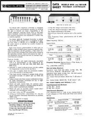
NOTEOnly qualified service technicians should perform thesemodifications.These internal adjustments require only removal of the topcover:1. Remove battery compartment.2. Remove four screws securing two plastic end caps and oneground-bonding screw on the side opposite the battery compartment.3. Slowly slide cover up and off chassis.INTERNAL ADJUSTMENTS4. Adjust the 1 kHz tone oscillator level with the Master gain controluntil the ac voltmeter reading is at the level desired5. With the <strong>M367</strong> top cover removed, adjust the VU Level Calibrationtrim pot R684 with a screwdriver until the VU Meterreads 0.6. For 0 VU settings between +4 and +8 dBm, set internal DIPswitch S701 position 1 "down", and perform steps 1 through 5.VCA DISTORTION TRIMPOT (R607)DO NOT ADJUST! This potentiometer is precisely calibrated oneach mixer for minimum distortion.VU METER ADJUSTMENT (R684)This trimpot adjusts the VU meter to indicate 0 VU at a presetoutput level. The factory setting is +4 dBm. The user adjustmentrange is -10 dBV to +4 dBm (-6 dBV to +8 dBm with DIP switch 1down).To set the VU meter to a value other than the factory setting(0 VU = +4 dBm), proceed as follows:1. Connect a 600 Ω load to an XLR output set for Line.2. Connect an ac voltmeter with 1 MΩ or greater inputimpedance (Fluke 77 or equivalent) in parallel with the load.3. Set the 1 kHz tone oscillator switch to the ON position.VU METERCALIBRATIONTRIMPOTR684(ACCESSEDTHROUGHHOLE INUPPER FRONTPC BOARD)VCADISTORTIONTRIMPOTR607DIP SWITCHS701INTERNAL ADJUSTMENTSFIGURE 57