
You also want an ePaper? Increase the reach of your titles
YUMPU automatically turns print PDFs into web optimized ePapers that Google loves.
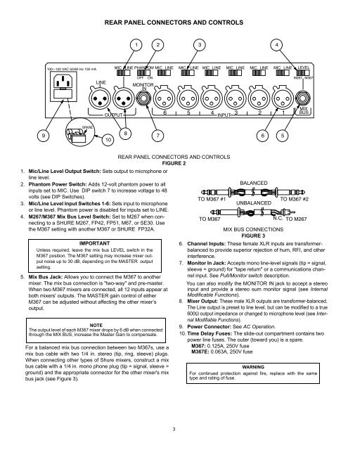
ÑÑÑÑREAR PANEL CONNECTORS AND CONTROLS ÑÑÑÑÑ Ñ ÑÑÑÑÑÑÑÑÑÑÑÑÑÑÑ ÑÑÑÑÑÑÑÑÑÑÑÑÑÑÑ Ñ ÑÑÑÑÑÑÑÑÑÑÑÑÑÑÑÑÑÑÑÑÑÑÑÑÑÑÑÑÑÑÑÑÑÑÑÑÑÑÑÑ ÑÑÑÑÑÑÑÑÑÑÑ ÑÑÑÑÑÑÑÑÑÑÑÑÑÑÑÑÑÑÑÑÑÑÑÑÑÑÑÑ ÑÑÑÑÑÑÑÑÑÑÑÑÑÑÑÑÑÑÑÑÑÑÑÑÑÑÑ ÑÑÑÑ ÑÑÑÑÑÑÑÑÑÑÑÑÑÑÑÑÑÑÑÑÑÑÑÑÑÑÑÑÑÑÑÑÑÑ1. Mic/Line Level Output Switch: Sets output to microphone orline level.2. Phantom Power Switch: Adds 12-volt phantom power to allinputs set to MIC. Use DIP switch 7 to increase voltage to 48volts (see DIP Switches).3. Mic/Line Level Input Switches 1-6: Sets input to microphoneor line level. Phantom power is disabled for inputs set to LINE.4. M267/<strong>M367</strong> Mix Bus Level Switch: Set to M267 when connectingto a SHURE M267, FP42, FP51, M67, or SE30. Usethe <strong>M367</strong> setting with another <strong>M367</strong> or SHURE FP32A.IMPORTANTUnless required, leave the mix bus LEVEL switch in the<strong>M367</strong> position. The <strong>M367</strong> setting may increase mixer outputnoise up to 30 dB, depending on the MASTER outputsetting.5. Mix Bus Jack: Allows you to connect the <strong>M367</strong> to anothermixer. The mix bus connection is "two-way" and pre-master.When two <strong>M367</strong> mixers are connected, all 12 inputs appear atboth mixers' outputs. The MASTER gain control of either<strong>M367</strong> can be adjusted without affecting the other mixer’soutput.NOTEThe output level of each <strong>M367</strong> mixer drops by 6 dB when connectedthrough the MIX BUS, increase the Master Gain to compensate.For a balanced mix bus connection between two <strong>M367</strong>s, use amix bus cable with two 1/4 in. stereo (tip, ring, sleeve) plugs.When connecting other types of <strong>Shure</strong> mixers, construct a mixbus cable with a 1/4 in. mono phone plug (tip = signal, sleeve =ground) and the appropriate connector for the other mixer's mixbus jack (see Figure 3).REAR PANEL CONNECTORS AND CONTROLSFIGURE 2BALANCEDTO <strong>M367</strong> #1 TO <strong>M367</strong> #2UNBALANCEDTO <strong>M367</strong>ÔÔÔÔMIX BUS CONNECTIONSFIGURE 36. Channel Inputs: These female XLR inputs are transformerbalancedto provide superior rejection of hum, RFI, and otherinterference.7. Monitor In Jack: Accepts mono line-level signals (tip = signal,sleeve = ground) for "tape return" or a communications channelinput. See Pull/Monitor switch description.You can also modify the MONITOR IN jack to accept a stereoinput and provide a stereo sum monitor signal (see InternalModificable Functions).8. Mixer Output: These male XLR outputs are transformer-balanced.The Line output is preset to line level, but can be modified to a true600Ω output impedance or changed to microphone level (see InternalModifiable Functions).9. Power Connector: See AC Operation.10. Time Delay Fuses: The slide-out compartment contains twopower line fuses. The outer (toward you) is a spare.<strong>M367</strong>: 0.125A, 250V fuse<strong>M367</strong>E: 0.063A, 250V fuseÔÔÔÔN.C. TO M267WARNINGFor continued protection against fire, replace with the sametype and rating of fuse.3