Create successful ePaper yourself
Turn your PDF publications into a flip-book with our unique Google optimized e-Paper software.
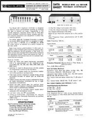
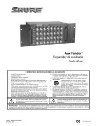
ÑÑÑÑREAR PANEL CONNECTORS AND CONTROLS ÑÑÑÑÑ Ñ ÑÑÑÑÑÑÑÑÑÑÑÑÑÑÑ ÑÑÑÑÑÑÑÑÑÑÑÑÑÑÑ Ñ ÑÑÑÑÑÑÑÑÑÑÑÑÑÑÑÑÑÑÑÑÑÑÑÑÑÑÑÑÑÑÑÑÑÑÑÑÑÑÑÑ ÑÑÑÑÑÑÑÑÑÑÑ ÑÑÑÑÑÑÑÑÑÑÑÑÑÑÑÑÑÑÑÑÑÑÑÑÑÑÑÑ ÑÑÑÑÑÑÑÑÑÑÑÑÑÑÑÑÑÑÑÑÑÑÑÑÑÑÑ ÑÑÑÑ ÑÑÑÑÑÑÑÑÑÑÑÑÑÑÑÑÑÑÑÑÑÑÑÑÑÑÑÑÑÑÑÑÑÑ1. Mic/Line Level Output Switch: Sets output to microphone orline level.2. Phantom Power Switch: Adds 12-volt phantom power to allinputs set to MIC. Use DIP switch 7 to increase voltage to 48volts (see DIP Switches).3. Mic/Line Level Input Switches 1-6: Sets input to microphoneor line level. Phantom power is disabled for inputs set to LINE.4. M267/<strong>M367</strong> Mix Bus Level Switch: Set to M267 when connectingto a SHURE M267, FP42, FP51, M67, or SE30. Usethe <strong>M367</strong> setting with another <strong>M367</strong> or SHURE FP32A.IMPORTANTUnless required, leave the mix bus LEVEL switch in the<strong>M367</strong> position. The <strong>M367</strong> setting may increase mixer outputnoise up to 30 dB, depending on the MASTER outputsetting.5. Mix Bus Jack: Allows you to connect the <strong>M367</strong> to anothermixer. The mix bus connection is "two-way" and pre-master.When two <strong>M367</strong> mixers are connected, all 12 inputs appear atboth mixers' outputs. The MASTER gain control of either<strong>M367</strong> can be adjusted without affecting the other mixer’soutput.NOTEThe output level of each <strong>M367</strong> mixer drops by 6 dB when connectedthrough the MIX BUS, increase the Master Gain to compensate.For a balanced mix bus connection between two <strong>M367</strong>s, use amix bus cable with two 1/4 in. stereo (tip, ring, sleeve) plugs.When connecting other types of <strong>Shure</strong> mixers, construct a mixbus cable with a 1/4 in. mono phone plug (tip = signal, sleeve =ground) and the appropriate connector for the other mixer's mixbus jack (see Figure 3).REAR PANEL CONNECTORS AND CONTROLSFIGURE 2BALANCEDTO <strong>M367</strong> #1 TO <strong>M367</strong> #2UNBALANCEDTO <strong>M367</strong>ÔÔÔÔMIX BUS CONNECTIONSFIGURE 36. Channel Inputs: These female XLR inputs are transformerbalancedto provide superior rejection of hum, RFI, and otherinterference.7. Monitor In Jack: Accepts mono line-level signals (tip = signal,sleeve = ground) for "tape return" or a communications channelinput. See Pull/Monitor switch description.You can also modify the MONITOR IN jack to accept a stereoinput and provide a stereo sum monitor signal (see InternalModificable Functions).8. Mixer Output: These male XLR outputs are transformer-balanced.The Line output is preset to line level, but can be modified to a true600Ω output impedance or changed to microphone level (see InternalModifiable Functions).9. Power Connector: See AC Operation.10. Time Delay Fuses: The slide-out compartment contains twopower line fuses. The outer (toward you) is a spare.<strong>M367</strong>: 0.125A, 250V fuse<strong>M367</strong>E: 0.063A, 250V fuseÔÔÔÔN.C. TO M267WARNINGFor continued protection against fire, replace with the sametype and rating of fuse.3
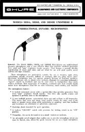
AC OPERATIONUse the supplied power adapter to connect the <strong>M367</strong> to a poweroutlet.<strong>M367</strong>: 100-120 VAC, 50/60 Hz<strong>M367</strong>E: 220-240 VAC, 50/60 HzThe operating voltage can be switched internally (see InternalModifiable Functions).NOTEAppliance inlet is the main disconnect device (to power off the<strong>M367</strong>, you must unplug the power supply).BATTERY OPERATIONOpen the battery compartment by grasping the sides of thecompartment, squeezing to release the locks, and pulling the compartmentoutward. Insert two 9-volt batteries.During battery operation, use the BATT CHECK button. Pressand hold to show battery level on the VU meter. Press once to illuminatethe VU switch for 10 seconds, or set DIP switch 6 for continuousillumination (see DIP Switches).BATTERY LIFEWith two fresh 9-volt alkaline batteries, the <strong>M367</strong> operates forabout eight hours. Some mixer features decrease battery life, as illustratedin the following table.SETTING LEVELS1. Set the MASTER gain knob to the full off position.2. Activate the 1 khz tone oscillator by setting the 1 KHZ TONEswitch to ON. Adjust the MASTER gain until the VU meterneedle indicates "0". Adjust the input levels on the equipmentconnected to the <strong>M367</strong> outputs accordingly. Deactivate thetone by setting the 1 KHZ TONE switch to OFF.3. Adjust the Input gain controls based on the incoming signallevels. The input PEAK LEDs should flicker red only on loudinput peaks.4. Observe the output on the VU meter and adjust the MASTERgain to obtain the desired levels. try to keep the average levelsaround "0 VU". The PEAK LED adjacent to the VU metershould illuminate only on loud output peaks.DIP SWITCHES1 2 3 4 5 6 7S701Access the DIP switches by removing the battery compartmentand top cover. Use the following table to set the switches(Bold = factory setting.)NOTEMomentary use of headphones or meter illumination will notappreciably affect battery life.SwitchFunction Up DownMixer OperationBatteryCurrent(mA)BatteryLife(hours)*No Signal 40 9With +4 dBm continuous output 45 8With six mics at 12 V phantom power 55 6.5With six mics at 48 V phantom power 70 5With output to headphones 50 71 Meter 0 VU 0 VU = +4 dBm 0 VU = +8 dBm2 LimiterThreshold34 Program toMonitorOffSee Figure 4On (adds attenuatedprogram signalin headphones withPull/Monitor switchon)With meter illumination continuously on 75 4.5*until Power LED begins to flash, allowing approximately 30 minutesto replace batteries.CONNECTING <strong>M367</strong> OUTPUTS TO TELEPHONE LINESUse the XLR outputs at line level to drive dc-biased, "dialed up"telephone lines. A slight increase in distortion may occur. Use the<strong>M367</strong> limiter with the limiter threshold set to +4 dBm. Modify the<strong>M367</strong> output impedance to 600 Ω for proper fidelity (see InternalModifiable Functions). When connecting the <strong>M367</strong> to a telephoneline, you must use an FCC-Registered interface adapter betweenthe mixer and telephone line.5 Monitor InGain6 VU Lamp (BattCheck button)7 PhantomPowerNormalTimed (Turns offafter 10 seconds)HighToggled (press on,press off)12 Vdc 48 VdcLimiter Threshold= +16 dBm= +8 dBm= +4 dBm2 3= 0 dBmLIMITER THRESHOLD SETTINGSFIGURE 44
SPECIFICATIONSFrequency ResponsePolarity20 to 20,000 Hz ± 2.0 dB (channel controls centered)Total Harmonic Distortion0.25% THD at +4 dBm output, 55 to 20,000 HzVoltage GainOutputMic/Line In to Mic/Line OutMic/Line In to PhonesMic/Line In to Mix Bus (tip)Monitor to PhonesNon-InvertingNon-InvertingInvertingNon-InvertingInput Line Mic Phones Mix Bus(<strong>M367</strong>)Low-Z Mic(150 Ω)InputsOutputsMixBus(M267)87 dB 40 dB 103 dB 66 dB 27 dBLine 37 dB -11 dB 53 dB 15 dB -25 dBMonitor -- -- 12 dB -- --Mix Bus(<strong>M367</strong>)MixBus(M267)10 dB -38 dB 26 dB -- --50 dB 2 dB 66 dB -- --IMPEDANCEInputInput Designed for Actual ClippingUse With (Internal) LevelMic 19 to 600 Ω 1 kΩ -10 dBVLine ≤10 kΩ 50 kΩ +36 dBVMonitor ≤1 kΩ 13 kΩ 0 dBVMix Bus(<strong>M367</strong>)Mix Bus(M267)930 Ω bal.;1860 Ω unbal.930 Ω bal.;1860 Ω unbal.+23 dBV3.5 kΩ 3.5 kΩ -17 dBVIMPEDANCEOutputOutput Designed for Actual ClippingUse With (Internal) LevelMic Low-Z inputs 1 Ω -31 dBVLine 600 Ω 150 Ω +18 dBmPhones 8 to 200 Ω 300 Ω +11 dBVMix Bus(<strong>M367</strong>)Mix Bus(M267)930 Ω bal.;1860 Ω unbal.930 Ω bal.;1860 Ω unbal.+11 dBV3.5 kΩ 3.5 kΩ -28 dBVEquivalent Input Noise≤ –127 dBV with 150 Ω source, 400 to 20,000 HzOutput NoiseMaster level full CCW: –100 dBV, 400 to 20,000 HzMaster level full CW: –80 dBV, 400 to 20,000 HzHum and NoiseEquivalent Input: ≤125 dBV, 20 to 20,000 HzOutput: –95 dBV (Master CCW), –75 dBV; (Master CW), 20 to20,000 HzCommon Mode Rejection Ratio65 dB at 100 Hz, –20 dBV inputMix Bus to Mic/Line OutInvertingOverload and ShortingShorted outputs, even for prolonged periods, cause no damage.Microphone inputs of up to 3 Vrms cause no damage. Line andmonitor can withstand signals of up to 30 Vrms.Input Peak Indicators6 dB below clipping levelOutput Peak IndicatorLights red at 6 dB below clipping levelOutput Clipping Level≤ +18 dBm at line output into 600 ΩLow-Cut Filters7 dB down at 150 Hz; 6 dB/octave slope (3 dB down at 260 Hz)Tone Oscillator1 kHz ± 20%LimiterThreshold: Switchable: 0, +4, +8, +16 dBmAttack Time: 1 ms ± 0.5 msRelease Time Constant: 100 ms ± 30 msIndicator: Green when limiting by 1 dB or morePhantom Power12 V Phantom: 12 V through 340 Ω48 V Phantom : 48 V through 3.4 kΩAC Power<strong>M367</strong>: 100–120 Vac, 50/60 Hz, 100 mA<strong>M367</strong>E: 220–240 Vac, 50/60 Hz, 50 mA; no-signal current drain25 mADC Power18 Vdc nominal at 40 mA typical no-signal, 45 mA typical at +4dBm output; 13.5 Vdc minimumBatteriesTwo 9 V alkaline batteriesBattery LifeUp to 8 hours* at +4 dBm output in continuous use.*(see Battery Operation)Temperature RangeOperating: -18° to 57° C (0° to 135° F)Storage: -29° to 74°C (-20° to 165° F)Overall Dimensions (H x W x D)71.9 mm x 308 mm x 233 mm (2 13/16 in. x 125/32 in. x 9 5/32 in.) including feet.Weight (without batteries)3 kg (6.6 lb)Measurement conditions (unless otherwise specified): operatingvoltage 120 Vac, 60 Hz (18 ±1 Vdc for dc test); operating temperature22°C (72°F); input signal 1 kHz; internal DIP switches 1–7 open;Power switch on; Mic/Line switches to Line; low-cut switches to flat;Limiter out; Phantom power off; Mix Bus to <strong>M367</strong>; channel 1 gain fullCW; channel 2 through 6 full CCW; Master full CW; Phones level fullCCW; Line output terminations 600 Ω (pins 2 and 3); Mic output terminations150 Ω (pins 2 and 3); Phones (1/4"–ring) 300 Ω to ground;Phones (1/4"–tip) 300 Ω to ground; Phones (3.5 mm) unloaded; MixBus 930 Ω (<strong>M367</strong> position) or 3.5 kΩ (M267 position), not connectedunless specified; 1 kHz input signal.5
REPLACEMENT PARTSFoot Kit (4 in kit)........................................................... 90S8100<strong>M367</strong> Fuse, 0.125 A, 250 V ........................................... 80E380<strong>M367</strong>E Fuse, 0.063 A, 250 V......................................... 80G380KnobMaster .......................................................................... 95A8238Channel Gain, Phones................................................. 95B8238Line (Power) Cord<strong>M367</strong> ............................................................................ 95A8389<strong>M367</strong>E.......................................................................... 95B8389OPTIONAL ACCESSORIESRack Mount Kit.................................................................A367RSTATEMENT OF CONFORMITYConforms to European Union directives, eligible to bear CEmarking; VDE GS-Certified to EN60065; meets European UnionEMC Immunity Requirements (EN 50 082-1, 1992): RF radiated(IEC 801-3): meets Criterion A, ESD: meets Criterion B, EFT(IEC 801-4): meets Criterion B.GENERAL INFORMATIONChanges or modifications not expressly approved by <strong>Shure</strong>, Inc.could void your authority to operate this equipment.This equipment has been tested and found to comply with the limitsfor a Class B digital device pursuant to Part 15 of the FCC Rulesand as set out in the Radio Interference Regulations of the CanadianDepartment of Communications. These limits are designed toprovide reasonable protection against harmful interference in aresidential installation. This equipment generates, uses, and canradiate radio frequency energy and, if not installed and used in accordancewith the instructions, may cause harmful interference toradio communications. However, there is no guarantee that interferencewill not occur in a particular installation. If this equipmentcauses harmful interference to radio or television reception, determinedby turning the equipment off and on, try to correct the interferenceby one or more of the following measures:1. Reorient or relocate the receiving antenna.2. Increase the separation between the equipment and receiver.3. Connect the equipment into an outlet on a circuit different fromthat to which the receiver is connected.4. Consult the dealer or an experienced radio/TV technicianfor help.6
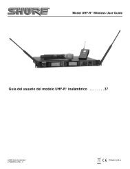
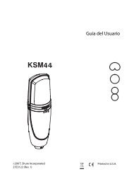
NOTEOnly qualified service technicians should perform thesemodifications.These internal adjustments require only removal of the topcover:1. Remove battery compartment.2. Remove four screws securing two plastic end caps and oneground-bonding screw on the side opposite the battery compartment.3. Slowly slide cover up and off chassis.INTERNAL ADJUSTMENTS4. Adjust the 1 kHz tone oscillator level with the Master gain controluntil the ac voltmeter reading is at the level desired5. With the <strong>M367</strong> top cover removed, adjust the VU Level Calibrationtrim pot R684 with a screwdriver until the VU Meterreads 0.6. For 0 VU settings between +4 and +8 dBm, set internal DIPswitch S701 position 1 "down", and perform steps 1 through 5.VCA DISTORTION TRIMPOT (R607)DO NOT ADJUST! This potentiometer is precisely calibrated oneach mixer for minimum distortion.VU METER ADJUSTMENT (R684)This trimpot adjusts the VU meter to indicate 0 VU at a presetoutput level. The factory setting is +4 dBm. The user adjustmentrange is -10 dBV to +4 dBm (-6 dBV to +8 dBm with DIP switch 1down).To set the VU meter to a value other than the factory setting(0 VU = +4 dBm), proceed as follows:1. Connect a 600 Ω load to an XLR output set for Line.2. Connect an ac voltmeter with 1 MΩ or greater inputimpedance (Fluke 77 or equivalent) in parallel with the load.3. Set the 1 kHz tone oscillator switch to the ON position.VU METERCALIBRATIONTRIMPOTR684(ACCESSEDTHROUGHHOLE INUPPER FRONTPC BOARD)VCADISTORTIONTRIMPOTR607DIP SWITCHS701INTERNAL ADJUSTMENTSFIGURE 57
INTERNAL MODIFIABLE FUNCTIONSNOTEOnly qualified service technicians should perform thesemodifications.Perform all modifications through solder points accessible onthe main PC board.DISASSEMBLING THE <strong>M367</strong>1. Remove the mixer top cover as previously described.2. Carefully remove three multi-pin cable assembly connectorsfrom upper front PC board (nearest front panel). Remove thethree Phillips head screws securing the PC board. Remove upper front PC board.3. Carefully remove four multi-pin cable assembly connectorsfrom upper rear PC board (nearest rear panel). Remove thethree Phillips head screws securing the PC board. Removeupper rear PC board.4. Perform modification (refer to appropriate following procedure).Note that all modifications can be performed withoutremoving the main PC board.5. Reassemble <strong>M367</strong> by performing above steps in reverse,assembling the Phillips screws in the order indicated on theupper front and upper rear PC boards.CHANGING LINE LEVEL OUTPUT IMPEDANCE TO 600 ΩLocate resistor R621 (near IC U602 pin 8) on the main PC boardand remove it. Locate empty pads X621 (near resistor R621).Solder a 430 Ω, 1/2 W resistor through the holes at X621.CHANGING UNSWITCHED LINE OUTPUT TO MIC LEVELLocate resistor R632 (near output transformer T601) andremove. Locate empty pads X632 (near transformer T601). Soldera jumper wire through the holes of X632.CHANGING MIXER AUDIO LEVELS IN HEADPHONES(Pull/Monitor Switch Activated, DIP Switch S701 Position4 Closed)Locate empty pads X649 (near Phones potentiometer R648).Solder a 68 kΩ, 1/4 W resistor through the holes at X649 to hearprogram audio 12 dB down from standard headphones level withPull/ Monitor switch on (pulled out). Solder a 24 kΩ, 1/4 W resistorthrough the holes at X649 to hear program audio 6 dB fromstandard headphones level with Pull/Monitor switch on (pulled out).CHANGING LOW-CUT FILTER CORNER FREQUENCY(3 DB DOWN POINT)Pad Channel Pad ChannelX421 1 X451 4X431 2 X521 5X441 3 X531 62. Locate the following empty pads:Find all pads near ribbon cable assemblies W811, W812 andW813.3. Solder a new capacitor through the holes of the empty padsfor each channel to be modified.To increase corner frequency:Note: Low-cut corner frequencies much higher than the factorypreset of 260 Hz may excessively attenuate desired low- tomid-frequency program material.1. Locate the following capacitors near empty pads:Capacitor Pad Channel Capacitor Pad ChannelC425 X421 1 C455 X451 4C435 X431 2 C525 X521 5C445 X441 3 C535 X531 62. Remove the indicated capacitor for each channel to bemodified.3. Calculate new capacitor value for higher high-cut corner frequency. Use the following formula:C in μF= (85/frequency)Example: for 400 Hz corner frequency,C = (85/400) = 0.21For 400 Hz corner frequency, use a 0.22 μF capacitor.4. Solder a new capacitor through the holes of the empty padsfor each channel to be modified.SLOWING OUTPUT METER FROM "True VU" BALLISTICSLocate empty pads X691 (at left of VU meter M1). Solder a 100μF x 6.3 V electrolytic capacitor through the holes of X691. Observecapacitor polarity as marked on the PC board. The responsetime is now 500 ms with no overshoot. To further slow the meterresponse, use a larger capacitor value.CHANGING MIC LEVEL OUTPUT IMPEDANCELocate resistor R631 (near output transformer T601) andremove it. Locate empty pads X631 (near T601). Solder desiredvalue 1/4 W resistor through the holes of X631. For example, usea 150 Ω, 1/4 W resistor for 150 Ω output impedance.To decrease corner frequency:1. Calculate new capacitor value for lower low-cut cornerfrequency. Use the following formula:C in μF= (85/frequency) - 0.33Example: for 200 Hz corner frequency,85/200 9 0.430.43 - 0.33 = 0.1For 200 Hz corner frequency, use a 0.1 μF capacitor.NOTE:Capacitor must be non-polarized; ceramic or film type;16V rating or higher.8
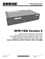
ADAPTING LINE OUT TO DUAL BANANA JACKAdd a dual banana jack, balanced, line-level output capability bypurchasing a commercial unit (Sescom XLR F-3BP or equivalent),or obtaining a female XLR connector (Radio Shack 274-011 orequivalent), a dual banana jack (ITT 2269 or equivalent), a smallutility box, and a short length of high-quality shielded output cableand constructing the adapter shown in Figure 6.ËËÑÑËËCHANGING MONITOR IN HIGH GAIN (DIP Switch S701Position 5 Down)Locate resistor R647 (near Phones potentiometer R648) and removeit. Locate empty pads X647 (near R647). Solder a 330 Ω,1/4 Wresistor in the holes of X647 for 6 dB gain boost with DIP switch S701position 5 down (input impedance equals 6.5 kΩ in this position).CHANGING MONITOR IN JACK FROM MONO INPUT TOSTEREO SUM INPUTLocate empty pads X645 (near Monitor In jack J863). Solder a1 kΩ, 1%, 1/4 W resistor in the holes of X645. The Monitor In jackwill now accept a stereo input signal (tip left, ring right, sleeveground), and sum these signals to the monitor circuit.1 2NOTE3DUAL BANANA JACK OUTPUTFIGURE 6Connect this adapter to the <strong>M367</strong> Line output.CHANGING MONITOR IN TO AUX INNOTE:This modification disables the <strong>M367</strong>'s monitor function.Remove resistors R642 and R647 (near Phones potentiometerR648).Locate empty pads X601 (near output transformer T601) andX643 (near Monitor In jack J683).Solder a jumper wire from X643 to X601. The Monitor In jack isnow an unbalanced (tip positive, sleeve ground) Aux In jack, withan input impedance of 11 kΩ and a maximum gain to Line Out(loaded with 600 Ω) of 17 dB. The Aux In signal is only controlledby the Master control.To change Aux In gain, locate resistor R605 (near X601). Carefully remove R605 and replace it with a surface-mount resistor(0805 package) of the desired value. If replacing R605 with 15 kΩ,maximum Aux In to Line Out gain equals 14 dB and inputimpedance equals 16 kΩ; if replaced with 6.8 kΩ, maximum Aux Into Line Out gain equals 20 dB and input impedance equals 7.8 kΩ.If using a true stereo feed to drive the <strong>M367</strong> Monitor In andanother stereo device, the source impedance must be 20 Ω orless to maintain at least 40 dB separation in the stereo device.Use a stereo distribution amplifier or buffer to maintain optimumstereo separation.MASTER GAIN REMOTE CONTROLNOTEThis modification disables both the <strong>M367</strong>'s monitor function andits front-panel Master gain control.1. Remove resistor R641 (near Monitor In jack J863).2. Remove resistor R746 (near Master potentiometer R706).3. Locate empty pad X702 (near Master potentiometer R706).Solder one end of a 100 Ω, 1/4 W resistor in the hole of X702.Solder an insulated wire to the other end of the 100 Ω resistor.Locate empty pad X644 (near jack J863). Solder the other endof the insulated wire to X644.4. Locate empty pad X701 (next to empty pad X702). Solder aninsulated wire to X701. Locate empty pads X645 (near jackJ863). Solder the other end of the insulated wire to the emptypad X645 nearest channel 6 input connector J856.5. Construct a remote control potentiometer/cable assembly asshown in Figure 7.TIPÑÑËËRINGCWSLEEVEMASTER GAIN REMOTE CONTROLFIGURE 7Recommended parts are:Potentiometer, 10-25 kΩ, linear taper (Radio Shack271-1715)1/4 in. Stereo Phone Plug (Switchcraft 280)Ferrite Bead Rings (Ferronics 21-031J)Capacitors, ceramic, 0.001 μF, 50 VCable, 2-conductor, shielded, 50 ft maximum (15 m)Ferrite bead rings and capacitors should be as close to thephone plug as possible.6. Insert the phone plug in the Monitor In jack. The remote controlpotentiometer now controls <strong>M367</strong> gain with a control tapersimilar to that of the Master gain control.9
CHANGING LIMITER RELEASE TIME TO ONE SECONDRemove resistor R741 (about 15 mm behind ribbon cableassembly W813).CHANGING LIMITER THRESHOLD PRESETS1. Select the equivalent resistor values for the desired limiterthresholds from the following table. Then fill in the followingwork sheet with the resistor selections.Limiter Threshold(dBm into 600 Ω)R equiv(kΩ)Limiter Threshold (dBm into 600 Ω)R equiv(kΩ)0 18 10 811 21 11 932 25 12 1053 30 13 1224 35 14 1395 41 15 1566 47 16 1757 54 17 1948 62 18 2159 71DIP Switch S701 Limiter Threshold R equiv (above)Position 2 Position 3–dBm –up up high _____ kΩ = R1down up med. high _____ kΩ = R2up down med. low _____ kΩ = R3down down low _____ kΩ = R42. Remove resistors R721, R731, R732, R733, R734 and R735(surrounding IC U704).3. Locate empty pads X732, X733, X734 and X735 (surroundingIC U704).4. Select a 1/4 W, 1% resistor closest in value to R1 (from thework sheet), and solder it to the holes of X732.Note: Use parallel or series combinations of resistors to matchthe chosen values as closely as possible if 1% resistors are notavailable.5. Calculate resistor R5 value as follows:R5 =11R2 – 1R1Select a 1/4 W, 1% resistor closest in value to R5 and solder itto the holes of X733.6. Calculate resistor R6 value as follows:Select a 1/4 W, 1% resistor closest in value to R6 and solder itto the holes of X734.7. Calculate resistor R7 value as follows:Select a 1/4 W, 1% resistor closest in value to R7 and solder itto the holes of X735. (See Changing Limiter Threshold Presets:Samples Calculations later in the Appendix for an example oflimiter threshold preset component calculations.)CHANGING LIMITER THRESHOLD PRESETS: SAMPLESCALCULATIONSFor the following limiter thresholds:DIP Switch S701 Limiter Threshold R equivPosition2R7 =R6 =Position31R4 – 1R111R3 – 1R1– dBm –up up high 12 105kΩ=R1down up med. high 8 62 kΩ=R2up down med. low 4 35 kΩ=R3down down low 0 18 kΩ=R41. Obtain a 105 kΩ, 1/4 W, 1% resistor and solder it to the holesof X732.2. Obtain a 150 kΩ, 1/4 W, 1% resistor and solder it to the holesof X733.R 5=3. Obtain a 52.3 kΩ, 1/4 W, 1% resistor and solder it to the holesof X734.4. Obtain a 49.9 kΩ, 1/4 W, 1% resistor and solder it to the holesof X735.1–11 162,000 105,0001R 6= 1 135,000 105,0001R 7= 1 1118,000 105,000 150,0001R5 – 1R6= 151.4 k= 52.5 k152,300= 49.4 k10
SHURE Incorporated http://www.shure.comUnited States, Canada, Latin America, Caribbean:5800 W. Touhy Avenue, Niles, IL 60714-4608, U.S.A.Phone: 847-600-2000 U.S. Fax: 847-600-1212 Intl Fax: 847-600-6446Europe, Middle East, Africa:<strong>Shure</strong> Europe GmbH, Phone: 49-7131-72140 Fax: 49-7131-721414Asia, Pacific:<strong>Shure</strong> Asia Limited, Phone: 852-2893-4290 Fax: 852-2893-4055