Operating Instructions - Snap-on Equipment
Operating Instructions - Snap-on Equipment Operating Instructions - Snap-on Equipment
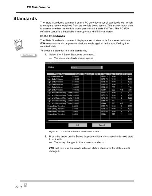
PC MaintenanceStandardsThe State Standards command on the PC provides a set of standards with whichto compare results obtained from the vehicle being tested. This makes it possibleto assess whether the vehicle would pass or fail a state I/M Test. The PC FGAsoftware contains all available state-by-state Idle/TSI standards.State StandardsThe State Standards command displays a set of standards for a selected state.FGA measures and compares emissions levels against limits specified by theselected state.To choose a state for its state standards,1. Select the 9 State Standards command.— The state standards screen opens.Figure 3G-17: Customer/Vehicle Information Screen2. Press the arrow on the States drop-down list and choose the desired statefrom the list.— The array changes to that state’s standards.FGA will now use the newly selected state’s standards for all tests untilchanged.3G-14
PC MaintenanceDiagnosticsService utilities include diagnostics and setup. Diagnostics provides a means ofanalyzing and diagnosing problems in the analyzer. Setup allows you to specifybasic settings.Diagnostics is a process of diagnosing problems that may occur within the gasanalyzer. The Diagnostics window in the FGA software is not intended to functionas a measurement tool.To begin Diagnostics,1. Press the Gas button.— The Gas button menu opens.2. Choose Service Utilities.— The Service Utilities menu displays two commands: Diagnostics andSetup.3. Choose Diagnostics.The system then prompts you to enter a password.Figure 3G-18: Service Password ScreenEnter the password and press Continue. The default is “STATION” (alluppercase). The Diagnostics window opens showing System Statusdiagnostics. For more information about the password, see ChangePassword, page 3H-1.3G-15
- Page 99 and 100: 3APC Software OverviewThe PC versio
- Page 101 and 102: PC Software OverviewCommands 1-10Co
- Page 103 and 104: PC Software OverviewCommandsFigure
- Page 105 and 106: 3BPC SoftwareInstallationThe Flexib
- Page 107 and 108: PC Software Installation5. If this
- Page 109 and 110: 3CPC Meters/Strip ChartThis chapter
- Page 111 and 112: PC Meters/GraphGas Bench MenuThe Ga
- Page 113 and 114: PC Meters/GraphStrip ChartTo view t
- Page 115 and 116: PC Meters/GraphStrip Chart Display
- Page 117 and 118: PC Meters/GraphWhen you select the
- Page 119 and 120: PC Meters/GraphTachometerUse the Ta
- Page 121 and 122: PC Automatic Tests3DTSI TestThis se
- Page 123 and 124: PC Automatic TestsTachometer Config
- Page 125 and 126: PC Automatic TestsIdle RPM TestFGA
- Page 127 and 128: PC Automatic TestsTSI Results16. Th
- Page 129 and 130: 3EPC Customer/VehicleFGA is designe
- Page 131 and 132: PC Customer/VehicleInformation bar
- Page 133 and 134: PC Customer/VehicleWhen the desired
- Page 135 and 136: 3FPC ResultsThe Test Results window
- Page 137 and 138: 3GPC MaintenanceGas CalibrationThis
- Page 139 and 140: PC Maintenance5. Attach the calibra
- Page 141 and 142: PC MaintenanceNew NO x SensorNew NO
- Page 143 and 144: PC MaintenanceShop InformationThe S
- Page 145 and 146: PC MaintenanceThe Setup window cont
- Page 147 and 148: PC MaintenanceTSI Test SetupThe TSI
- Page 149: PC MaintenanceZero Purge Time(s)—
- Page 153 and 154: PC Other Functions3HThis chapter co
- Page 155 and 156: 4General MaintenanceThis chapter ad
- Page 157 and 158: General MaintenanceOptionsPart Numb
- Page 159 and 160: General Maintenance3. Select the Ig
- Page 161 and 162: General MaintenanceWhen using the O
- Page 163 and 164: General Maintenance—Push the gray
- Page 165 and 166: General MaintenanceWhen FGA softwar
- Page 167 and 168: 5InterpretationThe section includes
- Page 169 and 170: Interpretation• Minimal NO is pro
- Page 171 and 172: Interpretation2. Repair the vehicle
- Page 173 and 174: Interpretation:The following is a c
- Page 175 and 176: AAppendix A:OBD II ConnectionsThe l
- Page 177 and 178: LIMITED WARRANTYTERMS AND CONDITION
PC MaintenanceStandardsThe State Standards command <strong>on</strong> the PC provides a set of standards with whichto compare results obtained from the vehicle being tested. This makes it possibleto assess whether the vehicle would pass or fail a state I/M Test. The PC FGAsoftware c<strong>on</strong>tains all available state-by-state Idle/TSI standards.State StandardsThe State Standards command displays a set of standards for a selected state.FGA measures and compares emissi<strong>on</strong>s levels against limits specified by theselected state.To choose a state for its state standards,1. Select the 9 State Standards command.— The state standards screen opens.Figure 3G-17: Customer/Vehicle Informati<strong>on</strong> Screen2. Press the arrow <strong>on</strong> the States drop-down list and choose the desired statefrom the list.— The array changes to that state’s standards.FGA will now use the newly selected state’s standards for all tests untilchanged.3G-14


