Operating Instructions - Snap-on Equipment
Operating Instructions - Snap-on Equipment Operating Instructions - Snap-on Equipment
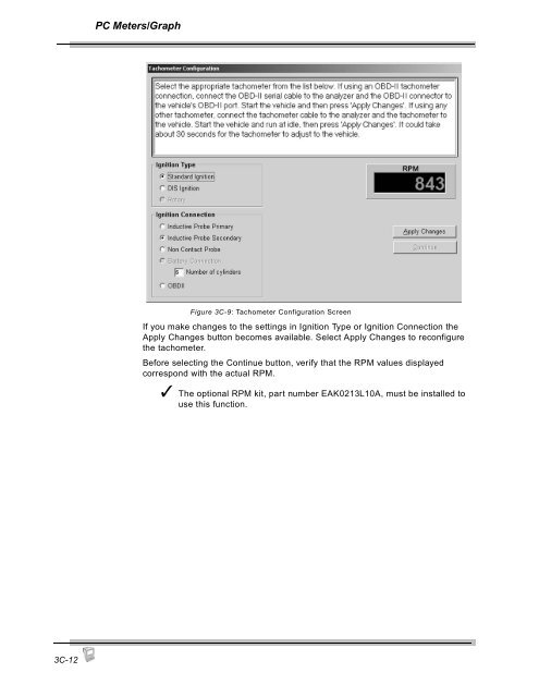
PC Meters/GraphFigure 3C-9: Tachometer Configuration ScreenIf you make changes to the settings in Ignition Type or Ignition Connection theApply Changes button becomes available. Select Apply Changes to reconfigurethe tachometer.Before selecting the Continue button, verify that the RPM values displayedcorrespond with the actual RPM.✓ The optional RPM kit, part number EAK0213L10A, must be installed touse this function.3C-12
PC Automatic Tests3DTSI TestThis section describes the Gas Emissions Tests, the primary function of theanalyzer.• TSI Test, page 3D-1• Idle Test, page 3D-8• Meters, page 3D-8• Tachometer, page 3D-8The Two Speed Idle Test (TSI) provides standardized testing so the techniciansrun the test in a similar manner from vehicle to vehicle. The TSI Test in FGA ismodeled after a California BAR97 TSI test.To begin the Two Speed Idle (TSI) Test,1. Press the Gas button and choose TSI Test from the menu.orSelect the 2 TSI Simulation command.✓ Make sure the exhaust sample probe is NOT in the vehicle tailpipeuntil after auto zero is complete.The system then prompts you through a series of preliminary tests leadingto the TSI simulation.2. If no active customer exists, the first screen that displays is the Customer/Vehicle Information screen. If you are working with a new customer, enterany required information and press OK.— If you are working with an existing customer but forgot to select thecustomer, press Cancel to close the Customer/Vehicle Information screenand then select Find Customer to activate an existing customer.✓ The TSI Test will not proceed until the Last Name, Address, Yearand GVWR fields are entered.The system then moves to the zero check.3D-1
- Page 69 and 70: Pocket PC MaintenanceIf the reading
- Page 71 and 72: Pocket PC Maintenance✓ Always mak
- Page 73 and 74: Pocket PC Maintenance3. Remove the
- Page 75 and 76: Pocket PC MaintenanceSetupThis sect
- Page 77 and 78: Pocket PC MaintenanceRPM/Temp Kit
- Page 79 and 80: Pocket PC MaintenanceTSI / Idle Set
- Page 81 and 82: Pocket PC MaintenanceStandardsThe S
- Page 83 and 84: Pocket PC MaintenanceFigure 2G-23:
- Page 85 and 86: Pocket PC MaintenanceBoard Diagnost
- Page 87 and 88: Pocket PC MaintenanceTo perform the
- Page 89 and 90: Pocket PC Maintenance7. Press the S
- Page 91 and 92: Pocket PC MaintenanceFigure 2G-34:
- Page 93 and 94: Pocket PC MaintenanceLow Out FlowTh
- Page 95 and 96: Pocket PCOther Functions2HAboutThis
- Page 97 and 98: 3Using FGA with the PCThe Flexible
- Page 99 and 100: 3APC Software OverviewThe PC versio
- Page 101 and 102: PC Software OverviewCommands 1-10Co
- Page 103 and 104: PC Software OverviewCommandsFigure
- Page 105 and 106: 3BPC SoftwareInstallationThe Flexib
- Page 107 and 108: PC Software Installation5. If this
- Page 109 and 110: 3CPC Meters/Strip ChartThis chapter
- Page 111 and 112: PC Meters/GraphGas Bench MenuThe Ga
- Page 113 and 114: PC Meters/GraphStrip ChartTo view t
- Page 115 and 116: PC Meters/GraphStrip Chart Display
- Page 117 and 118: PC Meters/GraphWhen you select the
- Page 119: PC Meters/GraphTachometerUse the Ta
- Page 123 and 124: PC Automatic TestsTachometer Config
- Page 125 and 126: PC Automatic TestsIdle RPM TestFGA
- Page 127 and 128: PC Automatic TestsTSI Results16. Th
- Page 129 and 130: 3EPC Customer/VehicleFGA is designe
- Page 131 and 132: PC Customer/VehicleInformation bar
- Page 133 and 134: PC Customer/VehicleWhen the desired
- Page 135 and 136: 3FPC ResultsThe Test Results window
- Page 137 and 138: 3GPC MaintenanceGas CalibrationThis
- Page 139 and 140: PC Maintenance5. Attach the calibra
- Page 141 and 142: PC MaintenanceNew NO x SensorNew NO
- Page 143 and 144: PC MaintenanceShop InformationThe S
- Page 145 and 146: PC MaintenanceThe Setup window cont
- Page 147 and 148: PC MaintenanceTSI Test SetupThe TSI
- Page 149 and 150: PC MaintenanceZero Purge Time(s)—
- Page 151 and 152: PC MaintenanceDiagnosticsService ut
- Page 153 and 154: PC Other Functions3HThis chapter co
- Page 155 and 156: 4General MaintenanceThis chapter ad
- Page 157 and 158: General MaintenanceOptionsPart Numb
- Page 159 and 160: General Maintenance3. Select the Ig
- Page 161 and 162: General MaintenanceWhen using the O
- Page 163 and 164: General Maintenance—Push the gray
- Page 165 and 166: General MaintenanceWhen FGA softwar
- Page 167 and 168: 5InterpretationThe section includes
- Page 169 and 170: Interpretation• Minimal NO is pro
PC Meters/GraphFigure 3C-9: Tachometer C<strong>on</strong>figurati<strong>on</strong> ScreenIf you make changes to the settings in Igniti<strong>on</strong> Type or Igniti<strong>on</strong> C<strong>on</strong>necti<strong>on</strong> theApply Changes butt<strong>on</strong> becomes available. Select Apply Changes to rec<strong>on</strong>figurethe tachometer.Before selecting the C<strong>on</strong>tinue butt<strong>on</strong>, verify that the RPM values displayedcorresp<strong>on</strong>d with the actual RPM.✓ The opti<strong>on</strong>al RPM kit, part number EAK0213L10A, must be installed touse this functi<strong>on</strong>.3C-12


