Operating Instructions - Snap-on Equipment
Operating Instructions - Snap-on Equipment Operating Instructions - Snap-on Equipment
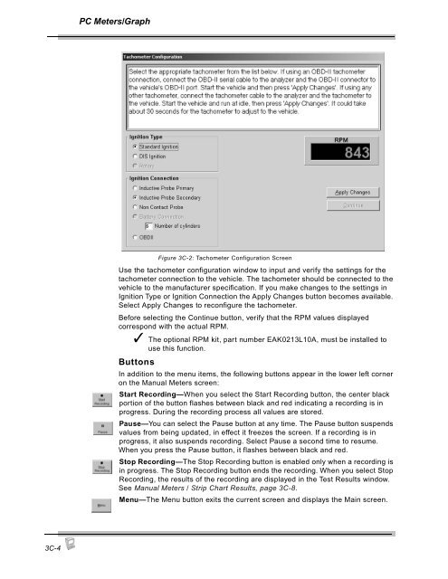
PC Meters/GraphUse the tachometer configuration window to input and verify the settings for thetachometer connection to the vehicle. The tachometer should be connected to thevehicle to the manufacturer specification. If you make changes to the settings inIgnition Type or Ignition Connection the Apply Changes button becomes available.Select Apply Changes to reconfigure the tachometer.Before selecting the Continue button, verify that the RPM values displayedcorrespond with the actual RPM.✓ The optional RPM kit, part number EAK0213L10A, must be installed touse this function.ButtonsFigure 3C-2: Tachometer Configuration ScreenIn addition to the menu items, the following buttons appear in the lower left corneron the Manual Meters screen:Start Recording—When you select the Start Recording button, the center blackportion of the button flashes between black and red indicating a recording is inprogress. During the recording process all values are stored.Pause—You can select the Pause button at any time. The Pause button suspendsvalues from being updated, in effect it freezes the screen. If a recording is inprogress, it also suspends recording. Select Pause a second time to resume.When you press the Pause button, it flashes between black and red.Stop Recording—The Stop Recording button is enabled only when a recording isin progress. The Stop Recording button ends the recording. When you select StopRecording, the results of the recording are displayed in the Test Results window.See Manual Meters / Strip Chart Results, page 3C-8.Menu—The Menu button exits the current screen and displays the Main screen.3C-4
PC Meters/GraphStrip ChartTo view the Strip Chart display,Press the Gas button and choose Strip Chart from the menu.✓ You can also toggle between Manual Meters and Strip Chart using theTest Actions menu.The analyzer performs a zero check and then displays the Strip Chart.✓ The probe must be out of the tailpipe.The Strip Chart screen displays emissions values in an active wave form.Figure 3C-3: Strip Chart ScreenThe Strip Chart screen contains three menus and a set of buttons:• Test Actions• Gas Bench• Tachometer• Buttons3C-5
- Page 61 and 62: 2FPocket PC ResultsTest ResultsThe
- Page 63 and 64: Pocket PC ResultsChange StandardsCu
- Page 65 and 66: Pocket PCMaintenance2GThis section
- Page 67 and 68: Pocket PC Maintenance6. Press OK to
- Page 69 and 70: Pocket PC MaintenanceIf the reading
- Page 71 and 72: Pocket PC Maintenance✓ Always mak
- Page 73 and 74: Pocket PC Maintenance3. Remove the
- Page 75 and 76: Pocket PC MaintenanceSetupThis sect
- Page 77 and 78: Pocket PC MaintenanceRPM/Temp Kit
- Page 79 and 80: Pocket PC MaintenanceTSI / Idle Set
- Page 81 and 82: Pocket PC MaintenanceStandardsThe S
- Page 83 and 84: Pocket PC MaintenanceFigure 2G-23:
- Page 85 and 86: Pocket PC MaintenanceBoard Diagnost
- Page 87 and 88: Pocket PC MaintenanceTo perform the
- Page 89 and 90: Pocket PC Maintenance7. Press the S
- Page 91 and 92: Pocket PC MaintenanceFigure 2G-34:
- Page 93 and 94: Pocket PC MaintenanceLow Out FlowTh
- Page 95 and 96: Pocket PCOther Functions2HAboutThis
- Page 97 and 98: 3Using FGA with the PCThe Flexible
- Page 99 and 100: 3APC Software OverviewThe PC versio
- Page 101 and 102: PC Software OverviewCommands 1-10Co
- Page 103 and 104: PC Software OverviewCommandsFigure
- Page 105 and 106: 3BPC SoftwareInstallationThe Flexib
- Page 107 and 108: PC Software Installation5. If this
- Page 109 and 110: 3CPC Meters/Strip ChartThis chapter
- Page 111: PC Meters/GraphGas Bench MenuThe Ga
- Page 115 and 116: PC Meters/GraphStrip Chart Display
- Page 117 and 118: PC Meters/GraphWhen you select the
- Page 119 and 120: PC Meters/GraphTachometerUse the Ta
- Page 121 and 122: PC Automatic Tests3DTSI TestThis se
- Page 123 and 124: PC Automatic TestsTachometer Config
- Page 125 and 126: PC Automatic TestsIdle RPM TestFGA
- Page 127 and 128: PC Automatic TestsTSI Results16. Th
- Page 129 and 130: 3EPC Customer/VehicleFGA is designe
- Page 131 and 132: PC Customer/VehicleInformation bar
- Page 133 and 134: PC Customer/VehicleWhen the desired
- Page 135 and 136: 3FPC ResultsThe Test Results window
- Page 137 and 138: 3GPC MaintenanceGas CalibrationThis
- Page 139 and 140: PC Maintenance5. Attach the calibra
- Page 141 and 142: PC MaintenanceNew NO x SensorNew NO
- Page 143 and 144: PC MaintenanceShop InformationThe S
- Page 145 and 146: PC MaintenanceThe Setup window cont
- Page 147 and 148: PC MaintenanceTSI Test SetupThe TSI
- Page 149 and 150: PC MaintenanceZero Purge Time(s)—
- Page 151 and 152: PC MaintenanceDiagnosticsService ut
- Page 153 and 154: PC Other Functions3HThis chapter co
- Page 155 and 156: 4General MaintenanceThis chapter ad
- Page 157 and 158: General MaintenanceOptionsPart Numb
- Page 159 and 160: General Maintenance3. Select the Ig
- Page 161 and 162: General MaintenanceWhen using the O
PC Meters/GraphUse the tachometer c<strong>on</strong>figurati<strong>on</strong> window to input and verify the settings for thetachometer c<strong>on</strong>necti<strong>on</strong> to the vehicle. The tachometer should be c<strong>on</strong>nected to thevehicle to the manufacturer specificati<strong>on</strong>. If you make changes to the settings inIgniti<strong>on</strong> Type or Igniti<strong>on</strong> C<strong>on</strong>necti<strong>on</strong> the Apply Changes butt<strong>on</strong> becomes available.Select Apply Changes to rec<strong>on</strong>figure the tachometer.Before selecting the C<strong>on</strong>tinue butt<strong>on</strong>, verify that the RPM values displayedcorresp<strong>on</strong>d with the actual RPM.✓ The opti<strong>on</strong>al RPM kit, part number EAK0213L10A, must be installed touse this functi<strong>on</strong>.Butt<strong>on</strong>sFigure 3C-2: Tachometer C<strong>on</strong>figurati<strong>on</strong> ScreenIn additi<strong>on</strong> to the menu items, the following butt<strong>on</strong>s appear in the lower left corner<strong>on</strong> the Manual Meters screen:Start Recording—When you select the Start Recording butt<strong>on</strong>, the center blackporti<strong>on</strong> of the butt<strong>on</strong> flashes between black and red indicating a recording is inprogress. During the recording process all values are stored.Pause—You can select the Pause butt<strong>on</strong> at any time. The Pause butt<strong>on</strong> suspendsvalues from being updated, in effect it freezes the screen. If a recording is inprogress, it also suspends recording. Select Pause a sec<strong>on</strong>d time to resume.When you press the Pause butt<strong>on</strong>, it flashes between black and red.Stop Recording—The Stop Recording butt<strong>on</strong> is enabled <strong>on</strong>ly when a recording isin progress. The Stop Recording butt<strong>on</strong> ends the recording. When you select StopRecording, the results of the recording are displayed in the Test Results window.See Manual Meters / Strip Chart Results, page 3C-8.Menu—The Menu butt<strong>on</strong> exits the current screen and displays the Main screen.3C-4


