

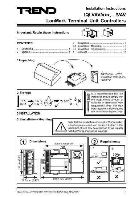
IQLVAV/xxx, ../VAV LonMark Terminal Unit Controllers Installation ...
IQLVAV/xxx, ../VAV LonMark Terminal Unit Controllers Installation ...
IQLVAV/xxx, ../VAV LonMark Terminal Unit Controllers Installation ...

Create successful ePaper yourself
Turn your PDF publications into a flip-book with our unique Google optimized e-Paper software.
920 16 D EI @ A L E? A ? F EA I M EJD 2 = HJ # BJD A + + 4 K A I F A H= JE EI I K > A ? JJ JD AB M E C ? @ EJE I 6 D EI @ A L E? A = O J? = K I A D = H BK E JA HBA HA ? A= @ JD EI @ A L E? A K I J= ? ? A F J= O E JA HBA HA ? AHA ? EA L A @ E ? K @ E CE JA HBA HA ? A JD = J = O ? = K I A K @ A I EHA @ F A H= JE 92 90 120 16 D EI @ A L E? A ? F EA I M EJD 2 = HJ # BJD A + + 4 K A I F A H= JE EI I K > A ? JJ JD AB M E C ? @ EJE I 6 D EI @ A L E? A = O J? = K I A D = H BK E JA HBA HA ? A= @ JD EI @ A L E? A K I J= ? ? A F J= O E JA HBA HA ? AHA ? EA L A @ E ? K @ E CE JA HBA HA ? A JD = J = O ? = K I A K @ A I EHA @ F A H= JE 6 D EI @ A L E? A ? F EA I M EJD 2 = HJ # BJD A + + 4 K A I F A H= JE EI I K > A ? JJ JD AB M E C ? @ EJE I 6 D EI @ A L E? A = O J? = K I A D = H BK E JA HBA HA ? A= @ JD EI @ A L E? A K I J= ? ? A F J= O E JA HBA HA ? AHA ? EA L A @ E ? K @ E CE JA HBA HA ? A JD = J = O ? = K I A K @ A I EHA @ F A H= JE <strong>Installation</strong> Instructions<strong>IQL<strong>VAV</strong></strong>/<strong>xxx</strong>, ../<strong>VAV</strong>3.1 <strong>Installation</strong> - Mounting (continued)h4Set Damper Limits (continued)ijIf the damper stops arechanged it may benecessary to change the<strong>VAV</strong> Damper driver fullscale drive time. Seesection 3.2 step 215Connect Differential Pressure SensorDuct8 ) 8 4.75 mm ( 3 / 16”)IDLow<strong>IQL<strong>VAV</strong></strong>High6Connect Input Powerterminal size 0.35 to 2.5 mm 2(14 to 22 AWG)Earth (ground) 24 Vacinput power neutral attransformerIQL consumption
920 16 D EI @ A L E? A ? F EA I M EJD 2 = HJ # BJD A + + 4 K A I F A H= JE EI I K > A ? JJ JD AB M E C ? @ EJE I 6 D EI @ A L E? A = O J? = K I A D = H BK E JA HBA HA ? A= @ JD EI @ A L E? A K I J= ? ? A F J= O E JA HBA HA ? AHA ? EA L A @ E ? K @ E CE JA HBA HA ? A JD = J = O ? = K I A K @ A I EHA @ F A H= JE <strong>IQL<strong>VAV</strong></strong>/<strong>xxx</strong>, ../<strong>VAV</strong><strong>Installation</strong> Instructions3.1 <strong>Installation</strong> - Mounting (continued)7Connect LonWorks (continued)Terminatore.g.LONTERMINATORLINCIQLROUTERTABIQLLONCSCN LonA LonB SCN LonALonB4 5 6 7 8 9 1011w x y zSCN LonA LonB SCN LonALonB100 F, 50 V minRecommend terminate atLINC or Router.e.g. use IQLRouter integralterminatorsMaximum 64 nodes per Lon segmentMaximum 40 IQLs (and LONCs) per Lan100 F, 50 V minNormal IQ System current loop Lan cableis not recommendedDo not use screened cableIQLROUTERTTAB4 5 6 7 8 9 1011wIQLx y zLONCSCN LonA LonB SCN LonALonB<strong>LonMark</strong>DeviceLINCLINCLonWorks busRecommended CablesMax bus lengthMax nodenode500 m (545B elden 85102500m (545 yds)yds)TrendTP/1/0/16/HF/200 500m (545 yds) 400 m (430 yds)(Belden 8471)U L Level IV, 22 AWG 500m (545 yds)400 m (430 yds)J Y(St) Y2 x 2 x 0.8 500m (545 yds)320 m (350 yds)T IA568A Cat. 5, 24 AWG 450m (490 yds)250 m (270 yds)toIQ System OutstationsIQ SystemOutstation<strong>Terminal</strong> size 0.35 to 2.5 mm 2 (14 to 22 AWG)If used with LPT-10 (powered bus), cable lengths differ - see “Link Power TransceiverUser’s Guide (078-0105-01C)”.8Connect Inputs and OutputsIf custom strategy, follow special installationinstructions and jump to section 3.2.Custom Strategy<strong>Installation</strong> Instructions9Connect InputsAlarm ContactPushbuttonoutput not available ! " # 8 ) & & 8 4 , 1 # #8 ) 8 $ 1 ""Local Setpoint AdjustmentPotentiometerSupply Air TemperatureSensor % &+ ' 1 !Local Space TemperatureSensorNOTE: see next section if connecting TB or RD1+ 1 !Cable size 0.35 to 2.5 mm 2 (14 to22 AWG) - Cu only4<strong>IQL<strong>VAV</strong></strong>/<strong>xxx</strong>, ../<strong>VAV</strong> <strong>Installation</strong> Instructions TG200704 Issue 2/D 22/08/07
920 16 D EI @ A L E? A ? F EA I M EJD 2 = HJ # BJD A + + 4 K A I F A H= JE EI I K > A ? JJ JD AB M E C ? @ EJE I 6 D EI @ A L E? A = O J? = K I A D = H BK E JA HBA HA ? A= @ JD EI @ A L E? A K I J= ? ? A F J= O E JA HBA HA ? AHA ? EA L A @ E ? K @ E CE JA HBA HA ? A JD = J = O ? = K I A K @ A I EHA @ F A H= JE <strong>Installation</strong> Instructions<strong>IQL<strong>VAV</strong></strong>/<strong>xxx</strong>, ../<strong>VAV</strong>3.1 <strong>Installation</strong> - Mounting (continued)10Connect IQ System SensorsRoom DisplayRD-IQL, room display connects using one input(IN5) and has options.RD-IQL/K: includes space temperaturesensor with setpoint adjustment. Itprecludes the use of occupation overridepush button (IN4) and alarm contact (IN5).RD/IQL/KOS: as for RD-IQL/K plusoccupation override push button andstatus display.If using RD-IQL, a separate thermistor sensorconnected to IN1 may be used if required (seesection 3.2 step 19)IQ System SensorsInputs can be provided by IQ System sensorTB/TS space temperature sensor:/K . plus potentiometer, /KE ..plus pushbutton-output notavailable#"! ! <strong>IQL<strong>VAV</strong></strong> 8 ) & & " 8 # $ 1 " % &4 , 1 #+ 1#"RD-IQL<strong>IQL<strong>VAV</strong></strong> " 8 6 * 6 5 ' 1 ! + 1 !polarity independent # 4 , 1 ##Note that <strong>IQL<strong>VAV</strong></strong> IN5 link and the <strong>IQL<strong>VAV</strong></strong> strategymust be correctly set up to use the RD-IQL, see3.2 steps 4, 5 and 1911Connect Triac Outputs24 Vac, 0.7 A max per output (must be added to input power requirement)0 9 5 8 = L AcommonLowerRaise , # #, ""8 ) 8 ! " - A ? JHE? 0 A = J5 J= C A " , !!- A ? JHE? 0 A = J5 J= C A # , $ " = % , cable size 0.35 to 2.5 mm 2 (14 to 22 AWG) - Cu only<strong>IQL<strong>VAV</strong></strong>/<strong>xxx</strong>, ../<strong>VAV</strong> <strong>Installation</strong> Instructions TG200704 Issue 2/D 22/08/07 5
1,5 A HE= ) 5 JH= JA C O 1,5 A HE= 9 52 90 126 D EI @ A L E? A ? F EA I M EJD 2 = HJ # BJD A + + 4 K A I F A H= JE EI I K > A ? JJ JD AB M E C ? @ EJE I 6 D EI @ A L E? A = O J? = K I A D = H BK E JA HBA HA ? A= @ JD EI @ A L E? A K I J= ? ? A F J= O E JA HBA HA ? AHA ? EA L A @ E ? K @ E CE JA HBA HA ? A JD = J = O ? = K I A K @ A I EHA @ F A H= JE 0 16 D EI @ A L E? A ? F EA I M EJD 2 = HJ # BJD A + + 4 K A I F A H= JE EI I K > A ? JJ JD AB M E C ? @ EJE I 6 D EI @ A L E? A = O J? = K I A D = H BK E JA HBA HA ? A= @ JD EI @ A L E? A K I J= ? ? A F J= O E JA HBA HA ? AHA ? EA L A @ E ? K @ E CE JA HBA HA ? A JD = J = O ? = K I A K @ A I EHA @ F A H= JE 1, ) # ! $ # 5 A HE= 13 N 9 4 " # # ) 511118 ) 8 920 1 96 D EI @ A L E? A ? F EA I M EJD 2 = HJ # BJD A + + 4 K A I F A H= JE EI I K > A ? JJ JD AB M E C ? @ EJE I 6 D EI @ A L E? A = O J? = K I A D = H BK E JA HBA HA ? A= @ JD EI @ A L E? A K I J= ? ? A F J= O E JA HBA HA ? AHA ? EA L A @ E ? K @ E CE JA HBA HA ? A JD = J = O ? = K I A K @ A I EHA @ F A H= JE 20 16 D EI @ A L E? A ? F EA I M EJD 2 = HJ # BJD A + + 4 K A I F A H= JE EI I K > A ? JJ JD AB M E C ? @ EJE I 6 D EI @ A L E? A = O J? = K I A D = H BK E JA HBA HA ? A= @ JD EI @ A L E? A K I J= ? ? A F J= O E JA HBA HA ? AHA ? EA L A @ E ? K @ E CE JA HBA HA ? A JD = J = O ? = K I A K @ A I EHA @ F A H= JE <strong>IQL<strong>VAV</strong></strong>/<strong>xxx</strong>, ../<strong>VAV</strong><strong>Installation</strong> Instructions3.2 <strong>Installation</strong> - Configuration1Switch off2Isolate I/O1WARNING:The connectingleads may beconnected tosupplies. Isolate before touching.8 ) 8 3 Remove CoverCheck Bus LinkS position (default)8 ) 8 4AJ6SAJ6S5Set up IN5 link if using RD-IQL (see section 3.1. step 10)RD 1 5J5I5Note default position(if not using RD-IQL)RD 1 5J5RDJ56 Replace Cover7Reconnect I/O 8Tear off Label Strip‘locate’9Switch On8 ) 8 1, 00:A0:25:36:51:005 A HE= IQL1xWR4_50100025 ) 117 5 0275 JH= JA C O IQL1x WR4 E 06 1, 00:A0:25:36:51:005 A HE= IQL1xWR4_5010002516<strong>IQL<strong>VAV</strong></strong>/<strong>xxx</strong>, ../<strong>VAV</strong> <strong>Installation</strong> Instructions TG200704 Issue 2/D 22/08/07
920 1 96 D EI @ A L E? A ? F EA I M EJD 2 = HJ # BJD A + + 4 K A I F A H= JE EI I K > A ? JJ JD AB M E C ? @ EJE I 6 D EI @ A L E? A = O J? = K I A D = H BK E JA HBA HA ? A= @ JD EI @ A L E? A K I J= ? ? A F J= O E JA HBA HA ? AHA ? EA L A @ E ? K @ E CE JA HBA HA ? A JD = J = O ? = K I A K @ A I EHA @ F A H= JE 20 16 D EI @ A L E? A ? F EA I M EJD 2 = HJ # BJD A + + 4 K A I F A H= JE EI I K > A ? JJ JD AB M E C ? @ EJE I 6 D EI @ A L E? A = O J? = K I A D = H BK E JA HBA HA ? A= @ JD EI @ A L E? A K I J= ? ? A F J= O E JA HBA HA ? AHA ? EA L A @ E ? K @ E CE JA HBA HA ? A JD = J = O ? = K I A K @ A I EHA @ F A H= JE <strong>Installation</strong> Instructions<strong>IQL<strong>VAV</strong></strong>/<strong>xxx</strong>, ../<strong>VAV</strong>3.2 <strong>Installation</strong> - Configuration (continued)17Check Operation - Pushbutton Input8 ) 8 Parallel fan (W2=0) used for heatingonly. Serial fan (W2=1) on constantduring occupation, cooling only duringnon-occupationIf FanSpeedAutoW3=0DO2, 3IN4DO1fan onDO6,7Electric heaters or HWS valve selected by configuration parameter W3 orDO4, 5W3=1 heaters on18Check Operation - Local SP Adjust8 ) 8 Parallel fan (W2=0) used for heatingonly. Serial fan (W2=1) on constantduring occupation, cooling only duringnon-occupationElectric heaters or HWS valveselected by configurationparameter W3IN2DO1DO6, 7W3=0DO2, 3W3=1DO4, 5 or Wait 6 secs at each end to calibrate potentiometer<strong>IQL<strong>VAV</strong></strong>/<strong>xxx</strong>, ../<strong>VAV</strong> <strong>Installation</strong> Instructions TG200704 Issue 2/D 22/08/07 9
<strong>IQL<strong>VAV</strong></strong>/<strong>xxx</strong>, ../<strong>VAV</strong><strong>Installation</strong> Instructions3.2 <strong>Installation</strong> - Configuration (continued)19Set up Strategy Parameters Use IqlTool2 (see section 3.2 step 12) and textif required communicationsParameter Label Function DefaultK1(V) Remote Setpoint Base setpoint can be adjusted remotely 20 °CK2(V) RemoteSpace Temp Used if bound to Lon sensor, or if local sensor disconnected 20 °CK3(V) OCC Deadbnd Deadband around setpoint during Occ 1 °CK4(V) Standby Deadbnd Deadband around setpoint during Standby 2 °CK5(V) NOCC Deadbnd Deadband around setpoint during Nocc 12 °CK6(V) Remote Occ Sets state 0=Occ, 1=Nocc, 2=Bypass, 3=Standby 0=OccupiedK11(V) Htng Air Flow SP Airflow used when heating 50 lpsK12(V) k constant Box constant converts square root diff. press. to volume flow 1K13(V) Min Airflow SP Minimum airflow permitted by <strong>VAV</strong> damper 50 lpsK14(V) Max Airflow SP Maximum airflow permitted by <strong>VAV</strong> damper 300 lpsK15(V) Offset Range Defines range of Local SP adjust pot. 2 °CK16(V) Damper Position Sets damper position if W16=1 10 %W1(S) Boost Mode Set to 1 for Boost Mode - drives into Occ, with Max. Volume 0=normalW2(S) Serial Fan En Overrides the fan on during occupation 0=fan normalW3(S) Elec Disable Disables electric heaters and enables HWS valve if set to 1 0=enable heatersW8(S) Remote Shutdown Shuts off fan, closes damper, swtiches off heaters 0=no shutdownW15(S) DevAlmEnable Enables loop deviation alarms 0=alarms disabledW16(S) Damper Override Sets damper position to K16 0=damper in autoL1(G) Heat Loop Gain 20L1(I) Heat Loop Integral 0 minsL2(G) Cool Loop Gain -20L2(I) Cool Loop Integral 0 minsL3(G) Damper Loop Gain It is recommended to leave gain at zero (integral only) 0L3(I) Damper Loop Integral See step 24 below 3 minsNote that any changes to the strategy parameters should immediately be followed by a write to theaddress module, [text comms command, R(z=0), recommended], to commit changes to flash memory.-If used with RD-IQL (see section 3.1 step 10), the following must be configured: Local Space TempType S9(Y=6), Local SP Adjust Type S10(Y=6) followed by R(z=1) to write changes to flash andreset. Configuration for RD-IQL is facilitated by IqlTool2. If the sensor on IN1 is to be used, leaveLocal Space Temp type at default, S9(Y=1).-Enabling loop deviation alarms using W15 requires the 3 loops’ deviation limits (Ln(V)) to be set up,otherwise the alarms will be generated for small changes in process variable.2021Calibrate Differential Pressor SensorSet K12, to <strong>VAV</strong> box manufacturer’s box constant or measure volume flow rate (/<strong>VAV</strong>=lps, /<strong>VAV</strong>/USA=CFM) using calibrated instrument and adjust K12 so that S8 (Actual Air flow) gives correctvalue. (Ensure zero offset is calibrated before calibrating the differential pressure sensor, seesection 3.2 step 14).Set Damper Actuator Drive TimeIf the damper stops have been changed (see 3.1 step 4)Change the <strong>VAV</strong> Damper driver full scale drive time set by the strategy, parameter D5(D).The time should be measured in seconds from fully closed to fully open and the parameterchanged if necessary using text communications i.e. D5(D=x).Tune Damper Control Loop22 <strong>IQL<strong>VAV</strong></strong>/<strong>VAV</strong> Data SheetTune the damper control loop (L3) asTA200750desribed in <strong>IQL<strong>VAV</strong></strong>/<strong>VAV</strong> data sheet.10<strong>IQL<strong>VAV</strong></strong>/<strong>xxx</strong>, ../<strong>VAV</strong> <strong>Installation</strong> Instructions TG200704 Issue 2/D 22/08/07
<strong>Installation</strong> Instructions<strong>IQL<strong>VAV</strong></strong>/<strong>xxx</strong>, ../<strong>VAV</strong>3.2 <strong>Installation</strong> - Configuration (continued)Set up System Core Firmware Module Parameters23 if required - see conditionsUsing IqlTool2 (see section 3.2 step 12) and text communicationsParameterSettingFunctionConditionNoteR(..addressT(..TimeU1(..UserL - own addressdeviceaddress of IQLif required to rearrangeLans, address1, 2,4N - own LaNLannumber of IQLif required to rearrange1, 2Lans, addressD - identifieridentifierattribute of IQLFor alarm ident, text1comms, IC commsF - attribute 2textcomms attributesFortext comms, IC comms1G - attribute 31A - own Lan alarm addressaddress and Lan of ownto report Lan alarms to a 1R - Own Lan alarm LanLan alarm target supervisor1E - Internetwork alarmaddress and Lan of to report internetwork1addressInternetwork alarm alarms to a supervisor (onlyT - Internetwork alarm Lantargetfor lowest addressed IQSystem device on Lan)1r - LonWorks retry timei - LonWorks interpacketdelaySee IQ System LonWorksProducts EngineeringManual for detailsa - LonWorks service class2b - router Buffer sizem - LonWorkscodeMessageg - generator numbere - neuron idH - HoursN - MinutesD - Day of monthbuffer size(bytes)Default = 146code number.Default = 64uniqueidentifier forneuronspecifies smallest routerbuffer on systemCode used byIQLs/LINCs/LONCs, allLINCs/LONCs must usesame codeT o find PIN if lost(read only)To find PIN if lost; toidentify Lon nodeCurrenttimeCurrentdateIf routers separateIQLs/LINCs/LONCs andhave buffer size smaller that146 bytes - set to smallestbuffer size. (minimum = 66)If message code being usedby other users - must beexclusive to IQ System(read only)To synchronise time foralarms and loggingTo synchronise date foralarms and loggingM - Month3Y - Year3l - Lan of systemtimemasterP - PINl -levelIQL timekeeper getstime sync from IQ ataddress 11 on this LanPIN number in IQauthoritylevel of PINIQL will be timekeeper If this'l'parameter is non-zeroand own address = 11To protect fromunauthorised changesNote 1: IqlTool2 facilitates setting of these parameters across the Lon segmentNote 2: Changing any of these parameters results in a controller reset (clears down time and and sensor logs)Note 3: Any changes to these parameters should immediately be followed by a write to the addressmodule, [text comms command, R(z=0), recommended], to commit changes to flash memory.Note 4: IqlTool2 facilitates setting to timekeeper (sets up timemaster Lan and changes own address to 11)Note 5: Message code can only be changed by text comms if 'lonworks managed' (read only) is set to No.Note 6: If PIN is forgotten see note in section 3.2 step 12.2222, 533, 43, 6Noprotection if zero324Set up Lan Systemif requiredCheck LanSETLonWorksLINCIQUse SET and terse text communicationsLINC <strong>Installation</strong>Instructions - TG103062IQ System LonWorksProducts EngineeringManual TE200292<strong>IQL<strong>VAV</strong></strong>/<strong>xxx</strong>, ../<strong>VAV</strong> <strong>Installation</strong> Instructions TG200704 Issue 2/D 22/08/07 11
<strong>IQL<strong>VAV</strong></strong>/<strong>xxx</strong>, ../<strong>VAV</strong><strong>Installation</strong> Instructions3.2 <strong>Installation</strong> - Configuration (continued)25Set up IC Comms from IQLif requiredUse IqlTool2 (see section 3.2 step 12) and text communicationsIC Comms Module Nx(.. - (x=1 to y; y=4 for standard strategies)ParameterFunctionA - Remote device addressIf zero, 'global to' comms. If non-zero specifiestarget device address for 'data to' commsFor 'global to' comms only, attribute of target IQ,B - Attributereferences attribute in address module (0 'noattribute', - all IQs on Lan,1 'identifier', 2 'attribute2', 3 'attribute 3')N - Remote LanTarget IQ Lan number; if Lan zero, address zero,specifies global globalI - IntervalInterval between sending (minutes)S - Significant change Amount analogue must change before sendingM - Source item string Item and parameter being sent (e.g. S1(V) )E - Destination module number No. of destination module receiving IC commsT - Destination typeType of destn module receiving comms (e.g. W,K)LonWorksLCI<strong>IQL<strong>VAV</strong></strong>S1S8K1K2K8I1I8W1W7W8NxNxIC CommsLINCIQ26IC Comms ‘direction’ in IQ must be:Global To, Min, Max, Sum, or Average(directions 2 to 6)LonWorksSet up IC Comms from IQif requiredsee IQ ConfigurationManual 90-1533Use PowerTool or Wupdn and terse textcommunications27LonWorksSet up Text Communicationsfrom Supervisorif requirede.g. 963 (drag and dropvalues)Note that standard strategy pagesare available for 963 from Partnernet<strong>IQL<strong>VAV</strong></strong>S1Terse Text CommsLINC4 Disposal<strong>IQL<strong>VAV</strong></strong>S1S16A1A16K1 A17K8 A24I1 B1,0I16 B2,7W1 B18,0W8 B19,7LINCNxNxIQIC CommsWEEE Directive :K1K2K8I1S8I8W1W7W8IQNote that any changesto the strategyparameters shouldimmediately befollowed by a write tothe address module, [text comms command, R(z=0),recommended], to commit changes to flash memory.At the end of their useful life the packagin and product should be disposed ofby a suitable recycling centre.Do not dispose of with normal household waste. Do not burn.Manufactured for and on behalf of the Environmental and Combustion Controls Division of Honeywell Technologies Sàrl, Ecublens, Routedu Bois 37,Switzerland by its Authorized Representative, Trend Control Systems Limited.Trend Control Systems Limited reserves the right to revise this publication from time to time and make changes to the content hereofwithout obligation to notify any person of such revisions or changes.Trend Control Systems LimitedP.O. Box 34, Horsham, West Sussex, RH12 2YF, UK. Tel:+44 (0)1403 21888 Fax:+44 (0)1403 241608 www.trend-controls.comTrend Control Systems USA6670 185th Avenue NE, Redmond, Washington 98052, USA. Tel: (425)897-3900, Fax: (425)869-8445 www.trend-controls.com12<strong>IQL<strong>VAV</strong></strong>/<strong>xxx</strong>, ../<strong>VAV</strong> <strong>Installation</strong> Instructions TG200704 Issue 2/D 22/08/07


