evaluation of overheating protection with sun-shading systems
evaluation of overheating protection with sun-shading systems
evaluation of overheating protection with sun-shading systems

Create successful ePaper yourself
Turn your PDF publications into a flip-book with our unique Google optimized e-Paper software.
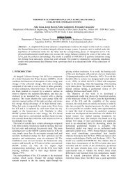
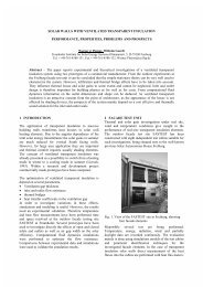
EVALUATION OFOVERHEATING PROTECTION WITHSUN-SHADING SYSTEMSTilmann E. Kuhn and Werner J. PlatzerDept. Thermal and Optical Systems, Fraunh<strong>of</strong>er Institute for Solar Energy Systems ISE, Oltmannsstr. 5, D-79100Freiburg, Germany, Phone: ++49 (0)761/ 4588-297, Fax: ++49 (0)761/4588-132, tilmann.kuhn@ise.fhg.deAbstract – Sun-<strong>shading</strong> <strong>systems</strong> have to provide thermal and visual comfort reliably and economically.At the same time, they should prevent unwanted solar gains in summer and permit high solar gains inwinter. This paper describes a method for the assessment <strong>of</strong> the heat barrier effect <strong>of</strong> different types <strong>of</strong><strong>sun</strong>-<strong>shading</strong> <strong>systems</strong> together <strong>with</strong> the associated control strategy.The starting point for the performance assessment is adequate characterization, appropriate to the size andcomplexity <strong>of</strong> the facade <strong>of</strong> the assessed building. The thermal characterization consists <strong>of</strong> the angledependentdetermination <strong>of</strong> the Total Solar Energy Transmittance g <strong>with</strong> a calculation method, which isvalidated <strong>with</strong> calorimetric measurements. The combination <strong>with</strong> typical irradiance distributions allowsthe <strong>evaluation</strong> <strong>of</strong> different control strategies. This paper shows that it is essential for the reliability <strong>of</strong> thecalculated cooling and heating loads, that this calculation is based on a control strategy, that fits <strong>with</strong> thepriorities <strong>of</strong> the building users.1. INTRODUCTIONOptimal use <strong>of</strong> daylight and solar heat gains in buildingsis made possible by the use <strong>of</strong> good <strong>sun</strong>-<strong>shading</strong> <strong>systems</strong>.This means that <strong>sun</strong>-<strong>shading</strong> <strong>systems</strong> must be able tocontrol and regulate solar gains through facades. Atpresent, there are no reliable standard methods for the<strong>evaluation</strong> <strong>of</strong> the effectiveness <strong>of</strong> <strong>sun</strong>-<strong>shading</strong> <strong>systems</strong>.This means that architects and building designers have tomake their own decision on the methodology. Frequently,this decision is wrong, as we know from buildings <strong>with</strong><strong>overheating</strong> problems in summer. In some <strong>of</strong> these cases,the Fraunh<strong>of</strong>er ISE made studies in order to detect theerror. The most frequent problem in our experience is thatpeople do not want to use the <strong>shading</strong> <strong>systems</strong> in the waythey are planned to be used. One example: In many casesbuilding designers assume that people are willing to closethe slats <strong>of</strong> venetian blinds in summer, which is not truein most cases. The demands <strong>of</strong> the future users <strong>of</strong> thebuilding have to be taken into account in an early stage <strong>of</strong>the planning process! The effectiveness <strong>of</strong> a <strong>sun</strong>-<strong>shading</strong>system has to be assessed <strong>with</strong> methods that are able totake the various demands into account. This means thatthe planning team <strong>of</strong> a building has to agree on a controlstrategy that fits <strong>with</strong> the priorities <strong>of</strong> the future users.We developed a methodology to assess the effectiveness<strong>of</strong> a <strong>sun</strong>-<strong>shading</strong> system together <strong>with</strong> the associatedcontrol strategy. The methodology has been validated<strong>with</strong> internal and external venetian blinds supplied by thecompany Hüppe Form, Oldenburg, Germany. The nextsection is a discussion <strong>of</strong> the requirements <strong>of</strong> users. Apresentation <strong>of</strong> the methodology then follows.2. USER REQUIREMENTSrequirementson<strong>sun</strong><strong>shading</strong><strong>systems</strong>Figure 1: User requirements.thermal requirementsdaylighting andoptical requirementslow costshigh reliabilityaesthetic requirementscompliance <strong>with</strong> technicalboundary conditions(mounting dimensions, dimensionswhen the blind is fully retracted,...)<strong>protection</strong> againstfire, noise, weatherFigure 1 gives an overview <strong>of</strong> the requirements for <strong>sun</strong><strong>shading</strong><strong>systems</strong>. The most important factors for thebehaviour <strong>of</strong> users are the thermal and daylightingrequirements.Figure 2 specifies thermal and optical requirements indetail. It should be recognized that it is impossible tooptimize all criteria simultaneously. It is alwaysnecessary to find the compromise that best matches the..
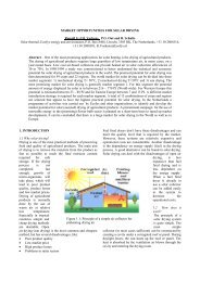
priorities <strong>of</strong> the user. Three examples shall demonstratethis:1 For many <strong>systems</strong>, good visual contact to theexterior is only possible <strong>with</strong> reduced heat<strong>protection</strong>.2 In many cases, a sufficient supply <strong>of</strong> daylight isonly possible <strong>with</strong> reduced heat <strong>protection</strong>.3 The winter solar gains are reduced, when <strong>shading</strong><strong>systems</strong> are used for glare <strong>protection</strong>.thermalrequirementsdaylightingand opticalrequirementsFigure 2: Daylighting and thermal requirementshigh solar gains in winterlow solar gains in summerand high thermal comfortsufficient supply<strong>of</strong> daylighthomogenous illumination<strong>of</strong> the roomglare <strong>protection</strong>privacy <strong>protection</strong>optional room darkeningvisual contact to exteriorpleasant color impression3. g-VALUE AS A MEASURE FOR SOLAR GAINS3.1 The meaning <strong>of</strong> gTo assess the heat barrier effect <strong>of</strong> <strong>shading</strong> <strong>systems</strong>, acharacteristic number is needed which quantifies the solarthermal gains through facades: The total solar energytransmittance g. The g value specifies the total fraction <strong>of</strong>incident solar energy which is transmitted through abuilding component. The transmitted energy fractionconsists <strong>of</strong> two parts: The solar transmittance and thesecondary internal heat transfer factor q i .heat100%reflection00000 11111111110000000000 1111111111 00000roller blind11111 00000glazing0000 11111111 00000000 11111111 00000000 11111111 000010 %absorption20 %heattransmittanceg-value= 0.2 ) (q i( τ e = 0.1 )Figure 3: The meaning <strong>of</strong> the total solar energy transmittance g(g = 0.3)Figure 3 illustrates the meaning <strong>of</strong> g for the example <strong>of</strong>an internal roller blind. In this case, a g value <strong>of</strong> 0.3means that 30% <strong>of</strong> the incident radiation is transmittedinto the building. The following factors influence theeffectiveness <strong>of</strong> blinds and shutters, the exact value <strong>of</strong> gdepends on these boundary conditions:.• The position <strong>of</strong> the blind (internal, integrated orexternal).• g depends on the glazing and the blind. Inparticular the effectiveness <strong>of</strong> internal blinds ishigher, if they are mounted behind a solar controlglazing, instead <strong>of</strong> a glazing <strong>with</strong> the heat mirroron the outer surface <strong>of</strong> the inner pane (heat mirrorglazing). The reason is that in the first case, thereflected radiation from the blind is mainlyabsorbed in the outer pane. In the second case it ismainly absorbed in the inner pane.• The wind conditions.• The ventilation <strong>of</strong> the gaps.• The direction <strong>of</strong> the incident irradiation.Especially the last point is commonly neglected or nottreated correctly during cooling load calculations. It isimportant to note that the g value can be higher foroblique angles <strong>of</strong> incidence. This is very <strong>of</strong>ten the case<strong>with</strong> blinds made <strong>of</strong> slats that can be tilted and controlstrategies <strong>with</strong> variable tilt angles <strong>of</strong> the slats. This meansthat the angular dependence <strong>of</strong> g must be taken intoaccount.3.2 Methods for the determination <strong>of</strong> gThere are two fundamentally different methods to determineg:• direct calorimetric measurementIn this procedure a segment <strong>of</strong> the real facade (e.g.1m 2 glazing plus blind <strong>with</strong>out the frame andsurrounding support structure) is measureddirectly. This is done by irradiating the sampleeither <strong>with</strong> <strong>sun</strong>light or a solar simulator. Behindthe facade, the transmitted energy is determinedcalorimetrically.For a detailed discussion see [Platzer et. al. 1997]or [Platzer 2000]• calculation methodsThe starting point <strong>of</strong> this method is thedetermination <strong>of</strong> the optical properties <strong>of</strong> thedifferent layers <strong>of</strong> the facade (e.g. transmittance,reflectance and absorptance <strong>of</strong> a venetian blind<strong>with</strong> a defined tilt angle <strong>of</strong> the slats). These fundamentalproperties can be determined by opticalmeasurements or <strong>with</strong> additional calculations bywhich the overall properties <strong>of</strong> the layers arecalculated from the material properties.The second step is the calculation <strong>of</strong> the solardirect-hemispherical transmittance τ e <strong>of</strong> the wholesystem and the absorptance in each <strong>of</strong> the layers.The last step is the calculation <strong>of</strong> q i , the inwardflowing fraction <strong>of</strong> the overall absorbed energy.The sum <strong>of</strong> τ e and q i equals g.
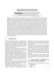
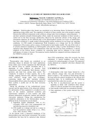
Comparative discussion <strong>of</strong> the two methods:Advantages <strong>of</strong> the calorimetric measurement:• Direct measurement <strong>with</strong>out model assumptions.This means that it is a reliable method.• No modeling necessary. This means, that thismethod is quicker for complex configurations.• Since real samples are assessed, deviations fromthe ideal properties <strong>of</strong> the samples are included inthe result (e.g. unequally tilted slats).Disadvantages <strong>of</strong> the calorimetric measurement:• Many time-consuming measurements are requiredto cover all the required combinations <strong>of</strong> glazingand blind <strong>with</strong> the defined operation modes andangles <strong>of</strong> incidence.• A sample <strong>of</strong> the facade has to be constructed andsent to the laboratory.Advantages <strong>of</strong> the calculation methods:• When the model has been prepared, the effect <strong>of</strong>modifications can be assessed quickly and easily.(e.g. different tilt angle or color <strong>of</strong> the slats)• No samples <strong>of</strong> the whole facade segment arerequiredDisadvantages <strong>of</strong> the calculation methods:• Validation <strong>with</strong> calorimetric measurement is mandatory.• At present there are no standards or draft standardswhich consider the angular dependence <strong>of</strong> g.3.3 Description <strong>of</strong> the chosen methodThe Fraunh<strong>of</strong>er Institute for Solar Energy Systems ISEcompared different calculation methods <strong>with</strong> calorimetricmeasurements for the company Hüppe Form, Germany.Together <strong>with</strong> the R+D department <strong>of</strong> this company, wehave chosen a practical method that is accurate, but nottoo costly. In this calculation method, the characterization<strong>of</strong> the optical properties <strong>of</strong> the venetian blinds is done<strong>with</strong> ray-tracing methods. The physical mechanismsconsidered during the ray-tracing process are shown infigure 4.The results <strong>of</strong> the ray-tracing process are the opticalproperties (reflectance, absorptance and transmittance) <strong>of</strong>a venetian blind for variable tilt angles <strong>of</strong> the slats andvariable directions <strong>of</strong> the incident irradiation. The basis <strong>of</strong>the method is a geometrical model <strong>of</strong> the blind, whichdescribes the form <strong>of</strong> the slats, the distance between theslats and possibly existing perforated regions <strong>of</strong> the slats.The optical properties <strong>of</strong> the individual slats aredetermined in a measurement. The next step is acomputer simulation <strong>of</strong> an optical measurement, whichmeans that many virtual light particles (photons) areincident on the blind <strong>with</strong> a defined direction. The<strong>evaluation</strong> <strong>of</strong> this virtual experiment is to count thereflected and the transmitted photons. The ratio <strong>of</strong> thereflected or transmitted photons to the incident photons isthe reflectance or transmittance respectively.incidentphotonsrollformed slat80 mmabsorptionscatteringglossysurface72 mmFigure 4: Schematic drawing <strong>of</strong> the mechanisms, considered in the raytracingmethod3.4 Validation <strong>of</strong> the methodThe accuracy <strong>of</strong> the method has been assessed for twodifferent internal venetian blinds and one externalvenetian blind. The following <strong>systems</strong> were provided tous by the manufacturer Hüppe Form, Oldenburg,Germany:• External venetian blind <strong>with</strong> metallic light grey slats.The width <strong>of</strong> the slats is 80 mm, the vertical distancebetween the slats 72 mm. The slats are rollformedand convex (edges curved downwards). A schematicdrawing <strong>of</strong> the slats is shown in figure 4.• Internal venetian blind <strong>with</strong> white slats. The width <strong>of</strong>the slats is 25 mm, the vertical distance between theslats is 20 mm. The slats are convex and perforated,except for an 8 mm broad area in the middle <strong>of</strong> eachslat. »Perforated« means that there are many smallholes in the slat. The transmittance <strong>of</strong> the perforatedarea was 7.7%.• Internal »daylighting« venetian blind. The slats areconcave (edges curved upwards), the upper side iscoated <strong>with</strong> a mirror foil, the lower side is paintedmatt light gray. The width <strong>of</strong> the slats is 25 mm, thevertical distance between the slats 20 mm. The slatsare convex and perforated, except for an 8 mm broadarea in the middle <strong>of</strong> each slat. The transmittance <strong>of</strong>the perforated area was 7.7%.
Table 1: Internal white venetian blind 25 mm (perforated) in combination<strong>with</strong> heat-mirror double glazed unit (DGU) K-Plus S (g DGU = 0.67,U DGU = 1.5 W/(m 2 K)). Tilt angle 0° means that the slats are in ahorizontal position.altitudeangleazimuthangletilt angle<strong>of</strong> theslatsg valuecalorimetricallymeasuredg Model(calculated)relativedeviation0 0 63° 0.42 0.41 -3%0 45 63° 0.41 0.40 -3%0 60 63° 0.36 0.38 7%0 0 closed(79°)0.34 0.35 1%45 0 0° 0.50 0.47 -5%60 0 0° 0.43 0.42 0%60 0 closed 0.32 0.33 1%Table 2: Internal »daylighting« venetian blind (perforated) incombination <strong>with</strong> heat-mirror glazing K-Plus S (g DGU = 0.67, U DGU = 1.5W/(m 2 K)).altitudeangleazimuthangletilt angle<strong>of</strong> theslatsg-valuecalorimetricallymeasuredg Model(calculated)relativedeviation0 0 63° 0.34 0.39 15%0 45 63° 0.38 0.39 3%0 60 63° 0.39 0.37 -5%0 0 closed(77°)0.35 0.29 -17%45 0 0° 0.60 0.62 3%60 0 0° 0.56 0.57 1%60 0 closed 0.30 0.29 -2%Table 3: External venetian blind pearl-silver 80 mm (not perforated) incombination <strong>with</strong> heat <strong>protection</strong> glazing K-Plus S (g DGU = 0.67, U DGU =1.5 W/(m 2 K)).altitudeangleazimuthangletilt angle<strong>of</strong> theslats0 0 closed(73°)g-valuecalorimetricallymeasuredg Model(calculated)0.02 0.050 45 closed 0.03 0.050 60 closed 0.03 0.0545 0 0° 0.09 0.1360 0 0° 0.04 0.0860 0 closed 0.01 0.04For the validation measurements, the blinds werecombined <strong>with</strong> a heat-mirror glazing manufactured byPilkington. The product name <strong>of</strong> the glazing is K-Plus S.The comparison between measured and calculated gvalues is shown in table 1-3. For the case <strong>of</strong> the internalwhite venetian blind, one can see the excellent agreementbetween measured and calculated values (table 1).For the »daylight« venetian blind, we found in principlethe same very good agreement. There are two exceptions:The first and the fourth measurement. In the first case themeasurement is difficult, because <strong>of</strong> the strong dependence<strong>of</strong> g on the tilt angle <strong>of</strong> the slats.(In this case theslats are closed 8° more than cut-<strong>of</strong>f 1 ). In the fourth casewe assume that the blind was not always closed exactly inthe same way.The calculated results for the external venetian blinds arealways slightly higher than the measured values.Concerning the heat barrier effect, the calculated valuesare on the safe side. The absolute difference (around 0.3)is sufficiently small.The results <strong>of</strong> this section can be summarized <strong>with</strong> thefollowing statements: The results <strong>of</strong> the calculationmethod have been validated <strong>with</strong> three very differenttypes <strong>of</strong> blinds and different combinations <strong>of</strong> altitude andazimuth angle. For these validation measurements, theblinds have been combined <strong>with</strong> a heat <strong>protection</strong>glazing. The agreement between modeled andcalorimetrically measured values is very good.4. MODELING OF THE SKY RADIANCEThe angle-dependent g value is not sufficient for the<strong>evaluation</strong> <strong>of</strong> the heat barrier effect <strong>of</strong> <strong>sun</strong>-<strong>shading</strong><strong>systems</strong> for two reasons: Most <strong>of</strong> the control strategiesfor venetian blinds use variable tilt angles <strong>of</strong> the slats<strong>with</strong> the tilt angle depending on the actual position <strong>of</strong> the<strong>sun</strong>. In addition, the angular distribution <strong>of</strong> the irradiationhas to be considered. This means, that it is necessary totake into account typical weather and irradiation data forthe location <strong>of</strong> the building. In our calculations this wasdone on the basis <strong>of</strong> hourly direct horizontal and diffusehorizontal irradiance data taken from the respective TestReference Year (TRY) [Blümel et. al., 1986]. The skyradiance distribution was calculated using the Perezmodel [Perez et. al., 1990 ], [Perez et. al., 1993]. Thecontinuous radiance distribution <strong>of</strong> the diffuse sky wasdiscretized by splitting it into 145 circular angularpatches <strong>with</strong> cone openings <strong>of</strong> 11.15° according toTregenza [Tregenza, 1987]. The ground was assumed tobe an isotropic diffuse reflector <strong>with</strong> an albedo <strong>of</strong> 0.2.The ground surface was divided into 90 discrete patches.Direct irradiation was treated as a parallel beam. Thedirection <strong>of</strong> the beam was calculated from the geogra-1 The slat position »Cut-Off« depends on the direction <strong>of</strong> the irradiance.In this position the slats are opend as wide as possible <strong>with</strong>out lettingthe <strong>sun</strong> shining directly through the blind.
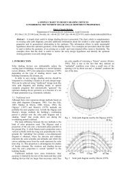
phical position, date and time. For the calculation <strong>of</strong> thisradiance distribution a modified version <strong>of</strong> the programgendaylit has been used [Reinhart et al. 2000].5. ASSESSMENT OF THE HEAT BARRIERFUNCTIONALITY OF BLINDS TOGETHER WITHTHE ASSOCIATED CONTROL STRATEGY5.1 Control strategiesIn the following, we demonstrate the new methodologyfor the case <strong>of</strong> an external venetian blind <strong>with</strong> white slatsin combination <strong>with</strong> heat <strong>protection</strong> glazing (Interpaneiplus neutral R, U DGU = 1.2 W/(m 2 K), g DGU = 0.60). Theslat width and slat geometry <strong>of</strong> the venetian blind isshown in figure 4. The starting point <strong>of</strong> the performanceassessment is the decision about the control strategy. Asstated above, this decision should be made together <strong>with</strong>the client and – if possible - the future user. This meansthat we are not able to define a general control strategy asa basis <strong>of</strong> the assessment. Instead <strong>of</strong> trying to do this, wewant to assess the performance <strong>of</strong> the system for two verydifferent control strategies.1 Strategy »closed«With this strategy, the slats are always closed totally,when the facade is irradiated directly by the <strong>sun</strong>. Theblind is fully retracted, when the facade is in theshade or when there is no direct illumination. For agiven combination <strong>of</strong> blind and glazing, this controlstrategy maximizes the <strong>overheating</strong> <strong>protection</strong> andglare <strong>protection</strong> 2 when the <strong>sun</strong> hits the facadedirectly. This control strategy ignores the need forvisual contact to the exterior. The dimensions <strong>of</strong> theroom and the windows will determine whether thesupply <strong>of</strong> daylight is sufficient or not.2 Strategy »cut-<strong>of</strong>f«As for the first strategy, the blind is fully retracted,when the facade is in the shade or when there is nodirect illumination. When the <strong>sun</strong> is shining directlyon the facade, the slats are tilted into the cut-<strong>of</strong>fposition.The slat position »cut-<strong>of</strong>f« depends on theactual position <strong>of</strong> the <strong>sun</strong>. In this position, the slatsare opened as far as possible <strong>with</strong>out letting the <strong>sun</strong>shine directly through the blind.This control strategy eliminates glare caused bydirect irradiation from the <strong>sun</strong> 2 and it ensures somekind <strong>of</strong> minimum <strong>overheating</strong> <strong>protection</strong>. AnAdvantage is the visible contact to the exteriorbecause <strong>of</strong> the opened slats, at least for higherpositions <strong>of</strong> the <strong>sun</strong>. Because <strong>of</strong> the <strong>protection</strong> <strong>of</strong> theroom from direct irradiation, the strategy ensures,that there are no directly lit stripes on desks orworkbenches. This means, that it elmininates veryuneven illumination <strong>of</strong> the room. The dimensions <strong>of</strong>the room and the windows will determine whetherthe supply <strong>of</strong> daylight is sufficient or not. Accordingto our experience, this strategy can be used very<strong>of</strong>ten as a worst case for the planning process. Thisdoes not imply at all that an automatic adjustment <strong>of</strong>the slats is necessary. The user is free to close theslats more than cut-<strong>of</strong>f, but <strong>overheating</strong> <strong>protection</strong> isnot guaranteed, if the slats are opened further thancut-<strong>of</strong>f. For the cut-<strong>of</strong>f strategy, the tilt angle <strong>of</strong>venetian blinds is determined by the pr<strong>of</strong>ile angle <strong>of</strong>the <strong>sun</strong>. The pr<strong>of</strong>ile angle is the projection <strong>of</strong> thesolar altitude angle on a vertical plane perpendicularto the surface <strong>of</strong> the facade.5.2 Angle-dependent g valuesThe following figures 6-8 show the angle dependent gvalue for the example under consideration. The g value isshown in local coordinates, which means that thecoordinate system is fixed <strong>with</strong> respect to the surface <strong>of</strong>the facade. When the facade is vertical and southoriented, the local and global coordinate <strong>systems</strong> areequal. In this case local and solar azimuth angles andlocal and solar altitude angles are identical. The localcoordinate system was chosen because it is independent<strong>of</strong> the orientation <strong>of</strong> the facade.altitude angle706050403020100-75 -50 -25 0 25 50 75azimuth anglegWert00.06Figure 6: g-value for the external white venetian blind in combination<strong>with</strong> the heat-mirror glazing. Closed slats2 There is no guarantee that this control strategy actually ensuressufficient glare or <strong>overheating</strong> <strong>protection</strong>!
altitude angle706050403020100-75 -50 -25 0 25 50 75gWert00.23Figure 7: g-value for the external white venetian blind in combination<strong>with</strong> the heat-mirror glazing. Slats tilted 45°altitude angle706050403020100azimuth angle-75 -50 -25 0 25 50 75azimuth anglegWert00.57Figure 8: g-value for the external white venetian blind in combination<strong>with</strong> the heat-mirror glazing. Slats in horizontal positionFigure 6-8 showed the g value for fixed positions <strong>of</strong> theslats. For the control strategy »cut-<strong>of</strong>f«, the tilt angle <strong>of</strong>the slats is adjusted according to the actual position <strong>of</strong> the<strong>sun</strong>. Figure 9 shows the tilt angle for this strategy and theexample under consideration.5.3 Solar gains and effective g-valuesKnowing the angle-dependent g value and the radiancedistribution <strong>of</strong> the incident irradiation, we calculated forevery hour <strong>of</strong> the year the incident solar energy and theenergy transmitted into the building. We did this forsouth, east and north oriented facades. The ratio <strong>of</strong> themonthly sum <strong>of</strong> the transmitted to the incident solarmonth,orientationenergy is the effective g value g efffor thismonth.month, orientation monthly sum <strong>of</strong> solar gainsgeff=monthly sum <strong>of</strong> incident irradianceIn this effective g-value are all different operation modes<strong>of</strong> the <strong>sun</strong> <strong>shading</strong> system included. In particular, the timeis included, when the system is retracted because <strong>of</strong> beingin the shade or because <strong>of</strong> purely diffuse irradiation. Forthe <strong>evaluation</strong> <strong>of</strong> the performance it is important to knowthe behavior <strong>of</strong> the system, when it is not retracted.Because <strong>of</strong> this, a second effective g value was definedthat takes into account only the time when the system isactive:month, orientationgeff, <strong>sun</strong><strong>shading</strong> active =monthly sum <strong>of</strong> solar gains, ifmonthly sum <strong>of</strong> incident irradiance, ifThe following figures show the solar thermal behavior <strong>of</strong>the example under consideration. First we evaluate thecontrol strategy »cut-<strong>of</strong>f«, then we asses the controlstrategy »closed«.In the following figures, the effective g values are plotted<strong>with</strong> lines. Figures 10 and 12 show the effective g valuesand the associated solar gains for the whole months,including the time when the venetian blind is retracted.The only difference between figure 10 and 12 is thatfigure 10 is valid for the control strategy »cut-<strong>of</strong>f« andfigure 12 for the strategy »closed«.Figures 11 and 13 show the effective monthly g valuesfor the time, when the <strong>sun</strong>-<strong>shading</strong> system is active. Thismeans that all ours <strong>with</strong> purely diffuse irradiation or <strong>with</strong>the facade being in the shade are not considered ing month, orientationeff, <strong>sun</strong><strong>shading</strong> active. The only difference between figure 11and 13 is the control strategy for the blind.system activesystem activetilt angle60504030201020 40 60 80pr<strong>of</strong>ileangleFigure 9: Tilt angle <strong>of</strong> the external white venetian blind depending onthe pr<strong>of</strong>ile angle. The control strategy is cut-<strong>of</strong>f.
TRY5 (Würzburg), External white venetian blind + heat-mirror glazing35300.700.60solar gains [kWh/m^2]2520151050.500.400.300.200.10effektive g values01 2 3 4 5 6 7 8 9 10 11 12monthsolar gains north solar gains east solar gains southg_eff north g_eff east g_eff southFigure 10: Solar gains and effective g values for a vertical facade in Würzburg, Germany (TRY5). The facade consists <strong>of</strong> the external white venetianblind in combination <strong>with</strong> the heat-mirror glazing. The control strategy is »cut-<strong>of</strong>f«.0.00External venetian blind + heat-mirror glazing. TRY50.30g_effektiv system active0.250.200.150.100.050.000 1 2 3 4 5 6 7 8 9 10 11 12g_eff <strong>shading</strong> active northmonthg_eff <strong>shading</strong> active eastg_eff <strong>shading</strong> active southFigure 11: Evaluation <strong>of</strong> the time, when the blind is active. Solar gains and effective g values for a vertical facade in Würzburg, Germany (TRY5).The facade consists <strong>of</strong> the external white venetian blind in combination <strong>with</strong> the heat-mirror glazing. The control strategy is »cut-<strong>of</strong>f«.The average annual gfor all orientations and the control strategy »cut-<strong>of</strong>f« is 0.19 for TRY5 (Würzburg,Germany). For TRY3 (Berlin/ Essen, Germany) we found an average value <strong>of</strong>eff, <strong>sun</strong><strong>shading</strong> active0.20.
TRY5 (Würzburg), External white venetian blind + heat-mirror glazing350.70300.60solar gains [kWh/m^2]252015100.500.400.300.20effektive g values50.1001 2 3 4 5 6 7 8 9 10 11 12monthsolar gains north solar gains east solar gains southg_eff Nord g_eff Ost g_eff SüdFigure 12: Evaluation <strong>of</strong> the time, when the blind is active. Solar gains and effective g values for a vertical facade in Würzburg, Germany (TRY5).The facade consists <strong>of</strong> the external white venetian blind in combination <strong>with</strong> the heat-mirror glazing. The control strategy is »closed«.0.00External venetian blind + heat-mirror glazing. TRY50.05g_effektiv system active0.040.030.020.010.000 1 2 3 4 5 6 7 8 9 10 11 12g_eff <strong>shading</strong> active northmonthg_eff <strong>shading</strong> active eastg_eff <strong>shading</strong> active southFigure 13: Solar gains and effective g values for a vertical facade in Würzburg, Germany (TRY5). The facade consists <strong>of</strong> the external white venetianblind in combination <strong>with</strong> the heat-mirror glazing. The control strategy is »closed«.gfor all orientations and the control strategy »cut-<strong>of</strong>f« is 0.04 for TRY5 (Würz-eff, <strong>sun</strong><strong>shading</strong> activeThe average annualburg, Germany).
The difference between the results for both controlstrategies shows, that the control strategy (or the behavior<strong>of</strong> the user) has a big influence on the solar gains. Whenthe system is active, the gains differ by a factor <strong>of</strong> 5,depending on the control strategy!Comparing the solar gains for north and south facades, itis found out that the summer solar gains per m 2 are higherfor north oriented facades than for south oriented facadesfor the external blind and control strategies underconsideration. The effect is caused by the hours <strong>with</strong>purely diffuse illumination. It proves the statement, thatthe diffuse irradiation must be taken into account.6. CONCLUSIONSWith the presented methodology it is possible to make acomparative <strong>evaluation</strong> <strong>of</strong> <strong>sun</strong>-<strong>shading</strong> <strong>systems</strong> together<strong>with</strong> the associated control strategies. Whether a <strong>sun</strong><strong>shading</strong>system provides sufficient <strong>overheating</strong> <strong>protection</strong>or not depends on the building (window area, internalloads, ...) and has to be determined for each buildingindividually. The results <strong>of</strong> the paper can be summarizedin the following statements:• The demands <strong>of</strong> the future user have to be taken intoaccount in an early stage <strong>of</strong> the planning process.This means, that the planning team has to agree on acontrol strategy that fits <strong>with</strong> the priorities <strong>of</strong> thefuture users. The control strategy can be different fordifferent <strong>sun</strong>-<strong>shading</strong> <strong>systems</strong>.• For a realistic and reliable <strong>evaluation</strong> <strong>of</strong> the<strong>overheating</strong> <strong>protection</strong> it is necessary to take intoaccount the angular distribution <strong>of</strong> the incidentradiation. For this, the determination <strong>of</strong> the angledependentg value is necessary.• The methodology developed at Fraunh<strong>of</strong>er-ISE hasbeen validated for different <strong>sun</strong>-<strong>shading</strong> <strong>systems</strong> <strong>of</strong>the company Hüppe Form, Oldenburg, Germany. Itallows a realistic and reliable <strong>evaluation</strong> <strong>of</strong> <strong>overheating</strong><strong>protection</strong> <strong>with</strong> <strong>sun</strong>-<strong>shading</strong> devices.7 ACKNOWLEDGEMENTSThe validation <strong>of</strong> the method presented here was fundedby Hüppe Form, Oldenburg. We are grateful to the R&Ddepartment for their willingness to cooperate and theirinterest in exact <strong>evaluation</strong> <strong>of</strong> their products. We alsothank them for allowing us to publish the results, so thatwe could present them to a wider audience in this paper.REFERENCES[Blümel et.al., 1986][Perez et.al., 1990][Perez et.al., 1993][Platzer et.al. 1997][Platzer2000][Reinhartet. al.2000][Tregenza,1987]Blümel, K.; Hollan, E.; Jahn, A.; Kähler,M.; Peter, R. Juli 1986.Entwicklung von Testreferenzjahren (TRY)für die Klimaregionen der BundesrepublikDeutschland. Scientific report <strong>of</strong> theInstitute for Geophysical SciencesTechnical University Berlin.BMFT-FB-T- 86-051Perez, R.; Ineichen, P.; Seals, R.;Michalsky, J.; Stewart, R. Modeling <strong>of</strong>daylight availability and iradiancecomponents from direct and globalirradiance, Solar Energy 44 (5) (1990) 271-289Perez, R.; Seals, R.;, Michalsky, J. Allweathermodel for sky luminancedistribution – preliminary configuration andvalidation, Solar Energy 50 (3) (1993) 235-245.Platzer, W.; Apian-Bennewitz, P.; Kuhn,T.; Dill, F.-U.; Wirth, H.; Wittwer, V.November1997.Studies on the elements <strong>of</strong> optical andthermal energy transport through largecomponents <strong>with</strong> transparent thermalinsulation and <strong>shading</strong> (in german)ETDE- Energy Databse-production no.:DE98G6016Platzer W. J.; May 2000. The ALTSETProject. Angular properties <strong>of</strong> complexglazings through solar calorimetryto be submitted to EUROSUN 2000Reinhart, C.; Walkenhorst, O.; DynamicRADINACE-based Daylight Simulationsfor a full-scale Test Office <strong>with</strong> outerVenetian Blinds. Working paper (April 18,2000) to be submitted to Energy andBuildingsTregenza, P. Subdivision <strong>of</strong> the Skyhemisphere for luminance measurements,Light. Res. Technol. 19 (1987) 13-14.