SUPREME REFRIGERATED COUNTERS User Manual
SUPREME REFRIGERATED COUNTERS User Manual
SUPREME REFRIGERATED COUNTERS User Manual

You also want an ePaper? Increase the reach of your titles
YUMPU automatically turns print PDFs into web optimized ePapers that Google loves.
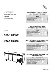
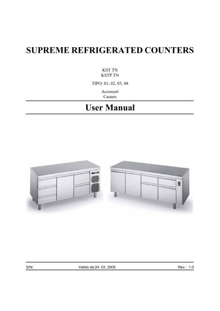
<strong>SUPREME</strong> <strong>REFRIGERATED</strong> <strong>COUNTERS</strong>KST TNKSTP TNTIPO: 01, 02, 03, 04AccessoriCasters<strong>User</strong> <strong>Manual</strong>S/N: Valido da:24. 03. 2005 Rev.: 1.0
24.3.2005 Rev. 1.0Dear Customer,Congratulations on your choice. We would like to take this opportunity to let you knowthat our whole production undergoes stringent controls and passes a thorough inspectionto check its functionality and high quality.Prior to use, we kindly advise you to read the manual thoroughly. In this way, you willlearn many proper, safe, and effective working methods that will allow you to get the mostout of your new appliance. Thanks to the directions, tips, and tricks given in this manual,you will be able to start using your appliance quickly and effortlessly. And we are surethat it won’t be long before you realize how pleasant it is to operate this product.The company reserves the right to make any technical changes.All the main technical specifications are shown on the rating plate fixed to the appliance.Shouldyou need to make a service or technical support request, please mention theserial number. In this way, it will be easier for us to deliver a better technical support toyou. In addition, we highly recommend to write your trusted technician’s contact informationin the lines below.Phone number:...................................................................................................Contact person:...............................................................................................
24.3.2005 Rev. 1.0
24.3.2005 Rev.6.1.2 Display ................................................................................................................. 146.1.3 View and change the set point ............................................................................. 156.1.4 Start a manual defrosting cycle ............................................................................ 156.1.5 Alarm signalling .................................................................................................. 156.1.6 In order to access the parameters in “Pr1” ........................................................... 157. Troubleshooting .......................................................................................... 168. Specifiche tecniche ...................................................................................... 17
General information24.3.2005 Rev. 1.01. General informationThis manual contains information on how to minimise environmental impact in compliancewith ECO-LABEL regulations (2000/40/EC).Read the instructions in this manual carefully, as they contain important information onhow to install, use and service the appliance safely, properly, and effectively.Keep this manual in a safe place for future reference by other users.This appliance should be installed following the instructions provided by the manufacturerand in compliance with all applicable local regulations. This appliance should be connectedto the power and water supply only by qualified personnel.All personnel in charge of using this appliance should be specifically trained in its operation.In the event of failure or malfunction, switch off the appliance. The periodic functionalchecks requested in this manual should be carried out according to the instructions. Havethe appliance serviced by a technically qualified person duly authorized by the manufacturerthat uses genuine spare parts. Never attempt to repair this appliance by yourself. Repairscarried out by unqualified people can cause damage.Failure to comply with the above may jeopardise the appliance’s safety.1.1 Symbols used in the manualThis symbol informs about a situation where a safety risk could be imminent. The instructionsprovided must be followed in order to prevent injury.This symbol informs about the right way to act in order to prevent bad results, damage tothe appliance, or hazardous situations.This symbol informs about tips and tricks that help the user to get the best possible performanceout of the appliance.This symbol informs about a function that needs to be taken into account when doing selfcontrol.1.2 Symbols used on the applianceThis symbol on a part warns the user that there are electrical terminals behind it. Therefore,the concerned part should only be removed by qualified personnel.1
General information24.3.2005 Rev. 1.01.3 Checking correspondence between the appliance and the manualThe rating plate of the appliance shows its serial number. If the manuals are missing, youmay order new ones from the manufacturer or your local representative. When orderingnew manuals it is essential to quote the serial number shown on the rating plate.Keep this manual as well as the wiring diagram with care, and put them at the operator’sdisposal for future reference.2
Safety24.3.2005 Rev. 1.02. Safety2.1 Using the appliance safelyRead the following directions and warnings carefully:2.2 Recommendations on how to best operate the appliance (2000/40/EC)Following the suggestions contained in this chapter will result in lower energy consumption.These appliances are designed for indoor use.Choosing a convenient installation location for the appliance is extremely important to ensureproper operation and energy savings; in fact, users who have the possibility of installingthe appliance in a non-heated or less-heated room can achieve significant energysavings.The best performance is obtained when room temperature ranges between +18°C (64°F)and +43°C (109°F) (Climate class T); +18°C (64°F) and +38°C (100°F) (Climate classST); +16°C (61°F) and +32°C (90°F) (Climate class ST); the rating plate found inside theappliance shows the climate class to which it belongs.If room temperature exceeds the values indicated by the climate class of this product,please follow the directions below: when room temperature falls below the minimum value,a proper storage temperature in the freezer compartment may not be ensured; therefore,we recommend that you use up all food contained in it as soon as possible.In order to achieve additional energy savings and ensure proper operation, we recommendthat you avoid opening the door/lid or holding it open more often or longer than necessary.It is important to let foods cool down prior to storing them in the appliance, because otherwisethey will produce steam which, in turn, favours frost build-up on the evaporator;in addition, it is important that the cool-down period is as short as possible (if possible,use blast chillers) for health and hygiene reasons.Avoid heavy frost build-up on the evaporator; if necessary, carry out additional manualdefrost cycles to melt away any frost build-up.Replace the door gasket if it is not working properly.It is useful to keep the condenser found in the appliance’s motor compartment and thespace under the refrigerator clean by removing any dust and cooking vapours.3
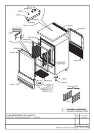
Safety24.3.2005 Rev. 1.02.2.1 Installation tipsCheck that the surface on which the appliance will rest is level and suitable to support itsweight.To ensure proper airflow and avoid any damage to the refrigeration circuit, allow a minimumside clearance of 50 mm (2 inches); do not place the appliance close to heat sources(such as ovens, radiators, etc.) or exposed to direct sunlight and provide suitable insulationfrom walls or floor if they transmit heat.If the appliance has been moved, wait for a while before switching it on again.2.3 Disposing of the appliance (environmental protection)Our appliances contain the refrigerant shown on the corresponding rating plate as perRegulation (EC) No. 2037/2000 of 29 June 2000; in addition, the appliance is composedof reusable or recyclable parts and materials. Therefore, at the end of its lifetime, the applianceshould be delivered to a specific disposal centre. The best method to ensure thatno one will remain trapped inside is to take off the door completely.The appliance must not be disposed of together with household waste and metal scrap.Absolutely avoid damaging the refrigeration circuit, particularly near the heat exchanger.Pic. 2.34
Functional description24.3.2005 Rev. 1.03. Functional description3.1 Intended useThis appliance should only be used to store food and beverages. The manufacturer shallnot be held liable for the consequences resulting from unintended uses of this appliance.Do not store food in direct contact with the structure.Both the appliance’s construction features and the condensing unit’s capacity have beendesigned to store only pre-cooled products. Never place carbonated beverages into thelow-temperature compartment as they may explode. Never place liquids or hot food intothe appliance and do not fill lidded containers to the top.In all appliances there are surfaces subject to frosting. Depending on the model, frost maybe melted away either automatically (automatic defrost) or manually. Never attempt to removefrost using a pointed object because in this way you could irreparably damage theappliance.Do not use any mechanical device or other artificial means to accelerate the defrost process.The Manufacturer declines all responsibility, and the warranty shall be null and void, ifelectrical and/or mechanical alterations are made to the product.The warranty shall also be null and void if the product is tampered with or, in general, incase of alterations not expressly authorised and not made in compliance with the instructionsgiven herein.5
Operating instructions24.3.2005 Rev. 1.04. Operating instructions4.1 Prior to use4.1.1 Preliminary checksGeneral checksTo ensure proper operation:• Check that the appliance is well levelled. If necessary, adjust the mobile part of theadjustable feet until the appliance is perfectly level.• Check that all plastic protective film has been removed from outer surfaces.• Check that the inside has been cleaned with warm water and neutral soap.• Check that the appliance is positioned as far from heat sources as possible.• Check for free, unobstructed air circulation inside motor compartment.• Check that locking keys (if available) are out of children’s reach.Checking the electrical equipment• Check that the power network voltage and frequency rating matches the valuesshown on the appliance’s rating plate (item 6 in paragraph Rating plate data).• Check that the screws fixing the wires to the electric components found in theboard are properly tightened (as vibration could have worked them loose duringhandling and transportation).• Make sure that a 16A-fuse has been fitted upstream of the power socket (outlet).• Turn OFF the general switch to which the power cord plug will be connected.• Check that the power socket (outlet) is compatible with the type of plug the appliancehas. If necessary, have the plug replaced with a suitable one by a professionallyqualified technician, who will be in charge of checking that the gauge ofsocket (outlet) wires is suitable for the appliance’s power input. Check that theplug is correctly plugged in.6
Operating instructions24.3.2005 Rev. 1.04.1.2 Start-up and checks4.2 OperationOnce you have carried out all the above steps carefully, you are ready to start up the appliance:• Turn ON the general switch to which the power supply cord plug is connected.• Turn ON the appliance’s switch.• To change the SETPOINT, refer to paragraph Thermostat operation ID a pag. 14in chapter Adjustment instructions a pag. 13.4.3 After-use careProper storage of foodstuffs is a relevant factor in the safe and sanitary production of food;in addition, it improves the efficiency of foodservice activities and positively affects energyconsumption. Follow the directions below to obtain the highest performance possibleout of your appliance.Products should be placed into the appliance in such a way as to allow unobstructed airflow.Always leave some free space between the products and prevent them from comingin contact with the walls. If needed, adjust the distance between shelves. Products shouldalways be stored on the shelves; do not place any products on the cabinet’s bottom.4.3.1 CleaningHow often you will need to clean the appliance depends largely on how often you use it.Analyze the use and schedule the required cleaning operations.To clean the appliance’s inside and outside, use a neutral or slightly alkaline detergent.We recommend that you clean the inside with a disinfectant every once in a while. Impuritiesmay be removed using a damp cloth. Removing the shelves makes cleaning the insideeasier.Prevent water from coming in contact with the electrical components. Using a pressurisedjet of water to clean the appliance is forbidden. Never use metal objects to clean the appliance,as they could damage it.7
Operating instructions24.3.2005 Rev. 1.04.3.2 Maintenance operations that may be carried out by the userUnder normal conditions of use the appliance only requires a minimum of maintenance.The user can carry out the following operations:• Cleaning the inside and outside every day or as often as needed.• Cleaning the condenser at least twice a year or more often if used in a dusty environment.Before cleaning the condenser, turn the appliance off using the mainswitch and disconnect the power cord from the power socket (outlet). Use a vacuumcleaner or a soft brush. When brushing the condenser, exercise great care so asto avoid damaging the aluminium grid.• Check that the condensate drain hose is not clogged. If needed, clean it. Possiblemalfunctions due to a clogged drain may not be attributed to the manufacturer.• Check that the fan is properly fixed to its frame.• Check for fan unbalancing, evidenced by abnormal vibration or noise, thoroughly.• Check the power cord connecting the appliance to the wall socket (outlet) for cuts,cracks, or alterations which might compromise its insulation. If the power cordneeds servicing, contact your nearest technical support centre.4.3.3 Maintenance operations to be performed by authorised technical support personnelAny maintenance operations not mentioned in the above paragraphs, should be performedby authorised technical support personnel only. The need to perform maintenance operationsdepends largely on the external conditions and how often the appliance is used.For further information, contact your local representative. Identifying the appliance correctlyis useful when ordering spare parts or requesting maintenance or repair operations.The appliance’s model and serial number are shown on the rating plate found inside theappliance.8
Operating instructions24.3.2005 Rev. 1.04.3.4 Rating plate dataPic. 4.3.4 - Rating plate1. Manufacturer2. Serial number3. Code4. Model5. Voltage6. Running absorbed current7. Refrigerant power8. Max power absorbed9. Defrost heating element power10. Other elements nominal power11. Lamp power12. Max and min. pressure13. Refrigerant, type and q.ty14. Net capacity15. Insulation expanding gas16. Manufacture year17. Climatic class9
Operating instructions24.3.2005 Rev. 1.04.3.5 Idle periodsFollow the precautions below if the appliance will be left idle for some time:• Unplug the appliance from the wall socket (outlet);• Remove all foodstuffs from the appliance;• Defrost it and clean the inside;• Leave the door partly open to favour air circulation inside the cabinet and preventunpleasant smells from forming.• Store the appliance in such a way as to avoid that anyone can remain trapped inside.10
Installation24.3.2005 Rev. 1.05. Installation5.1 General information5.2 Transport and storageEnsure that installation is performed according to the instructions given under chapterRecommendations on how to best operate the appliance (2000/40/EC) a pag. 3, Installationtips a pag. 4. We remind you that insufficient airflow will certainly result in appliancemalfunction or damage.Once the appliance has been installed, ensure that it is not resting on the power cord.In the event of damage, the power cord should only be replaced by qualified personnelwith a special cable or cable assembly available from the manufacturer.Ensure compliance with all local safety rules in force at the time of installation.Prior to plugging in the appliance, ensure that the power distribution network ratingsmatch the values shown on the appliance’s rating plate.It is absolutely necessary that the appliance be connected to an effective earth (ground)connection. To this end, the power cord plug is equipped with a grounding contact. If thepower socket (outlet) of the system is not grounded (earthed), connect the appliance to aseparate grounding (earthing) system in compliance with applicable regulations in force.Ask for a qualified technician’s advice.The manufacturer declines all responsibility in case of non-compliance with this accidentpreventionrule.You must always be able to disconnect the appliance from power supply; therefore, oncethe appliance has been installed the power socket (outlet) should be easily accessible.If possible, do not unpack the appliance until it is placed near the final installation site. Donot tip it over.If the appliance has been tipped over, wait for a while until oil settles down again.The appliance should always be stored in sheltered areas.If the appliance was stored in a cold place, thus causing the temperature of the refrigerationunit to fall below 0°C (32°F), prior to start using the appliance keep it at room temperaturefor at least one hour so that the refrigeration unit will warm up to +16°C (61°F).Turning on the appliance when temperature is excessively low may result in compressormalfunction.11
Installation24.3.2005 Rev. 1.05.3 Unpacking the appliance5.4 InstallationUnpack the appliance and check for transport damage. Remove the protective film fromthe appliance’s body.Packing materials (plastic bags, polystyrene foam, nails, etc.) should be kept out of children’sreach as they are potential sources of hazard, and they should be properly recycledin compliance with local regulations in force.Place the appliance in its final installation site.When lifting the appliance with a suitable mechanical device, ensure that the structure atthe base is undamaged.Level the appliance using its adjustable feet. Use a level, if needed. The maximum permissibledeviation from the horizontal plane is +/-0.5 degrees. All four feet should be restingon the floor. This will ensure proper door operation.5.4.1 Cleaning5.5 Electrical connectionsPrior to use, clean the inside, the shelves and the outside with a cloth and wipe dry. Toclean use a neutral or slightly alkaline detergent.5.6 First turn-onThe appliance may be switched on three hours after installation. Plug the appliance into agrounded outlet (earthed socket). To do so, you will need to have a power outlet (socket)with a built-in 16A-fuse fitted upstream of the system. Check that power supply voltagematches the value shown on the appliance’s rating plate.Check that a circuit breaker switch having a contact gap of at least 3 mm is fitted upstreamof the power socket (outlet).Turn on the appliance using the main switch. After 1 minute, the compressor will start cyclinguntil internal temperature reaches the factory-set value. Do not load the applianceuntil the set temperature value has been reached. If you need to change any factory-set parameters,please read the instructions given under chapter "Adjustment instructions".12
Adjustment instructions24.3.2005 Rev. 1.06. Adjustment instructions6.1 XW thermostat operation6.1.1 KeyboardFig. 6.1.1.1 - Thermostat XW20LS - XW60LS (KST)Fig. 6.1.1.1 - Thermostat XW20LS - XW60LS (KSTP)13
Adjustment instructions24.3.2005 Rev. 1.06.1.2 DisplaySymbols on the frontal panel• P1 -> Turns on and off the device;• P2 -> In order to view or change the set point. In programming it selects a parametero confirms a value. If pressed for three seconds when viewing MAX o mintemperature it deletes it;• P3 -> In order to see the minimum temperature reached. In programming it scrollsthe parameter codes or decreases their value;• P4 -> In order to see the max temperature reached. In programming it scrolls theparameter codes or increases their value; If pressed for 3 seconds it starts the freezingcycle;• P5 -> Holding it down for 3 seconds it starts the manual defrosting cycle;• P6 -> Turns on and off the room lights, if any.Meaning of leds• L1 -> On -> quick cooling enabled;• L2 -> On -> defrosting enabled;• L2 -> Blinking -> under dripping;• L3 -> Blinking -> under programming (it blinks along with the led L4);• L4 -> On -> compressor enabled;• L4 -> Blinking -> under programming (it blinks along with the led L3); anti-oscillationdelay;• L5 -> On -> Alarm signalling; in programming “Pr2” indicates that the parameteris also in “Pr1”;• L6 -> On -> Light enabled.The ON/OFF functionPressing the ON/OFF button, the device displays “OFF”. In this configuration all loadingsand adjustments are disabled. In order to set the device again to ON, press the buttonagain.View the minimum temperature• Press and release the P3 button;• The “Lo” message followed by the minimum temperature reached will display;• Press the P3 button or wait for 5 seconds to view the standard temperature.View the max temperature• Press and release the P4 button;• The “Hi” message followed by the max temperature reached will display;• Holding the P4 button down or waiting 5 seconds, the standard temperature willbe displayed again.14
Adjustment instructions24.3.2005 Rev. 1.0Delete the temperatures stored• In order to delete and view the temperatures stored, view the max or minimumtemperature by using the P3 and P4 buttons;• Press the P2 button until the “rST” message blinks 3 times.Block the keyboard• Hold the P3 and P4 buttons down for some seconds until the blinking “POF” signappears;• Now the keyboard is locked: only viewing set point, max and minimum temperatureis permitted;• In order to unlock the keyboard: hold the P3 and P4 buttons down for some secondsuntil the blinking “POn” sign appears.6.1.3 View and change the set point• Press and release the P2 button; the set point will be immediately displayed;• The L4 led blinks;• In order to change the value use the P3 and P4 buttons;• In order to store the new set point, press the P2 button or wait for 15 seconds toquit the programming.6.1.4 Start a manual defrosting cyclePress the P5 button for more than 2 seconds.6.1.5 Alarm signallingMessage Cause OutletsP1Thermostat probe faultyOutlet in accordance with “Con” and“COF” parametersHA Alarm for high temperature Not changedLA Alarm for low temperature Not changedEEIrregularity in the memorydA Alarm for open door Not changedEAL Alarm from digital inlet Not changedBAL Alarm for digital inlet lock Adjustment outlets disabledPAL Alarm for pressure switch from digital inlet Adjustment outlets disabled6.1.6 In order to access the parameters in “Pr1”• Press for some seconds the P2 and P3 buttons (L3 and L4 start to blink);• The device displays the first parameter in “Pr1”.15
Troubleshooting24.3.2005 Rev. 1.07. TroubleshootingIn the event of malfunction, check the list below to see if it is possible to restore the applianceto working condition without needing to call the technical support service. Forfurther information, please contact your nearest technical support centre.TROUBLE POSSIBLE CAUSE REMEDYSENSOR(S) FAILURECOMPRESSOR WILLNOT RESTARTCOMPRESSOR SEL-DOM STOPSFROSTED COMPRES-SOR SHELLNOISY APPLIANCEOVERFLOWING OFSELF-EVAPORATINGCONDENSATE TRAYSensor disconnectedSensor damagedElectrical equipment of the compressor(relay, motor protection and condenser) isfaulty.Compressor has a winding open or shorted,or there is an earth (ground) faultRoom temperature is too highRefrigerated cabinet condenser is dirtyLow refrigerant chargeDoor gaskets do not ensure proper sealFrost build-up on the evaporatorExcess refrigerant chargeFrost build-up on the evaporatorEvaporator motor fan(s) damagedLoose screwsVibrating pipesHot or high-water content foodstuffs arebeing introduced into the appliance too oftenDoors and/or drawers are opened too oftenConnect sensor to the thermostat againCall an authorised technical support centre tohave it replacedCall an authorised technical support centre tohave the concerned component replacedCall an authorised technical support centre tohave the compressor replacedEnsure proper ventilation to the roomCheck it on a regular basis and clean it thoroughlyCall an authorised technical support centre tofind and repair any leaks and to recharge thecompressor with refrigerant.Call an authorised technical support centre toperform the necessary replacementDo not place hot or high water content foodstuffsinto the appliance and, if needed, perform a manualdefrost cycle.Call an authorised technical support centreDo not place hot or high water content foodstuffsinto the appliance and, if needed, perform a manualdefrost cycle.Call an authorised technical support centre toperform the necessary replacementCheck that all screws are tightened and tightenthem if needed.Check that they are well fixed and, if needed,space adjoining pipes out so that they do not collide.Do not introduce hot or high water content foodstuffsinto the appliance.Pay attention to the conditions of use of your appliance.16
Specifiche tecniche24.3.2005 Rev. 1.08. Specifiche tecnicheMotorised refrigeration circuit diagram, KSTRefrigeration circuit diagram of remote-refrigerated appliances,KSTP ..................................Schema elettrico KST TN; 01, 02........Schema elettrico KST TN; 03, 04........Schema elettrico KSTP TN; 01, 02 .....Schema elettrico KSTP TN; 03, 04 .....Installation drawing KST TN..............Installation drawing KSTP TN ...........17
Specifiche tecniche24.3.2005 Rev. 1.0Motorised refrigeration circuit diagram, KSTDescription1 Compressor2 Condenser3 Filter drier dirty4 Capillary tube5 Evaporator18
Specifiche tecniche24.3.2005 Rev. 1.0Refrigeration circuit diagram of remote-refrigerated appliances, KSTPDescription1 Compressor2 Condenser3 Filter drier dirty4 Valve5 Evaporator19
Schema elettrico KST TN; 01, 02
Specifiche tecniche24.3.2005 Rev. 1.0M1M2M3R1R2R3ST1101113DescriptionMOTOR COMPRESSORCONDENSER MOTOR FANCABINET MOTOR FANCONDENSATE TRAY HEATERDOOR FRAME HEATERDRAIN HEATERELECTRONIC CABINET THERMOSTATTO BE CONNECTED BY THE INSTALLERONLY ON REQUESTFOR BT MODELS ONLY21
Schema elettrico KST TN; 03, 04
Specifiche tecniche24.3.2005 Rev. 1.0M1M2M3R2R3ST113DescriptionMOTOR COMPRESSORCONDENSER MOTOR FANCABINET MOTOR FANDOOR FRAME HEATERDRAIN HEATERELECTRONIC CABINET THERMOSTATFOR BT MODELS ONLY23
Schema elettrico KSTP TN; 01, 02
Specifiche tecniche24.3.2005 Rev. 1.0M1M2M3R1R2R3ST1101113DescriptionMOTOR COMPRESSORCONDENSER MOTOR FANCABINET MOTOR FANCONDENSATE TRAY HEATERDOOR FRAME HEATERDRAIN HEATERELECTRONIC CABINET THERMOSTATTO BE CONNECTED BY THE INSTALLERONLY ON REQUESTFOR BT MODELS ONLY25
Schema elettrico KSTP TN; 03, 04
Specifiche tecniche24.3.2005 Rev. 1.0M1M2M3R1R2R3ST1101113DescriptionMOTOR COMPRESSORCONDENSER MOTOR FANCABINET MOTOR FANCONDENSATE TRAY HEATERDOOR FRAME HEATERDRAIN HEATERELECTRONIC CABINET THERMOSTATTO BE CONNECTED BY THE INSTALLERONLY ON REQUESTFOR BT MODELS ONLY27
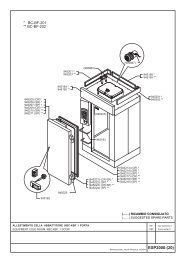
Specifiche tecniche24.3.2005 Rev. 1.0Installation drawing KST TN12581722KST 02KST 0370050 50 40 8083 1088838315528350894218669050KST 01KST 04800557626083 72483831077 93983 123 501 664641756570KST 01EVAPORATOREVAPORATORKST 04EVAPORATOR8281292570KST 02EVAPORATOREVAPORATORKST 03EVAPORATOR28
Specifiche tecniche24.3.2005 Rev. 1.0Installation drawing KSTP TN29
Specifiche tecniche24.3.2005 Rev. 1.0Item Model Type SpecificationNominal gross volume 01 145 lNominal gross volume 02 261 lNominal gross volume 03 406 lNominal gross volume 04 551 lTotal weight KSTTN 01 110 KgTotal weight KSTTN 02 155 KgTotal weight KSTTN 03 200 KgTotal weight KSTTN 04 260 KgTotal weight KSTPTN 01 80 KgTotal weight KSTPTN 02 125 KgTotal weight KSTPTN 03 170 KgTotal weight KSTPTN 04 230 KgPackage dimensions WxDxH KSTTN 01 1000x800x1000 mmPackage dimensions WxDxH KSTTN 02 1360x800x1000 mmPackage dimensions WxDxH KSTTN 03 1830x800x1000 mmPackage dimensions WxDxH KSTTN 04 2290x800x1000 mmPackage dimensions WxDxH KSTPTN 01 830x800x1000 mmPackage dimensions WxDxH KSTPTN 02 1190x800x1000 mmPackage dimensions WxDxH KSTPTN 03 1660x800x1000 mmPackage dimensions WxDxH KSTPTN 04 2120x800x1000 mmVolume with package KSTTN 01 0,8 m3Volume with package KSTTN 02 1,1 m3Volume with package KSTTN 03 1,5 m3Volume with package KSTTN 04 1,9 m3Volume with package KSTPTN 01 0,7 m3Volume with package KSTPTN 02 1,0 m3Volume with package KSTPTN 03 1,4 m3Volume with package KSTPTN 04 1,7 m3Voltage1/N/PE AC 230 V 50 HzPower of compressor KSTTN 01 226 W (CECOMAF -10+55)Power of compressor KSTTN 02 254 W (CECOMAF -10+55)Power of compressor KSTTN 03 324 W (CECOMAF -10+55)Power of compressor KSTTN 04 484 W (CECOMAF -10+55)Power of compressor KSTPTN 01 272 W (CECOMAF -10+55)Power of compressor KSTPTN 02 305 W (CECOMAF -10+55)Power of compressor KSTPTN 03 389 W (CECOMAF -10+55)Power of compressor KSTPTN 04 581 W (CECOMAF -10+55)Working temperature KSTTN -2 / +8 °CWorking temperature KSTPTN -2 / +8 °CRefrigerant feed KSTTN CapillaryRefrigerant feed KSTPTN With valveRefrigerant systemVentilatedType of defrostElectricalDefrosts per day / Defrost duration time (min) 4 / 30Current absorbed during operation KSTTN 01 1,6 A30
Specifiche tecniche24.3.2005 Rev. 1.0Item Model Type SpecificationCurrent absorbed during operation KSTTN 02 1,7 ACurrent absorbed during operation KSTTN 03 2,7 ACurrent absorbed during operation KSTTN 04 3,1 ACurrent absorbed during operation KSTPTN 01 -Current absorbed during operation KSTPTN 02 -Current absorbed during operation KSTPTN 03 -Current absorbed during operation KSTPTN 04 -Current KSTTN 01 1,6 ACurrent KSTTN 02 1,7 ACurrent KSTTN 03 2,7 ACurrent KSTTN 04 3,1 ACurrent KSTPTN 01 -Current KSTPTN 02 -Current KSTPTN 03 -Current KSTPTN 04 -Power absorbed during operation KSTTN 01 300 WPower absorbed during operation KSTTN 02 310 WPower absorbed during operation KSTTN 03 410 WPower absorbed during operation KSTTN 04 530 WPower absorbed during operation KSTPTN 01 -Power absorbed during operation KSTPTN 02 -Power absorbed during operation KSTPTN 03 -Power absorbed during operation KSTPTN 04 -Power absorbed max KSTTN 01 300 WPower absorbed max KSTTN 02 310 WPower absorbed max KSTTN 03 410 WPower absorbed max KSTTN 04 530 WPower absorbed max KSTPTN 01 -Power absorbed max KSTPTN 02 -Power absorbed max KSTPTN 03 -Power absorbed max KSTPTN 04 -Fuse16 ARefrigerant type KSTTN R134aRefrigerant type KSTPTN R134aQuantity of refrigerant KSTTN 01 200 grQuantity of refrigerant KSTTN 02 200 grQuantity of refrigerant KSTTN 03 260 grQuantity of refrigerant KSTTN 04 270 grQuantity of refrigerant KSTPTN 01 -Quantity of refrigerant KSTPTN 02 -Quantity of refrigerant KSTPTN 03 -Quantity of refrigerant KSTPTN 04 -Heat emitted KSTTN 01 300 WHeat emitted KSTTN 02 360 WHeat emitted KSTTN 03 460 WHeat emitted KSTTN 04 570 W31
Specifiche tecniche24.3.2005 Rev. 1.0KSTTN=KST TN, KSTPTN=KSTP TN01=01, 02=02, 03=03, 04=04W=CastersP=1/N/PE~220-240V 50HzItem Model Type SpecificationHeat emitted KSTPTN 01 -Heat emitted KSTPTN 02 -Heat emitted KSTPTN 03 -Heat emitted KSTPTN 04 -Air capacity KSTTN 01 220 m3/hAir capacity KSTTN 02 245 m3/hAir capacity KSTTN 03 245 m3/hAir capacity KSTTN 04 245 m3/hAir capacity KSTPTN 01 -Air capacity KSTPTN 02 -Air capacity KSTPTN 03 -Air capacity KSTPTN 04 -32
Specifiche tecniche24.3.2005 Rev. 1.033