Verification of Superposition theorem and Thevenin's theorem
Verification of Superposition theorem and Thevenin's theorem
Verification of Superposition theorem and Thevenin's theorem
You also want an ePaper? Increase the reach of your titles
YUMPU automatically turns print PDFs into web optimized ePapers that Google loves.
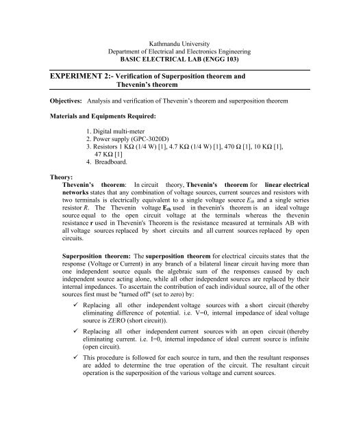
Procedure:i) Thevenin Theorem- Connect the circuit as shown in figure 1 on the breadboard- Measure the voltage across AB (i.e. p.d. across load resistor).- Remove load resistor (for first case it is 4.7KΩ).- Measure the open circuit voltage across AB with the help <strong>of</strong> multimeter ( Placing positiveterminal <strong>of</strong> multimeter at A <strong>and</strong> negative at B)- Measure the Thevenin’s resistance with the help <strong>of</strong> multimeter (with short circuitingvoltage sources <strong>and</strong> open circuiting current sources (if any) (Alternatively you canmeasure the short circuit current through load).- Connect the circuit as shown in figure 2; replacing ETH <strong>and</strong> RTH are open circuit voltage<strong>and</strong> Thevenin resistance respectively, as measured in third step.- Connect the load <strong>and</strong> measure the voltage across load with the help <strong>of</strong> voltmeter.- REPEAT above steps for different load resistor.Circuit Diagram:Figure 1 Figure 2NOTE: You now need only one voltage source, but you will probably need to use acombination <strong>of</strong> resistors in series to obtain Req. Similarly the resistor value may notbe exact as specifiedii) <strong>Superposition</strong> <strong>theorem</strong>- Connect the circuit as shown in figure 1 on the breadboard.- Set the value <strong>of</strong> voltage supply 1 to 0 V <strong>and</strong> supply 2 to 7 V <strong>and</strong> measure the potentialdifference across A <strong>and</strong> B. Also measure the current through load <strong>of</strong> 4.7KΩ.- Set the value <strong>of</strong> voltage supply 2 to 0 V <strong>and</strong> supply 1 to 10 V <strong>and</strong> measure the potentialdifference across A <strong>and</strong> B. Also measure the current through load <strong>of</strong> 4.7KΩ.- Now set the value <strong>of</strong> voltage supply 1 to 7 V <strong>and</strong> supply 2 to 10V <strong>and</strong> measure thepotential difference across A <strong>and</strong> B <strong>and</strong> current through load <strong>of</strong> 4.7KΩ.- REPEAT above steps for different load resistor.
Observations:1. Measurement <strong>and</strong> Calculation <strong>of</strong> Thevenin circuit parametersS.N. V OC R TH V OC (Fromcalculation)R TH (Fromcalculation)12. <strong>Verification</strong> <strong>of</strong> Thevenin’s <strong>theorem</strong>S.N R LOAD V AB from circuit<strong>of</strong> figure 1V AB from Theveninequivalent circuitI L from circuit<strong>of</strong> figure 1I L from Theveninequivalent circuit1 4.7 KΩ2 10 KΩ3 47 KΩ‣ Do these measurements taken from Thevenin equivalent circuit agree with themeasurements from the original circuit?3. <strong>Verification</strong> <strong>of</strong> <strong>Superposition</strong> <strong>theorem</strong>S.NRLOADV 1 =VAB(V Source1 =0V)V 2 =VAB(V Source2 =0V)V AB =V 1 +V 2I 1 when(V Source1 =0V)I 2 when(V Source2 =0V)I=I 1 +I 21 4.7KΩ2 10KΩ3 47KΩ‣ Do these measurements taken from <strong>Superposition</strong> <strong>theorem</strong> <strong>and</strong> thevenin <strong>theorem</strong> agreewith the measurements from the original circuit? Original value is to be tabulated intable 2
Conclusions <strong>and</strong> Inference:………………………………………………………………………………………………………………………………………………………………………………………………………………………………………………………………………………………………………………………………………………………………………………………………………………………………………………………………………………………………………………………………………………………………………………………………………………………………………………………………………………………………………………………………………………………………………………………………………………………………………………………………………………………………………………………………………………………………………………………………………………………………………………………………………………………………………………………………………………………………………………………………………………………………………………………………………………………………………………………………………………………………………………………………………………………………………………………………………………………………………………………………………………………………………………………………………………………………………………………………………………………………………………………………………………………………………………………………………………………………………………………………………………………………………………………………………………………………………………………………………………………………………………………………………………………………………………………………………………………………………………………………………………………………………………………………………………………………………………………………………………………………………………………………………………………………………………………………………………………………………………………………………………………………………………………………………………………………………………………………………………………………………………………………………………………………………………………………………………………………………………………………………………………………………………………………………………………………………………………………………………………………………………………………………………………………………………………………………………………………………………………………………………………………………………………………………………………………Exercises:i) Discuss the relationship <strong>of</strong> terminal voltage with increase in load resistance.ii) Calculate the value <strong>of</strong> thevenin equivalent circuit in paper <strong>and</strong> compare with theexperimental results.iii) Calculate <strong>and</strong> compare the total power supplied by sources in the original circuit<strong>and</strong> thevenin circuit from experimental data.Instructor’s Signature Performance Date Submission Date


