DF DIFFERENTIAL
DF DIFFERENTIAL
DF DIFFERENTIAL

You also want an ePaper? Increase the reach of your titles
YUMPU automatically turns print PDFs into web optimized ePapers that Google loves.
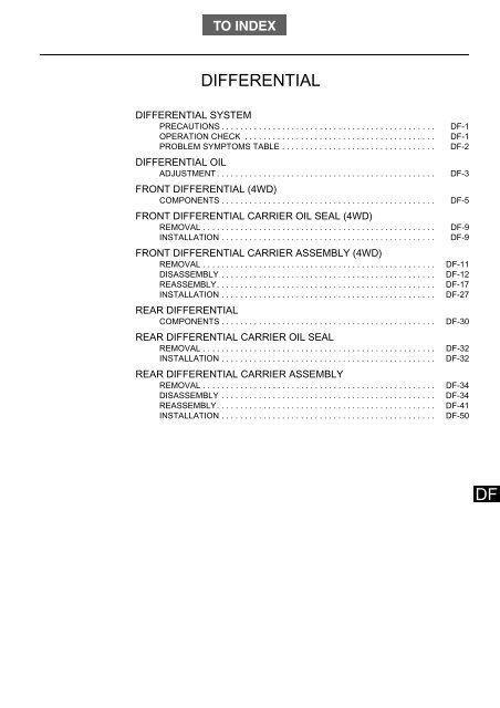
TO INDEXDRIVE LINE / AXLE<strong>DIFFERENTIAL</strong><strong>DIFFERENTIAL</strong> SYSTEMPRECAUTIONS . . . . . . . . . . . . . . . . . . . . . . . . . . . . . . . . . . . . . . . . . . . . . .OPERATION CHECK . . . . . . . . . . . . . . . . . . . . . . . . . . . . . . . . . . . . . . . . .PROBLEM SYMPTOMS TABLE . . . . . . . . . . . . . . . . . . . . . . . . . . . . . . . . .<strong>DIFFERENTIAL</strong> OILADJUSTMENT . . . . . . . . . . . . . . . . . . . . . . . . . . . . . . . . . . . . . . . . . . . . . . .FRONT <strong>DIFFERENTIAL</strong> (4WD)COMPONENTS . . . . . . . . . . . . . . . . . . . . . . . . . . . . . . . . . . . . . . . . . . . . . .FRONT <strong>DIFFERENTIAL</strong> CARRIER OIL SEAL (4WD)REMOVAL . . . . . . . . . . . . . . . . . . . . . . . . . . . . . . . . . . . . . . . . . . . . . . . . . .INSTALLATION . . . . . . . . . . . . . . . . . . . . . . . . . . . . . . . . . . . . . . . . . . . . . .FRONT <strong>DIFFERENTIAL</strong> CARRIER ASSEMBLY (4WD)REMOVAL . . . . . . . . . . . . . . . . . . . . . . . . . . . . . . . . . . . . . . . . . . . . . . . . . .DISASSEMBLY . . . . . . . . . . . . . . . . . . . . . . . . . . . . . . . . . . . . . . . . . . . . . .REASSEMBLY. . . . . . . . . . . . . . . . . . . . . . . . . . . . . . . . . . . . . . . . . . . . . . .INSTALLATION . . . . . . . . . . . . . . . . . . . . . . . . . . . . . . . . . . . . . . . . . . . . . .REAR <strong>DIFFERENTIAL</strong>COMPONENTS . . . . . . . . . . . . . . . . . . . . . . . . . . . . . . . . . . . . . . . . . . . . . .REAR <strong>DIFFERENTIAL</strong> CARRIER OIL SEALREMOVAL . . . . . . . . . . . . . . . . . . . . . . . . . . . . . . . . . . . . . . . . . . . . . . . . . .INSTALLATION . . . . . . . . . . . . . . . . . . . . . . . . . . . . . . . . . . . . . . . . . . . . . .REAR <strong>DIFFERENTIAL</strong> CARRIER ASSEMBLYREMOVAL . . . . . . . . . . . . . . . . . . . . . . . . . . . . . . . . . . . . . . . . . . . . . . . . . .DISASSEMBLY . . . . . . . . . . . . . . . . . . . . . . . . . . . . . . . . . . . . . . . . . . . . . .REASSEMBLY. . . . . . . . . . . . . . . . . . . . . . . . . . . . . . . . . . . . . . . . . . . . . . .INSTALLATION . . . . . . . . . . . . . . . . . . . . . . . . . . . . . . . . . . . . . . . . . . . . . .<strong>DF</strong>-1<strong>DF</strong>-1<strong>DF</strong>-2<strong>DF</strong>-3<strong>DF</strong>-5<strong>DF</strong>-9<strong>DF</strong>-9<strong>DF</strong>-11<strong>DF</strong>-12<strong>DF</strong>-17<strong>DF</strong>-27<strong>DF</strong>-30<strong>DF</strong>-32<strong>DF</strong>-32<strong>DF</strong>-34<strong>DF</strong>-34<strong>DF</strong>-41<strong>DF</strong>-50<strong>DF</strong>
<strong>DF</strong>–1<strong>DIFFERENTIAL</strong> SYSTEMDRIVE LINE / AXLE<strong>DIFFERENTIAL</strong> <strong>DIFFERENTIAL</strong> SYSTEMPRECAUTIONS<strong>DF</strong>1. Before disassembly, clean the outside of the differentialassembly and remove any sand or mud to prevent it fromentering the inside of the assembly during disassembly orinstallation.2. When disassembling a connecting part made of light alloy suchas a differential carrier cover, lightly tap it in with a plastichammer. Do not attempt to pry it off with a screw driver.3. Always organize and arrange the disassembled parts properly toprotect them from dust or other foreign matter.4. Fully wash and dry each part before installing it, and applydifferential gear oil.Do not use alkaline cleaner for aluminum orrubber parts or ring gear set bolts.In addition, do not cleanrubber parts such as O-rings or oil seals with cleaning oils (suchas solvent).5. Sufficiently coat the sliding and rotating surfaces withdifferential gear oil before installation.6. When securing parts in a vise, do not place the parts directly inthe vice. Be sure to place aluminum plates between the partsand the vice.7. Be extremely careful not to damage the contact surfaces of thecase. Such damage may cause oil leaks.8. Before applying sealant, remove the old adhesive or old sealantfrom the seal, and clean the area with a solvent.9. Do not fill oil immediately after installing sealed parts. Wait atleast an hour.10. As it may cause oil leaks, do not scratch or damage the contactsurfaces of the oil seal, O-ring, or gasket.11. When tapping the oil seal into the end of the differential carrier,inspect the installation depth at 3 or more locations on the oilseal circumference. To prevent oil leakage, make sure that thedifference between the maximum and minimum measurementvalues is within the standard value range.12. When press-fitting an oil seal, be extremely careful not todamage the oil seal lip or its outer circumference.13. When replacing a bearing, replace the outer and inner races as aset.OPERATION CHECK1. INSPECT <strong>DIFFERENTIAL</strong> OIL(a) CHECK OIL LEVEL (See page <strong>DF</strong>-3 for the procedure.)(b) CHECK FOR OIL LEAKS(1) Visually inspect whether oil is leaking from the oil seal,differential carrier, plug, case fitting surface, or any otherparts.
<strong>DIFFERENTIAL</strong> <strong>DIFFERENTIAL</strong> SYSTEMPROBLEM SYMPTOMS TABLE<strong>DF</strong>–2Symptom Suspected Area See PageOil level (low)<strong>DF</strong>-3Ring gear or pinion gear (worn or chipped)<strong>DF</strong>-12Noise from the front differentialMisalignment of the backlash<strong>DF</strong>-13Misalignment of the preload<strong>DF</strong>-14Misalignment of the tooth contact pattern<strong>DF</strong>-22Worn bearing<strong>DF</strong>-12Oil level (low)<strong>DF</strong>-3Ring gear or pinion gear (worn or chipped)<strong>DF</strong>-34Noises from the rear differentialMisalignment of the backlash<strong>DF</strong>-35Misalignment of the preload<strong>DF</strong>-46Misalignment of the tooth contact pattern<strong>DF</strong>-46Worn bearing<strong>DF</strong>-34Oil leakage from the front differentialOil level (high)<strong>DF</strong>-3Carrier oil seal (worn or damaged)<strong>DF</strong>-9Oil leakage from the rear differentialOil level (high)<strong>DF</strong>-3Carrier oil seal (worn or damaged)<strong>DF</strong>-32<strong>DF</strong>
<strong>DF</strong>–3<strong>DIFFERENTIAL</strong> OILDRIVE LINE / AXLE<strong>DIFFERENTIAL</strong> <strong>DIFFERENTIAL</strong> OILADJUSTMENT1. DRAIN <strong>DIFFERENTIAL</strong> OIL(a) Put an oil tray under the drain plug.(b) Remove the drain plug, then remove the filler plug.(c) Check that the oil has drained completely.(d) Tighten the drain plug using the specified torque.Torque: 61 N*m (625 kgf*cm)2. ADD <strong>DIFFERENTIAL</strong> OIL(a) Make sure that the vehicle is level.(b) Remove the differential filler plug and gasket.(c) Insert the gear oil injection nozzle, and slowly fill with hypoidgear oil (differential oil).NOTICE:If the oil is filled too quickly, it may flow back. This maycause you think mistakenly that the specified amount hasbeen added.(d) Leave to stand for 5 minutes after the oil overflow from the fillerplug stops.<strong>DF</strong>0-5 mmOil LevelFiller PlugWireC1326853. INSPECT AND ADJUST <strong>DIFFERENTIAL</strong> OIL(a) Using your fingers or a wire, inspect the oil level.Standard:Within 0 to 5 mm from the bottom edge of the filler plugholeNOTICE:• As it may take some time for the oil to fill into thedifferential, be sure to wait before checking the oil level.• If the oil level is too high or too low, it may causetrouble.• Stop the vehicle on a level road.(b) If the oil level is low, check for oil leaks and add oil.(c) After oil is added, re-check that the oil has been filled up to thespecified level.(d) Install the differential filler plug and a new gasket.Standard:T = 49 N*m (500 kgf*cm) (front differential)T = 61 N*m (625 kgf*cm) (rear differential)4. ADD <strong>DIFFERENTIAL</strong> OIL(a) Remove the differential filler plug and gasket.(b) Rear differential (with LSD)(1) Add differential hypoid gear oil (LSD)Standard:Within 0 - 5 mm from the bottom edge of the filler plug opening.Full capacity:Approx. 1.81 liter(c) Front and rear deferential(1) Add hypoid gear oil (differential oil)Standard:Within 0 - 5 mm from the bottom edge of the filler plug opening.
<strong>DIFFERENTIAL</strong> <strong>DIFFERENTIAL</strong> OIL<strong>DF</strong>–4(d)(e)Full capacity:Approx. 0.45 literApprox. 1.81 liter (rear differential)Check the oil level.Install the differential filler plug and a new gasket.Standard:T = 49 N*m (500 kgf*cm) (front differential)T = 61 N*m (625 kgf*cm) (rear differential)NOTICE:After adding oil, re-check the oil level after driving.<strong>DF</strong>
<strong>DF</strong>–5FRONT <strong>DIFFERENTIAL</strong>(4WD)DRIVE <strong>DIFFERENTIAL</strong> LINE / AXLECOMPONENTS<strong>DIFFERENTIAL</strong> FRONT <strong>DIFFERENTIAL</strong>(4WD)×7T=5.4{55}ENGINE UNDER COVER RR RH<strong>DF</strong>×4T=5.4{55}ENGINE UNDER COVER RR LHENGINE UNDER COVER×11TIGHTENING TORQUE [N*m{kgf*cm}]C139174J02
<strong>DIFFERENTIAL</strong> FRONT <strong>DIFFERENTIAL</strong>(4WD)<strong>DF</strong>–6FRONT DRIVE SHAFT ASSEMBLY LHT=18.2{186}SPEED SENSOR FR LH(With ABS)T=8.4{86}TIE ROD END LHT=46.6{475}CLIPFRONT STABILIZERLINK RO<strong>DF</strong>RONT AXLEHUB NUT LHT=76.5{780}T=205.8{2099}FRONT SUSPENSIONLOWER ARM NO. 1 LHT=37.3{380}T=58.1{592}CLIP<strong>DF</strong>TIGHTENING TORQUE [N*m{kgf*cm}]NON-REUSEABLE PARTC140799J01
<strong>DF</strong>–7<strong>DIFFERENTIAL</strong> FRONT <strong>DIFFERENTIAL</strong>(4WD)T=76{775}×3T=41.7{425}FRONT <strong>DIFFERENTIAL</strong> MOUNT CUSHION NO. 1FRONT <strong>DIFFERENTIAL</strong> BRACKET RRT=76{775}×3FRONT <strong>DIFFERENTIAL</strong>CARRIER ASSEMBLY×4T=76{775}T=76{775}×4<strong>DF</strong>T=41.7{425}FRONT <strong>DIFFERENTIAL</strong> CARRIERSUPPORT BRACKET...... TIGHTENING TORQUE [N*m{kgf*cm}]C136382J01
<strong>DIFFERENTIAL</strong> FRONT <strong>DIFFERENTIAL</strong>(4WD)<strong>DF</strong>–8FRONT <strong>DIFFERENTIAL</strong>PINIONFRONT <strong>DIFFERENTIAL</strong>PINION SHAFT<strong>DIFFERENTIAL</strong> SIDEGEAR THRUST WASHER<strong>DIFFERENTIAL</strong>SIDE GEAR<strong>DIFFERENTIAL</strong>SIDE OIL SEALFRONT <strong>DIFFERENTIAL</strong>PINION<strong>DIFFERENTIAL</strong>SIDE GEARFILLER PLUGGASKETFRONT <strong>DIFFERENTIAL</strong> DRIVEPINION BEARING SPACER<strong>DIFFERENTIAL</strong> SIDEGEAR THRUST WASHER<strong>DIFFERENTIAL</strong>CARRIERFRONT DRIVE PINIONCOMPANION FLANGE FRFRONT DRIVEPINION NUTFRONT DRIVE PINIONTAPERED ROLLER BEARING RRT=118{1203}BREATHER PLUGT=11.3{115}FRONT <strong>DIFFERENTIAL</strong>CASE BEARINGSHIMT=83.4{849}×8T=49{500}T=30{306}<strong>DIFFERENTIAL</strong>CASE NO.1DRAIN PLUGGASKETSHIMSHIMFRONT <strong>DIFFERENTIAL</strong>CARRIER OIL SEAL×8T=20.6{210}<strong>DIFFERENTIAL</strong> CARRIERCOVER<strong>DIFFERENTIAL</strong>RING GEARSHIMFRONT <strong>DIFFERENTIAL</strong>CASE BEARING<strong>DIFFERENTIAL</strong>DRIVE PINIONFRONT DRIVE PINION TAPEREDROLLER BEARING FR<strong>DIFFERENTIAL</strong> SIDE OIL SEAL<strong>DF</strong>TIGHTENING TORQUE [N*m{kgf*cm}]NON-REUSEABLE PARTC140217J01
<strong>DF</strong>–9<strong>DIFFERENTIAL</strong> FRONT <strong>DIFFERENTIAL</strong> CARRIER OIL SEAL (4WD)FRONT <strong>DIFFERENTIAL</strong> CARRIER OIL SEAL (4WD)DRIVE <strong>DIFFERENTIAL</strong> LINE / AXLEREMOVAL1. REMOVE ENGINE UNDER COVER2. REMOVE ENGINE UNDER COVER RR RH (WITH ENGINE UNDERCOVER RR RH)3. REMOVE ENGINE UNDER COVER RR LH (WITH ENGINE UNDERCOVER RR LH)4. DRAIN TRANSFER OIL(See page TF-7)5. REMOVE FRONT SUSPENSION CROSS MEMBER LWR(See pagePR-3)6. REMOVE FRONT PROPELLER SHAFT ASSEMBLY (See page PR-3)7. DRAIN <strong>DIFFERENTIAL</strong> OIL(See page <strong>DF</strong>-11)8. REMOVE FRONT DRIVE PINION COMPANION FLANGE FR(a) Using a chisel and a hammer, unstake the companion flangenut.NOTICE:• When removing the nut, completely unstake it.• Do not damage the threads of the drive pinion.(b) Using the SST, secure the companion flange FR.(c) Using a deep socket wrench (0.87in), remove the companionflange nut and plate washer.(d) Using the SST, remove the companion flange.NOTICE:Apply grease to the threads and tip of the SST center boltbefore use.9. REMOVE FRONT <strong>DIFFERENTIAL</strong> CARRIER OIL SEALSST 09308-10010<strong>DF</strong>SST(a)Using the SST, remove the oil seal.NOTICE:Apply grease to the threads and tip of the SST center boltbefore use.INSTALLATION1. INSTALL FRONT <strong>DIFFERENTIAL</strong> CARRIER OIL SEALSST 09636-20010C137413
<strong>DIFFERENTIAL</strong> FRONT <strong>DIFFERENTIAL</strong> CARRIER OIL SEAL (4WD)<strong>DF</strong>–10SST(a)(b)Using the SST and a hammer, drive in a new carrier oil seal.Make sure that the seal is installed according to the standardbelow.Standard:0.5 ± 0.5 mm (from the carrier end face)Apply MP grease to the lip of the carrier oil seal.C1398182. INSTALL FRONT DRIVE PINION COMPANION FLANGE FR(a) Install the companion flange FR.(b) Using the SST, secure the companion flange FR.(c) Using the SST, hold the companion flange and install the platewasher and lock nut.(d) Using a chisel and a hammer, stake the companion flange nut.3. INSTALL FRONT PROPELLER SHAFT ASSEMBLY(See page PR-4)4. INSTALL FRONT SUSPENSION CROSS MEMBER LWR(See pagePR-4)5. ADD TRANSFER OIL(See page TF-6)6. ADD <strong>DIFFERENTIAL</strong> OIL(See page <strong>DF</strong>-3)7. INSPECT AND ADJUST TRANSFER OIL(See page TF-6)8. INSPECT AND ADJUST <strong>DIFFERENTIAL</strong> OIL(See page <strong>DF</strong>-3)9. INSTALL ENGINE UNDER COVER RR RH (WITH ENGINE UNDERCOVER RR RH)10. INSTALL ENGINE UNDER COVER RR LH (WITH ENGINE UNDERCOVER RR LH)11. INSTALL ENGINE UNDER COVER<strong>DF</strong>
<strong>DF</strong>–11<strong>DIFFERENTIAL</strong> FRONT <strong>DIFFERENTIAL</strong> CARRIER ASSEMBLY (4WD)FRONT <strong>DIFFERENTIAL</strong> CARRIER ASSEMBLY (4WD)DRIVE <strong>DIFFERENTIAL</strong> LINE / AXLEREMOVAL1. DRAIN <strong>DIFFERENTIAL</strong> OIL(a) Remove the differential filler plug and gasket.(b) Remove the drain plug and gasket and drain the oil.(c) Install the drain plug and a new gasket.Torque: 30 N*m (306 kgf*cm)2. REMOVE FRONT TIRE3. REMOVE ENGINE UNDER COVER4. REMOVE ENGINE UNDER COVER RR RH5. REMOVE ENGINE UNDER COVER RR LH6. REMOVE FRONT AXLE HUB NUT LH(See page DS-5)7. REMOVE FRONT AXLE HUB NUT RH(a) Perform the same procedure for the RH side as for the LH side.8. REMOVE TIE ROD END LH (See page DS-5)9. REMOVE TIE ROD END RHHINT:Perform the same procedure for the RH side as for the LH side.10. REMOVE FRONT STABILIZER LINK ROD(See page SP-14)11. DISCONNECT FRONT SUSPENSION LOWER ARM NO. 1 LH(Seepage DS-5)12. DISCONNECT FRONT SUSPENSION LOWER ARM NO. 1 RHHINT:Perform the same procedure for the RH side as for the LH side.13. DISCONNECT FRONT AXLE HUB LH(See page DS-5)14. DISCONNECT FRONT AXLE RHHINT:Perform the same procedure for the RH side as for the LH side.15. REMOVE FRONT DRIVE SHAFT ASSEMBLY LH(See page DS-6)<strong>DF</strong>16. REMOVE FRONT DRIVE SHAFT ASSEMBLY RHHINT:Perform the same procedure for the RH side as for the LH side.17. REMOVE FRONT SUSPENSION CROSS MEMBER LWR(See pagePR-3)18. REMOVE FRONT PROPELLER SHAFT ASSEMBLY (See page PR-3)19. SUPPORT FRONT <strong>DIFFERENTIAL</strong> CARRIER ASSEMBLY(a) Support the front differential carrier assembly with atransmission jack.NOTICE:As the front differential carrier assembly is heavy, be surethat it is securely supported with the transmission jack.
<strong>DIFFERENTIAL</strong> FRONT <strong>DIFFERENTIAL</strong> CARRIER ASSEMBLY (4WD)<strong>DF</strong>–1220. REMOVE FRONT <strong>DIFFERENTIAL</strong> CARRIER ASSEMBLY(a) Remove the bolt and disconnect front differential mount cushionNo. 1 from the front suspension cross member.C137248J01(b)Remove the 2 bolts, then remove the front differential carrierassembly (with bracket).NOTICE:• Do not lose the front differential carrier assembly.• When removing the front differential carrier assembly,there is a possibility of leakage of residual oil.C13601121. REMOVE FRONT <strong>DIFFERENTIAL</strong> CARRIER SUPPORT BRACKET(a) Remove the 4 bolts, then remove the front differential carriersupport bracket from the front differential carrier.22. REMOVE FRONT <strong>DIFFERENTIAL</strong> MOUNT CUSHION NO. 1(a) Remove the 3 bolts, then remove front differential mountcushion No. 1 from front differential mount No. 1.23. REMOVE FRONT <strong>DIFFERENTIAL</strong> BRACKET RR(a) Remove the 7 bolts, then remove the front differential bracketRR from the front differential carrier.DISASSEMBLY1. REMOVE FRONT <strong>DIFFERENTIAL</strong> CARRIER COVER BREATHERPLUG(a) Remove the breather plug from the carrier plug.SST2. REMOVE <strong>DIFFERENTIAL</strong> SIDE OIL SEAL(a) Using the SST, remove the right and left side gear shaft oil seal.SST 09308-00010<strong>DF</strong>C1369163. REMOVE FRONT <strong>DIFFERENTIAL</strong> CARRIER COVER(a) Remove the 8 bolts.(b) Using a brass bar and a hammer, lightly tap on the differentialcarrier cover to remove it.NOTICE:• Place the brass bar against the ribs of the carrier cover.• Do not damage the contact surfaces of the differentialcarrier.C1372494. SECURE <strong>DIFFERENTIAL</strong> CARRIER ASSEMBLYSST 09219-87701, 09219-87202
<strong>DF</strong>–13<strong>DIFFERENTIAL</strong> FRONT <strong>DIFFERENTIAL</strong> CARRIER ASSEMBLY (4WD)(a)Install the SST to the front differential carrier assembly.SSTC139756SSTSST(b)Secure the front differential carrier assembly to the SST.C139757C1372705. INSPECT RUNOUT OF <strong>DIFFERENTIAL</strong> RING GEAR(a) Install a dial indicator at a right-angle to the back side of the ringgear.(b) Check the runout of the ring gear by turning the companionflange FR.Maximum limit:0.10 mmHINT:If the runout exceeds the specified maximum value, remove thering gear and check the case runout.<strong>DF</strong>C1374106. INSPECT <strong>DIFFERENTIAL</strong> RING GEAR AND <strong>DIFFERENTIAL</strong>DRIVE PINION BACKLASH(a) Install a dial indicator at a right-angle to the edge of the toothsurface of the ring gear.(b) Secure the companion flange FR by hand, and move the ringgear to check the backlash.Standard:0.10 to 0.17 mmNOTICE:Check the backlash at 3 or more locations on the ring gearcircumference.7. REMOVE <strong>DIFFERENTIAL</strong> CASE NO. 1(a) Remove rear differential case assembly and the shim.8. INSPECT FRONT <strong>DIFFERENTIAL</strong> SIDE GEAR BACKLASH(a) Secure the differential case in a vise.NOTICE:Do not tighten the vise too firmly.
<strong>DIFFERENTIAL</strong> FRONT <strong>DIFFERENTIAL</strong> CARRIER ASSEMBLY (4WD)<strong>DF</strong>–14(b)(c)Install a dial indicator at a right-angle to the edge of the toothsurface of the side gear shaft.Secure the pinion gear to the differential case, and turn the sidegear to check the side gear backlash.Standard:0.025 to 0.10 mmC1233869. INSPECT TOTAL PRELOAD(a) Using a torque wrench and a deep socket wrench, inspect thetotal preload (activation torque) while the drive pinion and ringgear teeth are in contact.Standard:T = 0.69 to 1.07 N*m (7.04 to 10.9 1kgf*cm)C13980710. REMOVE DRIVE PINION COMPANION FLANGE NUTSST 09330-00021, 09213-58013(a) Using a chisel and a hammer, unstake the lock nut.(b) Using the SST, secure the companion flange FR.SST(c)Using a deep socket wrench, remove the companion flange nut.NOTICE:• When removing the nut, completely unstake it.• Do not damage the threads of the drive pinion.11. REMOVE FRONT DRIVE PINION COMPANION FLANGE FRSST 09510-87301C139755SST(a)Using the SST, remove the companion flange FR.NOTICE:Apply grease to the threads and tip of the SST center boltbefore use.<strong>DF</strong>C139758
<strong>DF</strong>–15<strong>DIFFERENTIAL</strong> FRONT <strong>DIFFERENTIAL</strong> CARRIER ASSEMBLY (4WD)SST12. REMOVE FRONT <strong>DIFFERENTIAL</strong> CARRIER OIL SEAL(a) Using the SST, remove the oil seal.SST 09308-10010NOTICE:Apply grease to the threads and tip of the SST center boltbefore use.C13975913. REMOVE <strong>DIFFERENTIAL</strong> DRIVE PINION(a) Using a press, remove the differential drive pinion.C13976014. REMOVE FRONT DRIVE PINION TAPERED ROLLER BEARINGRR(a) Remove the tapered roller bearing RR (inner race) from thedifferential carrier.(b) Remove the drive pinion bearing spacer and shim.C13976115. REMOVE FRONT DRIVE PINION TAPERED ROLLER BEARINGFR(a) Using the SST and a press, remove the tapered roller bearingFR (inner race) from the drive pinion.<strong>DF</strong>C13730216. REMOVE FRONT DRIVE PINION TAPERED ROLLER BEARINGFR(a) Using a brass bar and a hammer, lightly and uniformly tap onthe tapered roller bearing FR (outer race) to remove it.C088550
<strong>DIFFERENTIAL</strong> FRONT <strong>DIFFERENTIAL</strong> CARRIER ASSEMBLY (4WD)<strong>DF</strong>–1617. REMOVE FRONT DRIVE PINION TAPERED ROLLER BEARINGRR(a) Using a brass bar and a hammer, lightly and uniformly tap onthe tapered roller bearing RR (outer race) to remove it.18. REMOVE FRONT <strong>DIFFERENTIAL</strong> CASE BEARINGSSST O9502-10012(a) Remove the shim.C088551SST(b)Using the SST, remove the LH side bearing and the RH sidebearing.NOTICE:As a reference for assembly, the shims should be storedseparately in for the ring gear back side and tooth side.NOTICE:• Apply grease to the threads and tip of the SST centerbolt before use.C13976219. REMOVE <strong>DIFFERENTIAL</strong> RING GEAR(a) Secure the differential case in the vise between aluminumplates.NOTICE:Do not tighten the vise too firmly.(b) Put match marks on the ring gear and the differential case.(c)Remove the 8 bolts.MatchmarksC1357013241423C13730120. DISASSEMBLE THE <strong>DIFFERENTIAL</strong> CASE ASSEMBLY(a) Remove the parts listed below from the differential caseassembly.NOTICE:• When removing the parts, identify the installationposition on the case differential.• Store the gear and washer differential side gear thrustas a set.(Do not mix up the gears and washerdifferential side gear thrusts.)(1) Differential pinion shaft (1 in the diagram)(2) Differential pinion gear (2 pieces) (2 in the diagram)(3) Front differential side gear thrust washer No. 1 (2 pieces)(3 in the diagram)(4) Differential side gear (2 pieces) (4 in the diagram)<strong>DF</strong>
<strong>DF</strong>–17<strong>DIFFERENTIAL</strong> FRONT <strong>DIFFERENTIAL</strong> CARRIER ASSEMBLY (4WD)AB21. INSPECT <strong>DIFFERENTIAL</strong> CASE ASSEMBLY(a) Pinion differential drive, gear differential ring(1) Visually inspect parts (A), (B), and (C) as shown in thediagram.Standard:There is no notable wear or damage.CC135702A(b)Shaft differential pinion, pinion differential, gear differential side(1) Visually inspect parts (A), (B), (C), (D), (E), and (F) asshown in the diagram.Standard:There is no notable wear or damage.FDCBEC135703CEB(c)CASE <strong>DIFFERENTIAL</strong>(1) Visually inspect parts (A), (B), (C), (D), and (E) as shownin the diagram.Standard:There is no notable wear or damage.REASSEMBLYDADC1357041. INSTALL FRONT DRIVE PINION TAPERED ROLLER BEARINGFRSST 09950-60010(a)Using the SST and a press, press in the tapered roller bearingFR (outer race).<strong>DF</strong>2. INSTALL FRONT DRIVE PINION TAPERED ROLLER BEARINGRRSST 09950-60010C088552(a)Using the SST and a press, press in the tapered roller bearingRR (outer race).3. INSTALL <strong>DIFFERENTIAL</strong> DRIVE PINIONSST 09257-87202, 09330-87301, 09530-87504, 09350-87202(a) Install the tapered roller bearing.(b) Install the SST.(c) Install the companion flange and plate washer.C088553
<strong>DIFFERENTIAL</strong> FRONT <strong>DIFFERENTIAL</strong> CARRIER ASSEMBLY (4WD)<strong>DF</strong>–18SST(d)(e)Using the SST, tighten the lock nut to the specified torque.Torque: 118 N*m (1200 kgf*cm)Install the SST.C139777SSTPMD83.0mmSSTA(f)Select the shims so that (A) in the diagram becomes thestandard value.Standard:0.5 ± 0.05 mmHINT:PMD (pinion mounting distance)HINT:Shim Selection Table (for adjustment of differential drive pinionprotrusion)Product NumberThickness (mm)C139778(g)(h)90045-64318 0.1590045-64319 0.2090045-64320 0.2590045-64321 0.50Remove the lock nut.Remove the plate washer and companion flange.SST(i)Using the SST, install the tapered roller bearing into the pinion.NOTICE:• Press in the bearing by pushing its inner side.• If either the front or rear bearing is damaged, replacethem both as a set.• When replacing the drive pinion, replace it with the ringgear as a set.SSTC139779(j)Using the SST and a press, install the pinion to the differentialcarrier.NOTICE:Do not install the bearing spacer and shim (for preloadadjustment).<strong>DF</strong>SSTC139780
<strong>DF</strong>–19<strong>DIFFERENTIAL</strong> FRONT <strong>DIFFERENTIAL</strong> CARRIER ASSEMBLY (4WD)C139781SSTSST(k)(l)(m)Using the SST and a press, install the companion flange.NOTICE:Do not assemble the type T oil seal.Install the plate washer and lock nut.To work in the bearing, turn the flange several times forwardand backward.4. ADJUST <strong>DIFFERENTIAL</strong> DRIVE PINION PRELOADSST 09330-87301C139782SST(a)Using the SST and a torque wrench, gradually tighten the locknut to the preload standard.Standard:0.59 to 0.98 N*m (6.0 to 10.0 kgf*cm)C1397775. INSTALL FRONT <strong>DIFFERENTIAL</strong> CASENOTICE:• When installing the side gear thrust washer No. 1, side gear,pinion gear, or other parts, make sure that there is no dirt orforeign matter on the parts, such as dust or cutting powder.• When replacing either the side gear or the pinion gear, besure to replace the side gear and the pinion gear together asa set.• Apply gear oil to the rotating and moving parts.<strong>DF</strong>3241423C137301(a)Install the parts listed below to the the differential case.HINT:• Differential pinion shaft (1 in the diagram)• Differential pinion gear (2 pieces) (2 in the diagram)• Front differential side gear thrust washer No. 1 (2 pieces) (3in the diagram)• Differential side gear (2 pieces) (4 in the diagram)(1) Apply oil to the differential side gear and side gear thrustwasher No. 1 and install them to the differential case.(2) Apply oil to the differential pinion and install it to thedifferential case.(3) Apply oil to the differential pinion shaft and insert it into thedifferential case.Lubricants:Differential hypoid gear oil SAE80W-90 (APIcategory GL5)
<strong>DIFFERENTIAL</strong> FRONT <strong>DIFFERENTIAL</strong> CARRIER ASSEMBLY (4WD)<strong>DF</strong>–20ZD07930(b)(c)(d)Install a dial indicator at a right-angle to the edge of the toothsurface of the pinion gear.Secure the drive pinion against the differential case, and checkthe backlash.Standard:0.025 to 0.10 mmUse the same-sized side gear thrust washer No. 1 in order to beable adjust the backlash of the side gear to within the standardvalue and to ensure that the gear rotates smoothly.HINT:Slide Gear Thrust Washer No. 1 TypesProduct NumberThickness (mm)41361-87501 0.8041361-87705 0.8541361-87506 0.9041361-87507 1.00MatchmarksC1357016. INSTALL <strong>DIFFERENTIAL</strong> RING GEAR(a) Wipe off any grease or moisture from the ring gear contactsurface of the differential case.(b) Secure the differential case in the vise between aluminumplates.NOTICE:Do not tighten the vise too firmly.(c) Clean the threaded holes of the differential case.(d) Wipe off any grease or moisture from the ring gear (contactsurface of the differential case).(e)(f)Align the match marks on the differential case and the ring gear,and install the ring gear.NOTICE:Align the bolt holes of the differential case and thethreaded holes of the ring gear.Tighten the 8 set bolts.Torque: 83.4 N*m (849 kgf*cm)NOTICE:• Wait until the ring gear has fully cooled off beforetightening the bolts.• Tighten the bolts in cross-diagonal order. Tightengradually in several passes..7. INSTALL FRONT <strong>DIFFERENTIAL</strong> CASESST 09309-87201<strong>DF</strong>SST(a)Using the SST and a press, press the LH and RH bearings intothe differential case.CAUTION:If the bearing is damaged, replace it with new one.NOTICE:• Align the SST with the center of the differential case.8. INSTALL <strong>DIFFERENTIAL</strong> CASE ASSEMBLY(a) Install the differential case to the differential carrier.C139806
<strong>DF</strong>–21<strong>DIFFERENTIAL</strong> FRONT <strong>DIFFERENTIAL</strong> CARRIER ASSEMBLY (4WD)(b)Install using the same parts as those disassembled whenremoving only the shims for the back side of the gear differentialring.HINT:Check the shims. If the shims are worn or scratched, install anew shim of the same thickness.C137412Front Differential Case Shim TypesC1374109. ADJUST <strong>DIFFERENTIAL</strong> RING GEAR AND <strong>DIFFERENTIAL</strong> DRIVEPINION BACKLASH(a) Set the dial indicator at a right-angle to the gear.(b) Secure the flange S/A drive pinion companion, and move thegear to measure the backlash.NOTICE:Apply hypoid gear oil to each part.Standard:0.10 to 0.17 mmHINT:Select and install a shim so that the backlash of the ring gearfalls within the range of standard values.Product NumberThickness (mm)90045-64598 1.3090045-64599 1.3590045-64600 1.4090045-64601 1.4590045-64602 1.5090045-64603 1.5590045-64604 1.6090045-64605 1.6590045-64606 1.7090045-64607 1.7590045-64608 1.80<strong>DF</strong>Front Differential Case Shim Types10. <strong>DIFFERENTIAL</strong> CASE NO. 1 (PLAY ADJUSTMENT)(a) Measure the play of the differential carrier and the radial ballbearing on the differential ring gear tooth surface side.HINT:Select shims (for use in the direction of the differential casethrust) so that the play is within the specified value.Product NumberThickness (mm)90045-64598 1.3090045-64599 1.3590045-64600 1.4090045-64601 1.4590045-64602 1.5090045-64603 1.5590045-64604 1.6090045-64605 1.65
<strong>DIFFERENTIAL</strong> FRONT <strong>DIFFERENTIAL</strong> CARRIER ASSEMBLY (4WD)<strong>DF</strong>–22Product NumberThickness (mm)90045-64606 1.7090045-64607 1.7590045-64608 1.8011. INSPECT TOOTH CONTACT BETWEEN <strong>DIFFERENTIAL</strong> RINGGEAR AND DRIVE PINION(a) Apply a light coat of red primer uniformly to the tooth surfaceside of the ring gear, and turn the ring gear several timesforward and backward. The pattern of the red primer indicatesthe tooth contact position.Heel ContactFace ContactSelect The Front Differential Case Washer To Allow The Drive Pinion To Come Close ToThe Differential Ring Gear.Flank ContactToe ContactNormal Gear ContactSelect The Front Differential Case Washer To Allow The Drive Pinion ToAvoid Contact With The Differential Ring Gear.C089686J01(b)NOTICE:Check the contact state at 4 locations on the differentialring gear circumference.If the tooth alignment is off, use the appropriate shim selectedfrom the table to adjust the drive pinion protrusion and re-install.NOTICE:In the case of face contact or flank contact, the error maybe adjustable within the range of standard backlash values.HINT:Shim Selection Table (for differential drive pinion protrusionadjustment)Product NumberThickness (mm)90045-64318 0.1590045-64319 0.2090045-64320 0.2590045-64321 0.50<strong>DF</strong>12. REMOVE <strong>DIFFERENTIAL</strong> CASE NO.1(a) Remove rear differential case No. 1 and the shim.13. REMOVE FRONT DRIVE PINION COMPANION FLANGE FRSST 09330-87301, 09510-87301
<strong>DF</strong>–23<strong>DIFFERENTIAL</strong> FRONT <strong>DIFFERENTIAL</strong> CARRIER ASSEMBLY (4WD)(a)(b)Using the SST, secure the companion flange FR.Remove the lock nut and the plate washer.SSTC139755SST(c)Using the SST, remove the companion flange FR.NOTICE:Apply grease to the threads and tip of the SST center boltbefore use.C13975814. REMOVE <strong>DIFFERENTIAL</strong> DRIVE PINION(a) Using a press, remove the differential drive pinion.C139760(b)Remove the tapered roller bearing from the differential carrier.<strong>DF</strong>15. INSTALL REAR <strong>DIFFERENTIAL</strong> DRIVE PINION BEARINGSPACER(a) Install a new bearing spacer and shim (same as the oneremoved) to the drive pinion.HINT:Check the shims. If the shims are worn or scratched, install anew shim of the same thickness.C13976116. INSTALL <strong>DIFFERENTIAL</strong> DRIVE PINIONSST 09330-87301, 09257-87202, 09350-87202
<strong>DIFFERENTIAL</strong> FRONT <strong>DIFFERENTIAL</strong> CARRIER ASSEMBLY (4WD)<strong>DF</strong>–24(a)Using SST and a press, install the differential drive pinion.SSTSSTC139780(b)Using SST, install the companion flange.SSTSSTC139782(c)Using the SST and a torque wrench, tighten the lock nut.Torque: 118 N*m (1200 kgf*cm)SSTC139777C13980717. MEASURE <strong>DIFFERENTIAL</strong> DRIVE PINION PRELOAD(a) Measure the preload of the drive pinion. If the preload is notwithin the specified range, select a shim (for preloadadjustment) and adjust.Product NumberThickness (mm)90045-64533 1.6590045-64534 1.7090045-64535 1.7590045-64536 1.8090045-64537 1.8590045-64538 1.9090045-64539 1.9590045-64540 2.0090045-64541 2.0590045-64542 2.1090045-64543 2.1590045-64544 2.2090045-64545 2.2590045-64546 2.3090045-64547 2.35<strong>DF</strong>
<strong>DF</strong>–25<strong>DIFFERENTIAL</strong> FRONT <strong>DIFFERENTIAL</strong> CARRIER ASSEMBLY (4WD)Product NumberThickness (mm)90045-64548 2.4090045-64549 2.4518. REMOVE FRONT DRIVE PINION COMPANION FLANGE FRSST 09330-87301, 09510-87301(a)Using the SST, remove the lock nut and the plate washer.SSTC139777(b)Using the SST, remove the companion flange.SST19. INSTALL FRONT <strong>DIFFERENTIAL</strong> CARRIER OIL SEALSST 09636-20010(a) Apply MP grease No. 2 to the lip of the carrier oil seal.C139758SST(b)Using the SST and a press, tap in a new carrier oil seal. Makesure that the seal is installed to the standard value.Standard:0.5 ± 0.5 mm (from the carrier end face)20. INSTALL FRONT DRIVE PINION COMPANION FLANGE FRSST 09257-87202, 09330-87301, 09350-87202<strong>DF</strong>C139783(a)Using the SST and a press, install the companion flange.SSTSSTC139782
<strong>DIFFERENTIAL</strong> FRONT <strong>DIFFERENTIAL</strong> CARRIER ASSEMBLY (4WD)<strong>DF</strong>–26(b)Using the SST and a torque wrench, tighten the lock nut.Torque: 118 N*m (1200 kgf*cm)SSTC139777(c)Using a chisel and a hammer, stake the companion flange nut.21. INSTALL <strong>DIFFERENTIAL</strong> CASE NO. 1(a) Install differential case No. 1 and the shim to the differentialcarrier.22. INSTALL <strong>DIFFERENTIAL</strong> CARRIER COVER(a) Using a scraper and wire brush, clean the liquid gasketattached to the differential carrier and the differential carriercover. Then remove any oils using cleaning fluid or equivalent.ZK07449C136379(b)(c)Apply the liquid gasket to the cover, and install the cover to thedifferential carrier. Make sure that there are no gaps in the liquidgasket before installing the cover to the carrier.NOTICE:• If the liquid gasket dries before the cover is installed,remove and re-apply the liquid gasket.• After installing the cover to the differential carrier, waitat least 1 hour before filling with oil or driving thevehicle. In addition, avoid rapid acceleration/deceleration for at least 12 hours.• Before the liquid gasket dries, install the differentialside oil seal. (See procedure 23.)Using the 8 bolts, install the differential carrier cover.Torque: 20.6 N*m (210 kgf*cm)23. INSTALL <strong>DIFFERENTIAL</strong> SIDE OIL SEALSST 09636-20010(a) Apply MP grease No. 2 to the lip of the carrier oil seal.<strong>DF</strong>C137249
<strong>DF</strong>–27<strong>DIFFERENTIAL</strong> FRONT <strong>DIFFERENTIAL</strong> CARRIER ASSEMBLY (4WD)SST(b)Using the SST and a hammer, drive in a new carrier oil seal upto the edge surface of the seal attachment part.C13797624. INSPECT TOTAL PRELOAD(a) Using a torque wrench and a deep socket wrench, inspect thetotal preload (activation torque) while the drive pinion and ringgear teeth are in contact.Standard:0.69 to 1.07 N*m (7.03 to 10.9 kgf*cm)C13980725. INSTALL FRONT <strong>DIFFERENTIAL</strong> CARRIER COVER BREATHERPLUG(a) Install the breather plug to the carrier cover.Torque: 11.3 N*m (115 kgf*cm)INSTALLATION1. INSTALL FRONT <strong>DIFFERENTIAL</strong> BRACKET RR(a) Using the 7 bolts, install the front differential bracket RR to thefront differential carrier.Torque: 76 N*m (775 kgf*cm)2. INSTALL FRONT <strong>DIFFERENTIAL</strong> MOUNT CUSHION NO. 1(a) Using the 3 bolts, install front differential mount cushion No. 1 tofront differential mount No. 1.Torque: 76 N*m (775 kgf*cm)3. INSTALL FRONT <strong>DIFFERENTIAL</strong> CARRIER SUPPORT BRACKET(a) Using the 4 bolts, install the front differential carrier supportbracket to the front differential carrier.Torque: 76 N*m (775 kgf*cm)<strong>DF</strong>4. SUPPORT FRONT <strong>DIFFERENTIAL</strong> CARRIER ASSEMBLY(a) Using the transmission to support the front differential carrierassembly (with bracket), lift up to the installation position.NOTICE:• As the front differential carrier assembly is heavy, besure that it is securely supported with the transmissionjack.• Do not damage the attachment surfaces when installingthe front differential carrier assembly.• Do not lose the front differential carrier assembly.
<strong>DIFFERENTIAL</strong> FRONT <strong>DIFFERENTIAL</strong> CARRIER ASSEMBLY (4WD)<strong>DF</strong>–285. INSTALL FRONT <strong>DIFFERENTIAL</strong> CARRIER ASSEMBLY(a) Using the 2 bolts, install the front differential carrier supportbracket to the front suspension cross member.Torque: 41.7 N*m (425 kgf*cm)C136011(b)Using the 2 bolts, install the front differential mount cushion No.1 to the front suspension cross member.Torque: 41.7 N*m (425 kgf*cm)6. INSTALL FRONT PROPELLER SHAFT ASSEMBLY(See page PR-4)7. INSTALL FRONT SUSPENSION CROSS MEMBER LWR(See pagePR-4)C1372488. INSTALL FRONT DRIVE SHAFT ASSEMBLY LH(See page DS-10)9. INSTALL FRONT DRIVE SHAFT ASSEMBLY RHHINT:Perform the same procedure for the RH side as for the LH side.10. INSTALL FRONT AXLE HUB LH(See page DS-10)11. INSTALL FRONT AXLE HUB RHHINT:Perform the same procedure for the RH side as for the LH side.12. CONNECT FRONT SUSPENSION LOWER ARM NO. 1 LH(Seepage DS-10)13. CONNECT FRONT SUSPENSION LOWER ARM NO. 1 RHHINT:Perform the same procedure for the RH side as for the LH side.14. INSTALL FRONT STABILIZER LINK ROD (See page SP-15)15. CONNECT TIE ROD END LH(See page DS-10)16. CONNECT TIE ROD END RHHINT:Perform the same procedure for the RH side as for the LH side.<strong>DF</strong>17. INSTALL FRONT AXLE HUB NUT LH(See page DS-10)18. INSTALL FRONT AXLE HUB NUT RHHINT:Perform the same procedure for the RH side as for the LH side.19. INSTALL FRONT DISC20. ADD <strong>DIFFERENTIAL</strong> OIL(See page <strong>DF</strong>-3)21. INSTALL ENGINE UNDER COVER RR RH (WITH ENGINEUNDERCOVER RR RH)22. INSTALL ENGINE UNDER COVER RR LH (WITH ENGINEUNDERCOVER RR LH)
<strong>DF</strong>–29<strong>DIFFERENTIAL</strong> FRONT <strong>DIFFERENTIAL</strong> CARRIER ASSEMBLY (4WD)23. INSTALL ENGINE UNDER COVER24. INSTALL FRONT TIRETorque: 103 N*m (1050 kgf*cm)<strong>DF</strong>
<strong>DIFFERENTIAL</strong> REAR <strong>DIFFERENTIAL</strong><strong>DF</strong>–30REAR <strong>DIFFERENTIAL</strong>DRIVE <strong>DIFFERENTIAL</strong> LINE / AXLECOMPONENTSREAR BRAKE DRUMREAR AXLE SHAFT RHFILLER PLUGT=61.2{624.5}FILLER PLUGGASKETREAR <strong>DIFFERENTIAL</strong>CARRIER ASSEMBLYREAR AXLE HOUSING ASSEMBLYT=8.4{86}x10SPEED SENSOR FR LHx4T=32{326}T=61.2{624.5}DRAIN PLUGDRAIN PLUG GASKETT=60{612}PROPELLER WITH CENTERBEARING SHAFT ASSEMBLYREAR AXLE SHAFT LH×4T=42{425.2}<strong>DF</strong>REAR AXLE BEARINGRETAINER OUT LHREAR BRAKE DRUMTIGHTENING TORQUE [N*m{kgf*cm}]NON-REUSEABLE PARTC139224J02
<strong>DF</strong>–31<strong>DIFFERENTIAL</strong> REAR <strong>DIFFERENTIAL</strong>2WD<strong>DIFFERENTIAL</strong>SPIDERREAR <strong>DIFFERENTIAL</strong>PINIONREAR <strong>DIFFERENTIAL</strong>PINION SHAFTREAR <strong>DIFFERENTIAL</strong>PINIONREAR <strong>DIFFERENTIAL</strong> CARRIERFILLER PLUGBEARING CAPREAR <strong>DIFFERENTIAL</strong> BEARINGADJUST NUT LOCK<strong>DF</strong>FILLER PLUGGASKETFRONT BEARINGOUTER RACEREAR <strong>DIFFERENTIAL</strong>CARRIER OIL SEALREAR DRIVE PINIONWASHERT=157{1600}REAR BEARINGOUTER RACEREAR DRIVE PINION TAPEREDROLLER BEARING RRT=84{857}×4REAR DRIVE PINIONTAPERED ROLLER BEARING FRREAR <strong>DIFFERENTIAL</strong>DUST DEFLECTORREAR DRIVE PINIONCOMPANION FLANGE RRREAR DRIVEPINION NUT×2×2REAR <strong>DIFFERENTIAL</strong> SIDEGEAR THRUST WASHERREAR <strong>DIFFERENTIAL</strong>CASE BEARINGBEARING OUTERRACE<strong>DIFFERENTIAL</strong>RING GEAR<strong>DIFFERENTIAL</strong>DRIVE PINIONREAR <strong>DIFFERENTIAL</strong> DRIVEPINION BEARING SPACERREAR <strong>DIFFERENTIAL</strong>DRIVE PINIONWASHERT=5.4{55}REAR <strong>DIFFERENTIAL</strong>CASEREAR <strong>DIFFERENTIAL</strong>SIDE GEARREAR <strong>DIFFERENTIAL</strong>PINIONREAR <strong>DIFFERENTIAL</strong>SIDE GEARREAR <strong>DIFFERENTIAL</strong> SIDEGEAR THRUST WASHERREAR <strong>DIFFERENTIAL</strong>PINION SHAFTREAR <strong>DIFFERENTIAL</strong>PINION×8T=97{989}REAR <strong>DIFFERENTIAL</strong>CASE BEARINGBEARING OUTERRACEREAR <strong>DIFFERENTIAL</strong> BEARINGADJUST NUTTIGHTENING TORQUE [N*m{kgf*cm}] NON-REUSEABLE PARTC139206J02
<strong>DIFFERENTIAL</strong> REAR <strong>DIFFERENTIAL</strong> CARRIER OIL SEALREAR <strong>DIFFERENTIAL</strong> CARRIER OIL SEALDRIVE <strong>DIFFERENTIAL</strong> LINE / AXLEREMOVAL1. DRAIN <strong>DIFFERENTIAL</strong> OIL(See page <strong>DF</strong>-34)<strong>DF</strong>–322. REMOVE PROPELLER WITH CENTER BEARING SHAFTASSEMBLY(See page PR-6)3. REMOVE REAR DRIVE PINION NUTSST 09330-87301(a) Using a chisel and a hammer, unstake the pinion nut.NOTICE:• When removing the nut, completely unstake it.• Do not damage the threads of the drive pinion.(b) Using the SST, remove the lock nut and the plate washer.(c)Using a socket wrench (24 mm), remove the pinion nut andwasher.4. REMOVE REAR DRIVE PINION COMPANION FLANGE RR(a) Remove the companion flange RR.5. REMOVE REAR <strong>DIFFERENTIAL</strong> CARRIER OIL SEALSST 09308-10010SSTC139822(a)Using the SST, remove the carrier oil seal.NOTICE:Apply grease to the threads and tip of the SST center boltbefore use.Apply ForceHoldC137974INSTALLATION1. INSTALL REAR <strong>DIFFERENTIAL</strong> CARRIER OIL SEALSST 09515-87302(a) Apply MP grease No. 2 to the lip of the carrier oil seal.<strong>DF</strong>SST(b)Using the SST and a hammer, drive in a new carrier oil seal tothe standard value.Standard:0.5±0.5 mm (from the carrier end face)C1398202. INSTALL REAR DRIVE PINION COMPANION FLANGE RRSST 09330-87301(a) Install the companion flange.(b) Apply a light coat of gear oil to the screw part of a new pinionnut.(c) Using the SST, secure the companion flange RR.
<strong>DF</strong>–33<strong>DIFFERENTIAL</strong> REAR <strong>DIFFERENTIAL</strong> CARRIER OIL SEAL(d)(e)Using a torque wrench and a socket wrench (24 mm), install theplate washer and the lock nut.Using a chisel and a hammer, stake the pinion nut.SSTC1398213. INSTALL PROPELLER WITH CENTER BEARING SHAFTASSEMBLY(See page PR-7)4. ADD <strong>DIFFERENTIAL</strong> OIL(See page <strong>DF</strong>-3)5. INSPECT AND ADJUST <strong>DIFFERENTIAL</strong> OIL(See page <strong>DF</strong>-3)<strong>DF</strong>
<strong>DIFFERENTIAL</strong> REAR <strong>DIFFERENTIAL</strong> CARRIER ASSEMBLYREAR <strong>DIFFERENTIAL</strong> CARRIER ASSEMBLYDRIVE <strong>DIFFERENTIAL</strong> LINE / AXLEREMOVAL1. REMOVE REAR TIRE<strong>DF</strong>–342. DRAIN <strong>DIFFERENTIAL</strong> OIL(a) Remove the differential filler plug and gasket.(b) Remove the drain plug and gasket. Drain the oil.(c) Install the drain plug and a new gasket.Torque: 61.2 N*m (624.5 kgf*cm)3. REMOVE REAR BRAKE DRUM(See page BR-30)4. DISCONNECT SPEED SENSOR FR LH(a) Remove the bolt and speed sensor RR LH.5. DISCONNECT SPEED SENSOR FR RH(a) Perform the same procedure for the RH side as for the LH side.6. REMOVE REAR AXLE BEARING RETAINER OUT LH(See pageAH-13)C1337127. REMOVE REAR AXLE BEARING RETAINER OUT RHHINT:Perform the same procedure for the RH side as for the LH side.8. REMOVE REAR AXLE SHAFT LH (See page AH-13)9. REMOVE REAR AXLE SHAFT RHHINT:Perform the same procedure for the RH side as for the LH side.10. REMOVE PROPELLER WITH CENTER BEARING SHAFTASSEMBLY(See page PR-6)11. REMOVE REAR <strong>DIFFERENTIAL</strong> CARRIER ASSEMBLY(a) Support the rear differential carrier assembly with a jack.NOTICE:As the differential is heavy, be sure that it is securelysupported with the jack.(b)While supporting the rear differential carrier assembly with thejack, remove the 10 bolts and remove the rear differentialcarrier assembly.NOTICE:• Do not damage the attachment surfaces when removingthe rear differential carrier assembly.• When removing the front differential carrier assembly,there is a possibility of leakage of residual oil.<strong>DF</strong>C137447DISASSEMBLY1. SECURE REAR <strong>DIFFERENTIAL</strong> CARRIER ASSEMBLYSST 09548-87202, 09219-87202
<strong>DF</strong>–35<strong>DIFFERENTIAL</strong> REAR <strong>DIFFERENTIAL</strong> CARRIER ASSEMBLYSSTSST(a)Secure the differential carrier assembly to the disassemblystand as shown in the diagram.2. INSPECT RUNOUT OF <strong>DIFFERENTIAL</strong> RING GEAR(a) Install a dial indicator at a right-angle to the back side of the ringgear.SSTC139639(b)Check the runout of the ring gear by turning the companionflange RR.Maximum limit:0.16 mmHINT:If the runout exceeds the specified maximum value, remove thering gear and check the case runout.C1374483. INSPECT <strong>DIFFERENTIAL</strong> RING GEAR AND <strong>DIFFERENTIAL</strong>DRIVE PINION BACKLASH(a) Install a dial indicator at a right-angle to the edge of the toothsurface of the ring gear.(b)Secure the companion flange RR by hand, and move the ringgear to check the backlash.Standard:0.08 to 0.13 mmNOTICE:Measure in 3 locations on the ring gear circumference. In atleast 2 of these locations, the measurement should bewithin 0.08 to 0.13 mm. In one location, however, a value ashigh as 0.15 mm may be allowed.C1396404. INSPECT <strong>DIFFERENTIAL</strong> SIDE GEAR BACKLASHSST 09564-97401, 09330-87301(a) Place the dial indicator at a right-angle against the tooth surfaceedge of the differential side gear.<strong>DF</strong>(b)Secure the differential pinion to the differential case, andinspect the backlash of the differential side gear.Standard:2WD 0.025 to 0.1 mm4WD 0 to 0.075 mmC139641
<strong>DIFFERENTIAL</strong> REAR <strong>DIFFERENTIAL</strong> CARRIER ASSEMBLY<strong>DF</strong>–36SST(c)If the backlash is 0 mm, use the SST to measure the activationtorque of the side gear.Torque: 39.2 N*m (399 kgf*cm) or lessSSTC1433435. INSPECT <strong>DIFFERENTIAL</strong> DRIVE PINION PRELOAD(a) Using a socket wrench and a torque wrench, measure thepreload with the drive pinion in contact with the ring gear toothsurface.Standard:T = 0.78 to 1.17 N*m (8 to 11.9 kgf*cm)6. REMOVE REAR DRIVE PINION NUTSST 09330-87301, O9213-31021C139642(a)Using a chisel and a hammer, unstake the pinion nut.NOTICE:• Always wear gloves and safety glasses whenperforming work.• When removing the nut, completely unstake it.• Do not damage the threads of the drive pinion.C139643SST(b)Using the SST, secure the companion flange, and remove thelock nut.7. REMOVE REAR DRIVE PINION COMPANION FLANGE RRSST O9213-31021<strong>DF</strong>C139644SST(a)Using the SST, remove the companion flange RR.NOTICE:Apply grease to the threads and tip of the SST center boltbefore use.C139645
<strong>DF</strong>–37<strong>DIFFERENTIAL</strong> REAR <strong>DIFFERENTIAL</strong> CARRIER ASSEMBLYSST8. REMOVE REAR <strong>DIFFERENTIAL</strong> CARRIER OIL SEAL(a) Using the SST, remove the carrier oil seal.SST 09308-10010NOTICE:Apply grease to the threads and tip of the SST center boltbefore use.C1396469. REMOVE REAR <strong>DIFFERENTIAL</strong> CASESST 09504-87501(a) Remove the 2 bolts, then remove the 2 adjusting nut locks.(b) Put match marks on the bearing cap and differential carrier.HINT:Put identification marks on one side only.(c) Remove the 4 bolts, and remove the 2 bearing caps and 2adjusting nuts.NOTICE:As the bearing cap and carrier is processed as one unit, donot mix up the parts.MatchmarksC139653SST(d)(e)Using the SST, remove the adjusting nut.Remove rear differential case No. 1 together with the casebearing (outer race).C139648(f)Put identification marks on the adjusting nut and case bearing(outer race) or organize the parts separately.<strong>DF</strong>10. REMOVE REAR <strong>DIFFERENTIAL</strong> CASE BEARINGSST 09950-97201HINT:Do not the remove the differential case bearing except whenreplacing the case bearing or the differential case.C014047
<strong>DIFFERENTIAL</strong> REAR <strong>DIFFERENTIAL</strong> CARRIER ASSEMBLY<strong>DF</strong>–38C139650(a)Using the SST, remove the 2 case bearings (inner race).NOTICE:• Apply grease to the threads and the tip of the SSTcenter bolt before use.• Do not deform the gauge of the bearing (when re-usingthe bearing).• Hook the SST claw from the notch of the differentialcase to the inner race of the case bearing.HINT:If it is difficult to hook the claw, lightly tap it using a hammer.11. REMOVE <strong>DIFFERENTIAL</strong> RING GEAR(a) Secure the differential case in the vise between aluminumplates.NOTICE:Do not tighten the vise too firmly.(b) Put mach marks on the ring gear and the differential case.MatchmarksC135437(c)(d)(e)Remove the 10 bolts, then remove the differential ring gear.Using a plastic hammer, uniformly tap the outer circumferenceof the ring gear to remove it.HINT:Place a rag over the tooth surface side of the ring gear toprevent damage.Secure the differential case in the vise between aluminumplates.NOTICE:Do not tighten the vise too firmly.3241423C137301(f)(g)(h)Remove the parts listed below from the differential case.(2pinion differential)(1) Rear differential pinion shaft (1 in the diagram)(2) Rear differential pinion gear (2 pieces) (2 in the diagram)(3) Rear differential side gear thrust washer No. 1 (2 pieces)(3 in the diagram)(4) Rear differential side gear (2 pieces) (4 in the diagram)Secure the differential case in the vise between aluminumplates.NOTICE:Do not tighten the vise too firmly.Remove the parts listed below from the differential case.(4pinion differential)<strong>DF</strong>521124431521C137453(1) Rear differential pinion gear (4 pieces) (1 in the diagram)(2) Rear differential pinion gear (3 pieces) (2 in the diagram)(3) Spider differential (3 in the diagram)
<strong>DF</strong>–39<strong>DIFFERENTIAL</strong> REAR <strong>DIFFERENTIAL</strong> CARRIER ASSEMBLY(4) Rear differential side gear (2 pieces) (4 in the diagram)(5) Rear differential side gear thrust washer No. 1 (2 pieces)(5 in the diagram)12. REMOVE <strong>DIFFERENTIAL</strong> DRIVE PINION(a) Using the plastic hammer or a similar tool, tap the differentialdrive pinion lightly to remove it.NOTICE:Do not drop the differential drive pinion.(b) Remove the drive pinion bearing spacer from the differentialdrive pinion.C139651Recommended ToolNO. 14513. REMOVE REAR DRIVE PINION TAPERED ROLLER BEARING RR(a) Using the bearing pulling attachment and a press, remove thetapered roller bearing RR (inner race) from the drive pinion.NOTICE:Do not drop the differential drive pinion.C13965214. REMOVE REAR DRIVE PINION TAPERED ROLLER BEARING FR(a) Using a brass bar and a hammer, lightly and uniformly tap onthe tapered roller bearing FR (outer race) to remove it.C091046<strong>DF</strong>15. REMOVE REAR DRIVE PINION TAPERED ROLLER BEARING RR(a) Using a brass bar and a hammer, lightly and uniformly tap onthe tapered roller bearing RR (outer race) and remove it.C091047
<strong>DIFFERENTIAL</strong> REAR <strong>DIFFERENTIAL</strong> CARRIER ASSEMBLY<strong>DF</strong>–40A16. INSPECT REAR DRIVE PINION COMPANION FLANGE RR(a) Check for any wear or damage on the oil contact part (A) or thespline (B) of the rear drive pinion companion flange RR.17. REMOVE REAR <strong>DIFFERENTIAL</strong> DUST DEFLECTORHINT:Perform this task only if the dust deflector is damaged.BC139654(a)Using the bearing pulling attachment and a press, remove thedust deflector from the companion flange RR.NOTICE:Do not lose the companion flange.C090136J01ABC18. INSPECT REAR <strong>DIFFERENTIAL</strong> CARRIER ASSEMBLY(a) Check for any damage to the side bearing attachment part ofthe differential carrier (A), the outer race attachment part of thetapered roller bearing (B), the oil seal insertion part (C), thecarrier cover attachment part (D), and the carrier body (E).BDEC139655AB19. INSPECT FRONT <strong>DIFFERENTIAL</strong> CASE(a) PINION <strong>DIFFERENTIAL</strong> DRIVE, GEAR <strong>DIFFERENTIAL</strong> RING(1) Visually inspect parts (A), (B), and (C) as shown in thediagram.Standard:There is no notable wear or damage.<strong>DF</strong>CC135702A(b)Shaft differential pinion, pinion differential, gear differential side(1) Visually inspect parts (A), (B), (C), (D), (E), and (F) asshown in the diagram.Standard:There is no notable wear or damage.FDCBEC135703
<strong>DF</strong>–41<strong>DIFFERENTIAL</strong> REAR <strong>DIFFERENTIAL</strong> CARRIER ASSEMBLYCEB(c)CASE <strong>DIFFERENTIAL</strong>(1) Visually inspect parts (A), (B), (C), (D), and (E) as shownin the diagram.Standard:There is no notable wear or damage.REASSEMBLYDADC1357041. INSTALL REAR DRIVE PINION TAPERED ROLLER BEARING RRSST 09608-87302(a)Using the SST and a press, press in the tapered roller bearingRR (outer race).NOTICE:• If either the front or rear bearing is damaged, replacethem both as a set.• Check the shims. If the shims are worn or scratched,install a new shim of the same thickness.C0924672. INSTALL REAR DRIVE PINION TAPERED ROLLER BEARING FRSST 09608-87302(a)Using the SST and a press, press in the tapered roller bearingFR (outer race).NOTICE:• If either the front or rear bearing is damaged, replacethem both as a set.• Check the shims. If the shims are worn or scratched,install a new shim of the same thickness.C0924663. INSTALL REAR DRIVE PINION TAPERED ROLLER BEARING RRSST 09310-87301, 09608-03071<strong>DF</strong>SSTSST(a)Using the SST and a press, press the tapered roller bearing RR(inner race) into the drive pinion.NOTICE:• If either the front or rear bearing is damaged, replacethem both as a set.• When replacing the drive pinion, replace it with the ringgear as a set.C139724TAPERED ROLLERBEARING(INNER RACE)4. INSTALL <strong>DIFFERENTIAL</strong> DRIVE PINION(a) Apply hypoid gear oil to the drive pinion tapered roller bearingFR (inner race), and temporarily install it together with thedifferential drive pinion to the differential carrier.HINT:• Do not install the drive pinion bearing spacer and shim.C139725
<strong>DIFFERENTIAL</strong> REAR <strong>DIFFERENTIAL</strong> CARRIER ASSEMBLY<strong>DF</strong>–42(b)Using the SST, press in the tapered roller bearing FR (innerrace).SST5. INSTALL REAR DRIVE PINION COMPANION FLANGE RRSST 09330-87301SSTSSTC139726SST(a)(b)Using the SST, secure companion flange RR, and graduallytighten the plate washer and the locknut to the standardpreload.NOTICE:• As the locknut does not contain a spacer, tighten itgradually. Do not tighten excessively.To work in the bearing, turn the flange several times forwardand backward.C139727(c)Using a torque wrench and a socket wrench (24 mm), measurethe preload of the drive pinion.Standard:0.88 to 1.27 N*m (9 to 13 kgf*cm)NOTICE:• For the total preload measurement, record the preload.6. INSTALL <strong>DIFFERENTIAL</strong> CASE NO. 1SST 09564-97401C139728(a)Install the thrust washer to the side gear.NOTICE:• When installing the side gear thrust washer, side gear,pinion gear, or other parts, make sure that there is nodirt or foreign matter on the parts, such as dust orcutting powder.• When replacing the side gear or pinion, be sure toreplace the side gear and pinion together as a set.• Apply gear oil to the rotating and moving parts.<strong>DF</strong>C137459(b)(c)(d)Install the side gear (with thrust washer) and pinion, and pinionshaft.Secure the differential case in the vise between aluminumplates.NOTICE:Do not tighten the vise too firmly.Install a dial indicator at a right-angle to the edge of the toothsurface of the pinion gear.C139186
<strong>DF</strong>–43<strong>DIFFERENTIAL</strong> REAR <strong>DIFFERENTIAL</strong> CARRIER ASSEMBLY(e)Secure the pinion against the differential case, and check thebacklash.Standard:2WD 0.025 to 0.00 mm4WD 0 to 0.075 mmZK01883SSTC143344(f)(g)If the backlash is 0 mm, use the SST to measure the activationtorque of the side gear.Standard:Side gear activation torque of 39.2 N*m (399 kgf*cm) orlessIn order to ensure that backlash of the side gear position fallswithin the range of standard values, select side gear thrustwashers of the same size for both left and right sides. Thenadjust.HINT:Thrust Washer TypesProduct NumberThickness (mm)41361-87509 1.1041362-87407 1.1541363-87709 1.2041361-87408 1.2541361-87510 1.3041361-87409 1.357. INSTALL <strong>DIFFERENTIAL</strong> RING GEAR(a) Secure the differential case in a vise between aluminum plates.NOTICE:Do not tighten the vise too firmly.(b) Align the match marks on the differential case and ring gear,and install the ring gear.<strong>DF</strong>(c)Install the 10 ring gear bolts.Torque: 97 N*m (989 kgf*cm)NOTICE:Tighten the bolts in cross-diagonal order. Tighten graduallyin several passes.Matchmarks8. INSTALL REAR <strong>DIFFERENTIAL</strong> CASE BEARINGSST 09707-87302C135437
<strong>DIFFERENTIAL</strong> REAR <strong>DIFFERENTIAL</strong> CARRIER ASSEMBLY<strong>DF</strong>–44SSTSST(a)Using the SST and a press, press the left and right casebearings (inner race) into the differential case.CAUTION:If the bearing is damaged, replace it with new one.NOTICE:• When using a new bearing, do not apply the gear oil.• Align the SST with the center of the differential case.• When replacing the case bearing (inner race), alsoreplace the case bearing (outer race) together as set.C1397299. INSTALL <strong>DIFFERENTIAL</strong> CASE NO. 1(a) Install the case bearing (outer race) to the case bearing (innerrace)NOTICE:Be sure to install the case bearing (outer races) in thecorrect left-right position.(b)Install differential case No. 1 to the differential carrier.C13973010. INSTALL REAR <strong>DIFFERENTIAL</strong> DRIVE BEARING ADJUST NUT(a) Install the 2 rear differential bearing adjust nuts.(b) Align the match marks of the bearing cap and carrier.C139731(c)Tighten the bearing cap bolt 2 or 3 turns, then press down onthe bearing cap with your hand to temporarily install it.11. ADJUST <strong>DIFFERENTIAL</strong> RING GEAR AND <strong>DIFFERENTIAL</strong> DRIVEPINION BACKLASHSST 09504-87501<strong>DF</strong>MatchmarksC139653
<strong>DF</strong>–45<strong>DIFFERENTIAL</strong> REAR <strong>DIFFERENTIAL</strong> CARRIER ASSEMBLYSSTC139732(a)(b)(c)After the bearing plug is tightened with the specified torque,loosen it to the point where the adjusting nut can be turned withthe SST.Torque: 0.08 N*m (0.13 kgf*cm)Using the SST, tighten the adjusting nut on the back surfaceside of the side gear until the ring gear backlash isapproximately 0.15 mm.While turning the ring gear, use the SST to fully tightened theadjusting nut of the ring gear tooth surface side to stabilize thebearing. Then loosen the adjusting nut.SST(d)Using the SST, tighten the adjusting nut of the ring gear toothsurface side 1 or 2 notches in the direction of the ring gear axisfrom the 0 clearance point.NOTICE:The 0 clearance position in the axis direction is the point atwhich the adjusting nut becomes difficult to tighten.C139733C139640(e)(f)To make the backlash of the side gear and ring gear fall withinthe range of standard values, adjust the bearing by using theleft and right of adjusting nuts.(When loosening one side,tighten the other side by the same side.)Standard:0.08 to 0.13 mmNOTICE:• Measure in 3 locations on the ring gear circumference.In at least 2 of these locations, the measurement shouldbe within 0.08 to 0.13 mm. In one location, however, avalue as high as 0.15 mm may be allowed.• Align the holes of the adjusting nut lock and theadjusting nut.Tighten the 4 bearing cap bolts.Torque: 83.5 N*m (852 kgf*cm)<strong>DF</strong>MatchmarksC139653
<strong>DIFFERENTIAL</strong> REAR <strong>DIFFERENTIAL</strong> CARRIER ASSEMBLY<strong>DF</strong>–46C13964212. INSPECT TOTAL PRELOAD(a) Using a socket wrench and a torque wrench, measure thepreload with the drive pinion in contact with the ring gear toothsurface.Standard:0.88 to 1.27 N*m (9 to 13 kgf*cm)NOTICE:If the preload value is outside of the range of standardvalues, adjust it using the adjusting nut of the ring geartooth surface side.13. INSPECT TOOTH CONTACT BETWEEN THE <strong>DIFFERENTIAL</strong>RING GEAR AND DRIVE PINION(a) Apply a light coat of red primer uniformly to the tooth surfaceside of the ring gear, and turn the ring gear several timesforward and backward.NOTICE:• Check the contact at 4 locations on the outer edge ofthe ring gear.• If the primer is applied unevenly or in too heavily a coat,the measurement will be inaccurate. Therefore, applythe primer to all of the gear teeth in an even coat asthinly as possible.HINT:The pattern of the red primer indicates the tooth contactposition.Heel ContactFace ContactNormal Tooth ContactToe ContactSelect a washer that allows the drivepinion to come close to the ring gearFlank Contact<strong>DF</strong>Select a washer to distance the drive pinion from thering gear.ZK03673(b)If the tooth alignment is off, use the appropriate shim selectedfrom the table in order to make adjustments and re-install.NOTICE:• In the case of face contact or flank contact, the errormay be adjustable within the range of standardbacklash values.
<strong>DF</strong>–47<strong>DIFFERENTIAL</strong> REAR <strong>DIFFERENTIAL</strong> CARRIER ASSEMBLY• If the thickness of the drive pinion washer has beenchanged, adjust the backlash and measure the totalpreload.HINT:Drive Pinion Protrusion Adjustment Shim TypesProduct NumberThickness (mm)90045-64585 0.2990045-64586 0.3290045-64587 0.3590045-64588 0.3890045-64589 0.4190045-64590 0.4490045-64591 0.4790045-64592 0.5090045-64593 0.5390045-64594 0.5690045-64595 0.5990045-64596 0.6290045-64597 0.65(c)Remove the 4 bolts, and remove the differential cap anddifferential case assembly.14. REMOVE REAR DRIVE PINION COMPANION FLANGE RRSST 09330-87301, O9213-31021SST(a)Using the SST, secure the companion flange, then remove thelock nut.C139644(b)Using the SST, remove the companion flange.<strong>DF</strong>SSTC139645
<strong>DIFFERENTIAL</strong> REAR <strong>DIFFERENTIAL</strong> CARRIER ASSEMBLY<strong>DF</strong>–4815. REMOVE <strong>DIFFERENTIAL</strong> DRIVE PINION(a) Using a plastic hammer or similar tool, tap the differential drivepinion gently to remove it.NOTICE:Do not drop the differential drive pinion.C13965116. INSTALL REAR DRIVE PINION COMPANION FLANGE RRSST 09330-87301(a) Install the drive pinion spacer and shim (same one withdisassembling) to the differential drive pinion.NOTICE:• Check the shims. If the shims are worn or scratched,install a new shim of the same thickness.• When replacing the drive pinion, replace it with the ringgear as a set.SST(b)After applying gear oil to the tapered roller bearing FR (innerrace). Temporarily install the tapered roller bearing FR (innerrace) together with the differential drive pinion to the differentialcarrier. Then use the SST to press in the tapered roller bearingFR (inner race)SSTSSTC139726SST(c)Using the SST, secure the companion flange, then tighten thelock nut.NOTICE:• Do not install the oil seal.• To work in the bearing, turn the flange several timesforward and backward.C13972717. ADJUST <strong>DIFFERENTIAL</strong> DRIVE PINION PRELOAD(a) Measure the bearing preload of the drive pinion. If the preload isout of the specified range, select a shim from the table below inorder to adjust the preload. Install the shim.HINT:Preload Adjustment Shim Types<strong>DF</strong>C139728Product NumberThickness (mm)90045-64550 1.6590045-64551 1.7090045-64552 1.7590045-64553 1.8090045-64554 1.8590045-64555 1.9090045-64556 1.9590045-64557 2.0090045-64558 2.0590045-64559 2.10
<strong>DF</strong>–49<strong>DIFFERENTIAL</strong> REAR <strong>DIFFERENTIAL</strong> CARRIER ASSEMBLYProduct NumberThickness (mm)90045-64560 2.1590045-64561 2.2090045-64562 2.2590045-64563 2.3090045-64564 2.3590045-64565 2.4090045-64566 2.45SST18. REMOVE REAR DRIVE PINION COMPANION FLANGE RRSST 09330-87301, O9213-31021(a) Using the SST, fix the companion flange, then remove the locknut.C139644(b)Using the SST, remove the companion flange.SST19. INSTALL REAR <strong>DIFFERENTIAL</strong> CARRIER OIL SEALSST 09515-87302(a) Apply a thin coat of MP grease No. 2 to the lip of the carrier oilseal.C139645SST(b)Using the SST and a hammer, drive in a new carrier oil seal tothe standard value.Standard:0.5 ± 0.5 mm (from the carrier end face)NOTICE:Tap in the oil seal evenly so that it is straight.<strong>DF</strong>C139734Iron Piece20. INSTALL REAR <strong>DIFFERENTIAL</strong> DUST DEFLECTOR(a) Using the SST and a press, press in a new dust deflector.NOTICE:When pressing in the dust deflector, check the deflector tomake sure that it is not being damaged. Apply slow,gradual pressure and do not over-press.21. INSTALL REAR DRIVE PINION COMPANION FLANGE RRSST 09330-87301C011829
<strong>DIFFERENTIAL</strong> REAR <strong>DIFFERENTIAL</strong> CARRIER ASSEMBLY<strong>DF</strong>–50SST(a)Using the SST, install the rear drive pinion companion flangeRR, the plate washer, and the lock nut.Torque: 157 N*m (1600 kgf*cm)C13972722. INSPECT TOTAL PRELOAD(a) Using a torque wrench and a socket wrench (24 mm), measurethe preload (activation torque) with the drive pinion in contactwith the ring gear tooth surface.Standard:0.88 to 1.27 N*m (9 to 13 kgf*cm)C13972823. INSPECT <strong>DIFFERENTIAL</strong> RING BACKLASH(a) Install a dial indicator at a right-angle to the edge of the toothsurface of the ring gear.(b)Secure the companion flange RR by hand, and move the ringgear to check the backlash.Standard:0.08 to 0.13 mmNOTICE:Check the backlash at 3 or more locations on the ring gearcircumference.C13746424. INSTALL REAR DRIVE PINION COMPANION FLANGE NUT(a) Using a chisel and a hammer, stake the pinion nut.25. INSTALL REAR <strong>DIFFERENTIAL</strong> DRIVE BEARING ADJUST NUTLOCK(a) Install the 2 adjusting nut locks to the left and right side of thebearing caps.<strong>DF</strong>ZK07449(b)Install the 2 bolts.Torque: 5.4 N*m (55 kgf*cm)C139735INSTALLATION1. INSTALL REAR <strong>DIFFERENTIAL</strong> CARRIER ASSEMBLY(a) Support the rear differential carrier assembly with thetransmission jack.NOTICE:As the front differential carrier assembly is heavy, be surethat it is securely supported with the transmission jack.
<strong>DF</strong>–51<strong>DIFFERENTIAL</strong> REAR <strong>DIFFERENTIAL</strong> CARRIER ASSEMBLY(b)(c)(d)Slowly lift up the transmission carrier and install the reardifferential carrier assembly.NOTICE:Do not drop the rear differential carrier assembly.Clean any dust or grease from the contact surface between therear differential carrier assembly and the rear axle housing .Apply liquid gasket to the differential carrier attachment part ofrear axle housing.(e) Install the rear differential carrier assembly and tighten the 10bolts.Torque: 32 N*m (326 kgf*cm)2. INSTALL PROPELLER WITH CENTER BEARING SHAFTASSEMBLY(See page PR-7)3. INSTALL REAR AXLE SHAFTC1374474. INSTALL REAR AXLE SHAFT(a) Perform the same procedure for the RH side as for the LH side.5. INSTALL SPEED SENSOR RR LH(a) Install the speed sensor RR LH with the bolt.6. DISCONNECT SPEED SENSOR FR RH(a) Perform the same procedure for the RH side as for the LH side.7. ADD <strong>DIFFERENTIAL</strong> OIL(See page <strong>DF</strong>-3)C1337128. INSPECT AND ADJUST <strong>DIFFERENTIAL</strong> OIL(See page <strong>DF</strong>-3)9. INSTALL REAR TIRETorque: 103 N*m (1050 kgf*cm)10. TEST MODE INSPECTION (ABS SENSOR CHECK)<strong>DF</strong>TO INDEXTO NEXT SECTION