Ford F250-F350-F450 - Regular-Super-Crew Cab ... - RealTruck.com
Ford F250-F350-F450 - Regular-Super-Crew Cab ... - RealTruck.com
Ford F250-F350-F450 - Regular-Super-Crew Cab ... - RealTruck.com
- No tags were found...

Create successful ePaper yourself
Turn your PDF publications into a flip-book with our unique Google optimized e-Paper software.
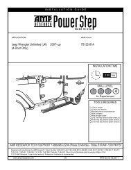
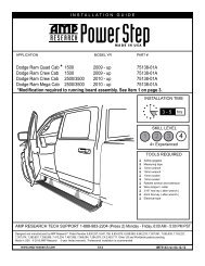
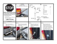
AMP RESEARCH POWER STEP – FORD SUPER DUTYPARTS LIST ANDHARDWAREIDENTIFICATION7 x88 x8910 x81119-02487-90Hex bolt19-02485-90Button head - M1019-02849-90Socket cap screw19-02802-90Socket cap screw10-00115-60Nylock nut12 x819-02488-90U-nut1319-02389-90Large OD Washer14 x819-02486-90Washer (stainless)15 x816-03014-90Washer (black)1619-03353-90Nylock nut17 x219-03339-90<strong>Cab</strong>le tie (11”)1916-03048-90Brake cable bracket18 x2519-02805-90<strong>Cab</strong>le tie (7”)20 x419-03354-90Posi-Tap® connector21 x419-02640-90Grommet22 x419-03302-90LED Lamp22 x819-02989-90Butt connectorwww.amp-research.<strong>com</strong> 4/12IM75134 rev 04.12.12
AMP RESEARCH POWER STEP – FORD SUPER DUTYNOTE: Steps 13-23 are only for model years 2002-2003 with factory remotekeyless entry. For all other model years continue to step 24.2002-2003 model year trucks require that the Greenand Green/Violet wires be routed over to the driverside of the vehicle. Attach extra wire length to bothwires on the harness (Green and Green/Violet), andrun under carpet from passenger side to driver side.Open driver side door and remove sill plate and kickpanel. Lift carpet and pull trigger wires to driver side.13 28 29Remove driver side front door panel. This willrequire removing multiple concealed bolts andpaneling.Door panel removal will require removal of doorlight lens and window corner trim.30 14 15 31Remover speaker and pull back door lining.Insert plastic tubing (for wire routing) and runone trigger wire through to door <strong>com</strong>partment.Then remove the plastic tubing, pulling fromdoor side.(See Detail 18)32 16 Pull back door lining 33 17www.amp-research.<strong>com</strong> 8/12IM75134 rev 04.12.12
AMP RESEARCH POWER STEP – FORD SUPER DUTYDriver Front Door Wiring: Using Posi-Tap connector,connect the supplied additional wire (Red)to front door ajar wire (Yellow w/Black stripe)Driver Door Ajar(Yellow w/Black)Driver Rear Door Wiring: Attach second connectingwire on driver side to rear door ajar wire (LightGreen w/Yellow stripe), found under front door sillplate.CONNECTINGWIREsupplied additional wire18 28 19 29CAUTION: You will fi nd two wires with these colors;the correct wire will ground when the rear door isclosed and OL with the rear door open.Rear Door Ajar(Light Green w/Yellow)Passenger Front Door Wiring: Using Posi-Tapconnector, connect white trigger wire to front doorajar wire (Grey w/Red stripe). Run Yellow triggerwire toward rear.20Power Step TriggerWire (White)Power Step TriggerWire (Yellow)Driver Rear Door Ajar(Light Green w/Yellow)Front Door Ajar(Grey w/Red)30 20 21 31Passenger Rear Door Wiring: Using Posi-Tapconnector, connect Yellow trigger wire to rear doorajar wire (Pink w/Light Blue stripe). This wire isfound rear of junction where wires route under frontpassenger seat.Note: Steps 13-23 are for model years 2002-2003 with factory remote keyless entry (the unlockremote connected to your keys). For vehicleswithout factory remote keyless entry, contact AMPResearch for additional instructions.Yellow Power Steptrigger wireAMP Research Tech Support:1-888-983-2204 (Press 2)rear door ajar(Pink with Light Blue)32 22 23 33www.amp-research.<strong>com</strong> 9/12IM75134 rev 04.12.12
AMP RESEARCH POWER STEP – FORD SUPER DUTYSecure wires and replace kick panel and sill plate.Be careful not to pinch any wires when replacingpanels.Plug in motors (both sides). Route remaining LEDlight wires back towards rear of vehicle.4324 28 25 29Slide mounting T-nut into position. Mount Board andtighten fasteners to 10ft-lbs. Align the end of theboard with the rear edge of the back door.On each side of the vehicle measure from the frontedge of door line on the pinch weld to the specifiedlengths below. Measure at 27” for front LED Lightand 65” for rear LED LIght.2110TORQUE10 ft-lbs.(13.5 Nm)30 2631 27Drill a 9/32” hole through the pinch weld at markedlocations. Debur all holes.27”65”Insert grommet into drilled holes. Insert lamp wiresthrough the grommets. (Silicon lube will help wiresslip through grommets.)212232 28 33 29www.amp-research.<strong>com</strong> 10/12IM75134 rev 04.12.12
AMP RESEARCH POWER STEP – FORD SUPER DUTYAffix lamp to rocker panel surface. Make sure lampis affi xed to a flat, clean surface.Using supplied butt connectors, connect the lampwires. Red to Red, Black to Black2230Close and wrap with conduit and electrical tape.Secure all loose wires with cable ties, with lampwires pulled upward to avoid any wire snagging.31Reinstall the fuse.32334www.amp-research.<strong>com</strong> 11/12IM75134 rev 04.12.12
AMP RESEARCH POWER STEP – FORD SUPER DUTYCheck that all doors activate the Power Step and the LED Lights work when doorsopen and close. Reinstall any remaining trim panels.FINAL SYSTEM CHECKCheck that all doors activate the PowerStep and the LED lights work when doors open and close.NORMAL OPERATION: When the doors open, PowerStep automatically deploys from under the vehicle.When the doors are closed, PowerStep will automatically return to the stowed/retracted position. Note thatthere is a 2-second delay before the PowerStep returns to the stowed/retracted position.CORRECT OPERATION OF LIGHTS: All four lamps will illuminate upon opening any door of vehicle. Lampswill stay on until restowing of both Power Steps or until 5 minutes has expired with the doors open. When thelights timeout after 5 minutes, they can be reillumintated by closing and opening any door of vehicle.www.amp-research.<strong>com</strong> 12/12IM75134 rev 04.12.12
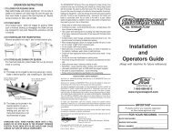
Congratulations on your purchase of thegenuine AMP Research PowerStep!Here’s what you should know...AMP Research PowerStep running boards automatically movewhen the doors are opened to assist entering and exiting the vehicle.Automatic power deploy:The running boards will extend down and out when the doors are opened.Automatic power stow:The running boards will return to the stowed position when the doors are closed. There will be a 2-seconddelay before the running boards move to the stowed position.Automatic stop:If an object is in the way of the moving running board, the running board will automatically stop.To reset, clear any obstruction, then simply open and close the door to resume normal operation.Manually set in the deployed (OUT) position for access to the roof:your foot while at the same time closing the door. To resume normal operation, open and close the door.Maintenance: In adverse conditions, debris such as mud, dirt, and salt may be<strong>com</strong>e trapped in the runningboard mechanism, possibly leading to unwanted noise. If this occurs, manually set the running boards toAvoid spraying the motors directly. After washing, apply silicone spray lubricant to the hinge pivot pins.Do not apply silicone, wax or protectants like Armor All® to the running board stepping surface.Caution! Keep hands away when the running board is in motion.5-YEAR LIMITED WARRANTYAMP RESEARCH warrants this product to be free from defects in material and workmanship for FIVE (5) YEARS FROMDATE OF PURCHASE, provided there has been normal use and proper maintenance. This warranty applies to the originalpurchaser only. All remedies under this warranty are limited to the repair replacement of the product itself, or the repairor replacement of any <strong>com</strong>ponent part thereof, found by the factory to be defective within the time period specified. Thedecision to repair or replace is wholly within the discretion of the manufacturer.for instructions. You must retain proof of purchase and submit a copy with any items returned for warranty work. Upon<strong>com</strong>pletion of warranty work, if any, we will return the repaired or replaced item or items to you freight prepaid. Damageto our products caused by accidents, fire, vandalism, negligence, misinstallation, misuse, Acts of God, or by defective partsnot manufactured by us, is not covered under this warranty.ANY IMPLIED WARRANTIES OF MERCHANTABILITY AND/OR FITNESS FOR A PARTICULAR PURPOSE CREATED HEREBY ARELIMITED IN DURATION TO THE SAME DURATION AND SCOPE AS THE EXPRESS WRITTEN WARRANTY. OUR COMPANY SHALLNOT BE LIABLE FOR ANY INCIDENTAL OR CONSEQUENTIAL DAMAGE.Some states do not allow limitations on how long an implied warranty lasts, or the exclusion or limitation of incidentalor consequential damages, so the above limitations or exclusions may not apply to you. This warranty gives you specificlegal rights, and you may also have other rights that vary from state to state.FOR WARRANTY ISSUES WITH THIS PRODUCT PLEASE CALL AMP RESEARCH CUSTOMER SERVICE 1-800-315-9697WARNINGBe sure to read and precisely follow the provided instructions when installing this product. Failure to do so could place the vehicleoccupants in a potentially dangerous situation. After installing or reinstalling, re-check to insure that the product is properly installed.