WP-4 BVC WP4-50 BVC - Clean My Water
WP-4 BVC WP4-50 BVC - Clean My Water
WP-4 BVC WP4-50 BVC - Clean My Water
- No tags were found...

You also want an ePaper? Increase the reach of your titles
YUMPU automatically turns print PDFs into web optimized ePapers that Google loves.
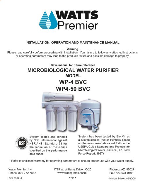
INSTALLATION, OPERATION AND MAINTENANCE MANUALWarningPlease read carefully before proceeding with installation. Your failure to follow any attached instructionsor operating parameters may lead to the products failure and possible damage to property.Save manual for future referenceMICROBIOLOGICAL WATER PURIFIERMODEL<strong>WP</strong>-4 <strong>BVC</strong><strong>WP</strong>4-<strong>50</strong> <strong>BVC</strong>System Tested and certifi edby NSF International againstNSF/ANSI Standard 58 forthe reduction of the claimsspecifi ed on the performancedata sheet.System has been tested by Bio Vir asa Microbiological <strong>Water</strong> Purifi ers basedon the recommendations set forth in theUSEPA Guide Standard and Protocol forMicrobiological <strong>Water</strong> Purifiers (OPP TaskForce Report, 1987).Refer to enclosed warranty for operating parameters to ensure proper use with your water supply.Watts Premier, Inc. 1725 W. Williams Drive C-20 Phoenix, AZ 8<strong>50</strong>27Phone: 800-752-5582 www.wattspremier.com Fax: 623-931-0191P/N: 199218Page 1Manual Edition: 09/30/05
Thank you for your purchase of a state of the art Watts Premier Reverse Osmosis (RO) water treatment system. <strong>Water</strong>quality concerns are becoming more of a focus for the public. You may have heard about contaminants in the drinking water,such as Arsenic, Chromium, Cryptosporidium or Giardia. There may also be some local water issues such as high levels ofLead and Copper. This Watts Premier water treatment system has been designed and tested to provide you with high qualitywater for years to come. The following is a brief overview of the system.Your Reverse Osmosis System:Osmosis is the process of water passing through a semi permeable membrane in order to balance the concentration ofcontaminants on each side of the membrane. A semi permeable membrane is a barrier that will pass some particles like cleanwater, but not other particles like arsenic and lead.Reverse osmosis uses a semi permeable membrane; however, by applying pressure across the membrane, it concentratescontaminants (like a strainer) on one side of the membrane, producing clean water on the other. This is why RO systems produceboth clean drinking water and waste water that is flushed from the system. This reverse osmosis system also utilizes carbonblock filtration technology, and can therefore provide much higher quality drinking water than carbon filtration systems.Your system is a Four Stage RO which is based upon four separate treatment segments within one complete water filtrationsystem. These stages are as follows:Stage 1 – Sediment filter, recommended change 6 months.The first stage of your RO system is a five micron sediment filter that traps sediment and other particulate matterlike dirt, silt and rust which affects the taste and appearance of your water.Stage 2 – Carbon filter, recommended change 6 months.The second stage contains a 5 micron carbon block filter. This helps ensure that chlorine and other materials thatcause bad taste and odor are greatly reduced.Stage 3- Membrane, recommended change 2-5 years.Stage three is the heart of the reverse osmosis system, the RO membrane. This semi-permeable membrane willtake out TDS & Sodium and a wide range of contaminants such as Perchlorate, Chromium, Arsenic, Copper, Lead,as well as Cysts, such as Giardia and Cryptosporidium and much more. Because the process of extracting this highquality drinking water takes time, your RO water treatment system is equipped with a storage tank.Stage 4- State of the Art Microbiological Purifier Filter, recommend change 6 months.The fourth stage consists of a unique microbiological filter, which has been independantly certified to remove alltypes of disease causing microorganisms from the water, including bacteria, viruses and protozoan cysts.System MaintenanceJust because you can not taste it, does not mean that it is not there. Contaminants such as lead, chromium, and arsenic areundetectable to the taste. Additionally, over time if you do not replace the filter elements, other bad tastes and odors willbe apparent in your drinking water.This is why it is important to change out your filter at the recommended intervals as indicated in this system manual. Whenreplacing the filter elements, pay special attention to any cleaning instructions. Should you have any further questions pleaserefer to our website at www.wattspremier.com or call our customer service dept. at 1-800-752-5582.Page 2
With proper installation and maintenance, this system will provide you with high quality water for yearsto come. All of Watts Premier’s water enhancement products are rigorously tested by independentlaboratories for safety and reliability. If you have any questions or concerns, please contact our customerservice department at 1-800-752-5582 (outside USA 623-931-1977) or refer to our on-line trouble shootingat www.wattspremier.com.Table of ContentsOperational Parameters ........................................................................................................................ 4Contents of Reverse Osmosis System .................................................................................................. 4Tools Recommended For Installation .................................................................................................... 4Drill a Hole for the Faucet in a Porcelain Sink ....................................................................................... 5Punch a Hole for the Faucet in a Stainless Steel Sink .......................................................................... 5Wave Faucet Installation ....................................................................................................................... 6Watts Top Mount & Top Mount Monitored Faucet Installation ............................................................... 7Adapta Valve Installation ...................................................................................................................... 8Reverse Osmosis Module Mounting ..................................................................................................... 8Drain Saddle Installation ....................................................................................................................... 9Tank Elbow Installation .......................................................................................................................... 9Blue Tube Connection ......................................................................................................................... 10Green Tube Connection ...................................................................................................................... 103/8” Black Tube Connection .................................................................................................................11How to use Quick Connect Fittings............................................................................................. .........11Red Tube Connection .......................................................................................................................... 12Blue Tube Connection ......................................................................................................................... 12Start up Instructions ............................................................................................................................ 126 Month Maintenance .......................................................................................................................... 13Annual Maintenance ............................................................................................................................ 14Membrane Replacement .................................................................................................................... 14<strong>Clean</strong>ing Flow Restrictor ..................................................................................................................... 15Checking Air Pressure in the Tank ...................................................................................................... 16Procedure for Extended Non-Use ...................................................................................................... 16Trouble Shooting ................................................................................................................................. 17Arsenic Fact Sheet. ............................................................................................................................. 18California Certifi cation ......................................................................................................................... 19Performance Data Sheets ........................................................................................................... 20 & 21One Piece Manifold Drawing ............................................................................................................... 22Parts List ............................................................................................................................................ 22Other Products ........................................................................................................................... 23 - 25Warranty Registration .................................................................................................................. 26 & 27Service Record ................................................................................................................................... 28Limited Warranty ................................................................................................................................ 29Page 3
Operational ParametersOperating Temperatures: Maximum 100°F (37.8°C) Minimum 40°F (4.4°C)Operating Pressure: Maximum 85 psi (6.0 kg/cm 2 ) Minimum 40 psi (2.80 kg/cm 2 )pH Parameters: Maximum 11 Minimum 2Iron:Maximum 0.2 ppmTDS (Total Dissolved Solids) < 1800 ppmTurbidity< 5 NTUHardness: Recommended hardness should not exceed 10 grains per gallon, or 170 ppm. Systemwill operate with hardness over 10 grains but the membrane life will be shortened. (Addition of a watersoftener may lengthen the membrane life.)Note: The operating pressure in your home should be tested over a 24 hour period to attain the maximumpressure. If it is above 85 psi a pressure regulator is recommended and if over 100 psi then a pressureregulator is required. Should you need a gauge to check your pressure, see page 24 (item no. 261003).Note: Reverse Osmosis water should not be run through copper tubing as the purity of the water willleach copper and cause an objectional taste in water and may cause pin holes. Watts supplies specialtymedias that can be used if copper tubing is down stream of the RO. Be sure to follow any state or localregulations.Contents of Reverse Osmosis (RO) System1 Tank – White1 Module – White1 Parts Bag1 Faucet Bag1 Manual and Warranty CardIf any of the items are missing please contact Premier prior to installing.Tools Recommended For Installation1 1/4" Hole Saw Bit for Faucet openingRound Knock out Punch for Stainless Sinks 1 ¼”Adjustable WrenchSharp Knife1 / 2" - 13/16” Open End WrenchesPhillips Screw DriverNeedle Nose Pliers – Adjustable PliersElectric Drill1/8", 1/4" & 3/8" Drill BitsPage 4
Drill a Hole for the Faucet in a Porcelain SinkNote:Most sinks are predrilled with 1 ½” or 1 ¼” diameter hole that you can use for your RO faucet.(if you are already using it for a sprayer or soap dispenser, see step 1).Porcelain sinks are extremely hard and can crack or chip easily. Use extreme caution whendrilling. Premier accepts no responsibility for damage resulting from the installation of faucet.Step 1Step 2Determine desired location for the faucet on your sink and place apiece of masking tape on location where the hole is to be drilled. Markthe center of the hole on the tape.Using a variable speed drill on the slowest speed, drill a 1 / 8” pilot hole throughboth porcelain and metal casing of sink at the center of the desired location.(If drill bit gets hot it may cause the porcelain to crack or chip), use lubricatingoil or liquid soap to keep cool.Step 3Using a 1 ¼” hole saw, proceed to drill the large hole. Keep drill speedon the slowest speed and use lubricating oil or liquid soap to keep thehole saw cool during cutting.Step 4Make sure the surroundings of the sink are cooled before mounting thefaucet to the sink after drilling. Remove all sharp edges.Punch a Hole for the Faucet in a Stainless Steel SinkNote:Step 5If mounting faucet to a Stainless Steel Sink you will need a 1 ¼” HolePunch. The faucet opening should be centered between the backsplash and the edge of the sink, ideally on the same side as the verticaldrain pipe.Drill a ¼” pilot hole. Use a 1/2” Hole Punch and an adjustable wrench topunch the hole in the sink. Change to the 1 1/4” Hole Punch to enlargethe hole.The faucet can now be installed.Page 5
Wave Faucet Installation - Part# 116022Note:Step 6If using the Wave Air Gap Faucet (pictured), a 1 1/4” hole will be required.Gather and identify the Wave faucet pieces.Air Gap Faucet• Faucet assembly• Black Shank Nut• Spacer• GasketStep 7Remove black stem nut and insert the three tubes (air gap faucet)through the white gasket with the groove on the gasket toward thefaucet base.Step 8Insert the three tubes through the 1 1/4” hole in the sink. The whitegasket must be on top side of the sink.Step 9View from under the sink and insert the white plastic spacer asshown.Step 10Thread the black stem nut back onto the white threaded stem andtighten within ¼” of plastic spacer. Check the orientation of the faucetabove the sink and tighten the black plastic washer until white plasticspacer is snug and faucet stands securely on top of the sink.Note:A dripping or gurgling sound may be heard coming from the air gaphole on the faucet or the drain when the system is running. This isnormal and in compliance with UPC (Universal Plumbing Code).Page 6
WATTS Premier Chrome Top Mount & Top Mount MonitoredFaucet InstallationMinimum MaximumMounting Hole Size 1.00” 1.25”Torque on Toggle Bolt 5lb.in. (max)Gather and identify the faucet pieces.Watts FaucetsP/N: 116000 Chrome (Non-Monitored)P/N: 116072 Brushed Nickel (Non-Monitored)P/N: 116074 Chrome (Monitored)Step 6Step 7Step 8Step 9Remove faucet base & faucet spout from their respectiveplastic bags. From above the sink, feed the faucet tubing &toggle bolt down through the 1¼” mounting hole in the sink.Ensure that the soft rubber gasket is uniformly positioned inbetween the base and the top of the sink.Align the faucet base so that the handle is on the right side andthe base is sitting flush on the sink top. Turn the handle down(towards you) to the “ON” position to reveal the tighteningscrew (located where the spout will be inserted). Using aphillips head screwdriver, turn the screw clockwise until thetoggle bolt secures the faucet base snug onto the sink top,do not over torque toggle bolt (5lb.in. max)Once the faucet base is securely fastened to the sink top,insert the faucet spout into the faucet base until it is fullyseated. Turn the handle up (away from you) to the “OFF”position.Completion of faucet installation (tubing connections) will bedone later in this manual. Refer to the Black Tube Connection(page 11), Red Tube Connection (page 12), and Blue TubeConnection (page 12) sections of this manual.Faucet Battery Installation (For Monitored Faucets Only - P/N:116074)Step 10Remove the faucet battery from the plastic bag. Locate the faucet battery compartment drawer on the base of thefaucet. Using a small screwdriver to pry on the notch at the compartment drawer face, slide the drawer out. Insertthe battery into the battery compartment drawer.NOTE: The + side of the battery faces up. The compartment drawer will not slide in if the battery is installedupside down.Once the battery is in place, slide the battery compartment drawer back into the base until it is fl ush.When the battery is fi rst installed, both the red and green lights will fl ash to indicate that both lights are functional.Thereafter, it will fl ash green only when the faucet handle is turned to the “ON” position. When your system is ready tobe serviced (approximately six months) you will see the light fl ash red when the handle is turned to the “ON” position.Refer to the Six Month Maintenance (page 13) section of this manual for fi lter replacement.NOTE: If your water usage is high the red light may activate sooner than six months indicating the need forfilter replacement.This faucet provides an electronic monitor that will tell you when it is time to replace the fi lters in yourwater treatment device. The light indicator will be green for the life of the fi lter, turning red once the lifeof the filter has been reached. This can occur after six months of use, or sooner for heavy water usage.To reset the electronic monitor during replacement of fi lters, simply slide out the battery from the faucetand reinsert. The battery life is expected to last one year, however, for heavy use the battery may needto be replaced sooner. For replacement, look for battery number CR2354 (Watts p/n:116082) which isavailable at your local battery store or contact Watts Premier at 800-752-7782. You can also order onlineat www.wattspremier.com.Page 7
Adapta Valve Installation - Part# 134007Confi guration for 3/8”compression fi ttingsConfi guration for 1/2”compression fi ttingsHotSupplyColdSupplyStep 11Turn off the cold water supply to the faucet by turning the angle stop valve completely off.Step 12Attach adapta valve as illustrated in the three photos above, choosing the confi guration thatfi ts your plumbing. The green tube from inlet side of RO module will be cut to length andattached later in the installation.Caution: <strong>Water</strong> supply line to the system must be from the cold water supply line only. Hot water willseverely damage your system.Reverse Osmosis Module MountingStep 13Determine best location for the RO module to be mounted to allow forfuture system maintenance. The parts bag has 2 self tapping screws.Using a phillips screwdriver, screw them into the cabinet wall 6” apartand 16” from the bottom of the cabinet.Note: Do not cut any RO system tubes at this timePage 8
Drain Saddle Installation - Part# 164016Drain Saddle fits standard 1 ¼” – 1 ½” drain pipesStep 14Step 15Gather the pieces of the drain saddle1 Black compression nut1 Semicircle bracket with opening2 Screws1 Foam washer2 Nuts for screws1 Semicircle bracketThe small square black foam gasket with a circle cut out of the middlemust be applied to the inside of the drain saddle. Remove sticky tapebacking and stick to the drain saddle as shown.Step 16 Drill a ¼” hole through the drain pipe at least 1 ½” above the nut of theP-trap to allow for the removal of the P-trap if necessary. Assemblethe drain saddle around the drain pipe. Position the drain saddle overthe drilled hole in pipe. Insert screw driver into the opening of thedrain saddle and align with drilled hole in drain pipe. Using Philipsscrew driver tighten screws evenly and securely on both sides of thedrain saddle. Attach black compression nut, but do not tighten atthis time. The black tubing will be installed later.Caution:Do not over tighten the screws. It may crack the drain saddle.Tank Elbow Installation - Part# 12<strong>50</strong>32Step 17Wrap (7 to 12 turns) Tefl on tape clockwise around the male pipethreads (MPT) on the Stainless Steel fi tting on top of the tank.Note:Do not let the tape cover the opening.Step 18Thread the plastic elbow (supplied in the parts bag) onto the stainlesssteel connection on the top of tank. Tighten using an adjustablewrench. Do not over tighten as plastic could crack.Caution: Do not Teflon tape the plastic elbow threads as this may causeleaks.Page 9
Connect Blue Tube from TANK port on RO Module to the TankStep 19Position tank in desired location. Stand it upright or lay it on itsside (using the black plastic stand). Measure the blue tube fromthe RO module port marked TANK over to the tank and cut it todesired length.Step 20Insert the blue 3/8” tube into the compression nut as far as it willgo. Tighten the compression nut securely with a wrench.Green Tube ConnectionStep 21Insert the green tube into the ¼” opening on the adapta valve untilit stops. Slide nut and sleeve down and thread onto the male pipethreads. Use a ½” wrench to securely tighten.Step 22Remove a brass nut, plastic sleeve and brass insert from the partsbag. Place nut on the tube fi rst, then the sleeve (Small taper endof sleeve must point to the end of tube) and then insert the brassInsert into the end of the tube.Step 23Connect the green tube from the RO module to the adapta valvethat is connected to the Angle Stop Valve. Leave enough tube soit is not kinked and cut the tube to desired length.Adapta Valve - Part # 134007Page 10
3/8” Black Tube Connection from faucetNote:Step 24Step 25Note:The tubing must be as SHORT and STRAIGHT as possibleto the drain saddle, making a downward slope from moduleto drain saddle to allow for proper drainage.Measure the black tube from faucet to the black drain saddleand make a straight cut through tube.Remove black plastic nut from drain saddle. Slip black tubethrough black nut. Insert black tube into the opening in thedrain saddle and hand tighten the black nut, and add 1/4 turnwith a wrench.This is a gravity fed line, if there is any bend or dip in the tubethe rinse water will not fl ow into the drain properly. <strong>Water</strong> willback up and come out the air gap hole in the back of the faucetbase.How to Use the Quick Connect Fittings on the RO ModuleTo make a connection, the tube is simply pushed into the fi tting. Place a piece of tape 1/2” from endof tube to indicate how far the tube should be inserted. The unique patented John Guest® lockingsystem holdsCut the tube square. It is essential that the outside diameterbe free of score marks and that burrs and sharp edges beremoved before inserting into fi tting.Fitting grips before it seals. Ensure tube is pushed into thetube stop.Push the tube into the fitting, to the tube stop. The collet(gripper) has stainless steel teeth which hold the tube firmlyin position while the O-ring provides a permanent leak proofseal.Pull on the tube to check that it is secure. It is a good practiceto test the system prior to leaving site and /or before use.To disconnect, ensure the system is depressurized beforeremoving the tube. Push in collect squarely against face offi tting. With the collect held in this position, the tube can beremoved. The fi tting can then be reused.Page 11
Connect the Red Tube from Faucet to RO ModuleStep 26Insert the red 1/4” tube from the faucet into the port on the modulemarked “DRAIN”. Make sure the tube is pushed in all the way tothe tube stop.Connect the Blue Tube from the Faucet to RO ModuleStep 27Insert the blue 3/8” tube from the faucet into the port on the modulemarked “FAUCET”. Make sure the tube is pushed in all the way tothe tube stop.Start up InstructionsStep 1Turn on the incoming cold water at the angle stop valve. Open the needle valve on the brassAdapta Valve by turning counter clockwise. Check the system for leaks and tighten any fi ttingas necessary. (Check frequently over the next 24 hours to ensure no leaks are present).Step 2Step 3Step 4Step 5Step 6NOTE:Open the RO faucet and leave it open until water begins to trickle out, (it will come outslowly).After water trickles out of the faucet, close RO faucet so the tank will fi ll with water. The tankwill take 6 to 10 hours at fi rst to fi ll completely depending on the size of themembrane, local water temperature and pressure.After the Tank has fi lled, open the RO Faucet to fl ush the Tank completely to remove carbonparticles from fi nal fi lter. Repeat this step two more times. The fourth tank can be used fordrinking. Note: The fl ushing of the tank 3 times is only necessary during initial installation.This should take about a day to complete.If system is connected to an Ice Maker, turn the Ice Maker off until fl ushing is complete andthe tank has refi lled. The system should have an in-line valve installed before the Ice Makerso it can be closed to prevent water fl owing to the Ice Maker. Your tank must be allowed tofi ll up in order for the unit to shut off. (If you are installing an Ice Maker Kit, tee off after thefi nal fi lter).Register warranty by mail, phone, or internet. Watts Premier uses this information only toprovide a fi lter change reminder service. Pre-fi lters should be changed every six months. Youmay register your warranty via our website at www.wattspremier.com or call 1-800-752-5582(within USA only).Your reverse osmosis system contains replaceable treatment components that are critical foreffective contaminant reduction. Periodic inspection and following proper system maintenanceis critical for continued performance.Page 12
6 Month System MaintenanceSystemStageType of FilterPart NumberStage 1 Sediment Filter (Change every 6 months) 104017Stage 2 Carbon Block Filter (Change every 6 months) 101009Stage 3RO Membrane(Change every 2-5 years)110009 or 110019(24GPD) (<strong>50</strong>GPD)Stage 4 Microbiological Filter (Change every 12 months) 101003Step 1Step 2Step 3Step 4Step 5Turn off incoming water supply to the RO by turning theneedle valve on the adapta valve clockwise. (The green tubeis connected to the adapta valve.)Open RO Faucet to allow water to drain from the tank untilcompletely empty. <strong>Water</strong> can be saved in a container fordrinking or to rinse system parts.Let system sit for a few minutes after tank is empty todepressurize before attempting to remove fi lter housings.For more leverage, leave RO module attached to wall ofcabinet. If you are unable to access the module you mayremove it to change fi lters. Starting with Stage 1, remove andempty water, then discard fi lter. Continue on to the 2 nd Stageand/or annual change of 4 th Stage.<strong>Clean</strong> all fi lter housings (bowls) with a mild soap solutionand rinse with water. Check O-rings and lubricate with watersoluble lubricant. KY Jelly® , Canola oil and other water basedlubricants can be used, petroleum based lubricants (such asIncoming <strong>Water</strong> SupplyStage 1Sediment Filter Sediment FilterStage 3MembraneStage 2Carbon BlockCarbon BlockStage 4MicrobiologicalFilterMicrobiologicalFilterStep 6Caution:Step 7Step 8The sediment fi lter has a cloth like appearance. It should bein the 1 st Stage on the side with tubing connections.Check O-rings to make sure they are still in place.Insert the Carbon Block fi lter (fi lter has white end caps and agasket on each end) into Stage 2.If doing annual replacement of Stage 4, insert the MIcrobiologicalFilter into the last housing (fi lter with the double O-rings onNote: If also doing the annual maintenance at this time continueto Step 2 on page 14.Step 9Turn water on to the unit by turning the needle valve on theadapta valve counter clock wise.Step 10Open RO faucet and leave open until water begins to trickleout. Close RO faucet to allow tank to fi ll with water.Page 13
Annual MaintenanceStep 1Step 2Step 3Step 4Step 5Step 6Annual sanitizing of unit is recommended. Turn off incoming water supply. Remove sediment& carbon fi lters from fi lter housings.Open Membrane vessel and remove the membrane from the membrane vessel. Replaceempty membrane vessel onto the unit.Leave filters out, replace the last two (of three) empty filter housings (hand tight) onto unit. Measure& pour either 1/2 cup of 3% hydrogen peroxide or 2 tablespoons of common household bleachinto the 1st filter housing and hand tighten onto unit.Turn on incoming water supply. Wait 1 minute for the unit to pressurize. Turn on the RO faucetand let the water run for 30 seconds then turn off the RO faucet . Let the unit repressurizefor 2 minutes. Open RO faucet again and let the water run for 5 more minutes.Turn off incoming water supply and make sure tank is completely drained. Refer to 6 monthsfilter change to now install new filters. Make sure to insert RO membrane back into the manifoldvessel.Open membrane vessel and insert the membrane back into the manifold, making sure not tokink the O-Ring. Tighten the membrane vessel back on the RO unit.Step 7Turn on incoming water supply. Let tank fi ll for 2-3 hours. Check for leaks and drain tankone last time.Membrane ReplacementMembranes have a life expectancy of between 2 and 5 years, depending on theincoming water conditions and the amount of use of the RO system.Normally, a membrane would be replaced during a semiannual or annual fi lterchange. However, if at any time you notice a reduction in water production oran unpleasant taste in the reverse osmosis water, it could be time to replacethe membrane. A water sample may be sent to Watts Premier for a free test ora TDS (total dissolved solids) monitor can be purchased from Watts Premier totest the incoming and reverse osmosis water at home.To send a water sample, using 2 clean containers put ½ cup of tap water in onecontainer and ½ cup of reverse osmosis water in 2nd clean container. Clearlymark each container. Watts Premier will test the water and call or mail you theresults.Step 1Step 2Turn off the cold water supply and open the RO faucet to drain thetank.Remove the membrane vessel on top of the unit by turning the vesselcounter clockwise to loosen.Page 14
Step 3Pull fi rmly on the membrane to remove from the housing anddiscard.Step 4Unwrap new membrane and lubricate the o-rings with water solublelubrication such as KY Jelly ® before inserting into housing. Insertend with the two black O-rings into the cap. Twist the membrane asyou push fi rmly into the cap.(25 GPD membrane part #: 110009)(<strong>50</strong> GPD membrane part #: 110019)Step 5Replace the vessel onto the cap by turning clockwise. Tightensecurely.<strong>Clean</strong>ing the Flow RestrictorStep 6The fl ow restrictor plug must be cleaned each time you change theMembrane. Remove the existing fl ow restrictor with a screwdriver.Step 7Wash with soap and water and rinse. Reinsert the fl ow restrictorplug and tighten until the head is fl ush with module.Step 8 Follow the Start Up Instructions on page 12.Page 15
Check Air Pressure in the TankNote:Check air pressure when tank is empty of water!Check air pressure in the tank when you notice a decrease in availablewater from the RO system.Step 1Step 2It is recommended that you drain the tank of water, and then pumpup the RO tank in order to ensure all water is out of the tank. Aircan be added with a bicycle pump.Once all water in the tank is purged out, check air pressure of thetank. If you added air to the tank, it will be higher than 5 - 7 psi.Allow air out until you have 5 - 7 psi in the tank.Procedure for Extended Non-UseIf the system will not be used for an extended period (more than 2months), shut the system down and remove the membrane. Placethe membrane in a sealed plastic bag with a few drops of RO waterand place in your refrigerator.For restart, follow annual sanitization procedures.Page 16
TROUBLE SHOOTINGProblem Cause Solution1. Low/Slow Production Low <strong>Water</strong> Pressure Assure a minimum of 40 psi incoming water pressure.Premier sells a booster pump if home water pressure islow. Maker sure water supply is turned on and AdaptaValve is all the way openCrimps in tubingCheck tubing and straighten or replace as necessary.Clogged pre-fi ltersReplace pre-fi lters.Fouled membraneReplace membrane and clean fl ow restrictor.2. Milky colored <strong>Water</strong> Air in system Air in the system is a normal occurrence with initial startup of the RO system. This milky look will disappearduring normal use within 1-2 weeks. If condition reoccursafter fi lter change, drain tank 1 to 2 times.3. <strong>Water</strong> constantly Low water pressure See #1 Aboverunning unit will notshut off Fouled membrane Replace membraneHigh water pressureCheck incoming water pressure to make sure it does notexceed 100 psi. A presser relief valve may be necessary.High air pressure in tank Empty storage tank of water. Set tank air pressure to 5psi. See previous page.4. Noise from faucet or drain Air gap faucet Inherent sound with air-gap faucets.Location of drain saddle See diagram for proper location of drain saddle.Higher capacity membrane Normal with high capacity membraneHigh water pressureCheck incoming water pressure to make sure it does notexceed 100 psi. A presser relief valve may be necessary.5. Faucet leaks from Crimp or loop in drain line Straighten black 3/8 drain tube. Cut off any excess tubingthe air gap feature Drain tube clogged/restricted Caused from dishwasher or garbage disposal.Disconnect the 3/8” black tube at the drain, clean the 3/8”black tube out with a wire, then reconnect.6. Small amount of water in System just starting up Normally it takes 6-10 hours to fi ll tank. Note: Lowstorage tankpressure and/or temperature can drastically reduceproduction rate.Low water pressureSee #1 AboveToo much air in tankAdd air if below 5 psi and bleed if above 5 psi. Checkonly when tank is empty of water. See previous page.7. <strong>Water</strong> leaks from the Not properly tightened. Tighten the bowlfi lter housing Missing or kinked O-ring Turn off the water supply. Release the pressure, removebowl and replace the O-ring. (p/n 113043). Make surethe O-ring is seated in the fi lter bowl properly beforereinstalling the fi lter bowl.Page 17
Arsenic Fact SheetArsenic (As) is a naturally occurring contaminant found in many ground waters. Arsenicin water has no color, taste or odor. It must be measured by an arsenic test kit or lab test.Public water utilities must have their water tested for arsenic. You can obtain the resultsfrom your water utility contained with in your consumer confi dence report. If you have yourown well, you will need to have the water evaluated. The local health department or thestate environmental health agency can provide a list of test kits or certifi ed labs.There are two forms of arsenic: pentavalent arsenic (also called As (V), As (+5))and trivalentarsenic (also called As (III), As (+3)). In well water, arsenic may be pentavalent, trivalent,or a combination of both. Although both forms of aresenic are potentially hazardous toyour health, trivalent arsenic is considered more harmful than pentavalent arsenic.RO systems are very effective at removing pentavalent arsenic. A free chlorine residualwill rapidly convert trivalent arsenic to pentavalent arsenic. Other water treatmentchemicals such as ozone and potassium permanganate will also change trivalent arsenicto pentavalent arsenic. A combined chlorine residual (also called chloramine) may notconvert all the trivalent arsenic. If you get your water from a public water utility, contactthe utility to fi nd out if free chlorine or combined chlorine is used in the water system.This Watts Premier reverse osmosis system is designed to remove up to 98% of pentavalentarsenic. It will not convert trivalent arsenic to pentavalent arsenic. Under laboratory standardtesting conditions, this system reduced 0.30 mg/L (ppm) pentavalent arsenic to under 0.010mg/L (ppm) (the USEPA standard for drinking water). Actual performance of the systemmay vary depending on specifi c water quality conditions at the consumer’s installation.The RO component of this Watts Premier reverse osmosis system must be maintainedaccording to its recommended maintenance cycle. Specifi c component identifi cation andordering information can be found in the installation/operation manual maintenance section,by phone at 1-800-752-5581 or online www.wattspremier.com.California Proposition 65 WarningWARNING: this product contains chemicals know to the State of California to cause cancerand birth defects or other reproductive harm. (Installer: California law requires that thiswarning be given to the consumer). For more information: www.wattsind.com/prop65.Page 18
California CertificationPage 19
Performance Data Sheet<strong>WP</strong>-4<strong>BVC</strong>Watts Premier Inc.1725 W. Williams Drive C-20Phoenix, AZ 8<strong>50</strong>27 USAGENERAL USE CONDITIONS:1. System has been independantly tested for the removal of microbiologically contaminated water. The system is not intended for the treatment of water that has anobvious contamination source, such as raw sewage. This system is not intended to convert wastewater to microbiologically safe drinking water.2. Operating Temperature: Maximum: 100°F (40.5°C) Minimum: 40° (4.4°)3. Operating <strong>Water</strong> Pressure: Maximum: 85 psi (6.0kg/cm2) Minimum: 40 psi (2.8kg/cm2)4. pH 2 to 115. No iron present in incoming feed water supply.6. Hardness of more than 7 grains per gallon (120 ppm) may reduce RO membrane life expectancy.7. Recommend TDS (Total Dissolved Solids) not to exceed 1800 ppm.DescriptionStage 1: Sediment Filter Part# 104017Replace6 MonthsDescriptionReplaceStage 4 - Microbiological Filter Part# 101003 12 MonthsStage 2: Carbon Filter Part# 101009 6 MonthsStage 3: RO Membrane 25 GPD Part# 110009 2 to 5 YearsDepending upon incoming feed water conditions replacement timeframe may vary.This system has been tested according to NSF/ANSI 58 for reduction of the substances listed below. The concentration of the indicated substances in waterentering the system was reduced to a concentration less than or equal to the permissible limit for water leaving the system as specified in NSF/ANSI 58. Thissystem has been tested for the treatment of water containing pentavalent arsenic (also known as As (V), As (+5), or arsenate) at concentrations of 0.30 mg/L orless. This system reduces pentavalent arsenic, but may not remove other forms of arsenic. This system is to be used on water supplies containing a detectable freechlorine residual at the system inlet or on water supplies that have been demonstrated to contain only pentavalent arsenic. Treatment with chloramine (combinedchlorine) is not sufficient to ensure complete conversion of trivalent arsenic to pentavalent arsenic, Please see the Arsenic Facts section of the Performance DataSheet for further information.Avg. In. Avg. Eff. % Reduction pH Pressure Max Eff. Inf. challenge Max Allowable(mg/L) (mg/L) mg/L concentration concentrationmg/Lmg/LBacteria* 99.9999%Virus* 99.99%Arsenic (Pentavalent) 334.62 ug/L 5.039 ug/L 98.4% <strong>50</strong>psi 19 ug/L 0.30±10% 0.010 mg/LBarium Reduction 10.2 0.13 98.7% 7.24 <strong>50</strong>psi 0.27 10.0±10% 2.0Cadmium Reduction 0.031 0.0001 99.7% 7.49 <strong>50</strong>psi 0.0009 0.03±10% 0005Chromium (Hexavalent) 0.30 0.006 98.0% 7.24 <strong>50</strong>psi 0.013 0.03±10% 0.1Chromium (Trivalent) 0.30 0.003 99.0% 7.24 <strong>50</strong>psi 0.008 0.03±10% 0.1Copper Reduction 3.0 0.04 98.7% 7.64 <strong>50</strong>psi 0.06 3.0±10% 1.3Cysts 222,077#/ml 10 #/ml 99.99% <strong>50</strong>psi 58 minimum <strong>50</strong>,000/mL N/AFluoride Reduction 8.0 0.33 95.9% 7.49 <strong>50</strong>psi 0.47 8.0±10% 1.5Lead Reduction 0.15 0.004 97.3% 7.49 <strong>50</strong>psi 0.008 0.15±10% 0.0107Perchlorate 0.10 0.003 96.5% 7.39 <strong>50</strong> psi 0.005 mg/L 0.10±10% 0.006Radium 226/228 25pCi/L 5pCi/L 80.0% 7.24 <strong>50</strong>psi 5pCi/L 25pCiL±10% 5pCiLSelenium 0.10
Performance Data Sheet<strong>WP</strong>4-<strong>50</strong><strong>BVC</strong>Watts Premier Inc.1725 W. Williams Drive C-20Phoenix, AZ 8<strong>50</strong>27 USAGENERAL USE CONDITIONS:1. System has been independantly tested for the removal of microbiologically contaminated water. The system is not intended for the treatment of water that has anobvious contamination source, such as raw sewage. This system is not intended to convert wastewater to microbiologically safe drinking water.2. This system is acceptable for treatment of influent concentrations of no more than 27 mg/L nitrate and 3 mg/L nitrite in combination measured as N and iscertified for nitrite/nitrate reduction only for water supplies with a pressure of 280 kPa (40 psig) or greater. If your water supply is under 40 psi Watts Premierrecomends the use of a RO booster pump for proper operation.3. Operating Temperature: Maximum: 100°F (40.5°C) Minimum: 40° (4.4°)4. Operating <strong>Water</strong> Pressure: Maximum: 85 psi (6.0kg/cm2) Minimum: 40 psi (2.8kg/cm2)5. pH 2 to 116. No iron present in incoming feed water supply.7. Hardness of more than 10 grains per gallon (170 ppm) may reduce RO membrane life expectancy.8. Recommend TDS (Total Dissolved Solids) not to exceed 1800 ppm.DescriptionStage 1; Sediment Filter Part# 104017Replace6 MonthsDescriptionReplaceStage 4 - Microbiological Filter Part# 101003 12 MonthsStage 2: Carbon Filter Part# 101009 6 MonthsDepending upon incoming feed water conditions replacement timeframe may vary.Stage 3: RO Membrane <strong>50</strong> GPD Part# 110019 2 to 5 yearsThis system has been tested according to NSF/ANSI 58 for reduction of the substances listed below. The concentration of the indicated substances in waterentering the system was reduced to a concentration less than or equal to the permissible limit for water leaving the system as specified in NSF/ANSI 58. Thissystem has been tested for the treatment of water containing pentavalent arsenic (also known as As (V), As (+5), or arsenate) at concentrations of 0.30 mg/L orless. This system reduces pentavalent arsenic, but may not remove other forms of arsenic. This system is to be used on water supplies containing a detectable freechlorine residual at the system inlet or on water supplies that have been demonstrated to contain only pentavalent arsenic. Treatment with chloramine (combinedchlorine) is not sufficient to ensure complete conversion of trivalent arsenic to pentavalent arsenic, Please see the Arsenic Facts section of the Performance DataSheet for further information.Avg. In. Avg. Eff. % Reduction pH Pressure Max Eff. Inf. challenge Max Allowable(mg/L) (mg/L) mg/L concentration concentrationmg/Lmg/LBacteria* 99.9999%Virus* 99.99%Arsenic (Pentavalent) 334.62 ug/L 5.039 ug/L 98.4% <strong>50</strong>psi 19 ug/L 0.30±10% 0.010 mg/LBarium Reduction 10.2 0.13 98.7% 7.24 <strong>50</strong>psi 0.27 10.0±10% 2.0Cadmium Reduction 0.031 0.0001 99.7% 7.49 <strong>50</strong>psi 0.0009 0.03±10% 0005Chromium (Hexavalent) 0.30 0.006 98.0% 7.24 <strong>50</strong>psi 0.013 0.03±10% 0.1Chromium (Trivalent) 0.30 0.003 99.0% 7.24 <strong>50</strong>psi 0.008 0.03±10% 0.1Copper Reduction 3.0 0.04 98.7% 7.64 <strong>50</strong>psi 0.06 3.0±10% 1.3Cysts 222,077#/ml 10 #/ml 99.99% <strong>50</strong>psi 58 minimum <strong>50</strong>,000/mL N/AFluoride Reduction 8.0 0.33 95.9% 7.49 <strong>50</strong>psi 0.47 8.0±10% 1.5Lead Reduction 0.15 0.004 97.3% 7.49 <strong>50</strong>psi 0.008 0.15±10% 0.0107Nitrite and Nitrate 29.2 6.6 77.3% 7.64 <strong>50</strong>psi 10.0 3.0±10% 10.0Nitrate Reduction 26.3 6.1 76.8% 7.64 <strong>50</strong>psi 10.0 3.0±10% 10.0Nitrite Reduction 2.8 0.5 82.1% 7.64 <strong>50</strong>psi 0.77 3.0±10% 1.0Perchlorate 0.10 0.003 96.5% 7.39 <strong>50</strong> psi 0.005 mg/L 0.10±10% 0.006Radium 226/228 25pCi/L 5pCi/L 80.0% 7.24 <strong>50</strong>psi 5pCi/L 25pCiL±10% 5pCiLSelenium 0.10
Page 22
Other Products from Watts PremierWatts Premier has other fi ne water fi ltration products and accessories to enhance your water and tocompliment your existing RO System. Listed on the next several pages are only a few of the items weoffer. Visit our website at www.wattspremier.com or call our Customer Service Representatives at1-800-752-5582 (inside USA) 1-623-931-1977 (outside USA) for more products.<strong>WP</strong>-4 <strong>BVC</strong> Filter Replacement Kit (5 pack)Compatible with Watts Premier 4 Stage Reverse Osmosis and water fi ltrationsystems. These fi lters provide an extra level of fi ltration by allowing for morecontact between the carbon media and your water. This kit includes the uniqueMicrobiological fi lter which is independantly certifi ed to remove all types ofdisease causing microorganisms.Part No. 560036*$41.95/KitWatts Premier Hot <strong>Water</strong> Recirculation PumpBring convenience and saving to your home, giving you hot water instantly atevery faucet, when you need it. This unique product is easy to install and notonly provides you with the convenience of hot water when you need it, butsaves an average of over 11,000 gallons per year.Part No. <strong>50</strong>0800*$229.99 each3/8” Ice Maker Kit for RO and Filtration3/8 inch connection includes 30 feet tubing, ball valve, and fi ttings.Part No. <strong>50</strong>0010*$ 17.00/eaWatts Premier Ice Maker Kit - High effi ciency replaceable fi lter that can lastup to 3 years or 10,000 gallons. Perfect for residential and commercial icemakers as well as refrigerators, drinking fountains, coffee & tea brewers,motor homes and campers. Reduces chlorine taste and odor.Part No. <strong>50</strong>0327*$36.95/ea*All prices subject to change without notice.Page 23
Wave Faucets by Watts Premier allow for a variety of choices tomatch your kitchen decor.Available colors include:Part No. 116026 Stainless SteelPart No. 116022 ChromePart No. 116010 WhitePart No. 116002 Black on chromeTop Mount Faucets by Watts PremierThese attractively designed faucets feature a long reach spout to complimentall styles of kitchen decor. The unique top mount design allows for easy abovecounter installation. The Monitored version of this faucet has an LED light thatturns red to notify you for fi lter replacement.Part No. 116000 - Chrome (Non-Monitored)*$49.95/ea116072 - Brushed Nickel (Non-Monitored) *$59.95/ea116074 - Chrome (Monitored) *$69.95`/eaWhole House FilterGreat for sediment problems such as in well water supply or areas where dirtand rust particles are a problem. Includes three <strong>50</strong> micron sediment fi lters andwrench(3/4” ports)Part No. <strong>50</strong>0223*$86.95/eaReplacement filterPart No. 304007*$ 7.95/ea<strong>Water</strong> Pressure GaugeThis gauge mounts onto your outside hose connection to accurately show yourhome’s water pressure up to 300 psi. A red needle shows peak overnight pressure,which may exceed readings during the day. High pressure readings mayindicate the need for a pressure regulator to prevent damage to appliances.Part No. 261003*$14.95/eaPocket Total Dissolved Solids (TDS) MonitorTest water electronically to verify reverse osmosis membrane effectiveness.Carrying case included.Part No. 273001*$39.95/eaBall Valve AdaptorEliminates the need to drain the tank during normal fi lter changes. This easy toinstall valve attaches to the top of your water tank. The tank should always bedrained after the membrane is changed.Part No. 134023*$ 5.00/ea*All prices subject to change without notice.Page 24
Removing chlorine from your showerSpecial Chlorgon & KDF media – More effective then carbon medias withhot water applications in the removal of the following.√ Free Chlorine (CL-)√ Combined Chlorine (Sodium Hypochlorite)√ Hydrogen Sulfi de (Rotten egg smell)√ Plus, its pH balanced.√ Iron oxide (rust water)√ Dirt, sediment√ OdorsDeluxe Shower Handle with Built in FilterReplacement filters2PK5-Way Massaging Spray72” Reinforced HoseHigh Strength BracketTriple Plated FinishReversible Filter Cartridge (Model HHC)Cartridge Life Rating: 3 monthsPart No. 107090 WHITE *$42 .95Part No. 107091 CHROME *$44.95 Part No. 107075 *$14.95/pkShower Falls Deluxe Shower Handle with Built in FilterCurved Ergonomic Shower HandleFilter Handle ExtensionReplacement filters 2PKDual Swivel AdjustmentUltra Deluxe 5 Way Massaging Spray72” Reinforced HoseChrome Plated Brass Bracket & Swivel Ball ExtensionTriple Plated FinishReversible Filter Cartridge (Model HHC)Cartridge Life Rating: 3 monthsPart No. 107095 CHROME *$55.95Part No. 107075 *$14.95/pkAll-In-One reversible High-Flow FilterDeluxe 5-Way Massaging SprayReplacement filterSoft-Touch Adjustment PadsAnti-Scaling Spray NozzleHigh Strength HousingTriple Plated FinishCartridge Life Rating: 6 monthsPart No. 107098 White/Chrome *$47.<strong>50</strong> Part No. 107080 *$18.95/eaPart No. 107099 White/Gold *$45.00*All prices subject to change without notice.Page 25
WARRANTY REGISTRATIONThank you for selecting Watts Premier for your water fi ltration needs.4 Ways to Register1. Online at www.wattspremier.comRegister your product online and receive a 5% discount on your next online order, Plus receive reduced shipping.2. Call in your information 1-800-752-5582Call and we will enter your information.3. Fax in your information 623-931-0191Fax this form directly to us.4. Mail in the information.Please complete the form below. Mail to: Watts Premier1725 W. Williams Dr. C-20Phoenix, AZ 8<strong>50</strong>27Registering willinsure youreceive WattsFREEFilterReminderServiceWatts Premier Inc. is concerned for the safety of your personal information. Watts Premier collects personal information when you register withWatts Premier. This information is stored in our data base and we do not rent, sell, or share personal information with other people or nonaffi liatedcompanies. We reserve the right to send you certain types of communications such as direct mail, email, or by telephone relating to our productsor products that you have purchased. We limit access to your personal information to those employees who will directly provide you with servicesor products in order to do their jobs. We want to offer you four ways to communicate with us. 1.Online, 2.Fax, 3.Telephone, and 4. Mail the formbelow. By registering your product you will receive the full benefi t of our warranty. Watts Premier will also send you a semiannual fi lter changereminder beginning six months from date of installation. To insure the highest quality of your water, filters should be replaced every 6 months. Ifyou have any questions or comments please give us a call at 1-800-752-5582 M-F 8:00am -5:00pm MST.First Name:_________________________ Last Name:____________________________Address: ________________________________________ City: ____________________State: _______________________________________ Zip Code: ___________________Country: USA CANADA MEXICO OTHER ____________Phone # ______-__________ -__________Date of Purchase: ___________________Email Address: ______________________Date of Install: _______________________Installed By: SELF Plumbing Professional Where Purchased: ____________Model Number: _______________________Serial Number: ____ __________XXXXX - XXXXXXWatts Premier, Inc. 1725 W. Williams Drive C-20 Phoenix, AZ 8<strong>50</strong>27Phone: 800-752-5582 www..wattspremier.com Fax: 623-931-0191Page 26
WARRANTY REGISTRATIONPlease Fill out and keep for your RecordsFirst Name:_________________________ Last Name:____________________________Address: ________________________________________ City: ____________________State: _______________________________________ Zip Code: ___________________Country: USA CANADA MEXICO OTHER ____________Phone # ______-__________ -__________Date of Purchase: ___________________Email Address: ______________________Date of Install: _______________________Installed By: SELF Plumbing Professional Where Purchased: ____________Model Number: _______________________Serial Number: ____ - __________XXXXX - XXXXXXInsert into envelope and return to Watts PremierWatts Premier1725 W. Williams Dr. C-20Phoenix, AZ 8<strong>50</strong>27Page 27
Service RecordSerial No. _____________________Date of Purchase:__________ Date of Install:___________ Installed by:__________________Date1st stageSediment(6 months)2 nd stageCarbon(6 months)3rd stageMembrane(2-5 years)4th stageMicrobiological(1 year)NOTES:Page 28
Limited WarrantyWhat your Warranty Covers:If any part of your WATTS PREMIER Reverse Osmosis System is defective in workmanship (excluding replaceable filtersand membranes), return unit after obtaining a return authorization (see below), less tank, within 3 year of originalretail purchase, WATTS PREMIER will repair or, at WATTS PREMIER’S option, replace the system at no charge.How to obtain Warranty Service:For warranty service, call 1-800-752-5582 for a return authorization number. Then, ship your Reverse Osmosis unit(less tank) to our factory, freight and insurance prepaid, with proof of date of original purchase. Please include anote stating the problem. Premier will repair it, or replace it, and ship it back to you prepaid.What this warranty does not cover:This warranty does not cover defects resulting from improper installation, (contrary to WATTS PREMIER’s printedinstructions), from abuse, misuse, misapplication, improper maintenance, neglect, alteration, accidents, casualties,fire, flood, freezing, environmental factors, water pressure spikes or other such acts of God.This warranty will be void if defects occur due to failure to observe the following conditions:1. The Reverse Osmosis System must be hooked up to a potable municipal or well cold water supply.2. The hardness of the water should not exceed 7 grains per gallon, or 120 ppm.3. Maximum incoming iron must be less than 0.2 ppm.4. The pH of the water must not be lower than 2 or higher than 11.5. The incoming water pressure must be between 40 and 100 pounds per square inch.6. Incoming water to the RO cannot exceed 105 degrees F (40 degrees C.)7. Incoming TDS/Total Dissolved Solids not to exceed 1800 ppm.8. Do not use with water that is microbiologically unsafe or of unknown quality withoutadequate disinfection before or after the system.This warranty does not cover any equipment that is relocated from the site of its original installation.This warranty does not cover any equipment that is installed or used outside the United States of America and Canada.LIMITATIONS AND EXCLUSIONS:WATTS PREMIER WILL NOT BE RESPONSIBLE FOR ANY IMPLIED WARRANTIES, INCLUDING THOSE OF MERCHANTABILITYAND FITNESS FOR A PARTICULAR PURPOSE. PREMIER WILL NOT BE RESPONSIBLE FOR ANY INCIDENTAL ORCONSEQUENTIAL DAMAGES, INCLUDING TRAVEL EXPENSE, TELEPHONE CHARGES, LOSS OF REVENUE, LOSS OFTIME, INCONVENIENCE, LOSS OF USE OF THE EQUIPMENT, AND DAMAGE CAUSED BY THIS EQUIPMENT AND ITSFAILURE TO FUNCTION PROPERLY. THIS WARRANTY SETS FORTH ALL OF PREMIER’S RESPONSIBILITIES REGARDINGTHIS EQUIPMENT.OTHER CONDITIONS:If PREMIER chooses to replace the equipment, WATTS PREMIER may replace it with reconditioned equipment. Partsused in repairing or replacing the equipment will be warranted for 90 days from the date the equipment is returnedto you or for the remainder of the original warranty period, whichever is longer. This warranty is not assignable ortransferable.YOUR RIGHTS UNDER STATE LAW:Some states do not allow limitations on how long an implied warranty lasts, and some states do not allow theexclusion or limitation of incidental or consequential damages, so the above limitations or exclusions may not apply.This warranty gives you specific legal rights, and you may have other legal rights which vary from state to state.Page 29