Micro/Micro Plus Service Manual - Frank's Hospital Workshop
Micro/Micro Plus Service Manual - Frank's Hospital Workshop
Micro/Micro Plus Service Manual - Frank's Hospital Workshop

Create successful ePaper yourself
Turn your PDF publications into a flip-book with our unique Google optimized e-Paper software.
<strong>Micro</strong>/<strong>Micro</strong> <strong>Plus</strong><strong>Service</strong> <strong>Manual</strong>Information in this document is subject to change without notice and does not represent acommitment on the part of <strong>Micro</strong> Medical Limited. Only the parts supplied by <strong>Micro</strong> MedicalLimited should be used to complete the service operation described in this manual. If in anyway you feel unsure about the successful completion of the service operation you shouldcontact <strong>Micro</strong> Medical Limited or its appointed agent in your country or region and arrange thedespatch of the product to a <strong>Micro</strong> Medical Limited <strong>Service</strong> Centre.Copyright 1998 by <strong>Micro</strong> Medical Limited All rights reservedDrawing no. 051-Version 1.0September 1998All other products are trademarks or registered trademarks of their respective owners.2
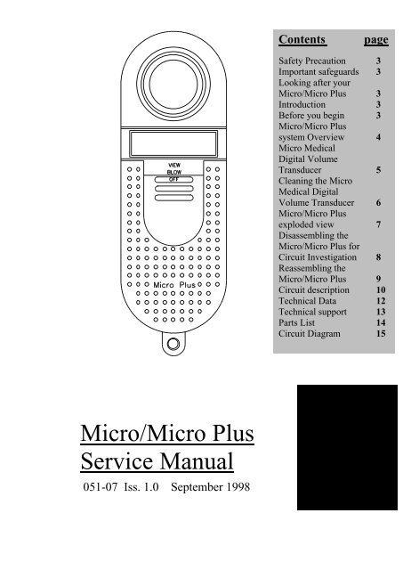
Safety PrecautionThe servicing of this device is intended to be carried out by a properlytrained and competent electronics engineer, or experienced in themaintenance and servicing of medical devices. Read this manualthoroughly before proceeding with the service. If in any doubt pleasecontact the service centre at <strong>Micro</strong> Medical Limited or their accreditedagent in your country or region.Important Safeguardso Read all of the instructions.o Keep the instructions in a safe place for later use.o Follow all warnings and instructions marked on the product.o When replacement parts are required, be sure to use replacement partsspecified by <strong>Micro</strong> Medical that have the same characteristics as theoriginal parts. Unauthorised substitutions may result in fire, electric orother hazards.o Do not place on an unstable table.o The product should be operated only from the type of power sourceindicated on the label.Looking after your <strong>Micro</strong>/<strong>Micro</strong> <strong>Plus</strong> Spirometero Avoid exposing the <strong>Micro</strong>/<strong>Micro</strong> <strong>Plus</strong> Spirometer to direct sunlight.o Avoid operating the spirometer in dusty conditions or near to heatingappliances or radiators.o Do not keep the spirometer in a damp place or expose it to extremetemperatures.o Do not direct the transducer holder towards a strong light source whilstoperating the spirometer.IntroductionThis service manual provides you with information to carry out theservicing operation of the <strong>Micro</strong>/<strong>Micro</strong> <strong>Plus</strong> Spirometer. should the unitbecome faulty It is a process, which is relatively straightforward but mustbe carried out in a logical sequence. Our advice is to familiarise yourselfwith the contents of this manual before attempting to carry out theprocedure of replacing the parts supplied in the service kit for the<strong>Micro</strong>/<strong>Micro</strong> <strong>Plus</strong> Spirometer.Before You BeginBefore you begin the servicing operation, please read the section onCircuit description very carefully:3
<strong>Micro</strong>/<strong>Micro</strong> <strong>Plus</strong> system overview.The <strong>Micro</strong> Medical <strong>Micro</strong>/<strong>Micro</strong> <strong>Plus</strong> Spirometer consists of a hand heldmicrocomputer unit (2) incorporating a <strong>Micro</strong> Medical digital volumetransducer (1).<strong>Micro</strong>Medical1. <strong>Micro</strong> Medical Digital Volume Transducer.2. <strong>Micro</strong> microcomputer unit.3. Lung Function Calculator.4. PP3 Alkaline battery (BAT2).4
<strong>Micro</strong> Medical Digital Volume TransducerThe <strong>Micro</strong> Medical digital volume transducer consists of an acrylic tubewith a vane (3) positioned between a stator (1) and a cross bar (2). The lowinertia vane is attached to a stainless steel pivot (5) which is free to rotate ontwo jewelled bearings (4) mounted at the centre of the stator plate and crossbar. As air is passed through the transducer a vortex is created by the stator,which causes the vane to rotate. The number of rotations is proportional tothe volume of air passed through the transducer and the frequency of rotationis proportional to the flow rate. The transducer passes through the PCB,which contains a light emitting diode (LED) and phototransistor. The LEDproduces an infrared beam, which is interrupted by the vane twice perrevolution. This interruption is sensed by the phototransistor giving a squarewave output on the collector.There is no routine maintenance required for the transducer other thancleaning.1INFRA REDEMITTER25434INFRA REDDETECTORVolume = k X No. ofpulsesVOLUME PROPORTIONAL TO THE NUMBER OF PULSESFLOW PROPORTIONAL TO THE PULSE FREQUENCYFlowk/pulse =period5
Cleaning the Digital Volume TransducerThe transducer requires no routine maintenance or servicing. However if youwish to sterilise or clean the transducer it may be removed by the followingprocedure.1. Remove the transducer by gently pulling from the main body with atwisting action.2. The transducer may now be immersed in warm soapy water for routinecleaning or immersed in a cold sterilising solution e.g. Alkacide for a periodnot exceeding 15 minutes. (Alcohol and chloride solutions should beavoided.)3. After cleaning or sterilising, the transducer should be rinsed in distilledwater and dried.4. Reassemble the transducer into the <strong>Micro</strong>/<strong>Micro</strong> <strong>Plus</strong> Spirometer.Alkacide is available from <strong>Micro</strong> Medical in convenient 250ml plasticbottles (Cat No. SSC1000)6
<strong>Micro</strong>/<strong>Micro</strong> <strong>Plus</strong> Spirometer exploded view (fig 1)Item 8Item 5Item 4Item 6Item 7Item 1Item 3Item 2Item 81. Bottom Moulding 2. Top Moulding3. PCB Assembly 4. Turbine sleeve5. Coated O ring 6. O ring capture ring7. Polycarbonate window 8. 2 x Screws7
Disassembling the <strong>Micro</strong>/<strong>Micro</strong> <strong>Plus</strong> for Circuit Investigation.If the <strong>Micro</strong>/<strong>Micro</strong> <strong>Plus</strong> Spirometer becomes faulty then the followingprocedure is needed to investigate the fault.1 Remove the digital volume transducer from the microcomputer unit bygently pulling the transducer from the microcomputer unit with a twistingaction.2 Turn the unit face down and slide back the battery cover.3 Remove the battery and place to one side.4 Remove the 2 screws on the bottom moulding.5 Turn the <strong>Micro</strong>/<strong>Micro</strong> <strong>Plus</strong> face up and ease the top moulding from thebottom and turn the top moulding over so as the unit is in two halves.6 Remove the PCB from the bottom moulding and put the bottommoulding to one side.7 The <strong>Micro</strong>/<strong>Micro</strong> <strong>Plus</strong> is now ready for fault finding8
Reassembling the <strong>Micro</strong>/<strong>Micro</strong> <strong>Plus</strong>1. Place the PCB into the bottom moulding and wire battery lead as asshown in fig 2.2. Replace items 4, 5 and 6 (Fig1) into the bottom moulding.3. Position top moulding on top of bottom moulding and push together(ensure that the battery leads are not trapped).4. Turn unit face down and replace the 2 screws.5. Replace the PP3 battery ensuring correct polarity.6. Replace the battery cover.7. Turn the unit face up and refit transducer into the microcomputer unit.8. The unit is now ready for operation.Fig 29
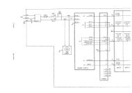
Circuit descriptionThe circuit is based on the Motorola one time programmable (OTP)microcontroller MC68HC705C9ACFN (IC1) operating at a clock frequencyof 1 MHz. This processor contains 7 Kbytes of EPROM, 176 Bytes ofRAM, programmable output latches, and a serial peripheral interface (SPI).The processor monitors pulses from the transducer, calculates thespirometry measurements, and directly drives the LCD display accordingto the position of the slide switch. The state of the battery is alsomonitored and a warning is displayed when necessary. Calibrationinformation is stored in a 256 bit serial EEPROM, IC5, and communicateswith the microcontroller via the SPI.ResetThe reset circuit consists of a single chip reset (IC7) which holds the resetline low for 350ms after the 5 volt supply has reached the thresholdvoltage of 4.5 volts. The reset signal is then applied to the microprocessor(IC1),Power SupplyThe unit is powered an alkaline 9 volt PP3 battery (BAT1) and switched byIC3 which is arranged in a bi-stable configuration. When the unit is turnedon via the slide switch a momentary pulse appears on pin 1 of IC3 by theaction of R8, R9 and C10. This pulse toggles the bi-stable circuit so thatpin 11 of IC3 will go low turning transistor TR4 on and supplying 9 volts tothe low drop out regulator (IC4). When the unit is turned off pin 13 of IC3is pulled low reversing the bi-stable action and turning TR4 off. If the unitis left on without use for 6 minutes then pin 31 of IC1 is driven high undersoftware control turning on TR5 which will turn the unit off via the bi-stablecircuit.Battery monitoringThe terminal voltage of the battery is monitored by the action of R4, R5,R6, and TR2. The emitter of TR2 is held at 5 volts and the base voltage isderived from the battery through the potential divider formed by R4 andR5. When the battery voltage falls to approximately 6 volts, the voltage onthe base of TR2 is 4.4 volts and the transistor turns on. The collector willrise to about 4.6 volts and this is monitored by the processor on pin 13(PB0) when the unit is switched on. When a low battery condition isdetected the processor signals to the user that the battery is low byflashing the letters bat three times on the display accompanied by anaudible warning.10
DisplayThe display is a custom 3½ digit low power LCD. The seven segments ofthree digits are driven directly by ports A, B and C of the microcontrollerwith port PA0 driving the back plane. The decimal point, “1” digit, and theother legends are driven by the 8 bit shift register, IC2, which is controlledby the microcontroller via the SPI interface. The back plane is driven by asquare wave of nominally 60 Hz. The individual segments are driven by asimilar square wave, which is in phase with the backplane when thesegment is off and 180 degrees out of phase when the segment is on.Serial Interface (<strong>Micro</strong> <strong>Plus</strong> unit only)Serial communications are established from the microprocessor to theexternal RS232 port using its serial communications interface (IC6)Transducer interfaceThe rotation of the vane inside the transducer is sensed by the interruptionof an infrared beam produced by the LED and sensed by thephototransistor. The LED is controlled by the emitter follower (TR1) and isonly energised during a spirometry test when the BLOW legend on thedisplay is showing.The light beam is detected by the phototransistor, which is in commonemitter configuration. The load resistor is factory adjusted using VR1 togive the largest collector swing when the turbine is subjected to a flow orair at 37 degrees Celsius saturated with water vapour. VR1 is factory setand should not be adjusted by the user. The signal at the collector isconditioned by the action of the schmitt inverter (IC3) and applied to thepulse capture input of the microcontroller (Pin 42 of IC1). Themicrocontroller calculates the expired volume and flow from the numberand rate of received pulses.CalibrationThe sensitivity of the <strong>Micro</strong> Medical digital volume transducer dependsonly upon the fixed geometry of the stator and is inherently stable. Thecalibration will be unaffected by any dirt which may build up on the statordue to poor cleaning procedures. However, physical damage to statormay adversely affect calibration and in this instance the unit should bereturned to <strong>Micro</strong> Medical for transducer replacement and re-calibration.At <strong>Micro</strong> Medical calibration is performed with a computer controlledwaveform generator, approved by the American Thoracic Society.11
Technical DataTransducer Type<strong>Micro</strong> Medical Uni-Directional Digital VolumeResolution10mlAccuracy+/-3%.(To ATS recommendations Standardisation of Spirometry 1994update for flows and volumes).Volume Range0.1-9.99 litres B.T.P.SFlow Range30L/min-1000L/minDisplayCustom 3½ digit Liquid crystalPower Supply9V PP3 dry cellDimensions170 x 60 x 70mm (including transducer)WeightUnit only: 150gUnit and accessories: 550gOperating temperature0 to +40°COperating Humidity30% to 90% RHStorage Temperature-20 to +70°CStorage Humidity10% to 90% RH12
Technical SupportGreat Britain and World Headquarters<strong>Micro</strong> Medical LtdPO Box 6RochesterKent ME1 2AZTelephone + 44 (0)1634 360044Fax +44 (0)1634 360055Web SiteEmailhttp://www.micromedical.com.uksupport@micromedical.com.ukContact <strong>Micro</strong> Medical Ltd for the local agent in your region orcountry for local service:13
Parts ListDesignationDescriptionIC1 (MC68HC705C9ACFN) MOTOROLA SURFACE MOUNT OTP MICROCONTROLLERIC2 (74HC164) 8 BIT SURFACE MOUNT SERIAL TO PARALLEL SHIFT REGISTERIC3 (4093) SURFACE MOUNT QUAD SCHMITT NAND GATEIC4 (LM2931M-5.0) LOW DROP OUT LOW POWER SURFACE MOUNT 5 VOLT REGULATORIC5 (93C06) 256 BIT SERIAL SURFACE MOUNT EEPROMIC6 (MAX3221CAE) SURFACE MOUNT RS232 TRANSCEIVER (MICRO PLUS ONLY)IC7 (DS1233D-10) DALLAS ECONO RESETTR1 (DTB113EK) RHOM PNP DIGITAL TRANSISTORTR2 (FMMT591) ZETEX PNP TRANSISTORTR3 (SDP8405) HONEYWELL PHOTOTRANSISTORTR4 (FMMT591) ZETEX PNP TRANSISTORTR5 (DTC114EK) RHOM NPN DIGITAL TRANSISTORLED (SEP8705) HONEYWELL INFRA RED LEDD1 (BAT42) GENERAL PURPOSE SCHOTTKY DIODEDISPLAY 3½ DIGIT CUSTOM DISPLAYR1 2.2M SURFACE MOUNT RESISTOR 0.1 WATT 5% SIZE 0805R2 120 OHM ¼ WATT 5% RESISTORR3 1K SURFACE MOUNT RESISTOR 0.1 WATT 5% SIZE 0805R4 33K SURFACE MOUNT RESISTOR 0.1 WATT 5% SIZE 0805R5 100K SURFACE MOUNT RESISTOR 0.1 WATT 5% SIZE 0805R6 100K SURFACE MOUNT RESISTOR 0.1 WATT 5% SIZE 0805R7 100K SURFACE MOUNT RESISTOR 0.1 WATT 5% SIZE 0805R8 1M SURFACE MOUNT RESISTOR 0.1 WATT 5% SIZE 0805R9 1M SURFACE MOUNT RESISTOR 0.1 WATT 5% SIZE 0805R10 100K SURFACE MOUNT RESISTOR 0.1 WATT 5% SIZE 0805R11 10K SURFACE MOUNT RESISTOR 0.1 WATT 5% SIZE 0805R12 100K SURFACE MOUNT RESISTOR 0.1 WATT 5% SIZE 0805R13 10K SURFACE MOUNT RESISTOR 0.1 WATT 5% SIZE 0805VR1 20K SINGLE TURN POTENTIOMETERC1 (16MH547M6357) RUBYCON 47µF 16 VOLT ELECTROLYTIC CAPACITORC2 (16MH547M6357) RUBYCON 47µF 16 VOLT ELECTROLYTIC CAPACITORC3 47pF CERAMIC CAPACITOR SIZE 1206C4 47pF CERAMIC CAPACITOR SIZE 1206C5 0.33µF SURFACE MOUNT MULTILAYER CERAMIC SIZE 0805 (MICRO PLUS ONLY)C6 47nF SURFACE MOUNT MULTILAYER CERAMIC SIZE 0805 (MICRO PLUS ONLY)C7 0.33µF SURFACE MOUNT MULTILAYER CERAMIC SIZE 0805 (MICRO PLUS ONLY)C8 0.33µF SURFACE MOUNT MULTILAYER CERAMIC SIZE 0805 (MICRO PLUS ONLY)C9 0.1µF SURFACE MOUNT MULTILAYER CERAMIC SIZE 0805C10 0.1µF SURFACE MOUNT MULTILAYER CERAMIC SIZE 0805SK1 (JY-3530) 3.5mm STEREO JACK SOCKET (MICRO PLUS ONLY)PL1 4 WAY 0.1” PITCH PIN HEADER (MICRO ONLY)SW1 (SLF2300) DOUBLE POLE 3 POSITION SLIDE SWITCHSPKR (PKM35-4A0) MURATA PIEZO CERAMIC SOUNDERBAT1 DURACELL PROCELL PP3 9V BATTERYX1 4MHZ CERAMIC RESONATORTP1 1mm PRESS FIT TERMINAL POSTTP2 1mm PRESS FIT TERMINAL POST14