
Create successful ePaper yourself
Turn your PDF publications into a flip-book with our unique Google optimized e-Paper software.
<strong>Bevel</strong>-<strong>Up</strong><strong>Jack</strong> <strong>Rabbet</strong> <strong>Plane</strong>U.S. Pat. Nos. 7,603,783 & 7,117,602
The Veritas ® <strong>Bevel</strong>-<strong>Up</strong> <strong>Jack</strong> <strong>Rabbet</strong> <strong>Plane</strong> is predominantly used for large-scalerabbets, as well as raised panel work – anywhere you need to make a long, widecut that would require major effort with a smaller rabbet or shoulder plane. Thebevel-up configuration makes it easy to modify the cutting characteristics of theplane by simply adjusting the blade bevel angle.The blade is bedded at 15°, which results in an effective cutting angle of 40°with the supplied 25° lapped blade. Blades are available in A2 tool steelhardened to Rc60-62, O1 tool steel hardened to Rc58-60, as well as inPM-V11 TM , our proprietary high-performance powdered metal alloy. Hardened toRc60-63, our PM-V11 blades offer superior edge retention, even at bevel anglesbelow 25°, while still being sharpenable with conventional abrasives.The plane features an adjustable mouth that can be closed to a narrow slit forfine shavings with minimum tear-out or opened for heavier cuts. All of this canbe done quickly and accurately with the toe locking knob and the unique mouthadjustment screw.Made of fully stress-relieved, ductile cast iron, the plane is accuratelymachined and ground so that the sole is flat and the sides are square tothe sole.The large wooden front knob and rear handle provide a comfortable grip. The reartote can be tilted and locked to either side for knuckle clearance when planingdeep rabbets.With its combined feed and lateral adjustment knob, the Norris-style adjustmentmechanism makes blade setting easy and accurate. The blade is held in alignmentusing four set screws, allowing the blade edge to be precisely aligned with theside of the plane.Mounted on two steel fence rods with brass collet screws, the 7 3 /8" long removablefence can be set up to 5 1 /4" from the shoulder and is through-drilled to accept auser-made wooden sub-fence extension. The fence can be mounted on either sideof the plane body to effectively make right- or left-handed corner cuts cleanlyand accurately.Two independent scoring blades sit ahead of the blade. These are used to reducetear-out on cross-grain work, but can be withdrawn for work with the grain.2
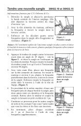
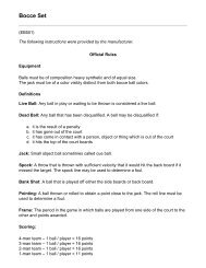
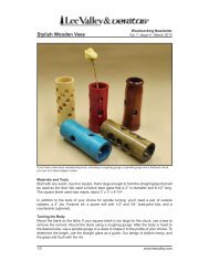
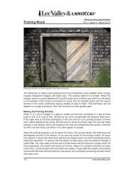
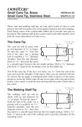
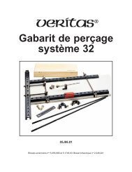
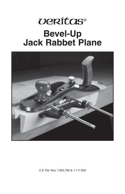
Lever Cap KnobToteLever CapBodyBladeMouth Adjustment ScrewToe Locking KnobAdjustment MechanismSet ScrewsFence Locking KnobFence RodsUser-MadeSub-FenceFenceScoring BladeFigure 1: Veritas ® <strong>Bevel</strong>-<strong>Up</strong> <strong>Jack</strong> <strong>Rabbet</strong> <strong>Plane</strong>.Installing the BladeCaution: Be aware that the blade is sharp; careless handling can result inserious injury.At first glance, the blade seems impossible to install. The key is to fully open thetoe so that the blade can be installed through the mouth opening.Adjuster HoleToe as farforward aspossible.Blade inserted upthrough mouth.Adjuster PinFigure 2: Installing the blade.Position the blade on the blade bed such that the adjuster pin is in the firstadjuster hole.Install the lever cap and lightly tighten the lever cap knob.3
Setting the Blade for Planing without the FenceTo initially set the blade, open the mouth fully, and place the plane on a flat woodsurface (e.g., a scrap of stock). Lightly clamp the blade with the lever cap knoband advance the blade until it just touches the wood.Flip the plane to a sole-up position, then sight along the sole to ensure the bladeedge is parallel to the sole and advance or retract it as required. Clamp fully (aquarter turn should be ample – do not overclamp) and take a test cut. If all is well,advance the set screws on either side of the body until they just touch the blade,not to clamp it but to create a guide so that you do not have to be concerned aboutthe blade shifting. You will quickly get accustomed to setting blade depth only bysighting along the sole, but for setting very fine shavings, you will still need totake test cuts.Setting the Blade for Planing with the FenceWhen cutting rabbets, the position of the blade relative to the plane body iscritical for optimum performance. The cutting edge must be set to the correctprojection to achieve the desired depth of cut and must be parallel to the soleof the plane. In addition, to ensure that it cuts right into the corner of a rabbet,it is critical that the inside edge of the blade extend just beyond the side ofthe plane.Note: The slight gap between the blade and the outer edge of the bed is due to designand manufacturing requirements; it does not affect the plane’s performance.The proper blade position relative to the side of the plane is established usingthe four blade set screws. First, back off the lever cap knob just enough to freeup the blade. Then, while holding the blade against the two outer set screwswith your finger, adjust the two set screws until the correct blade position isattained. Remember to keep the cutting edge parallel with the sole. When all iswell, adjust the outer set screws until they just contact the blade; again, not toclamp it, but to create a guide. Once set, the set screws will allow the blade tobe adjusted for depth of cut, as well as allow it to be removed from the planeand then returned to its previously established position.The blade adjustment mechanism is retained in the body by a small setscrew in the back of the housing. If you need to remove the mechanism,back this set screw off until the mechanism can be removed. (It is notnecessary to completely remove the set screw.) When reinstalling themechanism, tighten the set screw only such that the mechanism cannotbe removed.4
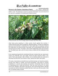
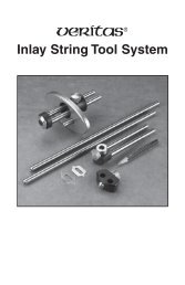
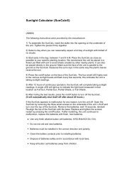
Two Cautionary Notes1. The lever cap clamping knob has tremendous mechanical advantage.For normal use, it needs to be tightened only a quarter turn after fullengagement with the blade. Never torque it down as hard as you canor you may damage the plane.2. Before advancing the blade at any time, check the mouth opening tobe sure you don’t run the blade against the adjustable toe piece. It is asimple matter to close the mouth to the desired opening after you havereached the right blade projection.Backlash and How to Avoid ItTo eliminate the possibility of the blade shifting backward unpredictablyas the backlash is taken up, the final setting should always be made withthe blade being advanced by the clockwise movement of the thumbscrew.If you need to retract the blade slightly, retract it more than required, andfinish by advancing it to its desired position. This takes up all the playin the forward direction, resisting the backward forces experienced bythe blade.Auxiliary FenceA jack rabbet plane is primarily used for large rabbets, so it is advisable to add alarger auxiliary fence to better register the plane to the workpiece. Simply makea wooden fence, as plain or fancy as you wish, and attach it using wood screwsthrough the holes in the existing fence. Be sure to use screws that are not so longthat they break through the working face of the wooden fence.Setting the FenceThe width of the rabbet isdetermined by the fencesetting. Loosen the fencelocking knob and slide thefence until the distancefrom the face of the fenceto the outside edge ofthe blade is equal to therequired rabbet width.Retighten the fenceknob. Maximum widthof 2 1 /4" when using theentire blade.Blade cornerjust proudof side.Cuttingedge parallelto sole.<strong>Rabbet</strong>WidthUser-MadeSub-FenceFigure 3: Setting the blade and fence.Fence Knob5
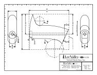
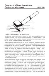
Setting the Scoring BladesThe scoring blades (or nickers) are used when working across the grain. Thecircular blade is attached off-center to an axle, allowing the cutting depth to beadjusted by rotating the blade and axle. (It can also be shifted to a neutral positionwhen it is not required. Generally, only one scoring blade would be used at a time,depending on which side of the plane the rabbet was being cut.) To rotate the axle,you must first release the locking screw that holds it in position. Once the scoringblade is in the desired position, retighten the locking screw.The outside (or cutting) edge of the scoringblade must extend just beyond the side ofthe plane and be aligned with the cornerof the blade. To adjust the scoring bladerelative to the side of the plane, loosenthe scoring axle locking screw. Adjust thecutter position with the depth adjust setscrew. While pressing the scoring bladeand axle in against the set screw, turn theset screw clockwise or counterclockwiseas required, until the scoring blade ispositioned just proud of the side of theplane. Once the position of the scoringblade is established, retighten thelocking screw.Depth AdjustSet ScrewLockingSet ScrewScoringAxleFigure 4: Setting the scoring blade.Mouth AdjustmentThe movable toe piece enables you to set the gap between the blade andthe toe piece (this opening is called the mouth) to suit the task. Generally,you will want a mouth as small as will allow the shaving to escape.The reason for this is that a tight mouth supports the wood ahead of theblade, preventing break-out, a shaving propagating below the surface ofthe workpiece.The mouth adjustment screw allows you to accurately set this opening and,once set, ensures that you cannot inadvertently slide the toe backwards so thatit contacts, and possibly damages, the blade. Loosen the toe locking knob and,holding the plane vertically, nose up, adjust the position of the toe by turning themouth adjustment screw in or out as required. When the desired mouth opening isachieved, tighten the toe locking knob firmly, but avoid overtightening.ToeLockingKnobMouthAdjustmentScrewToeFigure 5: Mouth adjustment.Mouth6
Tote AdjustmentThe bevel-up jack rabbet plane has a tilting rear tote to provide clearance whencutting deep rabbets or working against a batten. To adjust the handle, loosen thehandle locking screw until the handle is free to rotate on the mounting boss. Tiltthe handle to the desired side so it engages in the required slot in the boss. Tightenthe handle locking screw.HandleHandle LockingScrewFigure 6: Tote adjustment.Blade SharpeningMounting BossThe 25° bevel blade will be a good starting bevel for softwood and some hardwoods.Ring-porous hardwoods such as oak may require a 30° bevel to prevent bladeedge failure. Simply hone the micro-bevel to the required angle.It is difficult to be definitive about bevel angles. If you are always working clearpine, you can get away with lower bevel angles. Only you know which wood youwill be working and how you will be working it. Experience will tell you whatyou can and cannot do.7
Care and MaintenanceThe body of the bevel-up jack rabbet plane is ductile cast iron and comes treatedwith rust preventative. Remove this using a rag dampened with mineral spirits.Clean all machined surfaces, including the area under the nose and the toe itself.We recommend that you initially, then periodically, apply a light coat of siliconefreepaste wax to seal out moisture and prevent rusting; this also has the addedbonus of acting as a lubricant for smoother planing. Wipe off any wood dust fromthe surfaces that you will be waxing, apply a light wax coating, let dry, then buffwith a clean soft cloth. At the same time, the solvents in the wax will remove anyharmful oils left from your fingers that can lead to corrosion.Before treating a plane with a sealant, wipe off any fingerprints with a clothdampened with a small amount of light machine oil. Remove any residual oil;then apply the sealant to the plane’s sole and cheeks.If storage conditions are damp or humid, the plane should, in addition to thetreatment outlined above, be wrapped in a cloth or stored in a plane sack. Thisprecaution will also guard against dings and scratches.Every so often, take the plane apart to clean and lubricate it where necessary.Remove the lever cap, blade, adjustment mechanism and toe from the body. Cleanall parts with a cloth dampened with a dab of light machine oil. The blade bed andmachined contact surfaces between the body and toe, as well as the adjustmentcomponents (pivot, threaded shaft and traveller), will benefit from a light coat ofoil to keep them working freely. For corroded plane bodies, we recommend youfirst remove the rust with a fine rust eraser, then treat as described above.The bright finish on the brass components can be maintained as above. If a patinafinish is preferred, simply leave the brass components unprotected until the desiredlevel of oxidation has occurred, then apply a sealant. If you want to make thembright and shiny again, you can revitalize the surface with a brass polish.The rosewood knob and handle have a lacquer finish and should require nothingmore than a wipe with a clean cloth from time to time.Accessories05P53.02 A2 Blade05P53.52 O1 Blade05P53.72 PM-V11 TM Blade814 Proctor AvenueOgdensburg NY 13669-2205United States1090 Morrison DriveOttawa ON K2H 1C2Canadacustomerservice@veritastools.com© Veritas <strong>Tools</strong> Inc. 2012 www.veritastools.com 768 IWE-585 Rev. A