Pinnacle RV Digital Satellite System Models RD-9946 ... - Winegard
Pinnacle RV Digital Satellite System Models RD-9946 ... - Winegard
Pinnacle RV Digital Satellite System Models RD-9946 ... - Winegard
- No tags were found...

You also want an ePaper? Increase the reach of your titles
YUMPU automatically turns print PDFs into web optimized ePapers that Google loves.
Table Of ContentsInstallation Requirements ....................................................................................................................................... 4Installation ............................................................................................................................................................... 6<strong>RD</strong>-9901 Remote Wall Plate Control Installation (optional) ................................................................................. 14<strong>RD</strong>-9911 Warning Device Installation (optional) .................................................................................................. 15Cable Roof-thru Plate Installation ......................................................................................................................... 16Unpacking/InventoryAfter unpacking system verify that no parts have broken, bent etc., and that youhave the following items:1 Positioner ............................................ 27502251 Ignition Wire Harness .......................... 27532541 Antenna Support Assembly................. 27628301 Mount Assembly .................................. 27628321 Mount Base Assembly ........................ 27628311 Antenna/Feed Assembly ..................... 27628331 35' Wire Harness ................................. 27532484 10-31 Washer ...................................... 21603494 10-32 x 1-1/8" Hex Head Screw .......... 21601704 Black Cable Ties ................................. 21901051 13 Pin Connector................................. 23401491 FS-8100 Male to Male F-connector .... 23600601 18" RG-6 Coax Cable w/connectors ... 27530591 3 oz. Silicone Sealant.......................... 24600071 Dual cable roof-thru plate .................... 320015910 #10 x 1" Screw .................................... 2160178FCC PART 15 STATEMENTSNOTE: This equipment has been tested and found to comply with the limits for a Class B digital device, pursuant toPart 15 of the FCC Rules. These limits are designed to provide reasonable protection against harmful interferencein a residential installation. This equipment generates, uses and can radiate radio frequency energy and, if notinstalled and used in accordance with the instructions, may cause harmful interference to radio communication.However, there is no guarantee that interference will not occur in a particular installation. If this equipment does causeharmful interference to radio or television reception, which can be determined by turning the equipment off and on,the user is encouraged to try to correct the interference by one or more of the following measures:• Reorient or relocate the receiving antenna.• Increase the separation between the equipment and receiver.• Connect the equipment to an outlet on a circuit different from that to which the receiver is connected.• Consult the dealer or an experienced radio/TV technician for help.CAUTION: Any changes or modifications to this equipment not expressly approved by <strong>Winegard</strong> Companymay void the user’s authority to operate this equipment.3Rev 5/99
Figure 4 Rev 9/985
Seal connections from pointto point indicatedFigure 7Mount AssemblyUse FS-8100 connector toconnect coax cables5. Set mount assy. onto the mount base, making sure to coil cables undermount base. Make cables do not make contact with the azmuth limit switcheson the bottom of the mount assembly, Figure 9. Rotate mount assembly.counterclockwise to lock mount onto mount base. Secure mount assy. tomount base using screws provided. See Figure 8.(2) 10-32 x 5/8"Hex HeadScrew(2) 10-32WasherSet mount assy. onto themount base and rotate sothat it locks into place.Secure mount assy. tomount base with screwsprovided.Point to front ofvehicleDO NOT CAULKMOUNT BASERINGCaulk all mounting holesand cable entry.Coil cables under mountbase. Make sure cables donot make contact with thelimit switches on the bottomof the mount assenbly.Mount BaseAntenna Support mountingAntenna Supporthole(s) 1/4" dia.Figure 8 Rev 9/987
Azmuth SpringAzmuth Limit SwitchesDuring installation make surethese cables DO NOT come intocontact with the azmuth spring oflimit switches.Figure 98
6. Attach coax cable from antenna assy. to jack on mount, see Figure 10.Make sure to feed coax cable under the shaft. Slide weather boot over bootcollar.7. Attach antenna/feed assembly to mount with (2) 10-32 x 1-1/8" screws andwashers provided, see Figure 10. (Torque: 6 ft. lbs.)Antenna/FeedAssembly(2) 10-32 x 1/1/8"Hex Head Screw(2) 10-32 WashersMount AssemblyFigure 10Feed coax under shaft.Rev. 5/999
8. After feeding cable to where you are going to install the positioner, strip3/8" insulation off all wires in the 13 cable bundle.9. Attach wires as shown in Figure 11 to the 13 pin connector supplied.Double check that wires will not pull out and that wire colors are correct.NOTE: The first color is the primary color of the wire. Example; Red/White, means that the wire is red with a white stripe.13 Pin ConnectorScrews used tosecure connectorto positioner.Green/BlackRed/BlackRed/WhiteGreenRedBlackBlueWhiteBlack/WhiteOrange/BlackWhite/BlackBlue/BlackOrangeFigure 1110. You are now ready to connect the mount to the positioner and thepositioner to the receiver, see Figures 12 and 13. Make sure there is adequateventilation. The positioner and the receiver produce heat.NOTE: When connecting the 13 pin connector to the rear of positionermake sure to secure connector to positioner using the screws on theconnector.CAUTIONDO NOT CONNECT EITHER THE POSITIONER OR RECEIVER TO ACPOWER UNTIL ALL CONNECTIONS HAVE BEEN MADE. BOTH UNITSARE ON AS SOON AS THEY ARE CONNECTED TO POWER.Rev. 6/9810
TORECEIVER13 BLUE/BLACKTOANTENNA3 RED/WHITE4 GREEN5 RED6 BLACK7 ORANGE8 BLUE9 WHITE10 BLACK/WHITE11 ORANGE/BLACK12 WHITE/BLACK2 RED/BLACK1 GREEN/BLACKWINEGA<strong>RD</strong>P/N:2750225120 VAC 60 Hz100 WATTS MAXREMOTECONTROLPANEL46 CM 60CMMake sure switch is inthe 46CM position.Switch removed 2/23/98.After all otherconnections are madeconnect AC powercord to 120 VAC outlet.SILVERConnect to vehicle ground.GOLDConnect to ignition +12 VDC.This connection is optional. If usedantenna will be put into travel positionwhenever the ignition is turned ON andthere is AC power to the positioner.IGNFigure 12Connect 13 pin connectorhere, makeing sure wirecolors match. Secureconnector to positionerwith screws molded intoconnector.Optional <strong>RD</strong>-9901 RemoteControl Wall Plate. Connectedby 25' telephone-type wire withmodular plug-in connections.Connect 75 ohm coaxialcable to SATELLITE INjack on receiver.Connect 75 ohm coaxialcable from antenna.Rev. 6/98WARNINGINDICATOROptional <strong>RD</strong>-9911 WarningDevice Refer to Figure 15,Page 14 for operation andinstallation.11
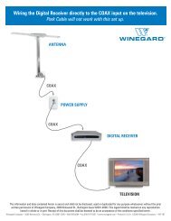
SENSAR ® TVANTENNARECEIVERAntenna In<strong>Satellite</strong> InCH 3/4 OUTPOSITIONERTo ReceiverControl WiresTo AntennaTV SETVCRFigure 13Rev. 6/9812
NOTE: All commands will be shown in bold with brackets, example[SELECT A].11. Plug positioner into AC receptacle.12. Press [UP/DOWN] arrow until you get Park displayed on positionerdisplay. See Figure 14.2. Press SELECT A or B asappropriate1. Press UP/DOWN arrowbuttons to get Park onscreenSELECT ASELECT BParkMove to Last SatPINNACLEPOSITIONERby WINEGA<strong>RD</strong>Model <strong>RD</strong>-9900Figure 1413. Press [SELECT A or B] Park to put antenna into park (travel) position. SeeFigure 14. The positioner will display Collapsing <strong>System</strong> while antenna ismoving to travel position.14. Verify that antenna is in the travel position (see Figures 2 and 3) whenCollapsing <strong>System</strong> is replaced with normal menu, Figure 15.SELECT ASELECT BSearchParkDSSPINNACLEPOSITIONERby WINEGA<strong>RD</strong>Model <strong>RD</strong>-9900Figure 15You are now ready to enjoy satellite TV! Refer to Operation Manual onhow to acquire the satellite signal.Rev. 6/9813
<strong>RD</strong>-9901 Remote Control Wall Plate InstallationTo install the optional <strong>RD</strong>-9901, proceed as follows:1. Connect the 25' telephone cord to the REMOTE CONTROL PANEL plugon rear of positioner. See Figure 16.NOTE: The <strong>RD</strong>-9901 will fit into a standard electrical outlet box.2. Connect other end of telephone cord to plug on side of <strong>RD</strong>-9901. SeeFigure 16.3. Secure <strong>RD</strong>-9901 with screws provided.NOTE: Refer to Operation Manual on how to operate the <strong>RD</strong>-9901.Positioner Rear PanelREMOTECONTROLPANEL<strong>RD</strong>-9901 Remote ControlWall Plate25' Telephone CordFigure 16Rev. 6/9814
<strong>RD</strong>-9911 Warning Device Installation/OperationTo install the Warning Device, proceed as follows:1. Connect the gold colored wire of the warning device wire harness to ignition+12 VDC (there is only +12 VDC present when ignition is turned ON) SeeFigure 17.2. Connect the silver colored wire to vehicle ground. See Figure 17.3. Connect other end of wire (end with molded plug) to warning device. SeeFigure 17.4. Insert the two "AA" batteries into the warning device.5. Connect the single RCA cable to the WARNING INDICATOR jack onpositioner (see Figure 11). Connect the other end to the warning device. SeeFigure 17.NOTE: It is recommended that you place the warning device where it willbe visible when you start your vehicle. There is no buzzer, only lights inthe device. Velcro is provided to help in the placement of the device.Operation: A red light indicates that the system is still in the raisedposition and not ready for travel. Red light goes off when in downposition. A yellow light comes on when battery is low. Lights only comeon when +12 VDC is applied to warning device.Positioner Rear PanelWARNINGINDICATORRCA cableInstall two "AA"batteries providedWarning DeviceSILVERConnect to vehicle groundGOLDConnect to ignition +12 VDCFigure 17Rev. 6/9815
Cable Roof-thru Plate InstallationIf your going to use option B for you cable entry in to your <strong>RV</strong>/coach proceedto step 1.1. To install the cable roof-thru plate make sure that you have the following:QTY Description Part # Use1 3 oz. Silicone Sealant 2460007 Used to seal cable entry plates1 Dual cable roof-thru plate 3200159 Seal dual cable entry10 #10 x 1" Screw 2160178 Attach cable entry plate(s) toroof3. Apply silicone sealant under lip of roof-thru plate and where cable entersroof. See Figure 18.4. Attach plate to roof with screws provided. See Figure 18.5. Apply silicone sealant over screws and around edge of roof-thru plate,making sure cable entry is sealed.#10 x 1" ScrewsDual roofthru plateControl cable and coax formount.Make sure cableentry is sealedApply silicone under lip andcable roof holeFigure 18Rev. 6/9816
MUST PERFORM!READ BEFORE PROCEEDING WITH SYSTEMINSTALLATION OR OPERATIONRECEIVER & POSITIONERWhen plugged in, the receiver & positioner are ON. When connecting ordisconnecting any cables to receiver, positioner, or antenna, be sure tounplug from power source.Do not install the receiver and/or positioner where there is no ventilation. Thereceiver/positioner must have adequate ventilation. Excessive heat cancause premature failure of components.WINEGA<strong>RD</strong> SE<strong>RV</strong>ICE DEPARTMENT (800) 788-4417MONDAY THRU FRIDAY, 7:00 - 3:00 PM CENTRAL TIMERev 4/9817
MUST PERFORM!READ BEFORE PROCEEDING WITH POSITIONER REINSTALLATION.After positioner reinstallation, you must put the antenna in the park (travel) position.THIS MUST BE DONE EVEN IF THE ANTENNA IS ALREADY IN THE TRAVELPOSITION. This is done so the positioner will know the antenna position. If not done,damage to the antenna may occur and the system will not operate properly. To parkthe antenna, refer to Operation Manual.WINEGA<strong>RD</strong> SE<strong>RV</strong>ICE DEPARTMENT (800) 788-4417S:\PART-NO\2451171A.PM518
LOCATING THE SATELLITESUGGESTIONS FOR AVOIDINGSATELLITE SIGNAL ACQUISITION ERRORSWith the addition of several new U.S. satellites, your system mayencounter some difficulty locating the correct satellite on the firstattempt.To reduce searching errors, it is recommended that you use the"ENTER ELEVATION" Search method on the <strong>Winegard</strong> AutomaticPositioner. Refer to Pg. 9 in the Operation section of this manual.Elevation can be acquired by entering your local ZIP code in theReceiver Set-up Menu. Once you find the correct elevation, subtract3 degrees and enter this number. Example: If you are in an area thatrequires 41 degrees elevation, enter 38 degrees in the ElevationSearch method.19S:\PART-NO\2451172A 8/99
WINEGA<strong>RD</strong>®<strong>Pinnacle</strong> <strong>RV</strong> <strong>Digital</strong> <strong>Satellite</strong> <strong>System</strong><strong>Models</strong> <strong>RD</strong>-<strong>9946</strong>Operation Manual®U.S. Patent No.5,532,710WARNING!BEFORE ATTACHING OR REMOVING ANY CABLE/WIRES ONBACK OF POSITIONER, UNPLUG UNIT FROM 117 VAC SOURCE.Printed in U.S.A. <strong>Winegard</strong> Company • 3000 Kirkwood St. • Burlington, IA 52601-2000 • 319/754-0600 © 1998 <strong>Winegard</strong> Company 2451172 Rev. 9/9820
IMPORTANT SAFEGUA<strong>RD</strong>SWARNING: THIS SYSTEM HAS BEEN ADJUSTED AT THE FACTORY FOR OPTIMUM PERFORMANCE.BEFORE MAKING ANY ADJUSTMENTS, CONTACT WINEGA<strong>RD</strong> CUSTOMER SE<strong>RV</strong>ICE.WARNING: TO REDUCE RISK OF FIRE OR ELECTRICAL SHOCK,DO NOT EXPOSE TO RAIN OR MOISTURE.(Not applicable to mount and antenna)CAUTIONRISK OF ELECTRIC SHOCKDO NOT OPENDangerous voltageinside enclosureRefer to operating, maintenanceand safeguard literatureaccompanying unit.CAUTION: TO REDUCE RISK OF ELECTRICAL SHOCK,DO NOT REMOVE COVER, NO USER-SE<strong>RV</strong>ICEABLE PARTS INSIDE.REFER SE<strong>RV</strong>ICING TO QUALIFIED PERSONNEL1. All the safety and operating instructions shouldbe read before the appliance is operated.2. The safety and operating instructions should beretained for future reference.3. All warnings on the appliance and in the operatinginstructions should be adhered to.4. All operating and use instructions should befollowed.5. Unplug this video or audio product from the walloutlet before cleaning. Do not use liquid cleanersor aerosol cleaners. Use a damp cloth for cleaning.6. Do not use attachments not recommended bythe video product manufacturer as they may causehazards.7. Do not use this video product near water - forexample, near a bath tub, wash bowl, kitchen sink,or laundry tub, in a wet basement, or near aswimming pool, and the like.8. If slots, holes and openings are located in thehousing, they are provided for ventilation and toensure reliable operation of the video product andto protect it from overheating. These openingsshould never be covered. The openings shouldnever be blocked by placing the video product ona bed, sofa, rug, or other similar surface. Thisvideo product should never be placed near or overa radiator or heat register. This video productshould not be placed in a built-in installation suchas a bookcase or rack unless proper ventilation isprovided or the manufacturer's instructions havebeen adhered to.9. This video product should be operated only fromthe type of power source indicated in electricalrating printed on the appliance or power supply.10A. If the appliance is equipped with a polarizedalternating-current line plug (a plug having oneblade wider than the other) this plug will fit into thepower outlet only one way. This is a safety feature.If you are unable to insert the plug fully into theoutlet, try reversing the plug. If the plug should stillfail to fit, contact an electrician to replace yourobsolete outlet. Do not defeat the safety purposeof the polarized plug.10B. If the appliance is equipped with a 3-wiregrounding-type plug, a plug having a third (grounding)pin, this plug will only fit into a grounding-typepower outlet. This is a safety feature. If you areunable to insert the plug into the outlet, contact anelectrician to replace your obsolete outlet. Do notdefeat the purpose of the grounding-type plug.11. Power-supply cord should be routed so that itis not likely to be walked on or pinched by itemsplaced upon or against it, paying particularattention to cord at plug, convenience receptacleand the point where cord exits from the appliance.12. If an outside antenna or cable system is connectedto this video product, be sure system isgrounded so as to provide some protection againstvoltage surges and built-up static charges. Propermethod is shown below.EXAMPLE OF ANTENNA GROUNDING AS PERNATIONAL ELECTRICAL CODE INSTRUCTIONSGround ClampElectricalServiceEquipmentGround ClampsAntennaLead-in WireAntenna Discharge Unit(NEC Section 810-21)Grounding Conductors(NEC Section 810-21)Power Service GroundingElectrode <strong>System</strong>(NEC Art. 250, Part N)NEC - NATIONAL ELECTRICAL CODE13. An outside antenna system should not belocated in the vicinity of overhead power lines orother electric light or power circuits, or where it canfall into such power lines or circuits. When installingan outside antenna system, extreme careshould be taken to keep from touching such powerlines or circuits as contact with them might be fatal.14. For added protection for this video productduring a lightning storm, or when it is left unattendedand unused for long periods of time, unplugit from the wall outlet and disconnect theantenna or cable system.15. Do not overload wall outlets and extensioncords as this can result in a risk of fire or electricshock.16. Never push objects of any kind into this videoproduct through openings as they may touch dangerousvoltage points or short-out parts that couldresult in a fire or electric shock. Never spill liquid ofany kind on the video product.17. Do not attempt to service this video productyourself as opening or removing covers mayexpose you to dangerous voltage or other hazards.Refer all servicing to qualified service personnel.18. Unplug this video product from the wall outletand refer servicing to qualified service personnelunder the following conditions:a. When the power supply cord or plug is damaged.b. If liquid has been spilled or objects have falleninto the video product.c. If the video product, except for antenna mountedpreamplifiers and downconverters, has been exposedto rain or water.d. If the video product does not operate normallyby following the operating instructions. Adjust onlythose controls, when provided, that are covered bythe operating instructions. An improper adjustmentof other controls may result in damage thatwill often require extensive work by a qualifiedtechnician to restore the video product to its normaloperation.e. If the video product has been dropped or thehousing has been damaged.f. When the video product exhibits a distinct changein performance - this indicates a need for service.19. When replacement parts are required, be surethe service technician has used replacement partsspecified by the manufacturer or have the samecharacteristics as the original part. Improper substitutionsmay result in fire, electric shock or otherhazards.20. Upon completion of any service or repairs tothis video product, ask the service technician toperform safety checks to determine that the videoproduct is in proper operating condition.21. Note to CATV system installer: This reminderis provided to call the CATV system installer'sattention to Art. 820-40 of the NEC that providesguidelines for proper grounding and, in particular,specifies that the cable ground shall be connectedto the grounding system of the building, as close tothe point of cable entry as possible.22. This product should be mounted to a wall orceiling only as recommended by the manufacturer.23. The product should be situated away fromheat sources such as radiators, heat registers,stoves or other products (including amplifiers) thatproduce heat.21
TABLE OF CONTENTSIntroduction ...................................................................................................................................................... 4<strong>System</strong> Operation (Finding the digital satellite system satellite(s) ................................................................. 5Using the City Menu ............................................................................................................................ 5Entering Elevation Angle ..................................................................................................................... 9Entering Latitude & Longitude........................................................................................................... 11Putting Antenna in Park Position ................................................................................................................... 14Move to Last <strong>Satellite</strong> .................................................................................................................................... 15Manual Movement ......................................................................................................................................... 16Edit Menu ....................................................................................................................................................... 18Select Search <strong>Satellite</strong> ...................................................................................................................... 19Add/Edit Search <strong>Satellite</strong> .................................................................................................................. 20Set Motor Positions ........................................................................................................................... 22Test Functions ................................................................................................................................... 22Return to Defaults ............................................................................................................................. 22<strong>System</strong> Information ........................................................................................................................... 22Remote Control Panel Operation .................................................................................................................. 23Search for <strong>Satellite</strong> ............................................................................................................................ 23Parking the Antenna .......................................................................................................................... 24Latitude and Longitude Map .......................................................................................................................... 25Positioner Controls & Indicators ...............................................................................................................26-27Programmed City Locations .......................................................................................................................... 28Specifications................................................................................................................................................. 29Warranty Information ..................................................................................................................................... 29FCC PART 15 STATEMENTSNOTE: This equipment has been tested and found to comply with the limits for a Class B digital device, pursuant to Part 15 of theFCC Rules. These limits are designed to provide reasonable protection against harmful interference in a residential installation.This equipment generates, uses and can radiate radio frequency energy and, if not installed and used in accordance with theinstructions, may cause harmful interference to radio communication. However, there is no guarantee that interference will notoccur in a particular installation. If this equipment does cause harmful interference to radio or television reception, which can bedetermined by turning the equipment off and on, the user is encouraged to try to correct the interference by one or more of thefollowing measures:• Reorient or relocate the receiving antenna.• Increase the separation between the equipment and receiver.• Connect the equipment into an outlet on a circuit different from that to which the receiver is connected.• Consult the dealer or an experienced radio/TV technician for help.CAUTION: Any changes or modifications to this equipment not expressly approved by <strong>Winegard</strong> Company may void theuser’s authority to operate this equipment.22Rev. 6/97
INTRODUCTION / HOW DOES DIGITAL SATELLITE TV WORK?INTRODUCTIONWelcome to a new era in <strong>RV</strong> <strong>Satellite</strong> reception. Acombination of the latest computer and microprocessortechnology makes the <strong>Winegard</strong> <strong>Pinnacle</strong> ® satellitepositioner and your digital satellite system receiver theeasiest to operate. A simple button stroke willautomatically direct the antenna to the satellite.HOW DOES DIGITAL SATELLITESYSTEM TV WORK?<strong>Satellite</strong> programming originates from an “uplink” facility.The DBS satellites receive the uplink signal, amplify itand then transmit it back to earth in the Ku frequencyband.This signal is received by a satellite antenna whoseshape reflects and concentrates the signal to the LNBFattached to the antenna. The LNBF is located at the“focal point” of signal reflection, that is, the point at whichthe maximum amount of signal is effectivelyconcentrated. The LNBF amplifies and converts thesignal to the 950 to 1450 MHz range. The signal is thenpassed thru a coaxial cable to the positioner, then to thereceiver where individual channel selection andprocessing take place.For Programming information call:DISH NETWORK - 1-800-333-3474DSS ®DIRECTV - 1-800-347-3288USSB - 1-800-204-8772DIGITAL BROADCASTSYSTEM SATELLITE(S)HIGH POWER KU-BANDDOWNLINK SIGNALUPLINK SIGNALWINEGA<strong>RD</strong> AUTOMATICDIGITAL SATELLITESYSTEM ANTENNAWINEGA<strong>RD</strong>SENSAR ® ANTENNAPROGRAMMING UPLINKCONTROL CENTERSRECEIVERPOSITIONERTVDSS ® is a registered trademark of DIRECTV Inc. a unit of Hughes Electronics Corporation23
SYSTEM OPERATION (FINDING THE SATELLITE(S)Your new <strong>Winegard</strong> <strong>RV</strong> <strong>Digital</strong> <strong>Satellite</strong> <strong>System</strong> is an easy-to-install, easy-tousesatellite TV reception system. Because it mounts on the top of yourrecreational vehicle, it goes where you go and provides quality reception ofdigital satellite signal in the continental United States only.NOTE: All commands will be shown in bold with brackets, example[SELECT A].One requirement must be met to fully enjoy automatic system TV viewing.The <strong>RV</strong> must be reasonably level. Any of the leveling indicators availableshould be adequate for this purpose. If the <strong>RV</strong> is not leveled, the systemmay not find the high power satellites.After the <strong>RV</strong> has been leveled, proceed as follows:Finding the <strong>Satellite</strong>Method 1:Using the City MenuNOTE: SELECT A choosestop option, SELECT Bchooses bottom option.2. Press SELECT AThere are three ways to find the satellite(s). Using the city menu to find theclosest city, entering the elevation angle for your location or entering thelatitude and longitude for your location. Each is explained in the followingparagraphs.1. Turn TV ON and tune to channel 3 or 4 (output channel of receiver).2. Press [POWER] on receiver remote to turn satellite receiver on.3. On positioner press [UP/DOWN] arrow button until Search DSS appearson the positioner screen, Figure 1. If you want to search for a different satelliterefer to Edit Menu on page 18 to change search satellites.1. Press UP/DOWN arrow buttons to get Search DSS on screenSELECT ASELECT BSearchParkDSSPINNACLEPOSITIONERby WINEGA<strong>RD</strong>Model <strong>RD</strong>-9900Figure 13. Press SELECT A4. Press [SELECT A] to enter the search function, Figure 1. (Press [SELECTB] if Search DSS is bottom option on screen.5. Press [SELECT A] Select a City, Figure 2. There is a list of 125 cities inthe continental Untied States stored in the positioner memory. See ProgrammedCity Locations, page 28.SELECT ASELECT BSelect a CityEnter ElevationPINNACLEPOSITIONERby WINEGA<strong>RD</strong>Model <strong>RD</strong>-990024Figure 2Rev. 6/97
6. Press [UP/DOWN] arrow buttons to scroll cities, Figure 3. The cities arelisted alphabetically by state. Pressing the [RIGHT] arrow button will scroll thelist to the first entry of the next state. Pressing the [LEFT] arrow button willscroll the list to the last entry of the previous state.5. Press SELECT A or Bfor the nearest city4. Press UP/DOWN arrowbuttons to scroll throughCity listPress RIGHT arrow buttonto scroll list to the first entryof the next stateSELECT ASELECT BBURLINGTONSOIUX CITYIAIAPINNACLEPOSITIONERby WINEGA<strong>RD</strong>Model <strong>RD</strong>-9900Figure 3Press LEFT arrow button to scroll list to the lastentry of the previous state7. Press [SELECT A or B] once you have scrolled to the closest city to yourlocation, Figure 3.6. Press SELECT A8. Press [SELECT A] Start Search, Figure 4. This will begin the search forsatellite operation. If you selected the wrong city press [SELECT B] Quit, thiswill return you to step 3. Repeat 3 through 7 to select the correct city.SELECT ASELECT BStart SearchQuitPINNACLEPOSITIONERby WINEGA<strong>RD</strong>Model <strong>RD</strong>-9900Figure 4Positioner is calculating correct elevation angle for antennaNOTE: When the system starts searching for the satellite, the followingmessages will be displayed on the positioner screen. No input isrequired.SELECT ASELECT BCalculating . . .PINNACLEPOSITIONERby WINEGA<strong>RD</strong>Model <strong>RD</strong>-9900Figure 525
Positioner is setting appropriate detector level (amount of signalrequired)SELECT ASELECT BSetting DetectorPINNACLEPOSITIONERby WINEGA<strong>RD</strong>Model <strong>RD</strong>-9900Figure 6Positioner is moving antenna to start positionSELECT ASELECT BMoving to StartPINNACLEPOSITIONERby WINEGA<strong>RD</strong>Model <strong>RD</strong>-9900Figure 7<strong>System</strong> is now searching for satelliteSELECT ASELECT BSearching (350)Level = 238PINNACLEPOSITIONERby WINEGA<strong>RD</strong>Model <strong>RD</strong>-9900Figure 8<strong>System</strong> has found the satellite and is fine tuning antenna positionSELECT ASELECT BFine TuningAzimuthPINNACLEPOSITIONERby WINEGA<strong>RD</strong>Model <strong>RD</strong>-9900Figure 926
<strong>System</strong> has found a satellite and is fine tuning the signalSELECT ASELECT BFine TuningElevationPINNACLEPOSITIONERby WINEGA<strong>RD</strong>Model <strong>RD</strong>-9900Figure 109. Verify that system has found correct satellite (you will see a picture). SinceDBS services use a digital signal and the satellites are only separated by 9 o ,the system can find the wrong satellite. Press [SELECT A] if correct satellitewas found, Figure 11. You are now ready to watch satellite TV! If the wrongsatellite was found, press [SELECT B] to continue the search.If no satellite is found the message <strong>Satellite</strong> Not Found, Press Any Button,will be displayed by the positioner. Press any button to return to the menushown in Figure 1, page 4.7. Press SELECT A if correct satellite was foundSELECT ASELECT BCorrect <strong>Satellite</strong>Continue SearchPINNACLEPOSITIONERby WINEGA<strong>RD</strong>Model <strong>RD</strong>-9900Figure 11Press SELECT B if correct satellite was not foundNOTE: If after two (2) tries you still get "<strong>Satellite</strong> Not Found" check that:1. The antenna has a clear view of the satellite(s), no trees,buildings, etc. blocking the view. The satellite signal will not passthrough solid objects.2. Your receiver is turned ON.3. The positioner is connected to the receiver correctly, refer toInstallation Manual.If after checking the above, you still do not find a satellite refer to theTroubleshooting Manual.Rev. 2/9727
Finding the <strong>Satellite</strong>Method 2:Entering the ElevationOne requirement must be met to fully enjoy automatic system TV viewing.The <strong>RV</strong> must be reasonably level. Any of the leveling indicators availableshould be adequate for this purpose. If the <strong>RV</strong> is not leveled, the systemmay not find the high power satellites.After the <strong>RV</strong> has been leveled, proceed as follows:To find the satellite by entering the elevation angle for your location, proceedas follows:1. Turn TV ON and tune to channel 3 or 4 (output channel of receiver).NOTE: SELECT A choosestop option, SELECT Bchooses bottom option.2. Press [POWER] on receiver remote to turn satellite receiver on. Determinecorrect elevation angle by entering the ZIP code for your location into receiver(refer to receiver manual).3. On the positioner press [UP/DOWN] arrow button until Search DSSappears on the positioner screen, Figure 12.2. Press SELECT A1. Press UP/DOWN arrowbuttons to get Search DSSon screenSELECT ASELECT BSearchParkDSSPINNACLEPOSITIONERby WINEGA<strong>RD</strong>Model <strong>RD</strong>-9900Figure 124. Press [SELECT A] to enter the search function, Figure 12. (Press[SELECT B] if Search DSS is bottom option on screen.5. Press [SELECT B] Enter elevation, Figure 13.3. Press SELECT BSELECT ASELECT BSelect a CityEnter ElevationPINNACLEPOSITIONERby WINEGA<strong>RD</strong>Model <strong>RD</strong>-9900Figure 1328
5. Press [ARROW BUTTONS] to enter correct elevation, Figure 14.5. Press SELECT A4. Press UP arrow button toincrease elevation by 1 oincrements4. Press RIGHT arrowbutton to increase elevationby 5 o incrementsSELECT ASELECT BEl Angle = 45PINNACLEPOSITIONERby WINEGA<strong>RD</strong>Model <strong>RD</strong>-9900Figure 144. Press LEFT arrow button to decreaseelevation by 5 o increments4. Press DOWN arrow button todecrease elevation by 1 o increments6. Press SELECT A6. Press [SELECT A] Start Search, Figure 15. This will begin the search forthe satellite. If you selected the wrong elevation, press [SELECT B] Quit, thiswill return you to step 3. Repeat 3 through 5 to select the correct elevation.SELECT ASELECT BStart SearchQuitPINNACLEPOSITIONERby WINEGA<strong>RD</strong>Model <strong>RD</strong>-9900Figure 15 7. Verify that system has found correct satellite (you will get a picture). Sincethe DBS services use a digital signal and the satellites are only separated by9 o , the system can find the wrong satellite. Press [SELECT A] if correctsatellite was found, Figure 16. You are now ready to watch satellite TV! If thewrong satellite was found, press [SELECT B] to continue the search.7. Press SELECT A if correct satellite was foundIf no satellite was found, the message <strong>Satellite</strong> Not Found, Press AnyButton, will be displayed by the positioner. Press any button to return to themenu shown in Figure 12, page 9.SELECT ASELECT BCorrect <strong>Satellite</strong>Continue SearchPINNACLEPOSITIONERby WINEGA<strong>RD</strong>Model <strong>RD</strong>-9900Figure 16Press SELECT B if correct satellite was not found29
Finding the <strong>Satellite</strong>Method 3:Entering the Latitudeand LongitudeOne requirement must be met to fully enjoy automatic system TV viewing.The <strong>RV</strong> must be reasonably level. Any of the leveling indicators availableshould be adequate for this purpose. If the <strong>RV</strong> is not leveled, the systemmay not find the high power satellites.After the <strong>RV</strong> has been leveled, proceed as follows:NOTE: <strong>Winegard</strong> does not warrant this system to work outside thecontinental United States (latitude 25 o to 50 o , longitude 65 o to 125 o ).To find the satellite by entering the latitude and longitude for your locationproceed as follows:1. Turn TV ON and tune to channel 3 or 4 (output channel of receiver).NOTE: SELECT A choosestop option, SELECT Bchooses bottom option.2. Press SELECT A2. Press [POWER] on receiver remote to turn satellite receiver on.3. On the positioner press [UP/DOWN] arrow button until Search DSSappears on the positioner screen, Figure 17.1. Press UP/DOWN arrow buttons to getSearch DSS on screenSELECT ASELECT BSearchParkDSSPINNACLEPOSITIONERby WINEGA<strong>RD</strong>Model <strong>RD</strong>-9900Figure 174. Press [SELECT A] to enter the search function, Figure 17. (Press[SELECT B] if Search DSS is bottom option on screen.5. Press [UP] arrow button, Figure 18.4. Press SELECT B3. Press UP arrow buttonSELECT ASELECT BEnter ElevationEnter LocationPINNACLEPOSITIONERby WINEGA<strong>RD</strong>Model <strong>RD</strong>-9900Figure 18306. Press [SELECT B] Enter Location, Figure 18NOTE: If you do not know your latitude and longitude you can refer toFigure 40, page 25.
7. Press [ARROW BUTTONS] to display correct latitude, Figure 19.6. Press SELECT A5. Press UP arrow button toincrease latitude by 0.1 oincrements5. Press RIGHT arrowbutton to increase latitudeby 1 o incrementsSELECT ASELECT BLatitude = 40.8PINNACLEPOSITIONERby WINEGA<strong>RD</strong>Model <strong>RD</strong>-9900Figure 195. Press LEFT arrow buttonto decrease latitude by 1 oincrements5. Press DOWN arrowbutton to decrease latitudeby 0.1 o increments8. Press [SELECT A] to enter latitude, Figure 19.9. Press [ARROW BUTTONS] to display correct longitude, Figure 20.8. Press SELECT A7. Press UP arrow button toincrease longitude by 0.1 oincrements7. Press RIGHT arrowbutton to increase longitudeby 1 o incrementsSELECT ASELECT BLongitude = 91.1PINNACLEPOSITIONERby WINEGA<strong>RD</strong>Model <strong>RD</strong>-9900Figure 207. Press LEFT arrow buttonto decrease longitude by 1 oincrements7. Press DOWN arrow buttonto decrease longitude by 0.1 oincrements10. Press [SELECT A] to enter longitude, Figure 20.31
9. Press SELECT A11. Press [SELECT A] Start Search, Figure 21. This will begin the search forthe satellite. If you entered the wrong latitude/longitude, press [SELECT B]Quit, this will return you to step 3. Repeat 3 through 10 to enter the correctlatitude and longitude.SELECT ASELECT BStart SearchQuitPINNACLEPOSITIONERby WINEGA<strong>RD</strong>Model <strong>RD</strong>-9900Figure 2112. Verify that system has found correct satellite (you will get a picture). Sincethe DBS services use a digital signal and the satellites are only separated by9 o , the system can find the wrong satellite. Press [SELECT A] if correctsatellite was found, Figure 22, You are now ready to watch satellite TV! If thewrong satellite was found, press [SELECT B] to continue the search.If no satellite was found, the message <strong>Satellite</strong> Not Found, Press AnyButton, will be displayed by the positioner. Press any button to return to themenu shown in Figure 17, page 11.10. Press SELECT A if correct satellite was foundSELECT ASELECT BCorrect <strong>Satellite</strong>Continue SearchPINNACLEPOSITIONERby WINEGA<strong>RD</strong>Model <strong>RD</strong>-9900Figure 22Press SELECT B if correct satellite was not found32
PUTTING ANTENNA IN PARK POSITIONNOTE: All commands will be shown in bold with brackets, example[SELECT A].To put antenna in park (travel) position, proceed as follows:1. Press [UP/DOWN] arrow until you get Park displayed on positionerdisplay. See Figure 23.2. Press SELECT A or B asappropriate1. Press UP/DOWN arrowbuttons to get Park onscreenSELECT ASELECT BParkMove to Last SatPINNACLEPOSITIONERby WINEGA<strong>RD</strong>Model <strong>RD</strong>-9900Figure 232. Press [SELECT A or B] Park to put antenna into park (travel) position. Youwill get the message Collapsing <strong>System</strong> while antenna is moving to travelposition.3. Step out of the <strong>RV</strong>/coach and verify that antenna is in the travel positionwhen Collapsing <strong>System</strong> is replaced with normal menu, Figure 24.SELECT ASELECT BSearchParkDSSPINNACLEPOSITIONERby WINEGA<strong>RD</strong>Model <strong>RD</strong>-9900Figure 2433
MOVE TO LAST SATELLITENOTE: All commands will be shown in bold with brackets, example[SELECT A].Move to Last <strong>Satellite</strong>: This function allows you to move the antenna to the lastposition that the system found a satellite. This feature is very useful. It allowsyou to put the antenna into the travel position and if the <strong>RV</strong>/coach was notmoved return to watching TV without performing the search function. To moveantenna to the last satellite position, proceed as follows:1. Press [UP/DOWN] arrow until Move to Last Sat is displayed on positioner.See Figure 25.2. Press SELECT A or B asappropriate1. Press UP/DOWN arrowbuttons to get Move to LastSat on screenSELECT ASELECT BMove to Last SatManual MovePINNACLEPOSITIONERby WINEGA<strong>RD</strong>Model <strong>RD</strong>-9900Figure 252. Press [SELECT A or B] Move to Last Sat, see Figure 25. The positionerwill display the message Moving to <strong>Satellite</strong> while antenna is moving to lastsaved satellite position. When antenna stops moving, the system will acquiresatellite signal (if you have not moved the <strong>RV</strong>/coach) and you will be watchingTV!34
MANUAL MOVEMENTNOTE: All commands will be shown in bold with brackets, example[SELECT A].Manual Movement: This function allows you to manually move the antenna.This feature is not normally used. Since the satellite signals are digital, oncethe system acquires the signal, you cannot improve the picture, only increasethe signal strength. To manually move the antenna, proceed as follows:NOTE: To manually lower the antenna to the travel position, refer to theTroubleshooting Manual.1. Press [UP/DOWN] arrow until Manual Move is displayed on positioner.See Figure 26.2. Press [SELECT A or B] Manual Move, see Figure 26.2. Press SELECT A or B asappropriate1. Press UP/DOWN arrowbuttons to get Manual Moveon screenSELECT ASELECT BManual MoveEditPINNACLEPOSITIONERby WINEGA<strong>RD</strong>Model <strong>RD</strong>-9900Figure 263. Press [ARROW BUTTONS] to move antenna in desired direction/position,see Figure 27. Figure 28 shows what the various numbers indicate on thepositioner display.4. Press SELECT A to exitManual Move3. Press UP to raise antenna3. Press RIGHTto move antennato the rightSELECT ASELECT BAz(3) = XXXXXEl (3) = XXXXXXXXPINNACLEPOSITIONERby WINEGA<strong>RD</strong>Model <strong>RD</strong>-9900Figure 273. Press LEFTto move antennato the left3. Press DOWNto lower antenna35
Azimuth Stop Condition(see note)Azimuth Count - Numbers changedaccording to antenna positionAz(X) = XXXXXEl (X) = XXXXXXXXFigure 28Elevation Stop Condition(see note)Signal Level - This will varyaccording to received signalAzimuth Count - Numbers changedaccording to antenna positionNOTE: There are five (5) motor stop conditions:0 - Motor stopped under normal conditions.1 - Motor stopped because a limit switch was encountered.2 - Motor stopped because motor count limit was reached.3 - Motor stopped because s button was pressed on the positioner.4 - Motor stopped because of elevation/rotation constraints (antennawas physically stopped by an obstruction or other obstacle).Under normal conditions the stop conditions will be 0, 1, 2, or 3. If you getnumber 4, refer to Troubleshooting section.36
EDIT MENUNOTE: All commands will be shown in bold with brackets, example[SELECT A].This Edit Menu allows you edit/perform the following functions: Select and editthe search satellite, return system to factory defaults, access the test functionsmenu, and display the system type and software version. To access the EditMenu, proceed as follows:1. Press [UP/DOWN] arrow until Edit is displayed on positioner. See Figure29.2. Press [SELECT A or B] Edit, see Figure 29.2. Press SELECT A or B asappropriate1. Press UP/DOWN arrowbuttons to get Manual Moveon screenSELECT ASELECT BEditSearchDSSPINNACLEPOSITIONERby WINEGA<strong>RD</strong>Model <strong>RD</strong>-9900Figure 293. Press [UP] arrow button until positioner display shows 3000. SeeFigure 30.4. Press SELECT A to entercode3. Press UP button until3000 is displayedSELECT ASELECT BEnter Code: 3000PINNACLEPOSITIONERby WINEGA<strong>RD</strong>Model <strong>RD</strong>-9900Figure 304. Press [SELECT A] Enter Code: 3000 to access Edit Menu. See Figure30NOTE: To exit Edit Menu, press [DOWN] arrow key, then [SELECT B] Quitto exit Edit Menu.37
Select Search <strong>Satellite</strong>The Select Search <strong>Satellite</strong> allows you to perform the following: Select whichDBS satellite the system will search for, or edit the satellite name and position.To change the search satellite, proceed as follows:1. Press SELECT A1. Press [SELECT A] Select Search Sat, see Figure 31.SELECT ASELECT BSelect Search SatSet Motor PositionsPINNACLEPOSITIONERby WINEGA<strong>RD</strong>Model <strong>RD</strong>-9900Figure 312. The display will show the current search satellite (factory default is theDSS ® satellite(s) at 101.0 orbital position). Press [UP] arrow to scroll to nextsatellite, Figure 32.2. Press UP arrow key toscroll to next satelliteSELECT ASELECT BDSS 101.0EditPINNACLEPOSITIONERby WINEGA<strong>RD</strong>Model <strong>RD</strong>-9900Figure 323. If you want to search for EchoStar ® Dish Network TM satellite, press [SELECTA] to enter this satellite into the positioner memory as the search satellite, Figure33. If this not the satellite you want to search for, press [UP] arrow key until youget the satellite you want, then press [SELECT A]. If the satellite you want isnot in the positioner memory, proceed to Add/Edit Search <strong>Satellite</strong>, page 20.3. Press SELECT ASELECT ASELECT BECHOSTAR 119.0EditPINNACLEPOSITIONERby WINEGA<strong>RD</strong>Model <strong>RD</strong>-9900Figure 3338
Add/Edit Search <strong>Satellite</strong>If you cannot find the search satellite you want, you must add it to the positionermemory. To add/change the search satellite proceed as follows:1. Perform steps 1 through 4 page 18 if you are not in the Edit Menu.1. Press SELECT A2. Press [SELECT A] Select Search Sat, see Figure 34.SELECT ASELECT BSelect Search SatSet Motor PositionsPINNACLEPOSITIONERby WINEGA<strong>RD</strong>Model <strong>RD</strong>-9900Figure 343. Press SELECT B Edit2. The display will show the current search satellite (factory default is the DSSsatellite(s) at 101.0 orbital position). Press [UP] arrow to scroll to Inactive,Figure 35.2. Press UP arrow key toscroll to InactiveSELECT ASELECT BInactiveEditPINNACLEPOSITIONERby WINEGA<strong>RD</strong>Model <strong>RD</strong>-9900Figure 353. Press [SELECT B] to access edit menu. See Figure 35.4. Use the UP/DOWN/LEFT/RIGHT arrow keys to enter the satellite name.The satellite name cannot be longer than eight (8) characters. See Figure 36.No more than eight (8)characters for satellite name4. Press UP arrow key toscroll to next character/number4. Press RIGHT arrow key toscroll to next characterpositionSELECT ASELECT BXXXXXXXX 0.0QuitPINNACLEPOSITIONERby WINEGA<strong>RD</strong>Model <strong>RD</strong>-9900Figure 364. Press LEFT arrow key to scrollto previous character position4. Press DOWN arrow key to scroll toprevious character/number39
5. After entering satellite name, you must enter satellite location. This isusually expressed in so many degrees west (ex. the DSS satellites are locatedat 101 o west). Your receiver manual or program provider should tell you thesatellite position. To enter satellite position, press [RIGHT] arrow key untilsatellite name is no longer highlighted, see Figure 37. Press [UP/DOWN] arrowkeys to scroll to correct number. Numbers will scroll in .5 o increments. If satellitelocation is XX.3, scroll number to XX.5. If number is XX.2, scroll number to XX.0.Valid satellite locations are 60 to 165 degrees.6. Press [SELECT A] to enter new satellite into positioner memory. SeeFigure 37. If you do not want to enter satellite into the memory press [Quit] toreturn to previous menu.7. Press SELECT A to entersatellite into memory6. Press UP/DOWN arrow keys toenter satellite position5. Press RIGHT arrow key untillsatellite name is no longerhighlightedSELECT ASELECT B<strong>Winegard</strong>* 165.0QuitPINNACLEPOSITIONERby WINEGA<strong>RD</strong>Model <strong>RD</strong>-9900Figure 377. Press [SELECT A] again to enter your new satellite as the search satellite.See figure 38.8. Press SELECT A to enternew satellite as searchsatelliteSELECT ASELECT B<strong>Winegard</strong>* 165.0EditPINNACLEPOSITIONERby WINEGA<strong>RD</strong>Model <strong>RD</strong>-9900Figure 38*NOTE: <strong>Winegard</strong> 165.0 is not a satellite, and is used only as an example.40
Set Motor PositionsTest FunctionsReturn to Defaults<strong>System</strong> InformationSet Motor Positions is only used to lower antenna if limit switches have failed.Refer to troubleshooting section on how this procedure is performed.Test functions is used to test various components of the system, refer totroubleshooting section on use.Return to Defaults is used to return the positioner to factory settings. Thisshould only be done when instructed to do so by a qualified technician. Referto troubleshooting section on use.<strong>System</strong> Information is used to determine what mount the positioner is set tooperate and what firmware version is used in the positioner. Refer totroubleshooting section on use.41
REMOTE PANEL OPERATIONNOTE: All commands will be shown in bold with brackets, example[SELECT A].The Remote Panel allows you to "hide" the positioner and still operate thesystem from the remote panel. Figure 39 shows the remote panel controls andoperations.NOTE: Remote Control Panel will not work if the positioner is performing/accessing any menu. Example: City menu, Manual Movement, Edit Menu,etc.Search LED - Lights whensystem has found satellite orwhen positioner is movingantennaSearch Button - When pressedsystem will search for satellite atelevation angle enteredElevation Angle - Indicateselevation angleRemote Control PanelModel <strong>RD</strong>-9901Park LED - Lights when antennais in park position or whenpositioner is moving antennaPark Button - When pressedpositioner will put antenna intopark position(+)Elevation Push Button(s) -When pressed increasesnumber by 1(-)Elevation Push Button(s) -When pressed decreasesnumber by 1Figure 39Search For <strong>Satellite</strong>To search for the satellite using the remote control proceed as follows:1. Turn TV ON and tune to channel 3 or 4 (output channel of receiver).2. Press [POWER] on receiver remote to turn satellite receiver on. Determinecorrect elevation angle by entering your locations ZIP code into receiver (referto receiver manual).3. On remote panel press [+/-] elevation buttons until you have the correctelevation angle, Figure 39.4. Press [SEARCH] button to begin search function. Both LED's will lightwhile antenna is moving. Only the search LED will light when the satellite isfound.NOTE: If the wrong satellite was found, press [SEARCH] to start thesearch routine again.Rev. 1/9742NOTE: If both LED's go out, the system has not found a satellite. Verifythat you have entered correct angle, and there is a clear view of thesatellite.
Parking the AntennaTo park the antenna from the remote control panel, press [PARK] button. SeeFigure 39. Both LED's will light while antenna is moving; only the park LED willstay on once the antenna is in the park position. To stop the park function,press [PARK or SEARCH] button.NOTE: Remote Control Panel will not work if the positioner is performing/accessing any menu.43
65 o 65 o60 o 60 o55 o40 o 50 o 55 o25 o 30 o 35 o 45 o50 o 45 o 40 o 35 o 30 o 25 o125 o 120 o 115 o 110 o 105 o 100 o 95 o 90 o 85 o 80 o 75 o 70 o 65 oNOTE: The closer you estimate your latitude and longitude the more accurate the system will be. Before using this map try a local airport or cityengineer; they should have the correct latitude & longitude for your location.Figure 4044
1 2 34 569SELECT ASELECT BPINNACLE POSITIONERby WINEGA<strong>RD</strong>Model <strong>RD</strong>-990078WARNINGINDICATORIGNWINEGA<strong>RD</strong>P/N:2750255117 VAC 60Hz100 WATTS MAXREMOTECONTROLPANELTORECEIVER1 GREEN/BLACK2 RED/BLACK3 RED/WHITE4 GREEN5 RED6 BLACK7 ORANGE8 BLUE9 WHITE10 BLACK/WHITE11 ORANGE/BLACK12 WHITE/BLACK46 CM 60CMTOANTENNA13 BLUE/BLACK15 14 13121110Figure 4145
POSITIONER CONTROLS & INDICATORSPOSITIONER CONTROLS & INDICATORSPositioner front and back panel wiring and controls.See Figure 41. The call-outs explain panel controls,indicators and wire connections. If you need informationon system installation, refer to the Installation Manual.1. SELECT A: Selects command/option displayed ontop line of display.2. SELECT B: Selects command/option displayed onbottom line of display.3. DISPLAY: Liquid Crystal Display (LCD).4. LEFT: Left arrow button, when pressed movescursor left, or moves antenna left if in manual movement.5. UP: Up arrow button, when pressed, causes screen/letter to scroll up or antenna to raise if in manualmovement.6. RIGHT: Right arrow button, when pressed, movescursor to move right, or moves antenna to right if inmanual movement.7. DOWN: Down arrow button, when pressed causesscreen/letter to scroll down or antenna to lower if inmanual movement.8. TO RECEIVER: 75 ohm connection to satellitereceiver. There is +13 to +17 VDC present on the centerconductor of this jack (used to power LNBF).9. TO ANTENNA: 75 ohm satellite signal input fromthe LNBF on the antenna. There is +13 to +17 VDCpresent on the center conductor of this jack (used topower LNBF).10. Control Wires: These 13 wires control the mount.There are various DC voltages present on these wires.11. REMOTE CONTROL PANEL: This modulartelephone type plug connects the positioner to theoptional remote control wall plate (optional).12. AC POWER CO<strong>RD</strong>: Connect to 110 VAC outlet.13. 46 CM - 60 CM: Selects what size antenna thepositioner is controlling (46cm = 18", 60cm = 24").Switch was removed 2/16/98.14. IGN: Ignition switch signal connection (optional).15. WARNING INDICATOR: This jack connects thepositioner to the Warning Device.46Rev. 2/98
PROGRAMMED CITY LOCATIONSNOTE: The system will work in areas not coveredby the programmed cities. You can enter theelevation (the DBS receiver will give the correctelevation) or the latitude and longitude of yourlocation.47
SPECIFICATIONS / WARRANTYPositioner SpecificationsRFInput Frequency .......................950-1450 MHzInput Impedance .......................75 ohmsPowerPrimary Power...........................120 VAC, 60 HzPower ConsumptionMaximum ...............................100 WattsAverage .................................25 WattsEnvironmental ConditionsOperating Temperature .............50° to 120°FStorage Temperature ................-40° to +140° FHumidity ....................................90% noncondensingSize .............................. 10-1/4"W x 2-5/8"H x 9-1/2"DWeight .......................................3.5 lbs.Mount SpecificationsHeight Lowered ............ 8-3/4"Height Raised .............. 30" vertical max.Roof space required ..... 34-15/16" x 19-3/16"Antenna Movement ...... 2 DC motorsWeight .......................... 25 lbs.Shipping Weight ........... 35.5 lbsCarton .......................... 32"L x 20"W x 12"DAntenna SpecificationsReflector Diameter: ......................... 46 cm (18")Gain at mid-range:11.2 GHz ...................................... 33.22 dBi12.1 GHz ...................................... 33.89 dBi12.6 GHz ...................................... 34.23 dBiEffective aperture ............................ 46cmAperture efficiency .......................... 73%Cross polarization (on axis)... ......... -21 dBBeamwidth at -3 dB ......................... 3.5 oBeamwidth at -10 dB ....................... 7.0 0Antenna height ................................ 53 cmAntenna width ................................. 49 cmF/D Ratio: ........................................ 0.59Frequency Range: ....................10.95-12.75GHzOffset angle: .................................... 24 0Gauge: ......................... .22 gauge galvaneal steelOperating Temperature: ................ -40 0 F to +140 0 FFinish: .......................... Textured thermoset powdercoatTWO YEAR LIMITED WARRANTY<strong>Winegard</strong> Company warrants this <strong>Winegard</strong> product (excluding receiver) against any defects in materials orworkmanship within two (2) years from date of purchase. No warranty claim will be honored unless at the time the claimis made, you present proof of purchase to an authorized <strong>Winegard</strong> dealer (if unknown, please contact <strong>Winegard</strong>Company, 3000 Kirkwood Street, Burlington, Iowa 52601-2000, telephone 319-754-0600).<strong>Winegard</strong> Company (at its option) will either repair or replace the defective product at no charge to you. This warrantycovers parts, but does not cover any costs incurred in removal, shipping or reinstallation of the product. This limitedwarranty does not apply if the product is damaged, deteriorates, malfunctions or fails from: misuse, improperinstallation, abuse, neglect, accident, tampering, modification of the product as originally manufactured by <strong>Winegard</strong>,usage not in accordance with product instructions or acts of nature such as damage caused by wind, lightning, ice orcorrosive environments such as salt spray and acid rain.The Two Year Warranty is provided on the condition that the equipment is properly delivered with all handling andfreight charges prepaid to your <strong>Winegard</strong> dealer for repair or return to our factory at the above address. <strong>Winegard</strong>dealers will arrange for the replacement or repair and return to you, without charge, the product which failed due todefective material or workmanship.WINEGA<strong>RD</strong> COMPANY WILL NOT ASSUME ANY LIABILITIES FOR ANY OTHER WARRANTIES, EXPRESS ORIMPLIED, MADE BY ANY OTHER PERSON.ALL OTHER WARRANTIES WHETHER EXPRESS, IMPLIED OR STATUTORY INCLUDING WARRANTIES OFFITNESS FOR A PARTICULAR PURPOSE AND MERCHANTABILITY ARE LIMITED TO THE TWO YEAR PERIODOF THIS WRITTEN WARRANTY.The foregoing shall be the sole and exclusive remedy of any person whether in contract, tort or otherwise, and<strong>Winegard</strong> shall not be liable for incidental or consequential damage or commercial loss, or from any other loss ordamage except as set forth above.Some states do not allow limitations on how long an implied warranty lasts, or the exclusion of limitation of incidentalor consequential damages, so the above limitations or exclusions may not apply to you.This warranty gives you specific legal rights and you may also have other rights which vary from state to state.48Rev. 9/98
WINEGA<strong>RD</strong>®<strong>Pinnacle</strong> <strong>RV</strong> <strong>Digital</strong> <strong>Satellite</strong> <strong>System</strong><strong>Models</strong> <strong>RD</strong>-<strong>9946</strong>Troubleshooting Manual®U.S. Patent No.5,532,710WARNING!BEFORE ATTACHING OR REMOVING ANY CABLE/WIRES ONBACK OF POSITIONER, UNPLUG UNIT FROM 117 VAC SOURCE.Printed in U.S.A. <strong>Winegard</strong> Company • 3000 Kirkwood St. • Burlington, IA 52601-2000 • 319/754-0600 © 1999 <strong>Winegard</strong> Company 2451172 Rev. 5/9949
IMPORTANT SAFEGUA<strong>RD</strong>SWARNING: THIS SYSTEM HAS BEEN ADJUSTED AT THE FACTORY FOR OPTIMUM PERFORMANCE.BEFORE MAKING ANY ADJUSTMENTS, CONTACT WINEGA<strong>RD</strong> CUSTOMER SE<strong>RV</strong>ICE.WARNING: TO REDUCE RISK OF FIRE OR ELECTRICAL SHOCK,DO NOT EXPOSE TO RAIN OR MOISTURE.(Not applicable to mount and antenna)CAUTIONRISK OF ELECTRIC SHOCKDO NOT OPENDangerous voltageinside enclosureRefer to operating, maintenanceand safeguard literatureaccompanying unit.CAUTION: TO REDUCE RISK OF ELECTRICAL SHOCK,DO NOT REMOVE COVER, NO USER-SE<strong>RV</strong>ICEABLE PARTS INSIDE.REFER SE<strong>RV</strong>ICING TO QUALIFIED PERSONNEL1. All the safety and operating instructions shouldbe read before the appliance is operated.2. The safety and operating instructions should beretained for future reference.3. All warnings on the appliance and in the operatinginstructions should be adhered to.4. All operating and use instructions should befollowed.5. Unplug this video or audio product from the walloutlet before cleaning. Do not use liquid cleanersor aerosol cleaners. Use a damp cloth for cleaning.6. Do not use attachments not recommended bythe video product manufacturer as they may causehazards.7. Do not use this video product near water - forexample, near a bath tub, wash bowl, kitchen sink,or laundry tub, in a wet basement, or near aswimming pool, and the like.8. If slots, holes and openings are located in thehousing, they are provided for ventilation and toensure reliable operation of the video product andto protect it from overheating. These openingsshould never be covered. The openings shouldnever be blocked by placing the video product ona bed, sofa, rug, or other similar surface. Thisvideo product should never be placed near or overa radiator or heat register. This video productshould not be placed in a built-in installation suchas a bookcase or rack unless proper ventilation isprovided or the manufacturer's instructions havebeen adhered to.9. This video product should be operated only fromthe type of power source indicated in electricalrating printed on the appliance or power supply.10A. If the appliance is equipped with a polarizedalternating-current line plug (a plug having oneblade wider than the other) this plug will fit into thepower outlet only one way. This is a safety feature.If you are unable to insert the plug fully into theoutlet, try reversing the plug. If the plug should stillfail to fit, contact an electrician to replace yourobsolete outlet. Do not defeat the safety purposeof the polarized plug.10B. If the appliance is equipped with a 3-wiregrounding-type plug, a plug having a third (grounding)pin, this plug will only fit into a grounding-typepower outlet. This is a safety feature. If you areunable to insert the plug into the outlet, contact anelectrician to replace your obsolete outlet. Do notdefeat the purpose of the grounding-type plug.11. Power-supply cord should be routed so that itis not likely to be walked on or pinched by itemsplaced upon or against it, paying particular50attention to cord at plug, convenience receptacleand the point where cord exits from the appliance.12. If an outside antenna or cable system is connectedto this video product, be sure system isgrounded so as to provide some protection againstvoltage surges and built-up static charges. Propermethod is shown below.EXAMPLE OF ANTENNA GROUNDING AS PERNATIONAL ELECTRICAL CODE INSTRUCTIONSGround ClampElectricalServiceEquipmentGround ClampsAntennaLead-in WireAntenna Discharge Unit(NEC Section 810-21)Grounding Conductors(NEC Section 810-21)Power Service GroundingElectrode <strong>System</strong>(NEC Art. 250, Part N)NEC - NATIONAL ELECTRICAL CODE13. An outside antenna system should not belocated in the vicinity of overhead power lines orother electric light or power circuits, or where it canfall into such power lines or circuits. When installingan outside antenna system, extreme careshould be taken to keep from touching such powerlines or circuits as contact with them might be fatal.14. For added protection for this video productduring a lightning storm, or when it is left unattendedand unused for long periods of time, unplugit from the wall outlet and disconnect theantenna or cable system.15. Do not overload wall outlets and extensioncords as this can result in a risk of fire or electricshock.16. Never push objects of any kind into this videoproduct through openings as they may touch dangerousvoltage points or short-out parts that couldresult in a fire or electric shock. Never spill liquid ofany kind on the video product.17. Do not attempt to service this video productyourself as opening or removing covers mayexpose you to dangerous voltage or other hazards.Refer all servicing to qualified service personnel.18. Unplug this video product from the wall outletand refer servicing to qualified service personnelunder the following conditions:a. When the power supply cord or plug is damaged.b. If liquid has been spilled or objects have falleninto the video product.c. If the video product, except for antenna mountedpreamplifiers and downconverters, has been exposedto rain or water.d. If the video product does not operate normallyby following the operating instructions. Adjust onlythose controls, when provided, that are covered bythe operating instructions. An improper adjustmentof other controls may result in damage thatwill often require extensive work by a qualifiedtechnician to restore the video product to its normaloperation.e. If the video product has been dropped or thehousing has been damaged.f. When the video product exhibits a distinct changein performance - this indicates a need for service.19. When replacement parts are required, be surethe service technician has used replacement partsspecified by the manufacturer or have the samecharacteristics as the original part. Improper substitutionsmay result in fire, electric shock or otherhazards.20. Upon completion of any service or repairs tothis video product, ask the service technician toperform safety checks to determine that the videoproduct is in proper operating condition.21. Note to CATV system installer: This reminderis provided to call the CATV system installer'sattention to Art. 820-40 of the NEC that providesguidelines for proper grounding and, in particular,specifies that the cable ground shall be connectedto the grounding system of the building, as close tothe point of cable entry as possible.22. This product should be mounted to a wall orceiling only as recommended by the manufacturer.23. The product should be situated away fromheat sources such as radiators, heat registers,stoves or other products (including amplifiers) thatproduce heat.
Table of ContentsNo <strong>Satellite</strong> Found ........................................................................................................................................... 4Return To Defaults ........................................................................................................................................... 6Positioner Does Not Respond ......................................................................................................................... 8Test <strong>RD</strong>-9901 Remote Control Wallplate ........................................................................................................ 9Test LNB ........................................................................................................................................................ 14Positioner Does Not Come On ...................................................................................................................... 16Get "Parking <strong>System</strong>, Fail - Please Check" Message ................................................................................... 17When Searching Positioner Displays "Search Stopped" Immediately .......................................................... 18INTRODUCTIONThe above troubleshooting procedures covered in this manual are designed so that you will not need specialtools. If after trying the above procedures you still have not corrected the problem, contact your dealer or <strong>Winegard</strong>Service Department at 1-800-788-4417. The <strong>Winegard</strong> Service Department is open 7:00 a.m. to 3:30 p.m. centraltime Monday through Friday.51
No <strong>Satellite</strong> FoundIf the system will not find a satellite, perform ALL off the following:1. Is the receiver is plugged in and turned on?2. Do you have the correct location entered (city, elevation or longitude/latitude)?3. Is the correct search satellite entered? Echostar or DSS should appearbehind "Search" on display.4. Verify that your <strong>RV</strong>/coach is reasonably level. If the mount is sitting at toomuch of an angle, the system may be looking too high or too low in the sky tosee the satellite.5. Check that there is no obstructions blocking the view of the satellites. Thesignal from the satellite(s) WILL NOT pass through trees, buildings, mountainsetc. Remember that the antenna has a 24 0 offset, this means that when theantenna is straight up and down (90 0 ) it is looking 24 0 into the sky. SeeFigure 1.Antenna Reflector at 90 0Signal from satellite24 0 look angleLNBFFigure 1Rev 9/9852
6. If search satellite and search method is correct (correct city, elevation, etc.)return the positioner to factory default. See Return To Defaults, page 6.If after returning the positioner to factory defaults and reentering the correct cityand satellite the system still does not find the satellite proceed to the next step.You will need a voltmeter or <strong>Winegard</strong> Model TE-1400 voltage tester for steps7 through 10.7. Check for +12 to +19 VDC at LNBF coax connector, see Figure 2. If correctvoltage is present, proceed to step 11; if there is no voltage, proceed to nextCoax CenterConductorFigure 2step.8. Remove the coax downlead from the SAT IN jack on the rear of satellitereceiver. Connect a short piece of coax to the SAT IN jack on receiver, checkfor +12 to +19 VDC. If voltage is correct proceed to step 9; if voltage is notpresent verify the receiver is plugged into AC power. If there is no voltagecoming out of the SAT IN jack on the receiver, contact the manufacturer of thereceiver. RCA 800-377-3399, Sony 800-838-7669, Dish Network 800-333-3474.9. Remove coax downlead from TO RECEIVER jack on positioner. Check for+12 to +19 VDC at coax connector. If voltage is correct proceed to step 10; ifvoltage is not present verify the receiver is plugged into AC power and coax isconnected to SAT IN jack on receiver. If there is no voltage, the coax isdefective, repair/replace as required.10. Reattach coax to TO RECEIVER jack on positioner. Remove the coaxdownlead from the TO ANTENNA jack on positioner. Connect a short piece ofcoax to the TO ANTENNA jack on positioner, check for +12 to +19 VDC. Ifvoltage is correct, the coax coming from the antenna is defective. Repair/replace as required. If voltage is not present, verify the receiver is plugged intoAC power. No voltage coming out of the TO ANTENNA jack on positionerindicates that positioner is defective. Contact <strong>Winegard</strong> Service Departmentbefore returning unit to be repaired.11. Replace LNB with new one. If system still will not find satellite, replacepositioner. If system still does not find a satellite, contact <strong>Winegard</strong> ServiceDept.53
Return To DefaultsPerform the following commands to return the positioner to factory defaults:1. Press [UP/DOWN] arrow until Edit is displayed on positioner. SeeFigure 3.2. Press [SELECT A or B] Edit, see Figure 3.2. Press SELECT A or B asappropriate1. Press UP/DOWN arrowbuttons to get Edit on screenSELECT ASELECT BEditSearchDSSPINNACLEPOSITIONERby WINEGA<strong>RD</strong>Model <strong>RD</strong>-9900Figure 33. Press [UP] arrow button until positioner display shows 3000. SeeFigure 4.4. Press SELECT A to entercode3. Press UP button until3000 is displayedSELECT ASELECT BEnter Code: 3000PINNACLEPOSITIONERby WINEGA<strong>RD</strong>Model <strong>RD</strong>-9900Figure 44. Press [SELECT A] Enter Code: 3000 to access Edit Menu. See Figure4.NOTE: To exit Edit Menu, press [DOWN] arrow key, then [SELECT B] Quitto exit Edit Menu.54
5. Press [UP/DOWN] arrow until Return to Defaults is displayed on positioner.See Figure 5.6. Press [SELECT A or B] Return to Defaults, see Figure 5.6. Press SELECT A or B asappropriate5. Press UP/DOWN arrowbuttons to get Return toDefaults on screenSELECT ASELECT BTest FunctionsReturn to DefaultsPINNACLEPOSITIONERby WINEGA<strong>RD</strong>Model <strong>RD</strong>-9900Figure 57. Press [SELECT A] Set to Defaults. See Figure 6.7. Press SELECT ASELECT ASELECT BSet to DefaultsQuitPINNACLEPOSITIONERby WINEGA<strong>RD</strong>Model <strong>RD</strong>-9900Figure 67. Press [any key] when Memory Restored Press Any Key is displayed onpositioner, see Figure 7. If antenna is not in park position, positioner will put itin the park position. When system is park position, the main menu will bedisplayed.8. Press any keySELECT ASELECT BMemory RestoredPress Any KeyPINNACLEPOSITIONERby WINEGA<strong>RD</strong>Model <strong>RD</strong>-9900Figure 755
Positioner Does Not RespondIf the positioner does not respond to commands, proceed as follows:1. Unplug positioner from AC power for 3 seconds, then plug positioner backinto AC power. The positioner will display the normal menu. See Figure 8.1. Press SELECT B ParkName of search satelliteSELECT ASELECT BSearchParkXXXXXXPINNACLEPOSITIONERby WINEGA<strong>RD</strong>Model <strong>RD</strong>-9900Figure 82. Press [SELECT B] Park to put antenna into the park position. See Fig. 8.3. Visually verify that antenna is in correct park position.If antenna does not go to the correct park position or fails to respond afterbeing unplugged and then plugged in again, contact Winegrad Service Dept.56
Test <strong>RD</strong>-9901 Remote Control WallplateTo check the Remote Control Wall Plate, proceed as follows:1. Check that telephone-type cable is plugged securely into jack on positionerrear panel.2. Check that telephone type cable is plugged securely into jack on side onremote control wall plate.3. Access Edit Menu; press [UP/DOWN] arrow buttons until Edit is displayedon positioner display. See Figure 9.4. Press [SELECT A or B] as appropriate to enter Edit Menu. See Fig. 9.2. Press SELECT A or B asappropriate1. Press UP/DOWN arrowbuttons to get Manual Moveon screenSELECT ASELECT BEditSearchDSSPINNACLEPOSITIONERby WINEGA<strong>RD</strong>Model <strong>RD</strong>-9900Figure 95. Press [UP] arrow button until 3000 is displayed. See Figure 10.6. Press [SELECT A] to enter code. See Figure 10.7. Press [SELECT B] Test Remote Panel, see Figure 11.4. Press SELECT A to entercode3. Press UP button until3000 is displayedSELECT ASELECT BEnter Code: 3000PINNACLEPOSITIONERby WINEGA<strong>RD</strong>Model <strong>RD</strong>-9900Figure 1057
5. Press SELECT B TestRemote PanelSELECT ASELECT BTest LNBTest Remote PanelPINNACLEPOSITIONERby WINEGA<strong>RD</strong>Model <strong>RD</strong>-9900Figure 118. Press [SELECT A] Test Remote Panel, see Figure 12. The positioner willread the elevation from the remote panel. See Figure 13; verify that elevationis same as on remote panel.6. Press SELECT A TestRemote PanelSELECT ASELECT BTest Remote PanelPINNACLEPOSITIONERby WINEGA<strong>RD</strong>Model <strong>RD</strong>-9900Figure 12SELECT ASELECT BTest Remote PanelElevation = XXPINNACLEPOSITIONERby WINEGA<strong>RD</strong>Model <strong>RD</strong>-9900Figure 13Elevation should be sameas selected by remote panel58
7. Press [SELECT B] to return to just Test Remote Panel being displayed,see Figure 14.7. Press SELECT BSELECT ASELECT BTest Remote PanelPINNACLEPOSITIONERby WINEGA<strong>RD</strong>Model <strong>RD</strong>-9900Figure 148. Press [UP] arrow button twice. Search LED will light on remote panelwhen Search LED = On is displayed on positioner. See Figure 15.8. Press UP arrow buttontwiceSELECT ASELECT BTest Remote PanelSearch LED = OnPINNACLEPOSITIONERby WINEGA<strong>RD</strong>Model <strong>RD</strong>-9900Figure 159. Press [DOWN] arrow button three times. Search LED will extinguish onremote panel when Search LED = Off is displayed on positioner. See Figure16.SELECT ASELECT BTest Remote PanelSearch LED = OffPINNACLEPOSITIONERby WINEGA<strong>RD</strong>Model <strong>RD</strong>-9900Figure 169. Press DOWN arrow buttonthree times59
10. Press [RIGHT] arrow button twice. Park LED will light on remote panelwhen Park LED = On is displayed on positioner. See Figure 17.10. Press RIGHT arrowbutton twiceSELECT ASELECT BTest Remote PanelPark LED = OnPINNACLEPOSITIONERby WINEGA<strong>RD</strong>Model <strong>RD</strong>-9900Figure 1711. Press [LEFT] arrow button twice. Park LED will extinguish on remotepanel when Park LED = Off is displayed on positioner. See Figure 18.11. Press LEFT arrow buttontwiceSELECT ASELECT BTest Remote PanelPark LED = OffPINNACLEPOSITIONERby WINEGA<strong>RD</strong>Model <strong>RD</strong>-9900Figure 1812. Press [SEARCH] button twice. Search Key Pressed will be displayed onpositioner. See Figure 19.SELECT ASELECT BTest Remote PanelSearch Key PressedPINNACLEPOSITIONERby WINEGA<strong>RD</strong>Model <strong>RD</strong>-9900Figure 1960
13. Press [PARK] button twice. Park Key Pressed will be displayed onpositioner. See Figure 20.SELECT ASELECT BTest Remote PanelPark Key PressedPINNACLEPOSITIONERby WINEGA<strong>RD</strong>Model <strong>RD</strong>-9900Figure 20If any of the preceeding tests failed, check cable going from the remotepanel to the positioner for cuts, abrasions, etc. If cable is defective, replacewith 6-wire telephone type cable. If remote still does not work, contact<strong>Winegard</strong> Service Dept.To exit test remote panel, press [SELECT B] twice.61
Test LNBTo test the LNB, proceed as follows:1. Turn receiver ON. Make sure antenna is not pointed at a satellite (nopicture or signal).2. Access Edit Menu, press [UP/DOWN] arrow buttons until Edit is displayedon positioner display. See Figure 21.3. Press [SELECT A or B] as appropriate to enter Edit Menu. SeeFigure 21.2. Press SELECT A or B asappropriate1. Press UP/DOWN arrowbuttons to get Manual Moveon screenSELECT ASELECT BEditSearchDSSPINNACLEPOSITIONERby WINEGA<strong>RD</strong>Model <strong>RD</strong>-9900Figure 214. Press [UP] arrow button until 3000 is displayed. See Figure 22.5. Press [SELECT A] to enter code. See Figure 22.4. Press SELECT A to entercode3. Press UP button until3000 is displayedSELECT ASELECT BEnter Code: 3000PINNACLEPOSITIONERby WINEGA<strong>RD</strong>Model <strong>RD</strong>-9900Figure 2262
6. Press [SELECT A] Test LNB, see Figure 23. The positioner will displaythe menu shown by Figure 24.5. Press SELECT A Test LNBSELECT ASELECT BTest LNBTest Remote PanelPINNACLEPOSITIONERby WINEGA<strong>RD</strong>Model <strong>RD</strong>-9900Figure 23Antenna attenuation level,this will vary from 0 to 28 dBPressing the UP arrowbutton will increaseattenuation by +4 dBSELECT ASELECT BAntenna = 0 dBLevel = 954PINNACLEPOSITIONERby WINEGA<strong>RD</strong>Model <strong>RD</strong>-9900Figure 24Signal level, max. is 1024min. is 0Pressing the DOWN arrow button willdecrease attenuation by -4 dB7. The attenuation can be lowered or raised by pressing the UP/DOWN arrowbuttons in 4 dB increments. With the attenuation set at 0 dB and the antennaNOT pointing at a satellite, the level should be greater than 900. As attenuationis added the signal level should drop. With the attenuation set at 28 dB, thesignal level should be below 200.If any of the above signal levels are not met, check that LNB is connectedto coax downlead. If coax is connected to LNB, contact <strong>Winegard</strong> service Dept.for further troubleshooting assistance.8. To exit the Test LNB menu, press either [SELECT A or B].9. To exit Edit menu, press [UP/DOWN] arrow button until Quit is displayed.10. Press [SELECT A or B] as appropriate.63
Positioner Does Not Come OnIf the positioner does not come on, proceed as follows:1. Verify that the 46 CM - 60 CM switch (on the back panel) is all the way tothe left or right. If switch is in the middle, positioner may not turn on. See Figure25.WARNINGINDICATORIGNWINEGA<strong>RD</strong>P/N:2750225120 VAC 60Hz100 WATTS MAXREMOTECONTROLPANEL46 CM 60CMFigure 25Make sure switch is all theway left or right dependingon whether your antenna is46 cm (18") or 60 cm (24").2. If switch is in the correct position, unplug positioner from AC power.3. Inspect positioner AC power cord for cuts, abrasions, etc. If defective,return to <strong>Winegard</strong> Service Dept. If power cord is OK, proceed to next step.4. Disconnect all cables from rear of positioner. Plug positioner back into ACpower. If positioner comes on, there is a short in the cables that connect to thepositioner; proceed to next step. If positioner does not come on, contact yourdealer or <strong>Winegard</strong> Service Dept.5. Reconnect one cable to positioner, then plug positioner back into ACpower. If positioner turns on, repeat step until positioner does not turn on. Thecable that shuts the positioner off is the one with the short.6. If the cable with the short is the control cable, proceed to step 6. If one ofthe other cables is faulty, repair/replace cable as required to correct problem.7. Unplug positioner. Remove mount from mount base. Disconnect thecable that is faulty at the mount.8. Plug positioner back into AC power. If positioner does not turn on, then the35' cable from positioner to the mount is faulty. Repair/replace as required tocorrect problem. If positioner does turn on, the faulty cable is in the mount.Contact your dealer or <strong>Winegard</strong> Service Dept. before proceeding.64
Parking <strong>System</strong>, Fail - Please Check1. If the positioner displays the message shown in Figure 26, step out of yourcoach/<strong>RV</strong> and check the position of the antenna.Press either SELECT A or BSELECT ASELECT BParking <strong>System</strong>Fail - Please CheckPINNACLEPOSITIONERby WINEGA<strong>RD</strong>Model <strong>RD</strong>-9900Figure 262. If the antenna is not in the travel position, you should climb up and verifythat there are no obstructions blocking the antenna. After removing obstructionsor if there are no obstructions, perform the park command again.3. If the antenna still does not go the park position, perform the Return ToDefaults procedure, page 6.Figure 274. If the antenna is in the park/travel position, Figure 27, perform the parkcommand again. If antenna Parking <strong>System</strong> Fail message still appears,perform the Return to Defaults procedure, page 6.5. If problem persists, contact <strong>Winegard</strong> Service Department.Rev. 5/9965
When Searching Positioner Displays "Search Stopped"If the antenna will not move, check the following.1. If you have been in an ice storm or freezing rain the mount may be frozenin place. Before checking any of the following steps visually inspect the mount.2. Double check wiring at the back of positioner. Make sure wires have goodcontact with the connector plug.3. Park system and then go to manual movement. Use UP arrow button tomove to antenna up. The numbers displayed will go higher as you hold thebutton down. Hold the button down until you get a number higher than 6000.4. Press LEFT arrow button to move antenna counterclockwise. The numberswill decrease from 30000.NOTE: If either step 3 or 4 fails, you have a wiring problem. Proceed tostep 5. If steps 3 and 4 pass, perform Return to Defaults, see page 6.5. Check that wires are attached correctly to the 13 pin connector. See13 Pin ConnectorGreen/Black (EL-bottom limit)Red/Black (EL-top limit)Red/White (AZ-park limit)Green (AZ-rotation limit)Red (common/GND)Black (EL motor)Blue/Black (AZ motor)White/Black (AZ motor)Orange/Black (AZ motor)Black/White (AZ motor)White (EL motor)Blue (EL motor)Figure 28Orange(EL motor)Figure 28.6. Disconnect then reconnect the 13 pin connector on the positioner. Repeatsteps 3 and 4.7. Remove mount from mount base. Disconnect then reconnect the 13 pinconnector on the mount. Repeat steps 3 and 4.If problem still continues, contact <strong>Winegard</strong> Service Department.66
WINEGA<strong>RD</strong>®<strong>Pinnacle</strong> <strong>RV</strong> <strong>Digital</strong> <strong>Satellite</strong> <strong>System</strong><strong>Models</strong> <strong>RD</strong>-<strong>9946</strong>Parts List®U.S. Patent No.5,532,710WARNING!BEFORE ATTACHING OR REMOVING ANY CABLE/WIRES ONBACK OF POSITIONER, UNPLUG UNIT FROM 117 VAC SOURCE.Printed in U.S.A. <strong>Winegard</strong> Company • 3000 Kirkwood St. • Burlington, IA 52601-2000 • 319/754-0600 © 1999 <strong>Winegard</strong> Company 2451172 Rev 11/9967
TABLE OF CONTENTSAntenna Support .............................................................................................................................................. 3Mount Assembly .............................................................................................................................................. 4Mount Base ...................................................................................................................................................... 6Positioner/Accessories .................................................................................................................................... 7Antenna/Feed Assembly ................................................................................................................................. 835' Control Cable ........................................................................................................................................... 10Mount Wire Harness ...................................................................................................................................... 11INTRODUCTIONWe have organized this parts list to enable you to order any individual part. If you are ordering an electrical/electronic item, be sure it has actually failed before you order the replacement. Your dealer or the <strong>Winegard</strong> Servicedepartment can check this for you.Parts under warranty will be shipped at no cost to you by <strong>Winegard</strong>. Unless directed otherwise, return defectiveparts still under warranty to <strong>Winegard</strong> Company. If the part is not returned, you will be billed for the replacement part,plus shipping charges.Order replacement parts no longer under warranty by using a major credit card and calling 1-800-288-8094 orby sending check, or money order to <strong>RV</strong> Parts, <strong>Winegard</strong> Company, 3000 Kirkwood Street, Burlington, IA52601-2000.Rev. 6/9868
ANTENNA SUPPORT ASSEMBLYINDEX PART DESCRIPTION QTYNO. NUMBER2762830 Antenna Support Assembly 11 2200945 Antenna Support, White 12 2240021 Antenna Support Bumper, White 2Rev. 2/9869
MOUNT ASSEMBLYRev. 1/9770
MOUNT ASSEMBLYINDEX PART DESCRIPTION QTYNO. NUMBER2762832 Mount Assembly 11 3710300 Mount Base Stiffener 12 2160218 10-32 Nut 103 2762835 Rotation Switch Assembly 14 2160194 #10 x 1/2" Hex Head Bolt 65 2200946 Mount Base, White 16 3710260 Rotate Stop Ring 17 2160819 Spring 18 2200140 Rotation Drive Belt 19 3710261 Fixed Stop Ring 110 2201848 Rotation Pulley 111 2160185 10-32 x 3/8" Hex Head Bolt 1912 3711303 Rotate Motor Tensioner 113 2762838 Rotation Motor Assembly 114 2160037 1/2" Flat Washer 115 2180509 Oil Lube Bushing 216 3710294 Stiffener Ring 117 2160223 3/8-32 Hex Nut 118 3200206 Boot Collar 119 2360060 F-8100 Male-to-Male F-connector 120 2200944 Top Cover, White 121 2200141 Elevation Drive Belt 122 2200850 Elevation Pulley 223 2160699 E-Clip 224 2762836 Elevation Switch Assembly 125 3711304 Elevation Motor Tensioner 126 2590345 Lift Arm Shaft 127 2200851 Seal 228 2762837 Elevation Motor Assembly 129 2160182 10-32 x 3/4" Phillips Head Screw 4*NS 2753018 LNBF Coax Cable Jumper 4' RG-6 1*NS - Part not shown for clarityRev. 5/9971
MOUNT BASEINDEX PART DESCRIPTION QTYNO. NUMBER1 3200947 Mount Base 12 2160183 10-32 x 1-1/2" Hex Screw 2Rev. 6/9872
POSITIONER/ACCESSORIES123SELECT ASELECT BPINNACLEPOSITIONERby WINEGA<strong>RD</strong>Model <strong>RD</strong>-99004INDEX PART DESCRIPTION QTYNO. NUMBER1 <strong>RD</strong>-9901 Remote Control Wall Plate *2 <strong>RD</strong>-9911 Warning Device **3 2750225 Positioner 14 2753254 Ignition Wire Harness 1* Optional, comes with 25' 6-wire telephone type cord to connect to receiver.** Optional, comes with batteries and cables to connect to receiver and vehicle ignition.73
ANTENNA/FEED ASSEMBLYRev. 9/9874
ANTENNA/FEED ASSEMBLYINDEX PART DESCRIPTION QTYNO. NUMBER2762827 46 cm Antenna/Feed Assembly1 2745303 46 cm Reflector (18 inches), White 12 2160362 1/4-20 x 5/8" Carriage Bolt, White 43 2160696 E-Clip 14 2745287 Feed Support Arm, White 15 2780160 LNBF 16 2160353 1/4-20 x 1-1/4" Carriage Bolt 17 2753067 Coax Cable Assembly 18 2160821 Spring 19 2160170 10-32 x 1-1/8" Hex Head Bolt* 210 2160349 10-32 Washer 211 2745288 Reflector Backup, Cast, White 112 2160691 5/16" x 2.925 Round Head Pin 113 2160228 1/4-20 Hex Flange Lock Nut 514 2160024 1/4" Flat Washer 415 2190105 Cable Tie** 2* Not included with the 2762827 Antenna/Feed Assembly.** Not shown for clarity.Rev. 11/9975
35' CABLE, PART NUMBER 2753248NOTES:1. 14 wire/coax cable to be jacketed together.2. Jacket strip length 13 wire cable: 3.00 +.25 both ends.3. Wire strip length 13 wire cable: .25 +.031 both ends.Rev. 6/9776
MOUNT WIRE HARNESS, PART NUMBER 2753245For antenna mounts with a serial # of 10111 or higher.77