Installation, Operation, and Maintenance Manual ... - Sharpe® Valves
Installation, Operation, and Maintenance Manual ... - Sharpe® Valves
Installation, Operation, and Maintenance Manual ... - Sharpe® Valves

Create successful ePaper yourself
Turn your PDF publications into a flip-book with our unique Google optimized e-Paper software.
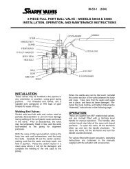
IM-50-1-AAugust 14, 2007Page 4 of 45. Turn the h<strong>and</strong>le to the CLOSED position. Line up the ball slot with the stem tang <strong>and</strong>the ball into position on the stem tang. Turn the h<strong>and</strong>le to the OPEN position to holdthe ball in place.6. Install the remaining seat into body end.7. Place new body seal into counterbore in valve body.8. Put body end into body <strong>and</strong> align the flange bolt holes to straddle the valve centerlines.Note: Be careful not to damage body seal when putting end into body.9. Install body end nuts <strong>and</strong> tighten in a "Star" pattern to the torque specified in Table 2.Take care to make sure that complete engagement of studs with body flange ismaintained. There should be at least one stud thread exposed on each side.10. Cycle the valve open <strong>and</strong> closed several times slowly to ensure that operation issmooth <strong>and</strong> free of binding or sticking.11. Pressure test valve, if possible, before reinstalling in pipeline.Table 1 - Stem Nut TorquesValve Size Torque (lb-ft)½” 5.5¾” 5.51” 61-1/2” – 4” 22Table 2 – Body Bolting Torques (lb-ft)Valve Size Class 150 Class 300 Class 600½” 5 10 15¾” 5 10 201” 5 20 351-1/2” 15 35 802” 20 40 1403” 20 60 1554” 25 95 215Note: Torque values are for TFE/RTFE or flexible graphite gaskets <strong>and</strong> seals. Forother materials contact Sharpe <strong>Valves</strong>.