Installation, Operation, and Maintenance Manual ... - Sharpe® Valves
Installation, Operation, and Maintenance Manual ... - Sharpe® Valves
Installation, Operation, and Maintenance Manual ... - Sharpe® Valves

You also want an ePaper? Increase the reach of your titles
YUMPU automatically turns print PDFs into web optimized ePapers that Google loves.
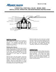
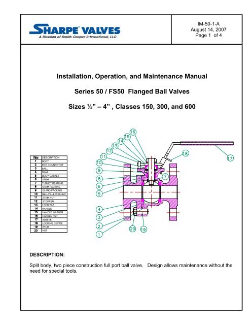
IM-50-1-AAugust 14, 2007Page 1 of 4<strong>Installation</strong>, <strong>Operation</strong>, <strong>and</strong> <strong>Maintenance</strong> <strong>Manual</strong>Series 50 / FS50 Flanged Ball <strong>Valves</strong>Sizes ½” – 4” , Classes 150, 300, <strong>and</strong> 600DESCRIPTIONBODYEND CONNECTORBALLSEATBODY GASKETSTEMTHRUST BEARINGSTEM PACKINGGLAND PACKINGBELLVILLE WASHERSTEM NUTSTOPPERLOCK TABHANDLEHANDLE WASHERHANDLE NUTSLEEVELOCKING DEVICESTUDNUTDESCRIPTION:Split body, two piece construction full port ball valve. Design allows maintenance without theneed for special tools.
IM-50-1-AAugust 14, 2007Page 2 of 4INSTALLATION:1. Before installing the valves, the pipes must be flushed clean of dirt, burrs <strong>and</strong> weldingresidues, or you will damage the seats <strong>and</strong> ball surface.2. These valves may be installed in any position using good pipe fitting practices. Flangesconform to ASME St<strong>and</strong>ard B16.5, Class 150, 300, or 600.3. Periodically check <strong>and</strong> tighten body joint <strong>and</strong> flange bolting. (See TABLE 1 for torquerequirements.)MANUAL OPERATION:1. The valve is opened <strong>and</strong> closed by turning the h<strong>and</strong>le ¼ turn (90°). Turning the h<strong>and</strong>leclockwise closes the valve (h<strong>and</strong>le perpendicular to pipeline). Turning the h<strong>and</strong>lecounterclockwise opens the valve (h<strong>and</strong>le parallel to pipeline).AUTOMATED OPERATION:1. <strong>Valves</strong> with Actuators should be checked for alignment of the actuator to the valve.Angular or parallel misalignment may result in high operational torque, <strong>and</strong> potentialdamage to the stem seals or stem.STEM SEAL ADJUSTMENT:1. Stem seal leakage may be corrected without disassembly. If leakage is evident in stempacking area, tighten the adjusting nut 1/4 turn. If leakage persists, repeat above.Replacement of stem seals is indicated if the leak is still apparent after 1/2 turn.DISASSEMBLY:-CAUTION-If the Valve has been used to control hazardous media, it must be decontaminated beforedisassembly.---WARNING---Do not attempt to repair or partially disassemble a valve while it is in line <strong>and</strong> under pressure.Isolate the line, de-pressurize, <strong>and</strong> remove valve prior to performing maintenance.1. Remove flange bolts <strong>and</strong> nuts <strong>and</strong> lift valve from line. Care should be taken to avoidscratching or damaging flange facings.2. Remove h<strong>and</strong>le <strong>and</strong> travel stop plate.
IM-50-1-AAugust 14, 2007Page 3 of 43. Remove stem nut locking tab, stem nut, belleville springs, <strong>and</strong> gl<strong>and</strong> ring from stem.4. Remove body end nuts, using proper wrench size. Lift off body end. One seat shouldcome out with body end.5. Remove body seal.6. To take out the ball, rotate stem so ball is in fully closed position. Carefully lift ball offstem tang <strong>and</strong> from body with a “rolling” motion. Use a strap <strong>and</strong> lift device, ifnecessary. Note: Extreme caution should be taken to avoid damage to the ball.7. Take out other seat.8. Stem must be removed from inside the body. The thrust bearing should come out withthe stem. Then remove the stem packing.VISUAL INSPECTION:1. Clean <strong>and</strong> inspect all metal parts. Replace the ball <strong>and</strong>/or stem if the seating or sealingsurfaces have been damaged, worn, or corroded.2. Stem seals, seats, <strong>and</strong> body seal must be replaced whenever the valve isdisassembled to avoid seal leakage <strong>and</strong> ensure proper performance.ASSEMBLY:Note: The valve may be assembled <strong>and</strong> operated dry where no lubricants are allowed in thesystem; however, a light lubrication of mating parts will aid in assembly <strong>and</strong> reduce initialoperating torque. Lubricant used must be compatible with the intended line fluid.1. Install one seat in the body cavity with the spherical curvature facing the ball.2. Install thrust bearing on stem <strong>and</strong> slide the stem up through the body.3. Install new stem seals, gl<strong>and</strong> ring, <strong>and</strong> belleville springs. Install stem nut <strong>and</strong> tighten tothe torque values given in Table 1. Install stem nut locking tab or cap. Tighten stemnut slightly if necessary to align nut with locking device surfaces.4. Install travel stop (if supplied) <strong>and</strong> h<strong>and</strong>le. Make sure h<strong>and</strong>le aligns with flow borethrough ball. Install h<strong>and</strong> retainer nut (or capscrew).
IM-50-1-AAugust 14, 2007Page 4 of 45. Turn the h<strong>and</strong>le to the CLOSED position. Line up the ball slot with the stem tang <strong>and</strong>the ball into position on the stem tang. Turn the h<strong>and</strong>le to the OPEN position to holdthe ball in place.6. Install the remaining seat into body end.7. Place new body seal into counterbore in valve body.8. Put body end into body <strong>and</strong> align the flange bolt holes to straddle the valve centerlines.Note: Be careful not to damage body seal when putting end into body.9. Install body end nuts <strong>and</strong> tighten in a "Star" pattern to the torque specified in Table 2.Take care to make sure that complete engagement of studs with body flange ismaintained. There should be at least one stud thread exposed on each side.10. Cycle the valve open <strong>and</strong> closed several times slowly to ensure that operation issmooth <strong>and</strong> free of binding or sticking.11. Pressure test valve, if possible, before reinstalling in pipeline.Table 1 - Stem Nut TorquesValve Size Torque (lb-ft)½” 5.5¾” 5.51” 61-1/2” – 4” 22Table 2 – Body Bolting Torques (lb-ft)Valve Size Class 150 Class 300 Class 600½” 5 10 15¾” 5 10 201” 5 20 351-1/2” 15 35 802” 20 40 1403” 20 60 1554” 25 95 215Note: Torque values are for TFE/RTFE or flexible graphite gaskets <strong>and</strong> seals. Forother materials contact Sharpe <strong>Valves</strong>.