i agree and wish to proceed with download - Roland Systems Group ...
i agree and wish to proceed with download - Roland Systems Group ...
i agree and wish to proceed with download - Roland Systems Group ...

Create successful ePaper yourself
Turn your PDF publications into a flip-book with our unique Google optimized e-Paper software.
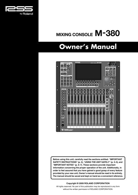
Owner’s ManualBefore using this unit, carefully read the sections entitled: “IMPORTANTSAFETY INSTRUCTIONS” (p. 2), “USING THE UNIT SAFELY” (p. 3–5), <strong>and</strong>“IMPORTANT NOTES” (p. 6–7). These sections provide importantinformation concerning the proper operation of the unit. Additionally, inorder <strong>to</strong> feel assured that you have gained a good grasp of every featureprovided by your new unit, Owner’s manual should be read in its entirety.The manual should be saved <strong>and</strong> kept on h<strong>and</strong> as a convenient reference.Copyright © 2009 ROLAND CORPORATIONAll rights reserved. No part of this publication may be reproduced in any form<strong>with</strong>out the written permission of ROLAND CORPORATION.
WARNING: To reduce the risk of fire or electric shock, do not expose this apparatus <strong>to</strong> rain or moisture.CAUTIONRISK OF ELECTRIC SHOCKDO NOT OPENATTENTION: RISQUE DE CHOC ELECTRIQUE NE PAS OUVRIRCAUTION: TO REDUCE THE RISK OF ELECTRIC SHOCK,DO NOT REMOVE COVER (OR BACK).NO USER-SERVICEABLE PARTS INSIDE.REFER SERVICING TO QUALIFIED SERVICE PERSONNEL.The lightning flash <strong>with</strong> arrowhead symbol, <strong>with</strong>in anequilateral triangle, is intended <strong>to</strong> alert the user <strong>to</strong> thepresence of uninsulated “dangerous voltage” <strong>with</strong>in theproduct’s enclosure that may be of sufficient magnitude <strong>to</strong>constitute a risk of electric shock <strong>to</strong> persons.The exclamation point <strong>with</strong>in an equilateral triangle isintended <strong>to</strong> alert the user <strong>to</strong> the presence of importan<strong>to</strong>perating <strong>and</strong> maintenance (servicing) instructions in theliterature accompanying the product.INSTRUCTIONS PERTAINING TO A RISK OF FIRE, ELECTRIC SHOCK, OR INJURY TO PERSONS.IMPORTANT SAFETY INSTRUCTIONSSAVE THESE INSTRUCTIONSWARNING - When using electric products, basic precautions should always be followed, including the following:1. Read these instructions.2. Keep these instructions.3. Heed all warnings.4. Follow all instructions.5. Do not use this apparatus near water.6. Clean only <strong>with</strong> a dry cloth.7. Do not block any of the ventilation openings. Install inaccordance <strong>with</strong> the manufacturers instructions.8. Do not install near any heat sources such as radia<strong>to</strong>rs,heat registers, s<strong>to</strong>ves, or other apparatus (includingamplifiers) that produce heat.9. Do not defeat the safety purpose of the polarized orgrounding-type plug. A polarized plug has two blades <strong>with</strong>one wider than the other. A grounding type plug has twoblades <strong>and</strong> a third grounding prong. The wide blade or thethird prong are provided for your safety. If the provided plugdoes not fit in<strong>to</strong> your outlet, consult an electrician forreplacement of the obsolete outlet.10. Protect the power cord from being walked on or pinchedparticularly at plugs, convenience receptacles, <strong>and</strong> thepoint where they exit from the apparatus.11. Only use attachments/accessories specifiedby the manufacturer.12. Unplug this apparatus during lightning s<strong>to</strong>rms or whenunused for long periods of time.13. Refer all servicing <strong>to</strong> qualified service personnel. Servicingis required when the apparatus has been damaged in anyway, such as power-supply cord or plug is damaged, liquidhas been spilled or objects have fallen in<strong>to</strong> the apparatus,the apparatus has been exposed <strong>to</strong> rain or moisture, doesnot operate normally, or has been dropped.WARNING:IMPORTANT:For the U.K.THIS APPARATUS MUST BE EARTHEDTHE WIRES IN THIS MAINS LEAD ARE COLOURED IN ACCORDANCE WITH THE FOLLOWING CODE.GREEN-AND-YELLOW: EARTH, BLUE: NEUTRAL, BROWN: LIVEAs the colours of the wires in the mains lead of this apparatus may not correspond <strong>with</strong> the coloured markings identifyingthe terminals in your plug, <strong>proceed</strong> as follows:The wire which is coloured GREEN-AND-YELLOW must be connected <strong>to</strong> the terminal in the plug which is marked by theletter E or by the safety earth symbol or coloured GREEN or GREEN-AND-YELLOW.The wire which is coloured BLUE must be connected <strong>to</strong> the terminal which is marked <strong>with</strong> the letter N or coloured BLACK.The wire which is coloured BROWN must be connected <strong>to</strong> the terminal which is marked <strong>with</strong> the letter L or coloured RED.CAUTION: Danger of explosion if battery is incorrectly replaced.Replace only <strong>with</strong> same or equivalent type.2
USING THE UNIT SAFELYUsed for instructions intended <strong>to</strong> alertthe user <strong>to</strong> the risk of death or severeinjury should the unit be usedimproperly.Used for instructions intended <strong>to</strong> alertthe user <strong>to</strong> the risk of injury or materialdamage should the unit be usedimproperly.* Material damage refers <strong>to</strong> damage orother adverse effects caused <strong>with</strong>respect <strong>to</strong> the home <strong>and</strong> all itsfurnishings, as well <strong>to</strong> domesticanimals or pets.The symbol alerts the user <strong>to</strong> important instructionsor warnings.The specific meaning of the symbol isdetermined by the design contained <strong>with</strong>in thetriangle. In the case of the symbol at left, it is used forgeneral cautions, warnings, or alerts <strong>to</strong> danger.The symbol alerts the user <strong>to</strong> items that must neverbe carried out (are forbidden). The specific thing thatmust not be done is indicated by the design contained<strong>with</strong>in the circle. In the case of the symbol at left, itmeans that the unit must never be disassembled.The ● symbol alerts the user <strong>to</strong> things that must becarried out. The specific thing that must be done isindicated by the design contained <strong>with</strong>in the circle. Inthe case of the symbol at left, it means that the powercordplug must be unplugged from the outlet.001-50• Connect mains plug of this model <strong>to</strong> a mainssocket outlet <strong>with</strong> a protective earthingconnection...........................................................................................................002a• Do not open or perform any internal modificationson the unit...........................................................................................................003• Do not attempt <strong>to</strong> repair the unit, or replace parts<strong>with</strong>in it (except when this manual providesspecific instructions directing you <strong>to</strong> do so). Referall servicing <strong>to</strong> your retailer, the nearest Rol<strong>and</strong> ServiceCenter, or an authorized Rol<strong>and</strong> distribu<strong>to</strong>r, as listed onthe “Information” page...........................................................................................................004• Never use or s<strong>to</strong>re the unit in places that are:• Subject <strong>to</strong> temperature extremes (e.g., directsunlight in an enclosed vehicle, near a heatingduct, on <strong>to</strong>p of heat-generating equipment); orare• Damp (e.g., baths, washrooms, on wet floors);or are• Humid; or are• Exposed <strong>to</strong> rain; or are• Dusty; or are• Subject <strong>to</strong> high levels of vibration...........................................................................................................007• Make sure you always have the unit placed so it islevel <strong>and</strong> sure <strong>to</strong> remain stable. Never place it onst<strong>and</strong>s that could wobble, or on inclined surfaces...........................................................................................................008a• The unit should be connected <strong>to</strong> a power supplyonly of the type described in the operatinginstructions, or as marked on the rear side of unit...........................................................................................................008e• Use only the attached power-supply cord. Also,the supplied power cord must not be used <strong>with</strong>any other device...........................................................................................................009• Do not excessively twist or bend the power cord,nor place heavy objects on it. Doing so c<strong>and</strong>amage the cord, producing severed elements<strong>and</strong> short circuits. Damaged cords are fire <strong>and</strong>shock hazards!..........................................................................................................010• This unit, either alone or in combination <strong>with</strong> anamplifier <strong>and</strong> headphones or speakers, may becapable of producing sound levels that couldcause permanent hearing loss. Do not operate fora long period of time at a high volume level, or ata level that is uncomfortable. If you experienceany hearing loss or ringing in the ears, you shouldimmediately s<strong>to</strong>p using the unit, <strong>and</strong> consult anaudiologist...........................................................................................................011• Do not allow any objects (e.g., flammablematerial, coins, pins); or liquids of any kind(water, soft drinks, etc.) <strong>to</strong> penetrate the unit...........................................................................................................3
012a• Immediately turn the power off, remove thepower cord from the outlet, <strong>and</strong> request servicingby your retailer, the nearest Rol<strong>and</strong> ServiceCenter, or an authorized Rol<strong>and</strong> distribu<strong>to</strong>r, aslisted on the “Information” page when:• The power-supply cord or the plug has been damaged;or• If smoke or unusual odor occurs• Objects have fallen in<strong>to</strong>, or liquid has been spilled on<strong>to</strong>the unit; or• The unit has been exposed <strong>to</strong> rain (or otherwise hasbecome wet); or• The unit does not appear <strong>to</strong> operate normally orexhibits a marked change in performance...........................................................................................................013• In households <strong>with</strong> small children, an adultshould provide supervision until the child iscapable of following all the rules essential for thesafe operation of the unit...........................................................................................................014• Protect the unit from strong impact.(Do not drop it!)..........................................................................................................015• Do not force the unit’s power-supply cord <strong>to</strong>share an outlet <strong>with</strong> an unreasonable number ofother devices. Be especially careful when usingextension cords—the <strong>to</strong>tal power used by alldevices you have connected <strong>to</strong> the extensioncord’s outlet must never exceed the power rating(watts/amperes) for the extension cord. Excessiveloads can cause the insulation on the cord <strong>to</strong> heatup <strong>and</strong> eventually melt through...........................................................................................................016• Before using the unit in a foreign country, consult<strong>with</strong> your retailer, the nearest Rol<strong>and</strong> ServiceCenter, or an authorized Rol<strong>and</strong> distribu<strong>to</strong>r, aslisted on the “Information” page...........................................................................................................020• Keep lithium batteries out of reach of smallchildren. If a child has accidentally swallowed abattery, see a doc<strong>to</strong>r immediately...........................................................................................................021• Lithium batteries must never be recharged,heated, taken apart, or thrown in<strong>to</strong> a fire or water...........................................................................................................026• Do not put anything that contains water (e.g.,flower vases) on this unit. Also, avoid the use ofinsecticides, perfumes, alcohol, nail polish, spraycans, etc., near the unit. Swiftly wipe away anyliquid that spills on the unit using a dry, softcloth...........................................................................................................027• Never expose Lithium Battery <strong>to</strong> excessive heatsuch as sunshine, fire or the like...........................................................................................................101a• The unit should be located so that its location orposition does not interfere <strong>with</strong> its proper ventilation...........................................................................................................102b• Always grasp only the plug on the power-supplycord when plugging in<strong>to</strong>, or unplugging from, anoutlet or this unit...........................................................................................................103a• At regular intervals, you should unplug thepower plug <strong>and</strong> clean it by using a dry cloth <strong>to</strong>wipe all dust <strong>and</strong> other accumulations away fromits prongs. Also, disconnect the power plug fromthe power outlet whenever the unit is <strong>to</strong> remainunused for an extended period of time. Anyaccumulation of dust between the power plug<strong>and</strong> the power outlet can result in poor insulation<strong>and</strong> lead <strong>to</strong> fire...........................................................................................................104• Try <strong>to</strong> prevent cords <strong>and</strong> cables from becomingentangled. Also, all cords <strong>and</strong> cables should beplaced so they are out of the reach of children...........................................................................................................106• Never climb on <strong>to</strong>p of, nor place heavy objects onthe unit...........................................................................................................107b• Never h<strong>and</strong>le the power cord or its plugs <strong>with</strong>wet h<strong>and</strong>s when plugging in<strong>to</strong>, or unpluggingfrom, an outlet or this unit...........................................................................................................108a• Before moving the unit, disconnect the powerplug from the outlet, <strong>and</strong> pull out all cords fromexternal devices...........................................................................................................109a• Before cleaning the unit, turn off the power <strong>and</strong>unplug the power cord from the outlet (p. 18)...........................................................................................................110a• Whenever you suspect the possibility of lightningin your area, pull the plug on the power cord ou<strong>to</strong>f the outlet...........................................................................................................113• Use only the specified type (model no. CR2032) oflithium battery (p. 19). Be sure <strong>to</strong> insert it asdirected (<strong>to</strong> ensure correct polarity)...........................................................................................................114• Used lithium batteries must be disposed of incompliance <strong>with</strong> whatever regulations for theirsafe disposal that may be observed in the regionin which you live...........................................................................................................118c• Keep the USB memory cover, the REAC caps, thegrounding terminal screw, the lithium battery, thebattery panel, the battery panel screws, the powercord hook, the power cord screws <strong>and</strong> any faderknobs you may remove <strong>and</strong> the included theREAC connec<strong>to</strong>r <strong>and</strong> the ferrite cores in a safeplace out of children’s reach, so there is no chanceof them being swallowed accidentally...........................................................................................................4
120• Always turn the phan<strong>to</strong>m power off whenconnecting any device other than condensermicrophones that require phan<strong>to</strong>m power. Yourisk causing damage if you mistakenly supplyphan<strong>to</strong>m power <strong>to</strong> dynamic microphones, audioplayback devices, or other devices that don’trequire such power. Be sure <strong>to</strong> check the specificationsof any microphone you intend <strong>to</strong> use byreferring <strong>to</strong> the manual that came <strong>with</strong> it.(This instrument’s phan<strong>to</strong>m power: +48V DC,14mA Max)..........................................................................................................5
IMPORTANT NOTES291bIn addition <strong>to</strong> the items listed under “IMPORTANTSAFETY INSTRUCTIONS” <strong>and</strong> “USING THE UNITSAFELY” on pages P. 2 <strong>and</strong> P. 3, please read <strong>and</strong>observe the following:Power Supply301• Do not connect this unit <strong>to</strong> same electrical outlet that isbeing used by an electrical appliance that is controlled byan inverter (such as a refrigera<strong>to</strong>r, washing machine,microwave oven, or air conditioner), or that contains amo<strong>to</strong>r. Depending on the way in which the electricalappliance is used, power supply noise may cause this unit<strong>to</strong> malfunction or may produce audible noise. If it is notpractical <strong>to</strong> use a separate electrical outlet, connect apower supply noise filter between this unit <strong>and</strong> theelectrical outlet.307• Before connecting this unit <strong>to</strong> other devices, turn off thepower <strong>to</strong> all units. This will help prevent malfunctions<strong>and</strong>/or damage <strong>to</strong> speakers or other devices.308• Although the LCD <strong>and</strong> LEDs are switched off when thePOWER switch is switched off, this does not mean that theunit has been completely disconnected from the source ofpower. If you need <strong>to</strong> turn off the power completely, firstturn off the POWER switch, then unplug the power cordfrom the power outlet. For this reason, the outlet in<strong>to</strong>which you choose <strong>to</strong> connect the power cord’s plugshould be one that is <strong>with</strong>in easy reach <strong>and</strong> readily accessible.Placement351• Using the unit near power amplifiers (or other equipmentcontaining large power transformers) may induce hum.To alleviate the problem, change the orientation of thisunit; or move it farther away from the source of interference.352a• This device may interfere <strong>with</strong> radio <strong>and</strong> televisionreception. Do not use this device in the vicinity of suchreceivers.352b• Noise may be produced if wireless communicationsdevices, such as cell phones, are operated in the vicinity ofthis unit. Such noise could occur when receiving or initiatinga call, or while conversing. Should you experiencesuch problems, you should relocate such wireless devicesso they are at a greater distance from this unit, or switchthem off.354a• Do not expose the unit <strong>to</strong> direct sunlight, place it neardevices that radiate heat, leave it inside an enclosedvehicle, or otherwise subject it <strong>to</strong> temperature extremes.Excessive heat can deform or discolor the unit.355b• When moved from one location <strong>to</strong> another where thetemperature <strong>and</strong>/or humidity is very different, waterdroplets (condensation) may form inside the unit. Damageor malfunction may result if you attempt <strong>to</strong> use the unit inthis condition. Therefore, before using the unit, you mustallow it <strong>to</strong> st<strong>and</strong> for several hours, until the condensationhas completely evaporated.360• Depending on the material <strong>and</strong> temperature of the surfaceon which you place the unit, its rubber feet may discoloror mar the surface.You can place a piece of felt or cloth under the rubber feet<strong>to</strong> prevent this from happening. If you do so, please makesure that the unit will not slip or move accidentally.Maintenance401a• For everyday cleaning wipe the unit <strong>with</strong> a soft, dry clothor one that has been slightly dampened <strong>with</strong> water. Toremove stubborn dirt, use a cloth impregnated <strong>with</strong> amild, non-abrasive detergent. Afterwards, be sure <strong>to</strong> wipethe unit thoroughly <strong>with</strong> a soft, dry cloth.402• Never use benzine, thinners, alcohol or solvents of anykind, <strong>to</strong> avoid the possibility of discoloration <strong>and</strong>/ordeformation.Repairs <strong>and</strong> Data452• Please be aware that all data contained in the unit’smemory may be lost when the unit is sent for repairs.Important data should always be backed up on a USBmemory, or written down on paper (when possible).During repairs, due care is taken <strong>to</strong> avoid the loss of data.However, in certain cases (such as when circuitry related<strong>to</strong> memory itself is out of order), we regret that it may notbe possible <strong>to</strong> res<strong>to</strong>re the data, <strong>and</strong> Rol<strong>and</strong> assumes noliability concerning such loss of data.6
IMPORTANT NOTESMemory Backup501b• This unit contains a battery which powers the unit’smemory circuits while the main power is off. When thisbattery becomes weak, the message shown below willappear in the display. Once you see this message, have thebattery replaced <strong>with</strong> a fresh one as soon as possible <strong>to</strong>avoid the loss of all data in memory. To have the batteryreplaced, consult <strong>with</strong> your retailer, the nearest Rol<strong>and</strong>Service Center, or an authorized Rol<strong>and</strong> distribu<strong>to</strong>r, aslisted on the “Information” page.Additional Precautions551• Please be aware that the contents of memory can beirretrievably lost as a result of a malfunction, or theimproper operation of the unit. To protect yourself againstthe risk of loosing important data, we recommend thatyou periodically save a backup copy of important datayou have s<strong>to</strong>red in the unit’s memory on a USB memory.552• Unfortunately, it may be impossible <strong>to</strong> res<strong>to</strong>re the contentsof data that was s<strong>to</strong>red on a USB memory once it has beenlost. Rol<strong>and</strong> Corporation assumes no liability concerningsuch loss of data.553• Use a reasonable amount of care when using the unit’sbut<strong>to</strong>ns, sliders, or other controls; <strong>and</strong> when using its jacks<strong>and</strong> connec<strong>to</strong>rs. Rough h<strong>and</strong>ling can lead <strong>to</strong> malfunctions.554• Never strike or apply strong pressure <strong>to</strong> the display.556• When connecting / disconnecting all cables, grasp theconnec<strong>to</strong>r itself—never pull on the cable. This way youwill avoid causing shorts, or damage <strong>to</strong> the cable’sinternal elements.557• A small amount of heat will radiate from the unit duringnormal operation.558b• To avoid disturbing your neighbors, try <strong>to</strong> keep the unit’svolume at reasonable levels (especially when it is late atnight).559a• When you need <strong>to</strong> transport the unit, package it in the box(including padding) that it came in, if possible. Otherwise,you will need <strong>to</strong> use equivalent packaging materials.562• Some connection cables contain resis<strong>to</strong>rs. Do not usecables that incorporate resis<strong>to</strong>rs for connecting <strong>to</strong> this unit.The use of such cables can cause the sound level <strong>to</strong> beextremely low, or impossible <strong>to</strong> hear. For information oncable specifications, contact the manufacturer of the cable.xxx• The M-380’s center of gravity is located <strong>to</strong>ward the rear ofthe unit. When transporting the M-380, grasp it firmly <strong>and</strong>be careful not <strong>to</strong> let it fall.xxx• If the display becomes extremely dim, it is possible thatthe display backlight has malfunctioned. If this occurs,you must contact your dealer or a Rol<strong>and</strong> service center.xxx• Due <strong>to</strong> the nature of the display, there may be screenpixels that remain lit or that fail <strong>to</strong> light; please be awarethat this is not a malfunction or a defect.Before Using USB memoryUsing USB memory704• Carefully insert the USB memory all the way in—until it isfirmly in place.705• Never <strong>to</strong>uch the terminals of the USB memory. Also,avoid getting the terminals dirty.708• USB memories are constructed using precision components;h<strong>and</strong>le the cards carefully, paying particular note <strong>to</strong>the following.• To prevent damage <strong>to</strong> the cards from static electricity,be sure <strong>to</strong> discharge any static electricity from yourown body before h<strong>and</strong>ling the cards.• Do not <strong>to</strong>uch or allow metal <strong>to</strong> come in<strong>to</strong> contact <strong>with</strong>the contact portion of the cards.• Do not bend, drop, or subject cards <strong>to</strong> strong shock orvibration.• Do not keep cards in direct sunlight, in closed vehicles, orother such locations (s<strong>to</strong>rage temperature: -25 <strong>to</strong> 85˚ C).• Do not allow cards <strong>to</strong> become wet.• Do not disassemble or modify the cards.About USB memory• Before using USB memory for the M-380, please formatthe memory on the M-380.For details, please refer “Formatting USB memory” (p.177).• Some USB memory might not be able <strong>to</strong> be used on the M-380.If there would be an error message by processing formatin accordance <strong>with</strong> “Formatting USB memory” (p. 177), itis not possible <strong>to</strong> use for the M-380.• The M-380 supports only USB memory (USB flashMemory <strong>and</strong> USB flash drive).Hard Disk <strong>and</strong> Memory Card Reader via USB is notsupported.• USB memory does not work via USB hub.• When the access lamp of USB memory is lit or blinked,please do not remove the USB memory.This might cause some damage <strong>to</strong> the data of the USBmemory or dificit.• We recommend <strong>to</strong> format USB memory before doingmixing operation on the M-380.• We recommend <strong>to</strong> use USB memory exclusively for the M-400/M-380 <strong>with</strong>out s<strong>to</strong>ring any other files or programs.7
IMPORTANT NOTESRegarding the CAT5e cable• In order <strong>to</strong> keep superb digital transfer quality by REAC,please make sure <strong>to</strong> use following optional cables for 100 mCAT5e cable.SC-W100S 100M CAT5e cableW100S-R 100M CAT5e cable <strong>with</strong> reelfor 100 m CAT5e cable.Channel Edit operation• You might find some noises when you control followings.However, this is not out of order.Preamp Gain4-b<strong>and</strong> EQGateComp/LimiterChannel LinkLibrary RecallMultiple connection of REACproducts• When multiple REAC products are connected <strong>to</strong> eitherREAC A or REAC B on the M-400/M-380 via REACsplitter or switching hub, please set up REAC mode oneach product correctly.If you turn on the power of these products <strong>with</strong> REACmode setting incorrectly, there might be some digitalnoises happened from REAC products or M-380.If this would happen, please turn off the power of allREAC products <strong>and</strong> set the REAC mode correctly.Copyright851• Recording, duplication, distribution, sale, lease, performance,or broadcast of copyrighted material (musicalworks, visual works, broadcasts, live performances, etc.)belonging <strong>to</strong> a third party in part or in whole <strong>with</strong>out thepermission of the copyright owner is forbidden by law.853• Do not use this unit for purposes that could infringe on acopyright held by a third party. We assume no responsibilitywhatsoever <strong>with</strong> regard <strong>to</strong> any infringements ofthird-party copyrights arising through your use of thisunit.204* Microsoft <strong>and</strong> Windows are registered trademarks ofMicrosoft Corporation.206j* Windows ® is known officially as: “Microsoft ® Windows ®operating system.”* Neutrik <strong>and</strong> EtherCon are registered trademarks ofNeutrik, Inc• MMP (Moore Microprocessor Portfolio) refers <strong>to</strong> a patentportfolio concerned <strong>with</strong> microprocessor architecture,which was developed by Technology Properties Limited(TPL). Rol<strong>and</strong> has licensed this technology from the TPL<strong>Group</strong>.236• Fugue © 2009 Kyo<strong>to</strong> Software Research, Inc. All rightsreserved.220* All product names mentioned in this document are trademarksor registered trademarks of their respective owners.8
IMPORTANT NOTES9
ContentsDynamics ...............................................................................................73Gate/exp<strong>and</strong>er operations...................................................................................................................... 73Compressor operations............................................................................................................................ 78Limiter operations (MAIN L/R, AUX1–AUX16)................................................................................. 82Four-b<strong>and</strong> EQ ........................................................................................84Four-b<strong>and</strong> EQ operations........................................................................................................................ 84AUX send/MATRIX send.......................................................................87AUX send operations............................................................................................................................... 87MATRIX send operations........................................................................................................................ 89Input/output patchbay ..........................................................................90Default settings of the input/output patchbay.................................................................................... 90Patchbay operations................................................................................................................................. 90Input patchbay operations ...................................................................................................................... 91Output patchbay operations................................................................................................................... 92Metering .................................................................................................94About the meters ...................................................................................................................................... 94Viewing the meters .................................................................................................................................. 94Viewing the channel strip of the channel layer.................................................................................... 95Editing the meter settings ....................................................................................................................... 96Using the analyzer.................................................................................................................................... 96Listing the channel names <strong>and</strong> group names.......................................................................................97Effects <strong>and</strong> 31-b<strong>and</strong> GEQ.....................................................................98About effects ............................................................................................................................................. 98Effect input/output settings ................................................................................................................. 100Editing effect parameters ...................................................................................................................... 102About the 31-b<strong>and</strong> GEQ ........................................................................................................................ 104Inserting a 31-b<strong>and</strong> GEQ ....................................................................................................................... 105Editing the 31-b<strong>and</strong> GEQ parameters ................................................................................................. 106Inserting an external effects device ..................................................111About inserting an external effects device.......................................................................................... 111Inserting an external effects device in<strong>to</strong> a channel............................................................................ 112DCA groups .........................................................................................114About DCA groups ................................................................................................................................ 114DCA group settings ............................................................................................................................... 114Assigning a channel <strong>to</strong> a DCA group.................................................................................................. 115Specifying a name <strong>and</strong> color label for the DCA group..................................................................... 115Using the panel <strong>to</strong> control DCA groups.............................................................................................. 116Mute groups ........................................................................................117About mute groups ................................................................................................................................ 117Assigning a channel <strong>to</strong> a mute group.................................................................................................. 117Specifying a name <strong>and</strong> color label for a mute group ........................................................................ 118Talkback/Oscilla<strong>to</strong>r .............................................................................119About talkback <strong>and</strong> oscilla<strong>to</strong>r............................................................................................................... 119Using talkback......................................................................................................................................... 120Using the oscilla<strong>to</strong>r................................................................................................................................. 121Moni<strong>to</strong>r/Solo ........................................................................................122About moni<strong>to</strong>ring................................................................................................................................... 122Using Moni<strong>to</strong>r......................................................................................................................................... 123Using Solo................................................................................................................................................ 124Contents11
ContentsContentsScene memory ....................................................................................125About scene memory ............................................................................................................................. 125Operations in the SCENE screen.......................................................................................................... 125Momentarily displaying the scene list ................................................................................................ 128Editing the scene list .............................................................................................................................. 129The Global Scope function .................................................................................................................... 131Synchronizing scene memories <strong>with</strong> M-48 memories ...................................................................... 132LCR SYSTEM.......................................................................................134About the LCR (Left/Center/Right) SYSTEM................................................................................... 134Making the LCR SYSTEM setting ........................................................................................................ 135Operating MAIN C ................................................................................................................................ 138Sending signals from CH <strong>and</strong> AUX <strong>to</strong> MAIN L/R <strong>and</strong> MAIN C................................................... 138Parameter changes when the LCR SYSTEM is on ............................................................................. 139USB memory recorder........................................................................141About the USB memory recorder......................................................................................................... 141Using the USB memory recorder ......................................................................................................... 141User settings .......................................................................................146About user settings ................................................................................................................................ 146Creating <strong>and</strong> editing user settings ....................................................................................................... 146Limiting the range of possible operations .......................................................................................... 151Editing the user preferences ................................................................................................................. 152Using the user but<strong>to</strong>ns........................................................................................................................... 154Editing other user preferences.............................................................................................................. 155REAC applications <strong>and</strong> settings........................................................157REAC applications ................................................................................................................................. 157REAC connection examples.................................................................................................................. 159REAC settings ......................................................................................................................................... 162Remote.................................................................................................165Remote functions.................................................................................................................................... 165Remote settings....................................................................................................................................... 166Other settings <strong>and</strong> functions .............................................................170Viewing system information <strong>and</strong> making basic mixer settings....................................................... 170Saving <strong>and</strong> loading mixer settings....................................................................................................... 173Date <strong>and</strong> time settings ........................................................................................................................... 175Managing USB memory ........................................................................................................................ 176Console Lock ........................................................................................................................................... 179Help function .......................................................................................................................................... 180System settings........................................................................................................................................ 18112
ContentsManagement of the M-48 live personal mixer ..................................184What is the M-48 live personal mixer? ................................................................................................ 184Connecting M-48 units <strong>to</strong> the M-380 ................................................................................................... 185Editing <strong>and</strong> managing M-48 units ....................................................................................................... 186Specifying the outputs from the M-380 <strong>to</strong> the M-48 unit ................................................................. 186Viewing the connected M-48 units ...................................................................................................... 187Making settings for an M-48 unit......................................................................................................... 190Setting the level, pan, <strong>and</strong> AUX switch for each source(Source Level/Pan setting).................................................................................................................... 193Assigning sources <strong>to</strong> groups (Source Assign settings) ..................................................................... 196Checking <strong>and</strong> adjusting the musician’s mix (<strong>Group</strong> Mix) ............................................................... 198Copying M-48 settings........................................................................................................................... 200M-48 memory operations ...................................................................................................................... 201Using the M-48 library........................................................................................................................... 203Saving/loading USB memory .............................................................................................................. 205Appendix..............................................................................................208User but<strong>to</strong>n functions ............................................................................................................................ 208Error message list ................................................................................................................................... 209Troubleshooting...................................................................................................................................... 210Pin configuration diagrams .................................................................................................................. 212Requirements for switching hubs ........................................................................................................ 212Main specifications................................................................................................................................. 213Dimensions.............................................................................................................................................. 216Reverb ...................................................................................................................................................... 217Delay......................................................................................................................................................... 222Modulation.............................................................................................................................................. 225Pitch shift ................................................................................................................................................. 227Channel strip........................................................................................................................................... 227GEQ .......................................................................................................................................................... 230Rol<strong>and</strong> vintage effects............................................................................................................................ 231Index.....................................................................................................237Screen index........................................................................................240Contents13
IntroductionCheck the included itemsBasic knowledge about REACIntroductionThe following items are included <strong>with</strong> the M-380. Make sure that allof them are present.• The M-380 itself• Power cord* Use only the power cord that was included <strong>with</strong> the M-380.• REAC connec<strong>to</strong>r covers (three)• Channel number sticker• Ferrite cores (four)• Owner’s manual (the document you’re reading)Conventions used in thismanualThe explanations in this manual include illustrations that depictwhat should typically be shown by the display. Note, however, thatyour unit may incorporate a newer, enhanced version of the system(e.g., includes newer sounds), so what you actually see in the displaymay not always match what appears in the manual.NamesThe following input/output units can be connected <strong>to</strong> the M-380’sREAC ports.• S-1608 stage unit• S-0816 FOH unit• S-4000S 40-channel I/O modular rack (Ver. 2.010 <strong>and</strong> later)In this manual, we may abbreviate these units as the S-1608, S-0816,or S-4000S, or may refer <strong>to</strong> them collectively as input/output units.Text enclosed in square brackets [ ] indicates a but<strong>to</strong>n. For example,the direction <strong>to</strong> “press [METER]” means that you are <strong>to</strong> press theMETER but<strong>to</strong>n.If a secondary name is shown for a but<strong>to</strong>n, such as [DISP (BUTTONASSIGN)], the text in parentheses indicates the function that thebut<strong>to</strong>n has when pressed while holding down [SHIFT].In the case of function but<strong>to</strong>ns, the function is given in parentheses,such as [F1 (LINK)].About REACThe REAC (Rol<strong>and</strong> Ethernet Audio Communication) interface is thecore of this system. It uses a proprietary pro<strong>to</strong>col based on Ethernettechnology, <strong>and</strong> allows 40 channels of digital audio <strong>to</strong> be sent via asingle Cat5e Ethernet cable.REAC can do the following.• Send 40 channels of digital audio• Send audio up <strong>to</strong> 100 meters on one Cat5e cable• A switching hub or the S-OPT option can be used <strong>to</strong> extend thecable.• Use a switching hub <strong>to</strong> easily split the signal• The transmission delay between REAC devices is extremelysmall (approximately 375 microseconds)When the signal passes through a switching hub, there will beapproximately 200 microseconds of delay for each unit.About cablesSince Cat5e Ethernet cables are used, it’s very easy <strong>to</strong> connect REACdevices <strong>to</strong> each other. Cat5e Ethernet cables are commonly used forcomputer network connections, <strong>and</strong> have RJ45 plugs.Types of Ethernet cableThere are two types of Ethernet cables. Although both types have thesame exterior appearance, their RJ45 plugs are wired differently, asfollows.• Crossover cableThe internal wiring of the cable is crossed at each RJ45 plug.This means that the connections of the RJ45 plugs will differ ateach end of the cable.• Straight cableThe internal wiring of the cable is the same at each end.Crossover cables (such as RSS SC-W100S or RSS W100S-R) should beused when connecting <strong>to</strong> the REAC ports on this product.Certain cautions apply if you’re using a conventionalswitching hub <strong>with</strong> this system. For details, refer <strong>to</strong> “REACapplications” (p. 157).14
IntroductionEthernet connec<strong>to</strong>rsEthernet cables use RJ45 plugs. REAC equipment provides an RJ45connec<strong>to</strong>r for each REAC port.fig.RJ45<strong>and</strong>REAC-e.epsREAC connectionsHere is a typical example of connections using the S-1608.When connecting REAC devices <strong>to</strong> each other, the REAC mode ofone device must be set <strong>to</strong> Master, <strong>and</strong> the REAC mode of the othersmust be set <strong>to</strong> Slave.In this system, the M-380 is normally set <strong>to</strong> be the master (FOHsetting), while the input/output units are set <strong>to</strong> be slaves.IntroductionFor a more detailed description of connections, refer <strong>to</strong> “REACapplications” (p. 157).RJ45 plugREAC RJ45 connec<strong>to</strong>rFor critically important communication, it is vital <strong>to</strong> protect the RJ45plug <strong>and</strong> connec<strong>to</strong>r. For such situations, REAC RJ45 connec<strong>to</strong>rs use asturdy Neutrik EtherCon plug. Using the EtherCon RJ45 plug allowsa latched-type connec<strong>to</strong>r similar <strong>to</strong> an XLR plug.Neutrik Corporation provides EtherCon RJ45 plugs as well as TheNeutrik Corporation manufactures EtherCon RJ45 plugs, as well asEtherCon plugs that can be added <strong>to</strong> the RJ45 plug of commerciallyavailable Ethernet cable.Cat5e Ethernet cables up <strong>to</strong> 100 meters long are supported. Ifyou need a longer connection, we recommend that you use theoptional S-OPT.fig.connect-REAC.epsS-1608SLAVECat5eS-1608SLAVECat5eThe RJ45 connec<strong>to</strong>rs of REAC ports can accept either RJ45 plugsor EtherCon plugs.REAC AMASTERREAC BMASTERCautions for h<strong>and</strong>ling Cat5e cables• Do not apply excessive force <strong>to</strong> Cat5e cables.• Do not bundle (bend) a Cat5e cable <strong>to</strong> a radius less than 25 mm,or fold it in two.• Do not tightly bundle a Cat5e cable.• Do not place multiple Cat5e cables in parallel for an extendeddistance.• Do not place Cat5e cables near a source of electrical noise(power supply cord, mo<strong>to</strong>r, fluorescent lights, etc.).M-380Cautions when making REACconnections• REAC connections are designed so that noise will not beproduced even if you hot-swap (plug or unplug a liveconnection). However in rare cases, noise may occur at theaudio output of the system. To prevent hot-swapping fromcausing damage <strong>to</strong> your speakers or other equipment connected<strong>to</strong> the audio outputs, please observe the following points.• Make REAC connections while holding down the [MUTE ALLOUTPUTS] of the input/output unit• Before you make REAC connections, mute the outputs using [F6(MUTE ALL OUT)] in the MUTE GROUP screen (p. 117).In some cases, the muted state will continue even after yourelease your finger from [MUTE ALL OUTPUTS] of the input/output unit. In this case, press [MUTE ALL OUTPUTS] onceagain <strong>to</strong> mute, <strong>and</strong> then release your finger <strong>to</strong> unmute the unit.15
IntroductionPlacementAbout the REAC capsIntroductionAttaching the ferrite coreYou must attach the ferrite cores before using the M-380. This is forthe purpose of preventing electromagnetic noise; do not remove it.1. Spread the tabs, <strong>and</strong> open the ferrite core.fig.core1.epsWhen the M-380 is shipped from the fac<strong>to</strong>ry, REAC caps areattached <strong>to</strong> the REAC ports. In order <strong>to</strong> use REAC port, you’ll need<strong>to</strong> remove the REAC cap. Take care not <strong>to</strong> lose the REAC caps youremove.2. Attach a ferrite core near the RJ45 plug on the Ethernetcable, <strong>and</strong> near the base of the coaxial digital cable.fig.core2.epsAbout the REAC connec<strong>to</strong>r coversWhen using an Ethernet cable <strong>with</strong> st<strong>and</strong>ard RJ45 plugs, fit theincluded REAC connec<strong>to</strong>r covers on the REAC ports as shown.3. Close the ferrite core until you hear it snap shut.fig.core3.eps4. Connect the plug <strong>with</strong> the ferrite core <strong>to</strong> the M-380’s REACport.Remove the REAC connec<strong>to</strong>r cover if you’re using an EtherContype REAC cable (SC-W100S/W100S-R). Take care not <strong>to</strong> losethe REAC connec<strong>to</strong>r covers you removed.16
IntroductionWhen Installing in a RackAttaching the power cord hookThis unit can be installed in a rack. When installing the unit in a rack,<strong>to</strong> ensure efficient cooling, give attention <strong>to</strong> the following points.• Ensure that the location provides good air flow <strong>and</strong> ventilation.• Never block the cooling-fan intake port or ventilation port inthe front <strong>and</strong> rear panel.• Avoid using the M-380 in sealed-type rack mounts. As this typeof rack does not permit heated air <strong>with</strong>in the rack <strong>to</strong> beexpelled, the heated air is drawn in<strong>to</strong> the M-380 as a result, thuspreventing adequately efficient cooling.• If the rack’s rear panel is not removable, ensure that aventilation port or exhaust fan is provided at the <strong>to</strong>p of therack’s rear panel <strong>to</strong> expel any accumulated heat.• If the M-380 is mounted in a portable rack, remove both thefront <strong>and</strong> rear rack covers before use <strong>to</strong> ensure that the M-380’sfront <strong>and</strong> rear panels remain unobstructed.• When installing the unit on a rack, detach the rubber feet fromthe bot<strong>to</strong>m of the unit.1. As shown in the illustration, remove the two screws thatfasten the hook, <strong>and</strong> detach the power cord hook.fig.cord-hook1.epsIntroductionUse due caution when mounting the M-380 in a rack or otherenclosure so you don’t get your fingers wedged or pinched.AC power connections2. As shown in the illustration, fit the power cord hook overthe power cord, <strong>and</strong> fasten it using the two screws youremoved in step 1.fig.cord-hook2.epsConnect one end of the supplied AC power cord <strong>to</strong> a grounded ACoutlet, <strong>and</strong> the other end <strong>to</strong> the AC INPUT connec<strong>to</strong>r <strong>to</strong> providepower for the M-380’s internal power supply.Use only the supplied power cords <strong>to</strong> prevent damage <strong>to</strong> theunits.Attaching the power cord clamp1. Lower the power cord clamp <strong>to</strong> fasten the power cord.fig.cord-cramp2.eps17
IntroductionTurning the power on/off6. Turn on the power of the equipment connected <strong>to</strong> the audiooutputs of the M-380 <strong>and</strong> your input/output units.IntroductionTurning the power onOnce the connections have been completed, turn on power <strong>to</strong>your various devices in the order specified. By turning ondevices in the wrong order, you risk causing malfunction <strong>and</strong>/or damage <strong>to</strong> speakers <strong>and</strong> other devices.fig.PowerOnOrder.eps35 6INPUTOUTPUTThis unit is equipped <strong>with</strong> a protection circuit. A brief interval(a few seconds) after power up is required before the unit willoperate normally.Turning the power off1. Mute the outputs using [F6 (MUTE ALL OUT)] in the MUTEGROUP screen (p. 117).2. Turn off the power of the equipment connected <strong>to</strong> the audiooutputs of the M-380 <strong>and</strong> your input/output units.Cat5eM-3801. Connect your input/output units (S-1608, S-0816, S-4000S,etc.) <strong>to</strong> the M-380’s REAC port.2. Connect your audio equipment <strong>to</strong> the audio inputs <strong>and</strong>audio outputs of the M-380 <strong>and</strong> your input/output units.43. Turn off the power using the POWER switch located on theM-380’s rear panel.4. Turn off the power of your input/output units.5. Turn off the power of the equipment connected <strong>to</strong> the audioinputs of the M-380 <strong>and</strong> your input/output units.Before you turn off the power of the M-380, make sure that it isnot reading/writing USB memory or reading/writing scenememory or library data. The data may be destroyed if you turnoff the power during such operations.To prevent malfunction <strong>and</strong>/or damage <strong>to</strong> speakers or otherdevices, always turn down the volume, <strong>and</strong> turn off the poweron all devices before making any connections.Howling could be produced depending on the location ofmicrophones relative <strong>to</strong> speakers. This can be remedied by:1. Changing the orientation of the microphone(s).2. Relocating microphone(s) at a greater distance from speakers.3. Lowering volume levels.3. Turn on the power of the equipment connected <strong>to</strong> the audioinputs of the M-380 <strong>and</strong> your input/output units.4. Turn on the power using the POWER switch located on theM-380’s rear panel.When the power supply has started up, a screen like thefollowing will appear.fig.ScrMeter.eps5. Turn on the power of your input/output units.If your input/output unit is the S-1608 or S-0816, use the powercord included <strong>with</strong> the unit <strong>to</strong> connect the AC inlet of theinput/output unit <strong>to</strong> an electrical outlet.18
IntroductionAbout the internal lithiumbatteryThe M-380 has an internal lithium battery that backs up the clockfunction <strong>and</strong> the mixer settings. If this battery runs down, the clockfunction <strong>and</strong> the feature that provides for the reinstatement of themixer settings that existed prior <strong>to</strong> switching off the power will nolonger operate correctly. If a popup message recommending thatyou replace the battery appears when you turn on the power, replacethe battery as described in the following procedure.Replace the old battery <strong>with</strong> a CR2032 type lithiumbattery. Ask your consumer electronics dealer for a“CR2032 type lithium battery.”1. Back up the M-380’s mixer settings <strong>to</strong> USB memory.For details, refer <strong>to</strong> “Saving mixer settings <strong>to</strong> USB memory” (p.173).2. Switch off the M-380’s power, <strong>and</strong> disconnect the powercord from the AC outlet.3. Remove the two screws that fasten the battery cover asshown in the illustration, <strong>and</strong> detach the battery cover.fig.battery-panel1.epsÀ propos dela pile interneau lithiumLe M-380 est équipé d’une pile au lithium qui fait fonctionnerl’horloge et préserve les réglages du mélangeur. Si la pile est faible,l’horloge et la restauration des réglages du mélangeur nefonctionnent pas correctement. Si un message contextuelrecomm<strong>and</strong>ant de remplacer la pile s’affiche lorsque l’appareil estmis sous tension, il faut la remplacer comme suit.Remplacement de la pile usée par une pile au lithiumde type CR2032. Il faut s’assurer d’obtenir pile aulithium de type CR2032 du détaillant d’appareilsélectroniques.1. Faire une copie de sauvegarde des réglages du mélangeurinterne dans la mémoire USB.Pour obtenir les détails, se reporter à la rubrique “Saving mixersettings <strong>to</strong> USB memory” (p. 173).2. Couper l’alimentation du M-380 et débrancher le câbled’alimentation de la prise de courant.3. Comme le montre l’illustration, retirer les deux vis quiretiennent le couvercle du compartiment de la pile et retirerle couvercle.fig.battery-panel1.epsIntroduction4. Remove the old battery, <strong>and</strong> insert the new battery.5. Attach the battery cover as shown in the illustration, <strong>and</strong>fasten it using the two screws you removed in step 3.fig.battery-panel2.eps4. Retirer la pile usée et insérer la pile neuve.5. Remettre en place le couvercle du compartiment de la pileet le fixer à l’aide des deux vis retirées à l’étape 3.fig.battery-panel2.eps6. Turn on the power of the M-380, <strong>and</strong> set the date <strong>and</strong> time(p. 175).7. Load the previously saved settings (MIXER PARAMETER,SYSTEM SETTING) from the USB memory <strong>to</strong> which youbacked up the data in step 1. (p. 174)6. Mettre le M-380 sous tension et régler la date et l’heure(p. 175).7. Charger les réglages enregistrés (PARAMÈTRE DUMÉLANGEUR, RÉGLAGE DU SYSTÈME) dans lamémoire USB où la copie de sauvagarde a été faite àl’étape 1. (p. 174)19
IntroductionAbout USB memoryIntroductionThe M-380 can use USB memory <strong>to</strong> s<strong>to</strong>re <strong>and</strong> read a variety of data.• Record <strong>and</strong> play WAV files using the USB Memory Recorder• Save <strong>and</strong> load user settings files• Back up <strong>and</strong> recover internal mixer dataCarefully insert the USB memory all the way in---until it isfirmly in place.USB memory used <strong>with</strong> the USB Memory Recorder mustsupport USB 2.0 (Hi-speed).About the USB memory coverThe USB memory connec<strong>to</strong>r is fitted <strong>with</strong> a USB memory cover.When using USB memory, open the USB memory cover. When notusing USB memory, keep the USB memory cover closed.20
IntroductionIntroduction21
Explanation of the panelsTop panelfig.TopPanelGuide.epsExplanation of the panels46 7 895101113 14121 2 317151618191 Fader module section p. 232 Layer section p. 233 Main fader module p. 244 CHANNEL EDIT section p. 245 Display p. 276 Function but<strong>to</strong>n section p. 277 EFFECTS but<strong>to</strong>n p. 278 METER but<strong>to</strong>n p. 279 USER section p. 2710 USB MEMORY RECORDER section p. 2711 SETUP section p. 2812 Screen controller section p. 2813 TALKBACK/OSC section p. 2814 MONITOR section p. 2915 GROUP section p. 2916 SCENE MEMORY section p. 2917 USB MEMORY connec<strong>to</strong>r p. 2918 PHONES jack p. 2919 PHONES LEVEL knob p. 2922
Explanation of the panelsExplanation of the panelsC. AUX1-12 layer but<strong>to</strong>nThis assigns AUX1–AUX12 <strong>to</strong> the fader module section.When the USER layer mode is on, this calls up user layer 5 <strong>to</strong>the fader module section.D. CH37-48 layer but<strong>to</strong>nThis assigns CH37–CH48 <strong>to</strong> the fader module section.When the USER layer mode is on, this calls up user layer 4 <strong>to</strong>the fader module section.E. CH25-36 layer but<strong>to</strong>nThis assigns CH25–CH36 <strong>to</strong> the fader module section.When the USER layer mode is on, this calls up user layer 3 <strong>to</strong>the fader module section.F. CH13-24 layer but<strong>to</strong>nThis assigns CH13–CH24 <strong>to</strong> the fader module section.When the USER layer mode is on, this calls up user layer 2 <strong>to</strong>the fader module section.4. CHANNEL EDIT sectionfig.ChEditSectGuide.epsC A HEFDBGG. CH1-12 layer but<strong>to</strong>nThis assigns CH1–CH12 <strong>to</strong> the fader module section.When the USER layer mode is on, this calls up user layer 1 <strong>to</strong>the fader module section.I3. Main fader modulefig.MainFaderModGuide.epsABCA. SEL but<strong>to</strong>nThis but<strong>to</strong>n selects the MAIN channel so that it can becontrolled from the CHANNEL EDIT section or in the screen. Itwill light if the MAIN channel is selected.In this section you can operate the main parameters of the currentlyselected channel.A. CH DISP but<strong>to</strong>nThis but<strong>to</strong>n accesses the CHANNEL DISPLAY screen. It willlight red while this screen is displayed.B. TOUCH SELECT but<strong>to</strong>nThis but<strong>to</strong>n turns the Touch Select function on/off. It will lightif the Touch Select function is on.The Touch Select function lets you select a channel by <strong>to</strong>uchingits fader.By repeatedly pressing [SEL] you can alternately select theMAIN L or MAIN R channels.B. SOLO but<strong>to</strong>nThis but<strong>to</strong>n turns solo on/off for the MAIN L/R channels. Itwill light if solo is on.C. FaderThis adjusts the signal level of the MAIN L/R channels.24
Explanation of the panelsC. PREAMP areafig.ChEdtPreamp.epsE. GATE areafig.ChEdtGate.eps• GAIN knobThis adjusts the preamp gain of CH1–CH48.This adjusts the attenua<strong>to</strong>r of AUX1–AUX16, MATRIX1–MATRIX8, MAIN L/R <strong>and</strong> MAIN C.When ATT Ctrl (p. 50) at the CHANNEL DISPLAY screen is on,this always adjusts the attenua<strong>to</strong>r.This control is invalid for the following channels.• Input channels <strong>to</strong> which you have not patched an input port• Input channels <strong>to</strong> which you’ve patched a port that has nopreamp gain, such as an internal portInvalid controls go dark.D. FILTER areafig.ChEdtFilter.epsIn this area you can operate the gate/exp<strong>and</strong>er that is provided forCH1–CH48.• DISP but<strong>to</strong>nThis accesses the GATE/EXPANDER popup where you canmake detailed settings. The but<strong>to</strong>n will light red while thepopup is shown.You can turn the gate/exp<strong>and</strong>er on or off by holding down[SHIFT] <strong>and</strong> pressing [DISP].These controls are invalid for the following channels.• AUX1–AUX16• MAIN L/R, MAIN C• MATRIX1–MATRIX16Explanation of the panelsF. COMP areafig.ChEdtComp.epsIn this area you can operate the filter that is provided for each inputchannel.• ON but<strong>to</strong>nThis but<strong>to</strong>n turns the filter on/off. It will light if the filter is on.• FREQ knobThis adjusts the frequency of the filter.These controls are invalid for the following channels.• AUX1–AUX16• MAIN L/R, MAIN C• MATRIX1–MATRIX16Invalid controls go dark.In this area you can operate the compressor that is provided onCH1–CH48 <strong>and</strong> the limiter that is provided on AUX1–AUX16,MAIN L/R <strong>and</strong> MAIN C.• DISP but<strong>to</strong>nThis accesses a popup where you can make detailed settings.This will access the COMPRESSOR popup for CH1–CH48, orthe LIMITER popup for AUX1–AUX16, MAIN L/R, MAIN C.The but<strong>to</strong>n will light red while the popup is shown.You can turn the compressor or limiter on or off by holdingdown [SHIFT] <strong>and</strong> pressing [DISP].These controls are invalid for the following channels.• MATRIX1– MATRIX825
Explanation of the panelsG. EQUALIZER areafig.ChEdtEQ.epsI. AUX SENDS areafig.ChEdtAux.epsExplanation of the panelsIn this area you can operate the four-b<strong>and</strong> EQ that is provided oneach channel.• ON but<strong>to</strong>nThis but<strong>to</strong>n turns the EQ on/off. It will light if the EQ is on.• DISP but<strong>to</strong>nThis accesses the EQUALIZER popup where you can makedetailed settings. The but<strong>to</strong>n will light red while the popup isshown.• Q knobs (LO-MID, HI-MID)These adjust the Q of each b<strong>and</strong>.• FREQ knobs (LO, LO-MID, HI-MID, HI)These adjust the center frequency of each b<strong>and</strong>.• GAIN knobs (LO, LO-MID, HI-MID, HI)These adjust the gain of each b<strong>and</strong>.These controls are invalid for the following channels.• MATRIX1– MATRIX8Invalid controls go dark.In this area you can adjust the send level from CH1–CH48 or theMAIN L/R channel <strong>to</strong> the AUX buses.• 1–16 but<strong>to</strong>nsThese but<strong>to</strong>ns select the AUX bus that will be the target of theSEND LEVEL knob or the faders in SENDS ON FADER mode.• DISP but<strong>to</strong>nThis but<strong>to</strong>n accesses the AUX SENDS popup where you canmake detailed settings. It will light red while the popup isshown.When the GATE/EXPANDER popup, COMPRESSOR popup,or LIMITER popup is displayed, the parameters of the gate/exp<strong>and</strong>er, compressor, or limiter can be adjusted using the Qknobs, FREQ knobs, or GAIN knobs. For more information,refer <strong>to</strong> "GATE/EXPANDER popup" (p. 74), "COMPRESSORpopup" (p. 78), or "LIMITER popup" (p. 82).H. PAN areafig.ChEdtPan.epsIf an AUX channel is selected, or if the MTX SENDS indicationis shown in the CHANNEL DISPLAY screen for MAIN L/R,this will adjust the send levels <strong>to</strong> MATRIX1–MATRIX8.If a MATRIX channel is selected, this will adjust the send levelsfrom AUX1–AUX16 <strong>to</strong> MATRIX.You can turn the corresponding send switch on/off by holdingdown [SHIFT] <strong>and</strong> pressing AUX SELECT [1]–[16].• SEND LEVEL knobThis adjusts the send level <strong>to</strong> the AUX bus selected by the AUXSELECT [1]–[16] but<strong>to</strong>ns.• PAN knobFor CH1–CH48, this adjusts the pan. For AUX1–AUX16, MAINL/R, MATRIX1–MATRIX8, it adjusts the balance.If AUX buses are stereo-linked, selecting the odd-numberedAUX bus will let you adjust the send pan, <strong>and</strong> selecting theeven-numbered AUX bus will let you adjust the send level.These controls are invalid for the following channels.• MAIN CInvalid controls go dark.26
Explanation of the panels• SENDS ON FADER but<strong>to</strong>nThis but<strong>to</strong>n turns SENDS ON FADER mode on/off. It will blinkif SENDS ON FADER mode is on.When SENDS ON FADER mode is on, you can use the faders ofeach channel <strong>to</strong> adjust the send level <strong>to</strong> the selected AUX Bus.Press one of the AUX SELECT [1]–[16] but<strong>to</strong>ns <strong>to</strong> select theAUX bus whose send level you want <strong>to</strong> adjust.The main fader cannot be used <strong>with</strong> SENDS ON FADER.SENDS ON FADER can be used only <strong>to</strong> adjust the send levelsfrom CH1–CH48 <strong>to</strong> AUX.5. Displayfig.DisplayGuide.eps8. METER but<strong>to</strong>nfig.MeterBtn.epsThis but<strong>to</strong>n accesses the METER screen where you can view themeters. It will light red while this screen is shown.9. USER sectionfig.UserSectGuide.epsExplanation of the panelsA. DISP but<strong>to</strong>nThis but<strong>to</strong>n accesses the USER screen where you can change oredit the user settings. It will light red while the screen is shown.This area shows mixer parameters, system settings, <strong>and</strong> meters. Youcan use the CHANNEL EDIT section, the function but<strong>to</strong>n section,<strong>and</strong> the screen controller section <strong>to</strong> perform operations in thedisplay.If you hold down [SHIFT] <strong>and</strong> press this but<strong>to</strong>n, the USERBUTTON tab of the USER PREFERENCE popup will appear.This is a convenient way <strong>to</strong> check the user but<strong>to</strong>n settings.B. USER 1–8 but<strong>to</strong>nsThese access the function that is assigned <strong>to</strong> each but<strong>to</strong>n. Youcan make function assignments in the USER PREFERENCEpopup. For details, refer <strong>to</strong> “Editing the user but<strong>to</strong>nassignments” (p. 154).6. Function but<strong>to</strong>n sectionfig.FunctionSectGuide.epsBy holding down [SHIFT] <strong>and</strong> pressing a USER1–8 but<strong>to</strong>n, youcan access the functions assigned <strong>to</strong> user but<strong>to</strong>ns 9–16.Use these but<strong>to</strong>ns <strong>to</strong> operate the function but<strong>to</strong>ns shown at thebot<strong>to</strong>m of the display, <strong>and</strong> <strong>to</strong> operate the tabs that switch betweendisplay screens.7. EFFECTS but<strong>to</strong>n10. USB MEMORY RECORDERsectionfig.RecorderSectGuide.epsfig.EffectsBtn.epsThis but<strong>to</strong>n accesses the EFFECTS screen where you can control theeffects, 31-b<strong>and</strong> GEQ, <strong>and</strong> external insert paths. It will light redwhile this screen is shown.• DISP but<strong>to</strong>nThis but<strong>to</strong>n accesses the RECORDER screen where you canmake recorder settings <strong>and</strong> manage the song list. It will lightred while this screen is shown.27
Explanation of the panels11. SETUP sectionfig.SetupSectGuide.epsC. HELP but<strong>to</strong>nThis but<strong>to</strong>n accesses the HELP CONTENTS popup. If you holddown [HELP] <strong>and</strong> press another but<strong>to</strong>n, an explanation of thatbut<strong>to</strong>n will appear in the HELP popup. This but<strong>to</strong>n will lightred while the popup is shown.Explanation of the panels• PATCHBAY but<strong>to</strong>nThis but<strong>to</strong>n accesses the PATCHBAY screen where you canmake settings for the input/output patchbay. It will light redwhile the screen is shown.• SYSTEM but<strong>to</strong>nThis but<strong>to</strong>n accesses the SYSTEM screen where you can makevarious system settings. It will light red while the screen isshown.12. Screen controller sectionFor more about using HELP, refer <strong>to</strong> the “Help function” (p. 180).D. Cursor but<strong>to</strong>nsThese but<strong>to</strong>ns move the cursor up/down/left/right in the screen.E. EXIT but<strong>to</strong>nIf you press this but<strong>to</strong>n while another screen is shown, you willreturn <strong>to</strong> the HOME screen. If you press this but<strong>to</strong>n while a popup isshown, the popup will close.F. ENTER but<strong>to</strong>nUse this but<strong>to</strong>n <strong>to</strong> turn an on-screen but<strong>to</strong>n on/off, or <strong>to</strong> confirm achange you’ve made <strong>to</strong> the settings.13. TALKBACK/OSC(talkback/oscilla<strong>to</strong>r) sectionfig.GenCtrlSectGuide.epsAB Cfig.TalkbackOscSectGuide.epsADBCE FA. Value dialThis adjusts the value of the parameter at which the cursor islocated.B. SHIFT but<strong>to</strong>nThis but<strong>to</strong>n has the following two functions.• Some but<strong>to</strong>ns change their function while [SHIFT] is helddown. The function obtained while [SHIFT] is held down isprinted above the but<strong>to</strong>n, enclosed by a line.• You can hold down [SHIFT] <strong>to</strong> modify the range by which avalue will change when you operate the CHANNEL EDITsection’s knob or the value dial, allowing you <strong>to</strong> adjust thesetting in finer detail.You can use the user preference SHIFT LOCK (p. 155) <strong>to</strong> changethe behavior of the SHIFT but<strong>to</strong>n.A. MIC LEVEL knobThis adjusts the preamp gain of the TALKBACK MIC inpu<strong>to</strong>ver a range of -10dBu–50 dBu.B. DISP but<strong>to</strong>nThis but<strong>to</strong>n accesses the TALKBACK/OSCILLATOR screen,where you can make talkback settings <strong>and</strong> oscilla<strong>to</strong>r settings. Itwill light red while the screen is shown.C. TALKBACK but<strong>to</strong>nThis but<strong>to</strong>n turns talkback on/off. It will blink while talkback ison.The way in which you press [TALKBACK] will affect how itturns on/off.Pressing <strong>and</strong> immediately releasing the but<strong>to</strong>n will alternatelyturn talkback off or on (latched operation).Pressing <strong>and</strong> holding the but<strong>to</strong>n will cause talkback <strong>to</strong> remainon only while you continue holding down the but<strong>to</strong>n(momentary operation).28
Explanation of the panels14. MONITOR sectionfig.Moni<strong>to</strong>rSectGuide.eps16. SCENE MEMORY sectionfig.SceneMemSectGuide.epsABCA. LEVEL knobThis adjusts the moni<strong>to</strong>r output level in a range of -Inf dB –+10.0 dB.B. DISP but<strong>to</strong>nThis but<strong>to</strong>n accesses the MONITOR screen where you can makemoni<strong>to</strong>r or solo settings. It will light red while the screen isshown.• DISP but<strong>to</strong>nThis but<strong>to</strong>n accesses the SCENE screen where you can managethe scene list <strong>and</strong> make scene settings. It will light red while thescreen is shown.Holding down [SHIFT] <strong>and</strong> pressing [DISP] displays theSCENE QUICKVIEW popup (p. 128).17. USB MEMORY connec<strong>to</strong>rfig.USBMemoryGuide.epsExplanation of the panelsC. SOLO CLEAR but<strong>to</strong>nThis but<strong>to</strong>n clears (turns off) the solo settings of all channels in asingle operation.15. GROUP sectionYou can connect USB memory <strong>to</strong> this connec<strong>to</strong>r.fig.<strong>Group</strong>SectGuide.epsBefore you disconnect USB memory, make sure that data is notbeing written <strong>to</strong> USB memory or being read from it. If youdisconnect USB memory while these operations are occurring,you risk damaging the data.18. PHONES jackA. DCA but<strong>to</strong>nThis but<strong>to</strong>n accesses the DCA GROUP screen where you cancontrol the DCA groups <strong>and</strong> make settings for them. It will lightred while the screen is shown.B. MUTE but<strong>to</strong>nThis but<strong>to</strong>n accesses the MUTE GROUP screen where you cancontrol the mute groups <strong>and</strong> make settings for them. It will lightred while the screen is shown.You can connect a set of headphones <strong>to</strong> this jack, <strong>and</strong> use it <strong>to</strong>moni<strong>to</strong>r the MONITOR L/R audio signal.19. PHONES LEVEL knobThis adjusts the output level <strong>to</strong> the headphones connected <strong>to</strong> thePHONES jack.29
Explanation of the panelsRear panelfig.RearPanelGuide.eps15171098 7 6 5 15 4 153Explanation of the panels11141213 12 161 CONSOLE INPUT jacks p. 312 CONSOLE OUTPUT jacks p. 313 REAC ports p. 314 USB connec<strong>to</strong>r p. 315 MIDI connec<strong>to</strong>rs p. 326 RS-232C/MIDI select switch p. 327 RS-232C connec<strong>to</strong>r p. 328 DIGITAL OUT jacks p. 329 TALKBACK MIC IN jack p. 3210 STEREO IN jacks p. 3211 POWER switch p. 3212 Grounding terminal p. 3313 AC INPUT connec<strong>to</strong>r, power cord clamp p. 3314 Cord hook p. 3315 Cooling vent p. 3316 Theft prevention lock p. 3317 BATTERY slot p. 3330
Explanation of the panels1. CONSOLE INPUT jacks3. REAC ports (A,B,SPLIT/BACKUP)fig.ConsInJackGuide.epsfig.REACPortGuide.epsThese are balanced XLR-3-31 female input jacks for inputting analogaudio signals from microphones or line level equipment.Wiring diagrams for these jacks are shown below. Makeconnections after first checking the wiring diagrams of otherequipment you intend <strong>to</strong> connect.fig.XLRJackInput.epsHOT GNDCOLD+PHANTOM[+48V/14mA]• REAC A, B portsThese are RJ45 connec<strong>to</strong>rs for connecting input/output unitssuch as the S-1608, S-0816, or S-4000S via Cat5e Ethernet cables.These connec<strong>to</strong>rs support Cat5e Ethernet cables up <strong>to</strong> 100meters long. If you need a longer connection, we recommendthat you use the optional S-OPT.• SPLIT/BACKUP portThis is used as a backup connection for the REAC A port, or forsplit connection. You can also use it for multitrack recording ona PC in which you’ve installed the REAC driver.Explanation of the panelsBy default, the CONSOLE INPUT jacks are patched <strong>to</strong> CH33–CH40.When connection cables <strong>with</strong> resis<strong>to</strong>rs are used, the volumelevel of equipment connected <strong>to</strong> the inputs (CONSOLE INPUT,STEREO IN, TALKBACK MIC IN) may be low. If this happens,use connection cables that do not contain resis<strong>to</strong>rs.2. CONSOLE OUTPUT jacksfig.ConsOutJackGuide.epsFor details on backup connections <strong>and</strong> split connections, refer <strong>to</strong>“REAC applications” (p. 157).The REAC A <strong>and</strong> B ports <strong>and</strong> the SPLIT/BACKUP port have REACindica<strong>to</strong>rs that show the REAC communication status. The state ofthe REAC indica<strong>to</strong>r has the following significance.StatusUnlitLitBlinkingExplanationNo connection <strong>with</strong> a REAC device has been established.A backup connection or split connection <strong>with</strong> aREAC device has been established.Connected normally <strong>with</strong> a REAC device.These are balanced XLR-3-32 male output jacks for outputtinganalog audio signals.4. USB connec<strong>to</strong>rfig.USBPortGuide.epsWiring diagrams for these jacks are shown below. Makeconnections after first checking the wiring diagrams of otherequipment you intend <strong>to</strong> connect.fig.XLRJack.eps1 2GND HOTCOLDThis USB connec<strong>to</strong>r can be connected <strong>to</strong> your PC <strong>to</strong> control the M-380 remotely. For more about remote operation, refer <strong>to</strong> “Remote”(p. 165).By default, AUX1 OUT–AUX6 OUT <strong>and</strong> MONITOR L/R arepatched <strong>to</strong> the CONSOLE OUT jacks.The CONSOLE INPUT jacks <strong>and</strong> CONSOLE OUTPUT jacks canalso be used as input/output jacks for inserting external effectprocessors in<strong>to</strong> channels. For details, refer <strong>to</strong> “Inserting anexternal effects device” (p. 111).31
Explanation of the panels5. MIDI connec<strong>to</strong>rsfig.MIDIPortsGuide.eps9. TALKBACK MIC IN jackfig.TbInJackGuide.epsExplanation of the panelsThese connec<strong>to</strong>rs are for connection <strong>with</strong> MIDI equipment. An INconnec<strong>to</strong>r (for reception) <strong>and</strong> an OUT/THRU connec<strong>to</strong>r (fortransmission <strong>and</strong> “thru”) are provided. You can use the REMOTEpopup <strong>to</strong> switch between the OUT <strong>and</strong> THRU functions.For details, refer <strong>to</strong> “Remote settings” (p. 166).6. RS-232C/MIDI select switchfig.SerialSelSWGuide.epsThis is a balanced XLR-3-31 female input jack for connecting atalkback mic. Make connections after first checking the wiringdiagrams of other equipment you intend <strong>to</strong> connect.fig.XLRJackInput.epsHOT GNDCOLD+PHANTOM[+48V/14mA]10. STEREO IN jacksfig.StInJackGuide.epsOn the M-380 you can use either the MIDI connec<strong>to</strong>rs or the RS-232Cconnec<strong>to</strong>r. This switch selects the connec<strong>to</strong>r(s) you will use.You must switch off the M-380’s power before changing theposition of this switch.7. RS-232C connec<strong>to</strong>rfig.RS232CPortGuide.epsThese are RCA phono jacks for inputting analog audio signals fromline level equipment. By default they are patched <strong>to</strong> CH47 <strong>and</strong>CH48.11. POWER switchfig.PowerSwGuide.epsYou can use this RS-232C connec<strong>to</strong>r <strong>to</strong> remotely control the M-380from an external device.8. DIGITAL OUT jacksThis turns the power on/off.fig.DigiOutJackGuide.epsIf you need <strong>to</strong> turn off the power completely, first turn off thePOWER switch, then unplug the power cord from the poweroutlet. Refer <strong>to</strong> Power Supply (p. 6).These jacks output a consumer format (IEC-60958 compliant) digitalaudio signal. Two types of jacks are provided: coaxial <strong>and</strong> optical.The same digital audio signal is output from both jacks. By default,MONITOR L/R is patched <strong>to</strong> these jacks.32
Explanation of the panels12. Grounding terminal15. Cooling ventUse this <strong>to</strong> connect the M-380 <strong>to</strong> an electrical ground.Do not ground the M-380 <strong>to</strong> locations such as the following.• Water pipe (doing so may cause electrical shock)• Gas pipes (doing so may cause fire or explosion)• Telephone ground or lightning rod (hazardous if lightningoccurs)Depending on the circumstances of a particular setup, you mayexperience a discomforting sensation, or perceive that thesurface feels gritty <strong>to</strong> the <strong>to</strong>uch when you <strong>to</strong>uch this device,microphones connected <strong>to</strong> it, or the metal portions of otherobjects, such as guitars. This is due <strong>to</strong> an infinitesimal electricalcharge, which is absolutely harmless. However, if you areconcerned about this, connect the ground terminal (see figure)<strong>with</strong> an external ground. When the unit is grounded, a slighthum may occur, depending on the particulars of yourinstallation. If you are unsure of the connection method, contactthe nearest Rol<strong>and</strong> Service Center, or an authorized Rol<strong>and</strong>distribu<strong>to</strong>r, as listed on the “Information” page.13. AC INPUT connec<strong>to</strong>r,power cord clampThis cooling vent cools the M-380. When placing the M-380, take carenot <strong>to</strong> block the cooling vent.16. Theft prevention lockYou can use this <strong>with</strong> a padlock <strong>to</strong> secure the M-380 from theft.17. BATTERY slotfig.BatterySlotGuide.epsThis slot contains a lithium battery that maintains the M-380’s clockfunction <strong>and</strong> preserves the mixer settings.If the battery runs down, you’ll need <strong>to</strong> replace it. For details onreplacing the battery, refer <strong>to</strong> “About the internal lithium battery”(p. 19).Explanation of the panelsfig.ACInletGuide.epsConnect the included power cord <strong>to</strong> the AC INPUT connec<strong>to</strong>r.Use the power cord clamp <strong>to</strong> prevent the power cord from beingaccidentally disconnected.For details on attaching the power cord clamp, refer <strong>to</strong>“Attaching the power cord clamp” (p. 17).Do not connect any power cord <strong>to</strong> the M-380 other than theincluded one.14. Power cord hookYou can use this power cord hook <strong>to</strong> prevent the power cord frombeing accidentally disconnected. This provides greater security thanthe power cord clamp.For details on attaching the power cord hook, refer <strong>to</strong>“Attaching the power cord hook” (p. 17).33
Basic operationBasic panel operationsSelecting the channel layerfig.LayerBtn.epsOperations in the CHANNEL EDITsectionHere’s how <strong>to</strong> edit the channel parameters.1. In the fader module section or main fader module, press a[SEL] but<strong>to</strong>n <strong>to</strong> select the channel that you want <strong>to</strong> control.Basic operationfig.SELBtn.eps[SEL][SEL]Use the but<strong>to</strong>ns of the Layer section <strong>to</strong> select the channel layer thatwill be controlled by the fader module section. Each channel layerassigns the following channels <strong>to</strong> the fader module section.Channel layerAUX13-16/MTXAUX1-12CH37-48CH25-36CH13-24CH1-12ChannelsAUX13–AUX16, MATRIX1–MATRIX8(or AUX13–AUX16, DCA1–DCA8)AUX1–AUX12CH37–CH48CH25–CH36CH13–CH24CH1–CH12If the user preference AUX/MTX LAYER (p. 155) is set <strong>to</strong>“4Auxes + 8DCA,” the AUX13-16/MTX layer but<strong>to</strong>n will assignAUX13–AUX16 <strong>and</strong> DCA1– DCA8 <strong>to</strong> the fader module section.2. In the CHANNEL EDIT section, press [CH DISP].fig.ChDispBtn.eps3. The CHANNEL DISPLAY screen will appear. Use thecontrollers of the CHANNEL EDIT section <strong>to</strong> edit the values.fig.ScrChDisp.epsCH DISPFor more information about the USER layer but<strong>to</strong>n, refer <strong>to</strong>“Switching <strong>to</strong> the user layer” (p. 153).You can make adjustments in finer increments by holding down[SHIFT] while you operate the CHANNEL EDIT section’s knobsor the value dial.If you want <strong>to</strong> edit channel parameters that are not shown in theCHANNEL DISPLAY screen, you can press the [DISP] but<strong>to</strong>nin each area of the CHANNEL EDIT section <strong>to</strong> access a popupthat lets you make settings in greater detail.If you’ve selected the CHANNEL SELECT item “CHANNELDISPLAY follows CH SELECT but<strong>to</strong>n” in User Preference (p.155), pressing a [SEL] but<strong>to</strong>n will cause the CHANNELDISPLAY screen of that channel <strong>to</strong> appear.34
Basic operationAccessing a screenWhen you press a screen select but<strong>to</strong>n that’s lit in green, or a screen select but<strong>to</strong>n that has a blue border, the corresponding screen or popup willappear, <strong>and</strong> the but<strong>to</strong>n will light in red.The following illustration shows the name of the screen or popup that appears for each but<strong>to</strong>n.fig.DispBtnGuide.epsGATE/EXPANDERpopupCHANNELDISPLAYscreenEFFECTSscreenMETERscreenSYSTEMscreenRECORDERscreenPATCHBAYscreenTALKBACK/OSCILLATOR screenMONITOR screenBasic operationCOMPRESSORLIMITERpopupEQUALIZERpopupHELP CONTENTSpopupUSER screenDCA GROUP screenMUTE GROUP screenSCENE screenAUX SENDSpopupPopups are displayed on <strong>to</strong>p of the screen. You can close the popup by pressing the but<strong>to</strong>n that turned red when you accessed that popup.Home screenTo return <strong>to</strong> the Home screen, press the but<strong>to</strong>n that turned red when you pressed it <strong>to</strong> access a screen. (But<strong>to</strong>ns that access a popup are excepted.)A user setting lets you choose either the CHANNEL DISPLAY screen or the METER screen as the Home screen.For details on how <strong>to</strong> choose the Home screen, refer <strong>to</strong> “Editing other user preferences” (p. 155).35
Basic operationScreen operations2. MAIN level indicationfig.ScrMainMeter.epsAbout the screen displayfig.ScrGuide.eps1Basic operation23 41. Top display areafig.ScrTBScrDisp.epsA B C D EThis shows the output level of the MAIN L/R channels.3. Main display areafig.ScrMainArea.epsThis area is always shown in the upper part of the screen.A. Screen nameThis shows the name of the screen currently shown in the maindisplay area.B. Channel indicationThis indicates the currently selected channel’s number, name,<strong>and</strong> port name.C. Date/time indicationThis shows the current date <strong>and</strong> time.D. User setting indicationThis shows the current user settings.Most screen operations are performed in this area. The name of thecurrent screen is shown in the screen name indication of the <strong>to</strong>pdisplay area. You can use the cursor <strong>and</strong> function but<strong>to</strong>ns <strong>to</strong> performoperations in this area.E. Scene indicationThis shows the number <strong>and</strong> name of the currently selectedscene.36
Basic operation3. Sub-display areaThis area shows supplementary information. The followinginformation is shown.• Indication of the currently edited parameter valuefig.SubDispPrm.epsWhen you edit a parameter whose value is not shown in the screen,or use the controllers of the CHANNEL EDIT section <strong>to</strong> edit aparameter, the value is shown here for a short time.* If you attempt <strong>to</strong> operate a parameter that has been disabled by auser setting (p. 152), the following indication will appear.Function but<strong>to</strong>n operationsfig.FuncBtnGuide.epsThe function but<strong>to</strong>ns are assigned <strong>to</strong> the main display area of thescreen or the popup, <strong>and</strong> are operated using [F1]–[F8]. There arethree types of function but<strong>to</strong>ns, as follows.• Comm<strong>and</strong> function but<strong>to</strong>nsfig.FuncBtnCmd.epsThese execute comm<strong>and</strong>s or access popups.• On/off function but<strong>to</strong>nsfig.FuncBtnOnOff.epsBasic operation• Output mute statusThis indicates that the outputs have been muted by means of [F6(MUTE ALL OUT)] in the MUTE GROUP screen (p. 117), or bymeans of [MUTE ALL OUTPUTS] on the input/output unit.• Oscilla<strong>to</strong>r indicationfig.SubDispOsc.epsThese turn parameters or functions on/off. The but<strong>to</strong>n in the screenis shown in gray when off, or light blue when on.• Display select tabsfig.FuncBtnTab.epsThese tabs are used <strong>to</strong> switch between screens.This is shown if the oscilla<strong>to</strong>r is on.• Recorder status indicationfig.SubDispRcdr.epsCursor operationsfig.Cursor.epsWhile a song is playing or being recorded, this shows the song name<strong>and</strong> time information.Popup indicationThese are popups that are shown overlaid on the main display area.They provide a cursor <strong>and</strong> function but<strong>to</strong>ns for performingoperations in the screen.fig.Popups.epsThe cursor is indicated by a red frame in the main display area or inthe popup. Use the up/down/left/right keys <strong>to</strong> move the cursor.While a popup is displayed, cursor <strong>and</strong> function but<strong>to</strong>noperations are valid only for the popup.37
Basic operationBut<strong>to</strong>n operationsBut<strong>to</strong>ns in the screen are used <strong>to</strong> turn a function on/off, <strong>to</strong> execute acomm<strong>and</strong>, or <strong>to</strong> access a screen. To operate a but<strong>to</strong>n, move thecursor <strong>to</strong> the desired but<strong>to</strong>n <strong>and</strong> press [ENTER].Knob operationsfig.Cursor.epsON/OFF but<strong>to</strong>nsBasic operationfig.BtnOnOff.epsThese are used <strong>to</strong> turn a parameter or function on/off. The but<strong>to</strong>n isshown in gray when off, or in color (e.g., red, yellow, or blue) when on.Popup access but<strong>to</strong>nsfig.BtnPopup.epsKnobs in the screen can be operated by the knobs of the CHANNELEDIT section or by the value dial. To use the value dial, move thecursor <strong>to</strong> the desired knob.You can make more detailed settings by holding down [SHIFT]while you operate the knobs or the value dial.These are used <strong>to</strong> access a related popup.Select but<strong>to</strong>nsThere are the following two types of select but<strong>to</strong>ns.• Radio but<strong>to</strong>nsfig.BtnRadio.epsfig.Fader.epsPurple knobs in the screen cannot be edited from theCHANNEL EDIT section.Fader operationsThese are used <strong>to</strong> select one of multiple mutually exclusive choices.Only the last-selected but<strong>to</strong>n will be selected.• Check but<strong>to</strong>nsfig.BtnSel.epsThese are used when it is possible <strong>to</strong> select more than one of multiplechoices. You can select more than one of these items if desired.ALL/CLR but<strong>to</strong>nsfig.BtnAllClr.epsFaders in the screen can be operated by the corresponding fadercontroller or by the value dial. To use the value dial, move the cursor<strong>to</strong> the desired fader.You can make more detailed settings by holding down [SHIFT]while you operate the value dial.List operationsThese but<strong>to</strong>ns assist you in operating check but<strong>to</strong>ns. Pressing theALL but<strong>to</strong>n will select all applicable check but<strong>to</strong>ns. Pressing the CLRbut<strong>to</strong>n will clear all applicable check but<strong>to</strong>ns.fig.List.epsThe selected item in a list is shown highlighted in red. Use the up/down keys or the value dial <strong>to</strong> select a different item.38
Basic operationEditing a nameLibrary operationsYou’ll use the NAME EDIT popup <strong>to</strong> edit names.Here we’ll explain operations that are common <strong>to</strong> the NAME EDITpopup.Operations in the NAME EDIT popupfig.ScrNameEditGuide.eps1Library operations are performed in the LIBRARY popups.LIBRARY popups include the following.TypeSee pageCH LIBRARY p. 53GATE/EXP LIBRARY p. 77COMP LIBRARY p. 81LIMITER LIBRARY p. 83EQ LIBRARY p. 86FX LIBRARY p. 102GEQ LIBRARY p. 109INPUT PATCHBAY LIBRARY p. 92OUTPUT PATCHBAY LIBRARY p. 93M-48 LIBRARY p. 203Basic operation1. Name edit fieldYou can edit the name in this field.The but<strong>to</strong>ns <strong>and</strong> dial will have the following functions in thename edit field.But<strong>to</strong>n/DialLeft/right but<strong>to</strong>nsValue dialFunctionMove the cursor location.Changes the character at the cursor location[F1 (INSERT)] Inserts a space at the cursor location. Thetext at the right of the cursor location willmove <strong>to</strong> the right.[F2 (A/a)] Changes the letter at the cursor locationbetween uppercase <strong>and</strong> lowercase. If thecharacter is not an English letter, it will bechanged <strong>to</strong> the letter “A.”[F3 (NUM)] Converts the character at the cursor location<strong>to</strong> the numeral “0.”[F4 (DELETE)] Deletes the character at the cursor location.The text at the right of the cursor locationwill move <strong>to</strong> the left.[F7 (CANCEL)] Cancels any changes <strong>and</strong> closes the popup.[F8 (OK)] Confirms the changes <strong>and</strong> closes the popup.Here we’ll explain operations that are common <strong>to</strong> these LIBRARYpopups.LIBRARY popupfig.ScrLibGuide.eps1 21. Applicable channel/effect indicationThis shows the channel or effect <strong>to</strong> which the library operationwill apply.2. Library data listThis lists the library data.The function but<strong>to</strong>ns have the following operations in aLIBRARY popup.There are limitations on the number of characters you can use ina name. The maximum number of characters will depend on thescreen or popup that uses the NAME EDIT popup.If an INSERT operation causes the name <strong>to</strong> exceed themaximum number of characters, the excess will be deleted.[F1 (PRESET)] Displays the recall-only PRESET library.[F2 (USER)] Displays the USER library in which youcan s<strong>to</strong>re data or recall it.[F4 (RECALL)] Recalls the selected library data <strong>and</strong> closesthe popup.[F5 (STORE)]* S<strong>to</strong>res the current settings in<strong>to</strong> the selectedlibrary data <strong>and</strong> closes the popup.[F6 (LOCK)]* Locks the selected USER library data.[F7 (NAME EDIT)]* Accesses a NAME EDIT popup for you <strong>to</strong>edit the name of the selected user librarydata.[F8 (CLOSE)] Closes the popup.* Available only for the User library.39
Basic operationRecalling data from a libraryfig.ScrSaveCurrent.eps1. Access the LIBRARY popup.fig.ScrChLib.epsThe LIBRARY STORE popup will appear.Basic operation2. Make sure that the applicable channel/effect indicationshows the object that you want <strong>to</strong> recall.3. Use [F1 (PRESET)] or [F2 (USER)] <strong>to</strong> specify whether youwant <strong>to</strong> recall data from the preset library or user library.6. Editing name in name editing field.For details on operations in the NAME EDIT popup, refer <strong>to</strong>“Editing a name” (p. 39).7. Press [F8 (STORE)].fig.ScrLibS<strong>to</strong>reConf.eps4. Select the desired library data in the library data list.5. Press [F4 (RECALL)].fig.ScrLibRecallConf.epsA message will ask you <strong>to</strong> confirm the library s<strong>to</strong>re operation.8. Press [F8 (STORE)] <strong>to</strong> execute the library s<strong>to</strong>re operation<strong>and</strong> close the popup.Alternatively, press [F7 (CANCEL)] <strong>to</strong> cancel the library s<strong>to</strong>reoperation.A message will ask you <strong>to</strong> confirm the library recall operation.6. Press [F8 (RECALL)] <strong>to</strong> execute the library recall operation<strong>and</strong> close the popup.Alternatively, press [F7 (CANCEL)] <strong>to</strong> cancel the library recalloperation.If “SCENE/LIB RECALL” in the CONFIRMATION section ofUser Preference (p. 155) is not selected, a confirmation messagewill not appear in step 4.S<strong>to</strong>ring data <strong>to</strong> a library1. Access the LIBRARY popup.fig.ScrChLib.epsYou can’t overwrite library data that has been locked. Eithers<strong>to</strong>re the data <strong>to</strong> a different library location, or defeat the Locksetting before you execute the s<strong>to</strong>re operation.If “SCENE/LIB STORE” in the CONFIRMATION section of theUser Preference (p. 155) is not selected, a confirmation messagewill not appear in step 7.Locking or unlocking user librarydataData in the user library can be locked <strong>to</strong> prevent it from beingaccidentally overwritten. For library data that has been locked, theindication “LOCK” is shown in the “STATUS” column of the list.fig.ScrChLib.eps2. Verify that the desired channel or effect is shown as theobject of the s<strong>to</strong>re operation.3. Press [F2 (USER)] <strong>to</strong> select the user library.4. Select the desired number in the library data list.5. Press [F5 (STORE)].1. Press [F2 (USER)] <strong>to</strong> select the user library.2. From the library data list, select the desired library data.3. Press [F6 (LOCK)] <strong>to</strong> lock or unlock the library data.40
Basic operationEditing the name of user librarydataYou can assign a name of up <strong>to</strong> twelve characters <strong>to</strong> user librarydata. Use the NAME EDIT popup <strong>to</strong> edit the name.fig.ScrChLib_Name.epsMessage operations• CONFIRMATION messagefig.Confirm.eps1. Press [F2 (USER)] <strong>to</strong> select the user library.This message asks you <strong>to</strong> confirm an operation.• CAUTION messagefig.Caution.epsBasic operation2. From the library data list, select the desired library data.You can’t edit library data that has been locked.3. Press [F7 (NAME EDIT)] <strong>to</strong> access the NAME EDIT popup.4. Use the NAME EDIT popup <strong>to</strong> edit the name.This message cautions you that a problem has occurred duringoperation.• ERROR messagefig.Error.epsFor details on operations in the NAME EDIT popup, refer <strong>to</strong>“Editing a name” (p. 39).5. Press [F8 (OK)] <strong>to</strong> finalize the edited name <strong>and</strong> close theNAME EDIT popup.Alternatively, press [F7 (CANCEL)] <strong>to</strong> discard your edits <strong>and</strong>close the NAME EDIT popup.This message will appear if a fatal error occurs.• Wait messagefig.Wait.epsThis message is shown while a time consuming process is beingexecuted. You cannot close this until the process is completed.41
Input channel operationsAbout the input channelsThe input channels process the audio signals from the input jacks <strong>and</strong> internal ports, <strong>and</strong> send them <strong>to</strong> the MAIN L/R bus <strong>and</strong> AUX buses.fig.InBlkDia.epsINPUTPATCHBAYCH 1-48MAINLRAUX SOLO12 16 LRPREAMPPOST ATTGATE INGATE OUT COMP OUT PRE EQPRE FADERPOST FADERInput channel operationsPHASE ATT FILTERGATE/EXPCOMPTOGATEKEY-INGRGATEKEY-INTOCOMPKEY-INGRCOMPKEY-INEXT FX FXINSERT INSERT MUTE FADER PAN4BANDEQAUX SEND 1-16PRE EQPRE FADERPOST FADERPRE EQPRE FADERPOST FADERMAINSWSWSWSENDSENDPANAUXLINKTO AUX1, 3...15TO AUX2, 4...16PFL(L)AFL(L)AFL SWSOLOPFL(R)AFL(R)PRE EQPRE FADERPOST FADERDIRECT OUTPOINTTO MAIRIX 1-8,TO OUTPUT PATCHBAYLR 12 16 LRMAIN AUX SOLO• INPUT PATCHBAYThis section patches input ports <strong>to</strong> input channels.• PHASEThis reverses the phase of the audio signal.• ATT (Attenua<strong>to</strong>r)This adjusts the input level in the digital domain.• FILTERThis is a 12 dB/octave filter that passes or cuts the specifiedfrequency range.• GATE/EXPANDERThis is a dynamics processor that can be used as a gate orexp<strong>and</strong>er, or for ducking. You can use a maximum of twentyfourunits simultaneously.• COMPRESSORThis is a dynamics processor that can be used as a compressor.You can use a maximum of twenty-four units simultaneously.• EXT INSERT (External insert)An external effects processor can be inserted at this point usingthe rear panel CONSOLE IN1–IN8 <strong>and</strong> CONSOLE OUT1–OUT8 jacks.• FX INSERT (Effect insert)FX1–FX4 can be inserted at this point.• 4 BAND EQ (Four-b<strong>and</strong> EQ)This is a four-b<strong>and</strong> EQ <strong>with</strong> LO, LO-MID, HI-MID, <strong>and</strong> HIfrequency b<strong>and</strong>s.• MUTEThis mutes the channel. The signal sent <strong>to</strong> the MAIN L/R bus,the AUX buses <strong>and</strong> the direct out will be muted.• FADERThis adjusts the send level <strong>to</strong> the MAIN L/R bus.• PANThis adjusts the left/right panning of the audio signal sent <strong>to</strong>the MAIN L/R bus.• MAIN SW (Main switch)This turns the send <strong>to</strong> the MAIN L/R bus on/off. It does notaffect the send <strong>to</strong> the AUX buses.• AUX SENDThis adjusts the send <strong>to</strong> the AUX bus.• DIRECT OUT POINTThis specifies the position from which the direct out signal istaken.42
Input channel operationsOperations using theCHANNEL EDIT sectionMost input channel operations can be performed in the CHANNELEDIT section.Here we will explain input channel operations using the CHANNELEDIT section.fig.ChEditSection.eps2. The selected channel is shown in the channel indication atthe upper center of the screen.fig.ScrSelectedCh.epsIf you’ve pressed [TOUCH SELECT] <strong>to</strong> turn it on (lit), you canselect a channel by <strong>to</strong>uching its fader.Viewing the parameter valuesThe arrangement of parameters <strong>and</strong> the color of knobs in theCHANNEL EDIT DISPLAY screen is close <strong>to</strong> that of the CHANNELEDIT section, making it easy <strong>to</strong> check the values.1. In the CHANNEL EDIT section, press [CH DISP].The CHANNEL DISPLAY screen will appear.fig.ScrChDisp.epsInput channel operationsEven if you don’t access the CHANNEL DISPLAY screen, thevalue of the currently-operated parameter is shown in the subdisplay area when you operate an dial in the CHANNEL EDITsection.fig.SubDispPrm.epsSelecting the channel <strong>to</strong> edit1. In the fader module section, press a [SEL] but<strong>to</strong>n <strong>to</strong> selectthe input channel that you want <strong>to</strong> edit.fig.SELBtn.eps[SEL]Preamp gain adjustmentsUse the PREAMP area of the CHANNEL EDIT section <strong>to</strong> adjust thepreamp gain.fig.ChEdtPreamp.eps1. Use the GAIN dial <strong>to</strong> adjust the preamp gain.43
Input channel operationsFilter operationsUse the FILTER area of the CHANNEL EDIT section <strong>to</strong> operate the filter.fig.ChEdtFilter.epsFour-b<strong>and</strong> EQ operationsUse the EQUALIZER area of the CHANNEL EDIT section <strong>to</strong> operatethe EQ.fig.ChEdtEQ.epsInput channel operations1. Press [ON] <strong>to</strong> turn the filter on/off.2. Use the FREQ dial <strong>to</strong> adjust the frequency of the filter.Gate/exp<strong>and</strong>er operationsUse the GATE area of the CHANNEL EDIT section <strong>to</strong> operate thegate/exp<strong>and</strong>er.fig.ChEdtGate.eps1. Holding down [SHIFT] <strong>and</strong> pressing [DISP] for the GATEarea switches the gate/exp<strong>and</strong>er on or off.By pressing [DISP] you can access the GATE/EXPANDER popup,where you can make detailed settings for the gate/exp<strong>and</strong>er. Fordetails, refer <strong>to</strong> “Gate/exp<strong>and</strong>er operations” (p. 73) .1. Press [ON] <strong>to</strong> turn the four-b<strong>and</strong> EQ on/off.2. Use the GAIN knobs <strong>to</strong> adjust the gain of each frequencyb<strong>and</strong>.3. Use the FREQ knobs <strong>to</strong> adjust the center frequency of eachb<strong>and</strong>.4. Use the Q knobs <strong>to</strong> adjust the Q of the LO-MID <strong>and</strong> HI-MIDb<strong>and</strong>s.Compressor operationsUse the COMP area of the CHANNEL EDIT section <strong>to</strong> operate thecompressor.fig.ChEdtComp.epsYou can make fine adjustments by holding down [SHIFT] whileyou operate the knob.By pressing [DISP] you can access the EQUALIZER popup,where you can make detailed settings for the four-b<strong>and</strong> EQ. Fordetails, refer <strong>to</strong> “Four-b<strong>and</strong> EQ operations” (p. 84).1. Holding down [SHIFT] <strong>and</strong> pressing [DISP] for the COMParea switches the compressor on or off.By pressing [DISP] you can access the COMPRESSOR popup,where you can make detailed settings for the compressor. Fordetails, refer <strong>to</strong> “Compressor operations” (p. 78).Adjusting the pan of the audiosignal sent <strong>to</strong> the MAIN L/R busUse the PAN area of the CHANNEL EDIT section <strong>to</strong> make theseadjustments.fig.ChEdtPan.eps1. Use the PAN knob <strong>to</strong> adjust the pan.You can make fine adjustments by holding down [SHIFT] whileyou operate the knob.44
Input channel operationsSending the audio signal <strong>to</strong> theAUX busesUse the AUX SENDS area of the CHANNEL EDIT section <strong>to</strong> performthese operations.fig.ChEdtAux.epsUsing the <strong>to</strong>p panel faders(SENDS ON FADER)1. Press AUX SELECT [1]–[16] <strong>to</strong> select the send-destinationAUX bus.2. Press [SENDS ON FADER] so it is blinking.3. Use the <strong>to</strong>p panel faders <strong>to</strong> adjust the amount sent fromeach input channel <strong>to</strong> the selected AUX bus.fig.FaderAll.epsSENDS ON FADER is a convenient function, but involvesthe risk of unintended mistakes. Operate the faders <strong>with</strong>care while [SENDS ON FADER] is blinking.Input channel operationsBy pressing [DISP] you can access the AUX SENDS popup,where you can make detailed settings for AUX send. For details,refer <strong>to</strong> “AUX send operations” (p. 87).You can adjust the send level in either of two ways: using the SENDLEVEL knob of the AUX SENDS area, or using the faders of the <strong>to</strong>ppanel.Using the SEND LEVEL knob1. Press AUX SELECT [1]–[16] <strong>to</strong> select the send-destinationAUX bus.2. Use the SEND LEVEL encoder <strong>to</strong> adjust the amount sent <strong>to</strong>the selected AUX bus.You can make fine adjustments by holding down [SHIFT] whileyou operate SEND LEVEL.You can turn the corresponding send switch on/off by holdingdown [SHIFT] <strong>and</strong> pressing AUX SELECT [1]–[16].45
Input channel operationsInput channel operationsOperations in the CHANNELDISPLAY screenThe principal parameters of an input channel can be operated in theCHANNEL DISPLAY screen.CHANNEL DISPLAY screenfig.ScrChDispGuide.eps456The principal operations for an input channel can be performed inthe CHANNEL DISPLAY screen.1. Preampfig.ScrChPreamp.epsabc1 2 3 7 9 10ed11128Turn the pad on if the input level is <strong>to</strong>o high even when thepreamp gain is set <strong>to</strong> the minimum position.c. Ø (Phase) but<strong>to</strong>nThis reverses the phase of the audio signal. Turning this on willreverse the phase of the signal, <strong>and</strong> turning it off will maintainthe normal phase.d. GAIN knobThis adjusts the preamp gain in the range of -65 dBu– -10 dBu (ifPAD is on, a range of -45 dBu– +10 dBu).e. OL (Overload) indica<strong>to</strong>rThis will light red when the output of the preamp exceeds theOVER Lev setting specified in the METER SETUP popup (p. 96).It is felt that it does not change smoothly when it coordinatesthe preamp gain, but it is not trouble. In addition, some noisescome out, but it is not trouble.For the following channels, the preamp area will show only theØ (phase) but<strong>to</strong>n.• Channels <strong>to</strong> which no input port is patched• Channels <strong>to</strong> which a port that has no preamp (such as aninternal port) is patched2. Attenua<strong>to</strong>rfig.ScrChATT.epsbaHere you can make settings for the preamp of the input jack that ispatched <strong>to</strong> the channel.a. +48V but<strong>to</strong>nThis turns the +48V phan<strong>to</strong>m power on/off.You must turn the phan<strong>to</strong>m power off if you’ve connectedequipment that does not require +48V phan<strong>to</strong>m power.Mistakenly supplying phan<strong>to</strong>m power <strong>to</strong> a dynamicmicrophone, audio playback device, or any other device thatdoes not require phan<strong>to</strong>m power will cause malfunctions.Carefully read the owner’s manual for your microphone orother device, <strong>and</strong> make sure of its specifications.Since noise will be produced when you switch the phan<strong>to</strong>mpower setting, therefore the output of the channel whose settingyou change will be briefly muted.b. PAD but<strong>to</strong>nThis switches the pad on/off. Turning this on will lower theinput sensitivity of the preamp by 20 dB.a. ATT knobThis adjusts the input level of the channel in the range of -48.0dB– +24.0 dB.b. OL (Overload) indica<strong>to</strong>rThis will light red when the output of the attenua<strong>to</strong>r exceeds theOVER Lev setting specified in the METER SETUP popup (p. 96).Normally, you should use the preamp gain <strong>to</strong> adjust the inputlevel of the channel, <strong>and</strong> leave the attenua<strong>to</strong>r at 0 dB. It isconvenient <strong>to</strong> use the attenua<strong>to</strong>r in the following types of cases.• When you want <strong>to</strong> avoid overloading the filter• When you’ve patched a port that has no preamp gain, suchas an internal port• When you’ve allowed plenty of head margin <strong>to</strong> avoidoverloading the preamp’s AD converter, <strong>and</strong> want <strong>to</strong> boostthe level at the channelSince noise will be produced when you switch the pad setting,therefore the output of the channel whose setting you changewill be briefly muted.Filter overload can also be avoided by using the filter ATTparameter that is shown in the EQUALIZER popup.46
Input channel operations3. Filter5. Compressorfig.ScrChFilt.epsfig.ScrChComp.epsacbacdeba. FILT but<strong>to</strong>nThis turns the filter on/off.b. FREQ knobThis adjusts the filter frequency in the range of 20 Hz–20.0 kHz.c. OL (Overload) indica<strong>to</strong>rThis will light red when the output of the filter exceeds theOVER Lev setting specified in the METER SETUP popup (p. 96).By default, HPF (High Pass Filter) is assigned <strong>to</strong> the filter, <strong>and</strong>the FREQ knob will adjust the cu<strong>to</strong>ff frequency.Detailed filter settings are made in the EQUALIZER popup. Fordetails, refer <strong>to</strong> “Four-b<strong>and</strong> EQ operations” (p. 84).a. COMP but<strong>to</strong>nThis turns the compressor on/off.b. THRE (Threshold) knobThis adjusts the threshold level of the compressor in the rangeof -40.0 dB–0.0 dB.c. IN meterThis shows the input level of the compressor. For stereo-linkedchannels, two meters (L <strong>and</strong> R) will be shown.d. GR meterThis shows the amount of gain reduction for the compressor.e. OL (Overload) indica<strong>to</strong>rThis will light red when the output of the compressor exceedsthe OVER Lev setting specified in the METER SETUP popup (p.96).Input channel operations4. Gate/exp<strong>and</strong>erfig.ScrChGate.epsacda. GATE but<strong>to</strong>nThis turns the gate/exp<strong>and</strong>er on/off.b. THRE (Threshold) knobThis adjusts the threshold level of the gate/exp<strong>and</strong>er in therange of -80.0 dB–0.0 dB.c. IN meterThis shows the input level of the gate/exp<strong>and</strong>er. For stereolinkedchannels, two meters (L <strong>and</strong> R) will be shown.d. GR meterThis shows the amount of gain reduction for the gate/exp<strong>and</strong>er.e. OL (Overload) indica<strong>to</strong>rebThis will light red when the output of the gate/exp<strong>and</strong>erexceeds the OVER Lev setting specified in the METER SETUPpopup (p. 96).Up <strong>to</strong> twenty-four gate/exp<strong>and</strong>er units can be turned on.For detailed gate/exp<strong>and</strong>er settings, refer <strong>to</strong> “Gate/exp<strong>and</strong>eroperations” (p. 73).Up <strong>to</strong> twenty-four compressors can be turned on.For detailed compressor settings, refer <strong>to</strong> “Compressoroperations” (p. 78).6. Insert indicationfig.ScrChIns.epsaba. EXT FXIf an external effects processor is inserted, this shows thenumber of the inserted EXT FX.By moving the cursor <strong>to</strong> EXT FX <strong>and</strong> pressing [ENTER], you canaccess the EXT FX 1–4 tab or EXT FX 5–8 tab of the EFFECTSscreen.Inserting an external effects processor in<strong>to</strong> a channel is done inthe EFFECTS screen. For details, refer <strong>to</strong> “Inserting an externaleffects device” (p. 111).b. FX INSIf FX1–FX4 are inserted, the number of the inserted FX is shownhere.If the number is shown in white, the effect insertion is enabled.If it is shown in gray, effect insertion is bypassed.The FX INS number may have an appended “L” or “R.” Thishas the following significance.47
Input channel operationsIndicationNumber+LNumber+RNumber onlyExplanationThe L side of the FX is inserted.The R side of the FX is inserted.Both L <strong>and</strong> R side of the FX are inserted.The return from the FX is mixed <strong>and</strong> input<strong>to</strong> the channel.If you move the cursor <strong>to</strong> FX INS <strong>and</strong> press [ENTER], the FX 1–4tab of the EFFECTS screen will appear.h. GAIN knob (LO, LO-MID, HI-MID, HI)These adjust the gain of the LO, LO-MID, HI-MID, <strong>and</strong> HIb<strong>and</strong>s in the range of -15.0 dB– +15.0 dB.For detailed settings for the four-b<strong>and</strong> EQ, refer <strong>to</strong> “Four-b<strong>and</strong>EQ operations” (p. 84).8. Direct out pointfig.ScrChDirGuide.epsInput channel operationsInserting an effect in<strong>to</strong> a channel is done in the EFFECTS screen.For details, refer <strong>to</strong> “Effect input/output settings” (p. 100).Up <strong>to</strong> four effects can be inserted in<strong>to</strong> one channel. In this case,they will be inserted in series, in order of the FX number.7. Four-b<strong>and</strong> EQfig.ScrChEQ.epsacbYou can choose one of the following as the position from which thechannel’s signal is taken as the direct out signal.PRE EQTake the pre-EQ signalPRE FADER Take the pre-fader signalPOST FADER Take the post-fader signal8. AUX sendsfig.ScrChSends.epsdefgha. EQ but<strong>to</strong>nThis turns the four-b<strong>and</strong> EQ on/off.b. Four-b<strong>and</strong> EQ graphThis shows the approximate response of the four-b<strong>and</strong> EQ.c. OL (Overload) indica<strong>to</strong>rThis will light red when the output of the four-b<strong>and</strong> EQ exceedsthe OVER Lev setting specified in the METER SETUP popup (p.96).d. Q knobs (LO-MID, HI-MID)These adjust the Q of the LO-MID <strong>and</strong> HI-MID b<strong>and</strong>s in therange of 0.36–16. Higher values will produce a sharper curve.e. LO FREQ knobThis adjusts the center frequency of the LOW b<strong>and</strong> in the rangeof 20 Hz–1.00 kHz.f. FREQ knob (LO-MID, HI-MID)These adjust the center frequency of the LO-MID <strong>and</strong> HI-MIDb<strong>and</strong>s in the range of 20 Hz–20.0 kHz.g. HI FREQ knobThis adjusts the center frequency of the HI b<strong>and</strong> in the range of1.00 kHz–20.0 kHz.• AUX sends 1–16Here you can adjust the sends from the channel <strong>to</strong> the AUX1–AUX16 buses. The AUX sends are organized as follows.fig.ScrChSendField.epsabca. AUX numberThis indicates the AUX channel number.b. AUX nameThis indicates the AUX channel name.c. Send level barThis adjusts the send level <strong>to</strong> the AUX bus in the range of-Inf dB– +10.0 dB.The color of the send level bar indicates the send point <strong>and</strong> thestatus of the send switch as follows.Send level bar color StatusBluesend point is PRE EQ or PRE FADERGreensend point is POST FADERGraySend switch is off48
Input channel operations• AUX pan sliderfig.ScrChSendField2.eps11. Faderfig.ScrChFader.epsaeIf the AUX send destination is stereo-linked, this lets you adjustthe left/right panning of the audio signal in the range of L63–R63. This is shown in the area of the odd-numbered AUX send.For detailed AUX send settings, refer <strong>to</strong> “AUX send operations”(p. 87).Sends <strong>to</strong> the AUX used by the LCR SYSTEM as MAIN C areindicated as “MAIN C,” <strong>and</strong> cannot be operated.fig.ScrChSendField2.eps9. Panfig.ScrChPan.epsThis adjusts the left/right panning of the audio signal sent <strong>to</strong>the MAIN L/R bus in the range of L63–R63.a. FaderThis adjusts the amount sent <strong>to</strong> the MAIN L/R bus in the rangeof -Inf dB– +10.0 dB.You can make settings in finer increments by operating thevalue dial while you hold down [SHIFT].b. S but<strong>to</strong>nThis turns SOLO on/off for the channel.c. M but<strong>to</strong>nThis turns MUTE on/off for the channel.d. MAIN but<strong>to</strong>nThis turns the MAIN send on/off.e. Channel meterbcdThis indicates the signal level of the channel. For a stereo-linkedchannel, two meters L <strong>and</strong> R are shown. The level detectionpoint is according <strong>to</strong> the setting in the METER screen. Fordetails, refer <strong>to</strong> “Editing the meter settings” (p. 96).Input channel operations10. <strong>Group</strong>fig.ScrCh<strong>Group</strong>.epsThis indicates whether the channel is assigned <strong>to</strong> a DCA group or aMUTE group.If you move the cursor <strong>to</strong> DCA GROUP or MUTE GROUP <strong>and</strong> press[ENTER], the GROUP ASSIGN popup will appear, allowing you <strong>to</strong>make DCA group or MUTE group assignments.You can also access the GROUP ASSIGN popup by pressing [F5(GROUP ASSIGN)].The function but<strong>to</strong>ns have the following operations.[F1 (LINK)] Turns channel link on/off. p. 50[F2 (NAME EDIT)] Accesses the NAME EDIT popup,p. 51where you can specify thechannel name.[F3 (COPY)] Accesses the CH COPY popup, p. 52where you can copy channel settings.[F4 (LIBRARY) Accesses the CH LIBRARY popup,p. 53where you can use the chan-nel library.[F5 (GROUP ASSIGN)] Accesses the GROUP ASSIGN p. 54popup, where you can assign thechannel <strong>to</strong> DCA groups <strong>and</strong>MUTE groups.[F6 (PEAK CLEAR)] Clears the level meter’s peakhold or over indication.[F7 (ATT Ctrl)] If this is on, the target of the p. 50GAIN knob will change <strong>to</strong> controllingthe channel attenua<strong>to</strong>r.[F8 (Patchbay)] Accesses the PATCHBAYscreen.p. 9049
Input channel operationsInput channel operationsThe [F7 (ATT Ctrl)] setting is common <strong>to</strong> all channels CH1–48.When the M-380 is configured as a Moni<strong>to</strong>r console, it isconvenient <strong>to</strong> use the GAIN knob as an attenua<strong>to</strong>r over theshared inputs.The [F7 (ATT Ctrl)] setting is s<strong>to</strong>red in the M-380 as a systemparameter. It is not saved in scene memory.When you press [F8 (Patchbay)] <strong>to</strong> access the PATCHBAYscreen, the PATCHBAY screen will appear <strong>with</strong> the currentlyselected channel highlighted.Accessing the CHANNEL DISPLAYscreen1. In the fader module section, press [SEL] <strong>to</strong> select achannel.2. In the CHANNEL EDIT section, press [CH DISP] <strong>to</strong> accessthe CHANNEL DISPLAY screen.fig.ScrChDisp.epsStereo-linking channelsAdjacent odd-numbered <strong>and</strong> even-numbered channels can be stereolinkedso that their parameters will have the same settings. This isconvenient when you’re dealing <strong>with</strong> stereo sources.1. Access the CHANNEL DISPLAY screen for the channel thatyou want <strong>to</strong> stereo-link.fig.ScrChDisp.eps2. Press [F1 (LINK)].Pressing a different [SEL] while the CHANNEL DISPLAYscreen is shown will switch you <strong>to</strong> the display for that channel.If you’ve selected the “CHANNEL DISPLAY follows CHSELECT” but<strong>to</strong>n located in the CHANNEL SELECT area ofUser Preference (p. 155), pressing a [SEL] will recall theCHANNEL DISPLAY screen for that channel.A confirmation message will appear, asking you <strong>to</strong> confirm thestereo-link operation.The function but<strong>to</strong>ns have the following operations.[F6 (CANCEL)] Cancels the stereo-link operation<strong>and</strong> closes the popup.[F7 (LINK (L R))] The parameters of the even-numberedchannel will be set <strong>to</strong> the valuesof the odd-numbered channel.3. Press [F7 (LINK (L R) ] , thechannels will be stereo-linked.Stereo-linked parametersThe following parameters are linked by stereo-link.• Phase• Attenua<strong>to</strong>r• Filter parameters• Gate/exp<strong>and</strong>er parameters other than Key In• Compressor parameters other than Key In• Four-b<strong>and</strong> EQ parameters• Fader parameters• AUX send level, send switch <strong>and</strong> send point• Direct out pointWhen you enable stereo-link, the gate/exp<strong>and</strong>er <strong>and</strong>compressor will operate in stereo.50
Input channel operationsSpecifying a channel name<strong>and</strong> color labelC.Color label selection but<strong>to</strong>nsUse these but<strong>to</strong>ns <strong>to</strong> select a color label for the channel.The function but<strong>to</strong>ns have the following operations.You can specify a channel name <strong>and</strong> color label for each inputchannel. The channel name can be up <strong>to</strong> six characters, <strong>and</strong> you canselect one of eight colors as the color label.Channel name entry <strong>and</strong> color label selection are done in the NAMEEDIT popup.Accessing the NAME EDIT popup1. Access the CHANNEL DISPLAY screen for the desiredchannel.fig.ScrChDisp.eps[F1 (RecallTemplate)]Enters the name selected in the TEM-PLATE list in<strong>to</strong> the name edit field.[F2 (HISTORY)] Successively recalls the channel namesthat have been entered since power-up,starting <strong>with</strong> the most recent name.[F3 (INSERT)] Inserts a space at the cursor location. Thecharacters <strong>to</strong> the right of the cursor locationwill move <strong>to</strong> the right.[F4 (A/a)] Changes the letter at the cursor locationbetween uppercase <strong>and</strong> lowercase. If thecharacter is not an English letter, it willbe changed <strong>to</strong> the letter “A.”[F5 (NUM)] Changes the character at the cursor location<strong>to</strong> the numeral “0.”[F6 (DELETE)] Deletes the character at the cursor location.The characters <strong>to</strong> the right of thecursor location will move <strong>to</strong> the left.[F8 (CLOSE)] Closes the popup.Input channel operationsUp <strong>to</strong> sixteen names will be remembered in HISTORY.If HISTORY becomes full, the oldest name will be deleted.2. Press [F2 (NAME EDIT)] <strong>to</strong> access the NAME EDIT popup.fig.ScrChNameEditGuide.epsABEditing the channel name1. Access the NAME EDIT popup for the desired channel.fig.ScrChNameEdit.epsCA.TEMPLATEHere you can select a name from a list.•CATEGORY listSelect the category.•NAME listSelect a name from <strong>with</strong>in that category.2. Move the cursor <strong>to</strong> the name edit field, <strong>and</strong> edit the channelname.Use the cursor left/right but<strong>to</strong>ns <strong>to</strong> move the cursor location.Use the value dial <strong>to</strong> change the character at the cursor location.3. Press [F8 (CLOSE)] <strong>to</strong> close the popup.Choosing a color label1. Access the NAME EDIT popup for the desired channel.fig.ScrChNameEdit.epsChoose the CATEGORY first, <strong>and</strong> then choose a NAME.B.Name edit fieldYou can edit the name in this field.51
Input channel operations2. Move the cursor <strong>to</strong> the desired color label select but<strong>to</strong>n,<strong>and</strong> press [ENTER] <strong>to</strong> make your selection.3. Press [F8 (CLOSE)] <strong>to</strong> close the popup.2. Press [F3 (COPY)] <strong>to</strong> access the CH COPY popup.fig.ScrChCopyGuide.epsABUsing the template <strong>to</strong> enter achannel name1. Access the NAME EDIT popup for the desired channel.Input channel operationsfig.ScrChNameEdit.eps2. Move the cursor <strong>to</strong> the CATEGORY list in the TEMPLATEarea, <strong>and</strong> select the category of the name you want <strong>to</strong> enter.3. Move the cursor <strong>to</strong> the NAME list in the TEMPLATE area,<strong>and</strong> select the name that you want <strong>to</strong> enter.4. Press [F1 (Recall Template)].The selected name will be entered in the name edit field.5. Move the cursor <strong>to</strong> the name edit field, <strong>and</strong> you’ll be able <strong>to</strong>edit the name that was entered.6. Press [F8 (CLOSE)] <strong>to</strong> close the popup.If you enter a name from the template, the name that waspreviously in the name edit field will be deleted.Copying channel settings <strong>to</strong>another channelChannel settings can be copied <strong>to</strong> another channel. Channel copyingis done in the CH COPY popup.CA.Copy-source channelThis indicates the copy-source channel.B.Copy parameter select but<strong>to</strong>nsHere you can select the parameters that will be copied. Youcan select the following parameters.PatchInput patchingPhasePhaseATTAttenua<strong>to</strong>rFilterFilterGateGate/exp<strong>and</strong>erCompCompressorEQFour-b<strong>and</strong> EQSendsAUX sendsDirectDirect out pointFaderFaderPanPanLCRLCR but<strong>to</strong>n, Centr*<strong>Group</strong>DCA groups <strong>and</strong> MUTE groups* When the LCR SYSTEM is onC.Copy-destination channel select but<strong>to</strong>nsHere you can select the copy-destination channel(s).Copying the channel settings1. Access the CH COPY popup for the desired copy-sourcechannel.fig.ScrChDisp.epsThe function but<strong>to</strong>ns have the following operations.[F1 (CH1-24)] Displays CH1–CH24 as thecopy-destination channel selectbut<strong>to</strong>ns.[F2 (CH25-48)] Displays CH25–CH48 as thecopy-destination channel selectbut<strong>to</strong>ns.[F3 (PASTET <strong>to</strong> CH 1-24)] Executes the copy.[F3 (PASTET <strong>to</strong> CH 25-48)][F8 (CLOSE)] Closes the popup.3. Move the cursor <strong>to</strong> the desired copy parameter selectbut<strong>to</strong>n, <strong>and</strong> press [ENTER] <strong>to</strong> select it.4. Move the cursor <strong>to</strong> the desired copy-destination channelselect but<strong>to</strong>n, <strong>and</strong> press [ENTER] <strong>to</strong> select it. You canselect more than one channel.52
Input channel operations5. Press [F3 (PASTE <strong>to</strong> CH 1–24)] or [F3 (PASTE <strong>to</strong> CH 25–48)].fig.ScrChLibGuide.epsA B CA confirmation message will appear, asking you <strong>to</strong> confirm theCopy operation.6. Press [F8 (PASTE)] <strong>to</strong> execute the Copy.If you press [F7 (CANCEL)], the operation will be cancelled.7. Press [F8 (CLOSE)] <strong>to</strong> close the popup.When you execute PASTE, the copy-destination channel selectbut<strong>to</strong>ns will be cleared.Using the channel libraryYou can recall channel settings from the library, or s<strong>to</strong>re the settingsof the current channel in the library.Channel library operations are performed in the CHANNEL LIBRARYpopup.Accessing the CHANNEL LIBRARYpopup1. Access the CHANNEL DISPLAY screen for the desiredchannel.fig.ScrChDisp.epsA.Target channelThis indicates the channel that is the target of the CHANNELLIBRARY popup.B.Library data listThis is a list of the library data.C.Recall parameter select but<strong>to</strong>nsUse these <strong>to</strong> select the parameters that will be recalled. Youcan select the following parameters.PhasePhaseATTAttenua<strong>to</strong>rFilterFilterGateGate/exp<strong>and</strong>erCompCompressorEQFour-b<strong>and</strong> EQSendsAUX sendsDirect Out Direct out pointFaderFaderPanPanLCRLCR but<strong>to</strong>n, Centr*Input channel operations* When the LCR SYSTEM is onNoise may occur when you execute a library preview or recall,but this is not a malfunction.2. Press [F4 (LIBRARY)] <strong>to</strong> access the CHANNEL LIBRARYpopup.For details on library operations, refer <strong>to</strong> “Library operations” (p. 39).The function but<strong>to</strong>ns have the following operations.[F1 (PRESET)] Displays the recall-only PRESET library.[F2 (USER)] Displays the USER library, which canbe recalled or s<strong>to</strong>red.[F3 (PREVIEW)] Previews (auditions) the selected librarydata.[F4 (RECALL)] Recalls the selected library data.[F5 (STORE)]* S<strong>to</strong>res the settings of the current channelin<strong>to</strong> the selected library data.[F6 (LOCK)]* Locks or unlocks the selected librarydata.[F7 (NAME ED-IT)]*[F8 (CLOSE)] Closes the popup.Accesses the NAME EDIT popup,where you can edit the name of the selectedlibrary data.* Available only for the User library.53
Input channel operationsAssigning channels <strong>to</strong> DCAgroups <strong>and</strong> MUTE groupsInput channels can be assigned <strong>to</strong> DCA groups <strong>and</strong> mute groups.Assignments <strong>to</strong> DCA groups <strong>and</strong> mute groups are made in theGROUP ASSIGN popup.Assigning a channel <strong>to</strong> a DCA group1. Access the GROUP ASSIGN popup for the desired channel.fig.ScrCh<strong>Group</strong>Assign.epsInput channel operationsAccessing the GROUP ASSIGNpopup1. Access the CHANNEL DISPLAY screen for the desiredchannel.fig.ScrChDisp.eps2. Verify that the target channel is correct.3. Move the cursor <strong>to</strong> the desired DCA group select but<strong>to</strong>n,<strong>and</strong> press [ENTER] <strong>to</strong> select it.4. Press [F8 (CLOSE)] <strong>to</strong> close the popup.For details on DCA groups, refer <strong>to</strong> “DCA groups” (p. 114).Assigning a channel <strong>to</strong> a MUTE group2. Press [F5 (GROUP ASSIGN)] <strong>to</strong> access the GROUP ASSIGNpopup.fig.ScrChGrpAsgnGuide.epsA B C1. Access the GROUP ASSIGN popup for the desired channel.fig.ScrCh<strong>Group</strong>Assign.epsA.Target channelThis indicates the channel that is the target of the GROUPASSIGN popup.B.DCA group select but<strong>to</strong>nsUse these <strong>to</strong> select the DCA group <strong>to</strong> which the channel willbe assigned.C.MUTE group select but<strong>to</strong>nsUse these <strong>to</strong> select the MUTE group <strong>to</strong> which the channel willbe assigned.2. Verify that the target channel is correct.3. Move the cursor <strong>to</strong> the desired MUTE group select but<strong>to</strong>n,<strong>and</strong> press [ENTER] <strong>to</strong> select it.4. Press [F8 (CLOSE)] <strong>to</strong> close the popup.For details on MUTE groups, refer <strong>to</strong> “Mute groups” (p. 117).The function but<strong>to</strong>ns have the following operations.[F8 (CLOSE)] Closes the popup.54
AUX channel <strong>and</strong> MAIN L/R channel operationsAbout AUX channels <strong>and</strong> the MAIN L/R channelsThe AUX <strong>and</strong> MAIN L/R channels process the mixed audio signals from the input channels, <strong>and</strong> send them <strong>to</strong> the output ports.fig.OutBlkDia.epsMAINLRAUX SOLO12 16 LROUTPUTPATCHBAYMAIN L, RPOST ATTPRE EQPRE FADER POST FADER OUTPUT LEVELATTAUX 1-16ATTEXT FX FXINSERT INSERTPOST ATTEXT FX FXINSERT INSERT4BANDEQPRE EQ4BANDEQFADER BALMUTEGEQINSERTLIMITERAUX SEND 1-16PRE EQPRE FADERPOST FADERPRE EQPRE FADERPOST FADERPRE FADER POST FADER OUTPUT LEVELFADER BALMUTEGEQINSERTLIMITERPRE EQPRE FADERPOST FADERMAIN SENDPRE EQPRE FADERPOST FADERPRE EQPRE FADERPOST FADERSWSWTO MONITOR SELECTTO REC SELECTSWSENDSENDSENDSOLOSOLOPANMATRIX SEND 1-8SW SENDPANSW SENDPANMATRIX SEND 1-8SW SENDPANSW SENDAUXLINKMTXLINKMTXLINKTO AUX 1, 3...7TO AUX 2, 4...8TO MTX 1, 3...7TO MTX 2, 4...8TO SOLOTO MAIN L, RTO MTX 1, 3...7TO MTX 2, 4...8MAINOUT LMONOOUT-6dBMIXMAINOUT RAUX 1-16OUTAUX channel <strong>and</strong> MAIN L/R channel operationsTO SOLO LTO SOLO RTO MONITOR SELECTTO REC SELECTTO FX SOURCE SELECTLR 12 16 LRMAIN AUX SOLO• ATT (Attenua<strong>to</strong>r)This adjusts the input level.• EXT INSERT (External insert)These ports let you use the rear panel CONSOLE IN1–IN8 <strong>and</strong>CONSOLE OUT1–OUT8 ports <strong>to</strong> insert external effectsprocessors.• FX INSERT (Effect insert)These ports let you insert FX1–FX4.• 4 BAND EQ (Four-b<strong>and</strong> EQ)This is an EQ <strong>with</strong> four b<strong>and</strong>s; LO, LO-MID, HI-MID, <strong>and</strong> HI.• FADERThis adjusts the output level.• BALANCEThis adjusts the left/right balance for MAIN L/R or for stereolinkedAUX buses.• MUTEThis mutes the output of the channel. The post fader sends <strong>to</strong>the MAIN L/R bus <strong>and</strong> AUX buses will also be muted.• GEQ INSERTThis port allows you <strong>to</strong> insert a 31-b<strong>and</strong> GEQ.• LIMITERThis limits the output level.• AUX SEND (MAIN L/R only)This adjusts the send <strong>to</strong> AUX.• MAIN SEND (AUX1–AUX16 only)This adjusts the send <strong>to</strong> MAIN L/R.• MATRIX SENDAdjust the send <strong>to</strong> MATRIX1–MATRIX8.55
AUX channel <strong>and</strong> MAIN L/R channel operationsOperations using theCHANNEL EDIT sectionMost operations for the MAIN L/R channels <strong>and</strong> AUX channels canbe performed in the CHANNEL EDIT section.Here we will explain channel operations using the CHANNEL EDITsection.fig.ChEditSection.epsThe MAIN [SEL] but<strong>to</strong>n will alternately select the MAIN L orMAIN R channel each time you press it.2. The selected channel is shown in the channel indication atthe upper center of the screen.fig.ScrSelectedAux.epsAUX channel <strong>and</strong> MAIN L/R channel operationsIf you press [TOUCH SELECT] <strong>to</strong> turn it on (lit), you’ll be able<strong>to</strong> select a channel by <strong>to</strong>uching its fader.Viewing the parameter valuesThe CHANNEL DISPLAY screen shows the parameter values thatyou can operate in the CHANNEL EDIT section.The arrangement of the parameters <strong>and</strong> the color of the knobs in theCHANNEL DISPLAY screen is similar <strong>to</strong> the layout of theCHANNEL EDIT section, making it easy for you <strong>to</strong> check the values.1. In the CHANNEL EDIT section, press [CH DISP].The CHANNEL DISPLAY screen will appear.fig.ScrChAux.epsSelecting the channel <strong>to</strong> editEven if you operate the knobs of the CHANNEL EDIT section<strong>with</strong>out accessing the CHANNEL DISPLAY screen, the value ofthe currently-operated parameter is shown in the sub-displayarea.fig.SubDispPrm.eps1. Use the [SEL] but<strong>to</strong>ns of the fader module section <strong>to</strong> selectthe channel that you want <strong>to</strong> edit.fig.SELBtn.eps[SEL][SEL]Attenua<strong>to</strong>r adjustmentsUse the PREAMP area of the CHANNEL EDIT section <strong>to</strong> adjust theattenua<strong>to</strong>r.1. Use the GAIN dial <strong>to</strong> adjust the attenua<strong>to</strong>r.fig.ChEdtPreamp.eps56
AUX channel <strong>and</strong> MAIN L/R channel operationsLimiter operationsThis operation is performed in the COMP area of the CHANNELEDIT section.fig.ChEdtComp.epsAdjusting the left/right output balanceThis operation is performed in the PAN area of the CHANNEL EDIT section.This is valid for the MAIN L/R channels <strong>and</strong> for stereo-linked AUX channels.fig.ChEdtPan.eps1. Holding down [SHIFT] <strong>and</strong> pressing [DISP] for the COMParea switches the limiter on or off.By pressing [DISP] you can access the LIMITER popup whereyou can make detailed settings for the limiter. For details, refer<strong>to</strong> “Limiter operations (MAIN L/R, AUX1–AUX16)” (p. 82).Four-b<strong>and</strong> EQ operationsYou can perform these operations in the EQUALIZER area of theCHANNEL EDIT section.fig.ChEdtEQ.eps1. Use the PAN knob <strong>to</strong> adjust the balance.You can make fine adjustments by holding down [SHIFT] whileyou operate the knob.Sending the audio signal <strong>to</strong> anAUX bus (MAIN L/R channels)This operation is performed in the AUX SENDS area of theCHANNEL EDIT section.fig.ChEdtAux.epsAUX channel <strong>and</strong> MAIN L/R channel operations1. Press [ON] <strong>to</strong> turn the four-b<strong>and</strong> EQ on/off.2. Use the GAIN knobs <strong>to</strong> adjust the gain of each b<strong>and</strong>.3. Use the FREQ knobs <strong>to</strong> adjust the center frequency of eachb<strong>and</strong>.4. Use the Q knobs <strong>to</strong> adjust the Q of the LO-MID <strong>and</strong> HI-MIDb<strong>and</strong>s.By pressing [DISP] you can access the EQUALIZER popupwhere you can make detailed settings for the four-b<strong>and</strong> EQ. Fordetails, refer <strong>to</strong> “Four-b<strong>and</strong> EQ operations” (p. 84).You can make fine adjustments by holding down [SHIFT] whileyou operate the knob.1. Press AUX SELECT [1]–[16] <strong>to</strong> select the send-destinationAUX bus.2. Use the SEND LEVEL knob <strong>to</strong> adjust the amount of signalsent <strong>to</strong> the AUX bus.You can make fine adjustments by holding down [SHIFT] whileyou operate the knob.You can’t use SENDS ON FADER <strong>to</strong> adjust the send amountfrom the MAIN L/R channels <strong>to</strong> an AUX bus.By pressing [DISP] you can access the AUX SENDS popupwhere you can make detailed AUX send settings. For details,refer <strong>to</strong> “AUX send operations” (p. 87).57
AUX channel <strong>and</strong> MAIN L/R channel operationsSending the audio signal <strong>to</strong> aMATRIX busThis operation is performed in the AUX SENDS area of theCHANNEL EDIT section.fig.ChEdtAux.epsOperations in the CHANNELDISPLAY screenThe principal parameters of the MAIN L/R channels <strong>and</strong> AUXchannels can be operated in the CHANNEL DISPLAY screen.CHANNEL DISPLAY screenAUX channel <strong>and</strong> MAIN L/R channel operations1. Press AUX SELECT [1]–[8] <strong>to</strong> select the send-destinationMATRIX bus.2. Use the SEND LEVEL knob <strong>to</strong> adjust the amount of signalsent <strong>to</strong> the MATRIX bus.fig.ScrChMainGuide.eps23fig.ScrChAuxGuide.eps1 4 7 95681011You can make fine adjustments by holding down [SHIFT] whileyou operate the knob.You can’t use SENDS ON FADER <strong>to</strong> adjust the send amount <strong>to</strong>an MATRIX bus.By pressing [DISP] you can access the MATRIX SENDS popupwhere you can make detailed MATRIX send settings.1. Attenua<strong>to</strong>rfig.ScrMtxATTGuide.epsbaFor the MAIN L/R channel, use [F7 ( MTX SENDS)] or[F7 ( AUX SENDS)] <strong>to</strong> switch the CHANNEL DISPLAY screenbetween the MTX SENDS display <strong>and</strong> the AUX SENDS display.The target of operations in the CHANNEL EDIT section’s AUXSENDS area will also follow the CHANNEL DISPLAY screen.For the MAIN L/R channel, operations in the AUX SENDS areaare valid only while the CHANNEL DISPLAY screen is shown.a. ATT knobThis adjusts the channel’s input level in the range of -48 dB–0dB (6 dB steps).b. OL (Overload) indica<strong>to</strong>rThis will light red when the output of the attenua<strong>to</strong>r exceeds theOVER Lev setting specified in the METER SETUP popup (p. 96).58
AUX channel <strong>and</strong> MAIN L/R channel operationsNormally, you should leave the attenua<strong>to</strong>r set at 0 dB. It isconvenient <strong>to</strong> use the attenua<strong>to</strong>r in situations like the following.• When the input of an output channel is overloaded, <strong>and</strong> allsends from the input channel must be lowered2. Limiterfig.ScrChLim.epsacda. LIM but<strong>to</strong>nThis turns the limiter on/off.b. THRE (Threshold) knobThis adjusts the limiter’s threshold level in the range of -40.0dB–0.0 dB.c. IN meterThis indicates the input level of the limiter. For stereo-linkedchannels, two meters (L <strong>and</strong> R) are shown.d. GR meterThis indicates the amount of gain reduction produced by thelimiter.e. OL (Overload) indica<strong>to</strong>rThis will light red when the output of the limiter exceeds theOVER Lev setting specified in the METER SETUP popup (p. 96).For details on limiter settings, refer <strong>to</strong> “Limiter operations(MAIN L/R, AUX1–AUX16)” (p. 82).3. Insert indicationfig.ScrChInsOut.epsaa. EXT FXbcIf an external effects processor is inserted, this shows the EXTFX number that is inserted.By moving the cursor <strong>to</strong> EXT FX <strong>and</strong> pressing [ENTER], you canaccess the EXT FX tab of the EFFECTS screen.ebInserting a GEQ in<strong>to</strong> a channel is done in the EFFECTS screen.For details, refer <strong>to</strong> “Inserting a 31-b<strong>and</strong> GEQ” (p. 105).c. FX INSIf FX1–FX4 is inserted, this shows the number of the insertedFX.If the number is shown in white, the inserted effect is enabled. Ifit is shown in gray, the inserted effect is bypassed.The character “L” or “R” may be added <strong>to</strong> the FX INS number.This has the following significance.By moving the cursor <strong>to</strong> FX INS <strong>and</strong> pressing [ENTER], you canaccess the FX 1-4 tab of the EFFECTS screen.Inserting an effect in<strong>to</strong> a channel is done in the EFFECTS screen.For details, refer <strong>to</strong> “Effect input/output settings” (p. 100).Up <strong>to</strong> four effects can be inserted in a channel. In this case, theyare inserted in series in order of the FX number.4. Four-b<strong>and</strong> EQfig.ScrChEQ.epsIndicationNumber+LNumber+RNumberonlyabdeExplanationThe L side of the FX is inserted.The R side of the FX is inserted.Both L <strong>and</strong> R sides of the FX are inserted. Thereturn from the FX is mixed <strong>and</strong> input <strong>to</strong> thechannel.cfghAUX channel <strong>and</strong> MAIN L/R channel operationsInserting an external effects processor in<strong>to</strong> a channel is done inthe EFFECTS screen. For details, refer <strong>to</strong> “Inserting an externaleffects device” (p. 111).b. GEQ INSIf a GEQ is inserted, this shows the number of the GEQ that isinserted.If the number is shown in white, the inserted GEQ is enabled. Ifit is shown in gray, the inserted GEQ is bypassed.By moving the cursor <strong>to</strong> GEQ INS <strong>and</strong> pressing [ENTER], youcan access the GEQ 1-4 tab of the EFFECTS screen.a. EQ but<strong>to</strong>nThis turns the four-b<strong>and</strong> EQ on/off.b. Four-b<strong>and</strong> EQ graphThis shows the approximate response of the four-b<strong>and</strong> EQ.c. OL (Overload) indica<strong>to</strong>rThis will light red when the output of the four-b<strong>and</strong> EQ exceedsthe OVER Lev setting specified in the METER SETUP popup (p.96).d. Q knobs (LO-MID, HI-MID)These adjust the Q of the LO-MID <strong>and</strong> HI-MID b<strong>and</strong>s in therange of 0.36–16. Higher values produce a sharper curve.59
AUX channel <strong>and</strong> MAIN L/R channel operationsAUX channel <strong>and</strong> MAIN L/R channel operationse. LO FREQ knobThis adjusts the center frequency of the LO b<strong>and</strong> in the range of20 Hz–1.00 kHz.f. FREQ knobs (LO-MID, HI-MID)These adjust the center frequency of the LO-MID <strong>and</strong> HI-MIDb<strong>and</strong>s in the range of 20 Hz–20.0 kHz.g. HI FREQ knobThis adjusts the center frequency of the HI b<strong>and</strong> in the range of1.00 kHz–20.0 kHz.h. GAIN knobs (LO, LO-MID, HI-MID, HI)These adjust the gain of the LO, LO-MID, HI-MID, <strong>and</strong> HIb<strong>and</strong>s in the range of -15.0 dB–+15.0 dB.For detailed settings for the four-b<strong>and</strong> EQ, refer <strong>to</strong> “Four-b<strong>and</strong>EQ operations” (p. 84).5. MTX sendfig.ScrMtxSends.eps• MATRIX sends 1–8These adjust the send from AUX1–AUX16 or MAIN L/R <strong>to</strong>MATRIX1–MATRIX8. The MATRIX send area is structured asfollows.• MATRIX pan sliderfig.ScrMtxSendField2.epsIf the send-destination is a stereo-linked pair of MATRIXchannels, this slider adjusts the left/right position in the rangeof L63–R63. This is shown for the odd-numbered MATRIXsend.For detailed MATRIX send settings, refer <strong>to</strong> “MATRIX sendoperations” (p. 89).6. MATRIX send pointfig.ScrMtxSendPoint.epsThese select the point from which signal is sent <strong>to</strong> MATRIX1–MATRIX8.The selected item corresponds <strong>to</strong> the send point as follows.PRE EQ Send from the pre-EQ pointPRE FD Send from the pre-fader pointPST FD Send from the post-fader point7. AUX send (MAIN L/R only)fig.ScrChSends.epsfig.ScrMtxSendField.epsacba. MATRIX numberThis indicates the MATRIX channel number.b. MATRIX nameThis indicates the MATRIX channel name.c. Send level barThis adjusts the send level <strong>to</strong> each MATRIX in the range of -InfdB–+10.0 dB.The color of the level bar indicates the send point or status ofthe send switch as follows.Color of thesend level barBlueGreenGrayStatussend point is PRE EQ or PRE FADERsend point is POST FADERSend switch is off• AUX sends 1–16These adjust the send from MAIN L/R <strong>to</strong> AUX1–AUX16. TheAUX send area is structured as follows.fig.ScrChSendField.epsabca. AUX numberThis indicates the AUX channel number.b. AUX nameThis indicates the AUX channel name.60
AUX channel <strong>and</strong> MAIN L/R channel operationsc. Send level barThis adjusts the send level <strong>to</strong> each AUX in the range of -Inf dB–+10.0 dB.The color of the level bar indicates the send point or status ofthe send switch as follows.Color of thesend level barBlueGreenGrayStatussend point is PRE EQ or PRE FADERsend point is POST FADERSend switch is offc. LEVEL knobThis adjusts the send level <strong>to</strong> MAIN L/R in the range of-Inf dB–+10.0 dB.d. MAIN send pointThese select the point from which the signal is sent <strong>to</strong> MAIN L/R.The selected item corresponds <strong>to</strong> the send point as follows.PRE EQ Send from the pre-EQ pointPRE FD Send from the pre-fader pointPST FD Send from the post-fader point• AUX pan sliderfig.ScrChSendField2.epsIf the send-destination is a stereo-linked pair of AUX channels,this slider adjusts the left/right position in the range of L63–R63. This is shown for the odd-numbered AUX send.For detailed AUX send settings, refer <strong>to</strong> “AUX send operations”(p. 87).Sends <strong>to</strong> the AUX used by the LCR SYSTEM as MAIN C areindicated as “MAIN C,” <strong>and</strong> cannot be operated.fig.ScrChSendField2.eps8. TO MAIN (AUX channels only)fig.ScrChMainSend.epsabIf this is set <strong>to</strong> POST FADER, muting the AUX channel will alsomute the send <strong>to</strong> the MAIN L/R channel. If this is set <strong>to</strong> PRE EQor PRE FADER, muting the AUX channel will not affect thesend <strong>to</strong> the MAIN L/R channel.9. Balancefig.ScrChBal.epsThis adjusts the left/right output balance sent from MAIN L/Ror stereo-linked AUX channels in the range of L63–R63.10. <strong>Group</strong>fig.ScrCh<strong>Group</strong>.epsBy moving the cursor <strong>to</strong> DCA GROUP or MUTE GROUP <strong>and</strong>pressing [ENTER], you can access the GROUP ASSIGN popupwhere you can make DCA group <strong>and</strong> MUTE groupassignments.You can also access the GROUP ASSIGN popup window bypressing [F5 (GROUP ASSIGN)].11. Faderfig.ScrChFaderOut.epsAUX channel <strong>and</strong> MAIN L/R channel operationscdThese specify the amount of signal that will be sent from theAUX channel <strong>to</strong> MAIN L/R, <strong>and</strong> the send point.a. ON but<strong>to</strong>nThis turns the send <strong>to</strong> MAIN L/R on/off.b. PAN knobThis adjusts the left/right pan <strong>to</strong> MAIN L/R in the range ofL63–R63.adbc61
AUX channel <strong>and</strong> MAIN L/R channel operationsAUX channel <strong>and</strong> MAIN L/R channel operationsa. FaderThis adjusts the output level in the range of -Inf dB–+10.0 dB.b. S but<strong>to</strong>nThis turns SOLO on/off for the channel.c. M but<strong>to</strong>nThis turns MUTE on/off for the channel.d. Channel meterThis indicates the signal level of the channel. For stereo-linkedchannels, two meters (L <strong>and</strong> R) are shown. The point at whichthe signal level is detected will be as specified in the METERscreen. For details, refer <strong>to</strong> “Editing the meter settings” (p. 96).The function but<strong>to</strong>ns have the following operations.[F1 (LINK)]* Turns channel link on/off. p. 62[F2 (NAME EDIT)] Accesses the NAME EDIT p. 51popup where you can specifythe channel name.[F3 (COPY)] Accesses the AUX/MAIN p. 63COPY popup where you cancopy channel settings.[F4 (LIBRARY) Accesses the AUX/MAIN LI- p. 64BRARY popup where you canuse the channel library.[F5 (GROUP ASSIGN)] Accesses the GROUP ASSIGN p. 54popup where you can makeDCA group <strong>and</strong> MUTE groupassignments.[F6 (PEAK CLEAR)] Clears the level meter peakhold or over indication.[F7 (COPY MAIN Copies the send amount from p. 65MIX)]*each input channel <strong>to</strong> MAINL/R.[F7 ( MTX SENDS)] Switches between the MTXSENDS display <strong>and</strong> the AUX[F7 ( AUX SENDS)]SENDS display. This existsonly for the MAIN L/R channel.[F8 (Patchbay)] Accesses the PATCHBAYscreen.p. 902. In the CHANNEL EDIT section, press [CH DISP] <strong>to</strong> accessthe CHANNEL DISPLAY screen.fig.ScrChAux.epsBy pressing a different [SEL] while the CHANNEL DISPLAYscreen is shown, you can switch <strong>to</strong> the display for that channel.If you’ve selected the “CHANNEL DISPLAY follows CHSELECT” but<strong>to</strong>n located in the CHANNEL SELECT area ofUser Preference (p. 155), pressing a [SEL] will recall theCHANNEL DISPLAY screen for that channel.Stereo-linking AUX channelsYou can stereo-link adjacent odd-numbered <strong>and</strong> even-numberedAUX channels so that their parameters will have the same settings.This is convenient when you want stereo output.1. Access the CHANNEL DISPLAY screen for the AUX channelthat you want <strong>to</strong> stereo-link.2. Press [F1 (LINK)].* AUX channels onlyIf you press [F8 (Patchbay)] <strong>to</strong> access the PATCHBAY screen,the currently selected channel will be highlighted in thePATCHBAY screen.Accessing the CHANNEL DISPLAYscreen1. In the fader module section, press [SEL] <strong>to</strong> select MAIN L/Ror an AUX channel.A confirmation message will appear, asking you <strong>to</strong> confirm thestereo-link operation.The function but<strong>to</strong>ns have the following operations.[F6 (CANCEL)] Cancels the stereo-link operation<strong>and</strong> closes the popup.[F7 (LINK (L R))] The parameters of the even-numberedchannel will be set <strong>to</strong> the valuesof the odd-numbered channel.The MAIN L channel or MAIN R channel will be selectedalternately each time you press MAIN [SEL].3. Press [F7 (LINK (L R) ] , the AUXchannels will be stereo-linked.62
AUX channel <strong>and</strong> MAIN L/R channel operationsAbout linked parametersStereo-link will link the following parameters.• Attenua<strong>to</strong>r• Limiter parameters• Four-b<strong>and</strong> EQ parameters• Fader parameters• MAIN send level, send switch <strong>and</strong> send point• MATRIX send level, send switch <strong>and</strong> send point2. Press [F3 (COPY)] <strong>to</strong> access the AUX/MAIN COPY popup.fig.ScrChCopyOutGuide.epsA B CMAIN L/R is always stereo-linked.When linked, the limiter will operate in stereo.Specifying a channel name<strong>and</strong> color labelYou can specify a channel name <strong>and</strong> color label for each AUXchannel <strong>and</strong> MAIN L/R channel. The channel name can be up <strong>to</strong> sixcharacters, <strong>and</strong> you can select one of eight colors as the color label.Channel name entry <strong>and</strong> color label selection are done in the NAMEEDIT popup.For details on NAME EDIT popup, refer <strong>to</strong> “Specifying achannel name <strong>and</strong> color label” (p. 51).Copying channel settings <strong>to</strong>another channelChannel settings can be copied <strong>to</strong> another channel. Channel copyingis done in the AUX/MAIN COPY popup.1. Access the CHANNEL DISPLAY screen or the desired copysourcechannel.fig.ScrChAux.epsA.Copy-source channelThis indicates the copy-source channel.B.Copy parameter select but<strong>to</strong>nsHere you can select the parameters that will be copied. Youcan select the following parameters.ATTEQMTX SendsTO MainFaderBalanceLimiter<strong>Group</strong>Attenua<strong>to</strong>rFour-b<strong>and</strong> EQMATRIX SendsTo MAIN (AUX channels only)FaderBalanceLimiterDCA groups <strong>and</strong> MUTE groupsC.Copy-destination channel select but<strong>to</strong>nsHere you can select the copy-destination channel(s).The function but<strong>to</strong>ns have the following operations.But<strong>to</strong>nOperation[F3 (PASTE)] Executes the copy.[F8 (CLOSE)] Closes the popup.3. Move the cursor <strong>to</strong> the desired copy parameter selectbut<strong>to</strong>n, <strong>and</strong> press [ENTER] <strong>to</strong> select it.AUX channel <strong>and</strong> MAIN L/R channel operations4. Move the cursor <strong>to</strong> the desired copy-destination channelselect but<strong>to</strong>n, <strong>and</strong> press [ENTER] <strong>to</strong> select it. You canselect more than one channel.5. Press [F3 (PASTE)].A confirmation message will ask you <strong>to</strong> confirm the Copyoperation.6. Press [F8 (PASTE)] <strong>to</strong> execute the Copy operation.If you press [F7 (CANCEL)], the operation will be cancelled.63
AUX channel <strong>and</strong> MAIN L/R channel operations7. Press [F8 (CLOSE)] <strong>to</strong> close the popup.When you execute PASTE, the copy-destination channel selectbut<strong>to</strong>ns will be cleared.Using the AUX/MAIN libraryNoise may occur when you preview or recall a library item, butthis is not a malfunction.AUX sends will not be recalled for AUX channels. The MAINsend will not be recalled for the MAIN L/R channel.AUX channel <strong>and</strong> MAIN L/R channel operationsYou can recall channel settings from the library, or s<strong>to</strong>re the settingsof the current channel in the library.AUX/MAIN library operations are performed in the AUX/MAINLIBRARY popup.1. Access the CHANNEL DISPLAY screen for the desiredchannel.fig.ScrChAux.eps2. Press [F4 (LIBRARY)] <strong>to</strong> access the AUX/MAIN LIBRARYpopup.fig.ScrChLibOutGuide.eps1 2 3The function but<strong>to</strong>ns have the following operations.[F1 (PRESET)] Displays the recall-only PRESET library.[F2 (USER)] Displays the USER library, which canbe recalled or s<strong>to</strong>red.[F3 (PREVIEW)] Previews (auditions) the selected librarydata.[F4 (RECALL)] Recalls the selected library data.[F5 (STORE)]* S<strong>to</strong>res the settings of the currentchannel in<strong>to</strong> the selected library data.[F6 (LOCK)]* Locks or unlocks the selected librarydata.[F7 (NAME EDIT)]* Accesses the NAME EDIT popup,where you can edit the name of theselected library data.[F8 (CLOSE)] Closes the popup.* Available only for the User library.For details on library operations, refer <strong>to</strong> “Library operations”(p. 39).When you s<strong>to</strong>re an AUX channel in the User library, the AUXsends will be s<strong>to</strong>red <strong>with</strong> the default values. When you s<strong>to</strong>re theMAIN L/R channel in the User library, the MAIN send will bes<strong>to</strong>red <strong>with</strong> the default value.Assigning channels <strong>to</strong> DCAgroups <strong>and</strong> MUTE groupsA.Target channelThis indicates the channel that is the target of the AUX/MAINLIBRARY popup.Output channels can be assigned <strong>to</strong> DCA groups <strong>and</strong> MUTE groups.Assignments <strong>to</strong> DCA groups <strong>and</strong> MUTE groups are made in theGROUP ASSIGN popup.B.Library data listThis is a list of the library data.C.Recall parameter select but<strong>to</strong>nsUse these <strong>to</strong> select the parameters that will be recalled. Youcan select the following parameters.For details on GROUP ASSIGN popup, refer <strong>to</strong> “Assigningchannels <strong>to</strong> DCA groups <strong>and</strong> MUTE groups” (p. 54).ATTEQSendsFaderBalanceLimiterAttenua<strong>to</strong>rFour-b<strong>and</strong> EQAUX send, MAIN send <strong>and</strong> MATRIX sendFaderBalanceLimiter64
AUX channel <strong>and</strong> MAIN L/R channel operationsCopying the MAIN mix(AUX channels only)1. Access the CHANNEL DISPLAY screen for the AUX channel<strong>to</strong> which you want <strong>to</strong> copy the MAIN mix.2. Press [F7 (COPY MAIN MIX)].A confirmation message will ask you <strong>to</strong> confirm the Copyoperation.3. Press [F8 (OK)] <strong>to</strong> copy the send amount from each inputchannel <strong>to</strong> MAIN.If you press [F7 (CANCEL)], the Copy operation will becancelled.In the case of stereo-linked AUX channels, the pan from eachinput channel <strong>to</strong> MAIN will also be copied.AUX channel <strong>and</strong> MAIN L/R channel operations65
MATRIX channel operationsAbout MATRIX channelsMATRIX channels process a mix of the audio signals from AUX1–AUX16 <strong>and</strong> MAIN L/R, <strong>and</strong> send them <strong>to</strong> an output port. You can also selectany two channels from CH1–CH48 <strong>and</strong> mix them in<strong>to</strong> a MATRIX channel.fig.MatrixCh.epsMATRIX 1-8OUTPUTPATCHBAYMATRIX channel operationsMATRIX SEND(FROM MAIN)MATRIX SEND(FROM AUX 1-16)• ATT (Attenua<strong>to</strong>r)This adjusts the input level.• EXT INSERT (External insert)These ports let you use the rear panel CONSOLE IN1–IN8 <strong>and</strong> CONSOLE OUT1–OUT8 ports <strong>to</strong> insert external effects processors.• FX INSERT (Effect insert)These ports let you insert FX1–FX4.• FADERThis adjusts the output level.• BALANCEThis adjusts the left/right balance for stereo-linked MATRIX.• MUTEDIRECT OUT 1DIRECT OUT 48TALKBACKOSCILLATORThis mutes the output of the channel.• GEQ INSERTTO MTX 1, 3...7TO MTX 2, 4...8TO MTX 1, 3...7TO MTX 2, 4...8CH SELECTFROM CH ASW SEND MTXLINKPANFROM CH BSame as the aboveTO MTX 2, 4...8TO MTX 2, 4...8This port allows you <strong>to</strong> insert a 31-b<strong>and</strong> GEQ.ATTPOST ATTEXT FX FXINSERT INSERTPRE FADER POST FADER OUTPUT LEVELFADERBALMUTEGEQINSERTSOLOTO SOLO LTO SOLO RTO MONITOR SELECTTO REC SELECTMATRIX 1-8OUT66
MATRIX channel operationsMATRIX channel operationsYou can perform MATRIX channel operations in the following ways.• Operations in the METER tab of the METER screenSelect a MATRIX channel by moving the cursor betweenMATRIX1–MATRIX8. You can use the value dial <strong>to</strong> operate thefaders.fig.ScrMtxSelMeter.epsOperations using theCHANNEL EDIT sectionYou can use the CHANNEL EDIT section <strong>to</strong> operate the followingparameters of a MATRIX channel.• ATT• Balance• Send levels from AUX1–AUX16 <strong>to</strong> the MATRIXfig.ChEditSection.eps• Operations in the USER layerUse the fader modules assigned <strong>to</strong> MATRIX1–MATRIX8 <strong>to</strong>select <strong>and</strong> operate channels. Before you can do this, you willneed <strong>to</strong> set the user preference in the USER FADER tab (p. 152)<strong>to</strong> assign MATRIX1–MATRIX8 <strong>to</strong> the fader modules.• Operations in the AUX13-16/MTX layerUse fader modules 5–12 <strong>to</strong> select <strong>and</strong> operate channels. Beforeyou can do this, you will need <strong>to</strong> set the user preference (p. 155)so that the AUX/MTX Layer select but<strong>to</strong>n will select “4Auxes +8Matrices.”MATRIX channel operationsIf a MATRIX channel is selected, pressing the CHANNEL EDITsection [CH DISP] but<strong>to</strong>n will access the CHANNEL DISPLAYscreen for the MATRIX channel.Selecting a channel <strong>to</strong> operate1. As described in “MATRIX channel operations (p. 67),”select the MATRIX channel that you want <strong>to</strong> operate.2. The selected channel will appear in the channel displayarea in the upper middle of the screen.fig.ScrSelectedMtx.eps67
MATRIX channel operationsAttenua<strong>to</strong>r adjustmentsUse the PREAMP area of the CHANNEL EDIT section <strong>to</strong> adjust theattenua<strong>to</strong>r.fig.ChEdtPreamp.eps1. Press AUX SELECT [1]–[16] <strong>to</strong> select the send-source AUXbus2. Use the SEND LEVEL knob <strong>to</strong> adjust the amount of signalsent <strong>to</strong> the MATRIX bus.You can make fine adjustments by holding down [SHIFT] whileyou operate the knob.MATRIX channel operations1. Use the GAIN dial <strong>to</strong> adjust the attenua<strong>to</strong>r.Adjusting the left/right output balanceThis operation is performed in the PAN area of the CHANNEL EDIT section.This is valid for stereo-linked MATRIX channels.fig.ChEdtPan.eps1. Use the PAN knob <strong>to</strong> adjust the balance.You can make fine adjustments by holding down [SHIFT] whileyou operate the knob.Sending the audio signal from anAUX busThis operation is performed in the AUX SENDS area of theCHANNEL EDIT section.fig.ChEdtAux.epsYou can’t use SENDS ON FADER <strong>to</strong> adjust the send amountfrom AUX channels <strong>to</strong> an MATRIX bus.Operations in the CHANNELDISPLAY screenThe parameters of the MATRIX channels can be operated in theCHANNEL DISPLAY screen.CHANNEL DISPLAY screenfig.ScrChDispMtxGuide.eps21 3 4 56781. Attenua<strong>to</strong>rfig.ScrMtxATTGuide.epsbaa. ATT knobThis adjusts the channel’s input level in the range of -48 dB–0dB (6 dB steps).b. OL (Overload) indica<strong>to</strong>rThis will light red when the output of the attenua<strong>to</strong>r exceeds theOVER Lev setting specified in the METER SETUP popup (p. 96).Normally, you can leave the attenua<strong>to</strong>r at 0 dB. If an input isoverloading, you can avoid the overload by adjusting theattenua<strong>to</strong>r.68
MATRIX channel operations2. Insert indicationfig.ScrChInsOut.epsabc3. FROM AUX sendfig.ScrFromAux.epsa. EXT FXIf an external effects processor is inserted, this shows the EXTFX number that is inserted.By moving the cursor <strong>to</strong> EXT FX <strong>and</strong> pressing [ENTER], you canaccess the EXT FX tab of the EFFECTS screen.Inserting an external effects processor in<strong>to</strong> a channel is done inthe EFFECTS screen. For details, refer <strong>to</strong> “Inserting an externaleffects device” (p. 111).b. GEQ INSIf a GEQ is inserted, this shows the number of the GEQ that isinserted.If the number is shown in white, the inserted GEQ is enabled. Ifit is shown in gray, the inserted GEQ is bypassed.By moving the cursor <strong>to</strong> GEQ INS <strong>and</strong> pressing [ENTER], youcan access the GEQ 1-4 tab of the EFFECTS screen.Inserting a GEQ in<strong>to</strong> a channel is done in the EFFECTS screen.For details, refer <strong>to</strong> “Inserting a 31-b<strong>and</strong> GEQ” (p. 105).c. FX INSIf FX1–FX4 is inserted, this shows the number of the insertedFX.If the number is shown in white, the inserted effect is enabled. Ifit is shown in gray, the inserted effect is bypassed.The character “L” or “R” may be added <strong>to</strong> the FX INS number.This has the following significance.IndicationNumber+LNumber+RNumber onlyExplanationThe L side of the FX is inserted.The R side of the FX is inserted.Both L <strong>and</strong> R sides of the FX are inserted.The return from the FX is mixed <strong>and</strong> input<strong>to</strong> the channel.These adjust the send levels from AUX1–AUX16 <strong>to</strong> MATRIX. TheFROM AUX sends are structured as follows.fig.ScrFromAux1.epsabca. AUX numberIndicates the AUX channel number.b. ON but<strong>to</strong>nTurns the AUX send on/off.c. LEVEL knobAdjusts the AUX send level in a range of -Inf dB–+10.0 dB.The FROM AUX send LEVEL knobs can also be operated fromthe CHANNEL EDIT section’s AUX SENDS area (p. 68).The send from the AUX used by the LCR SYSTEM as MAIN C<strong>to</strong> the MATRIX is indicated as “C.” This can be used as a sendfrom MAIN C <strong>to</strong> a MATRIX.fig.ScrFromAux.epsMATRIX channel operationsBy moving the cursor <strong>to</strong> FX INS <strong>and</strong> pressing [ENTER], you canaccess the FX 1-4 tab of the EFFECTS screen.Inserting an effect in<strong>to</strong> a channel is done in the EFFECTS screen.For details, refer <strong>to</strong> “Effect input/output settings” (p. 100).Up <strong>to</strong> four effects can be inserted in a channel. In this case, theyare inserted in series in order of the FX number.4. FROM MAIN L/R sendfig.ScrFromMain.epsabAdjusts the send level from MAIN L/R <strong>to</strong> MATRIX.a. ON but<strong>to</strong>nTurns the send from MAIN L/R on/off.69
MATRIX channel operationsb. LEVEL knobAdjusts the send level from MAIN L/R in a range of -Inf dB–+10.0 dB.7. <strong>Group</strong>fig.ScrCh<strong>Group</strong>.epsMATRIX channel operationsThe FROM AUX send <strong>and</strong> FROM MAIN L/R parameters areactually parameters of the AUX channels <strong>and</strong> MAIN L/Rchannel. If a MATRIX is stereo-linked, its send pan <strong>and</strong> sendposition can be edited in the CHANNEL DISPLAY screen forAUX1–AUX16 <strong>and</strong> MAIN L/R (p. 60).5. FROM CH sendfig.Scr.FromChepsacbdHere you can select any two channels from CH1–CH48 <strong>and</strong> mixthem in<strong>to</strong> the MATRIX.a. MATRIX SOURCE SELECT popup but<strong>to</strong>nThis but<strong>to</strong>n accesses the MATRIX SOURCE SELECT popup (p.72) where you can select the channels that will be mixed in<strong>to</strong> theMATRIX. The name of the currently selected channel is shownon the but<strong>to</strong>n.b. PAN knobThis is shown if the MATRIX is stereo-linked. You can adjustthe left/right panning <strong>to</strong> the MATRIX in a range of L63–R63.c. LEVEL knobThis adjusts the send level <strong>to</strong> the MATRIX in a range of -Inf dB–+10.0 dB.For a stereo-linked MATRIX, the channel selection <strong>and</strong> sendlevel will be the same for FROM CH A <strong>and</strong> FROM CH B.The position at which the signal is taken from CH1–CH48 is thesame as the direct out send position. This setting is made in theCHANNEL DISPLAY screen for CH1–CH48 (p. 48).By moving the cursor <strong>to</strong> DCA GROUP or MUTE GROUP <strong>and</strong>pressing [ENTER], you can access the GROUP ASSIGN popupwhere you can make DCA group <strong>and</strong> MUTE groupassignments.You can also access the GROUP ASSIGN popup window bypressing [F5 (GROUP ASSIGN)].8. Faderfig.ScrChFaderOut.epsa. FaderThis adjusts the output level in the range of -Inf dB–+10.0 dB.b. S but<strong>to</strong>nThis turns SOLO on/off for the channel.c. M but<strong>to</strong>nThis turns MUTE on/off for the channel.d. Channel meteradbcThis indicates the signal level of the channel. For stereo-linkedchannels, two meters (L <strong>and</strong> R) are shown. The point at whichthe signal level is detected will be as specified in the METERscreen. For details, refer <strong>to</strong> “Editing the meter settings” (p. 96).6. Balancefig.ScrChBal.epsThis adjusts the left/right output balance sent from stereolinkedMATRIX channels in the range of L63–R63.70
MATRIX channel operationsThe function but<strong>to</strong>ns have the following operations.[F1 (LINK)] Turns channel link on/off.[F2 (NAME EDIT)] Accesses the NAME EDIT popup p. 51where you can specify the channelname.[F5 (GROUP ASSIGN)] Accesses the GROUP ASSIGN p. 54popup where you can make DCAgroup <strong>and</strong> MUTE group assignments.[F6 (PEAK CLEAR)] Clears the level meter peak holdor over indication.[F7 (COPY MIX)] Copies the mix of a MATRIX p. 72channel <strong>to</strong> another MATRIXchannel.[F8 (Patchbay)] Accesses the PATCHBAY screen. p. 90If you press [F8 (Patchbay)] <strong>to</strong> access the PATCHBAY screen,the currently selected channel will be highlighted in thePATCHBAY screen.Accessing the CHANNEL DISPLAYscreen1. As described in “MATRIX channel operations” (p. 67),select the MATRIX channel that you want <strong>to</strong> operate.Stereo-linking MATRIXchannelsYou can stereo-link adjacent odd-numbered <strong>and</strong> even-numberedMATRIX channels so that their parameters will have the samesettings. This is convenient when you want stereo output.1. Access the CHANNEL DISPLAY screen for the MATRIXchannel that you want <strong>to</strong> stereo-link.fig.ScrChDispMtx.eps2. Press [F1 (LINK)].MATRIX channel operations2. In the CHANNEL EDIT section, press [CH DISP] <strong>to</strong> accessthe CHANNEL DISPLAY screen.fig.ScrChDispMtx.epsA confirmation message will appear, asking you <strong>to</strong> confirm thestereo-link operation.The function but<strong>to</strong>ns have the following operations.[F6 (CANCEL)] Cancels the stereo-link operation<strong>and</strong> closes the popup.[F7 (LINK (L R))] The parameters of the even-numberedchannel will be set <strong>to</strong> the valuesof the odd-numbered channel.3. Press [F7 (LINK (L R) ] , theMATRIX channels will be stereo-linked.About linked parametersStereo-link will link the following parameters.• Attenua<strong>to</strong>r parameters• Fader parameters• The FROM AUX <strong>and</strong> FROM MAIN L/R send levels <strong>and</strong> sendswitches• The FROM CH A/B channel selections, send levels, sendswitches, <strong>and</strong> send pans71
MATRIX channel operationsSending <strong>to</strong> MATRIX frominput channels1. Move the cursor <strong>to</strong> the MATRIX SOURCE SELECT popupbut<strong>to</strong>n (p. 70) <strong>and</strong> press [ENTER].The MATRIX SOURCE SELECT popup will appear.ig.ScrMtxSelGuide.epsA B CCopying a mix <strong>to</strong> anotherMATRIXYou can copy the mix from one MATRIX <strong>to</strong> another MATRIX. Usethe COPY MATRIX MIX popup <strong>to</strong> perform this operation.1. Access the CHANNEL DISPLAY screen for the desiredcopy-source MATRIX channel.fig.ScrChDispMtx.epsMATRIX channel operationsA.Current channel selection indicationThis indicates the currently selected channel.B.Target MATRIX indicationThis indicates the MATRIX that is the target of operations inthe MATRIX SOURCE SELECT popup.C.Channel select but<strong>to</strong>nsThese but<strong>to</strong>ns select the channels that will be mixed <strong>to</strong> theMATRIX.2. Press [F7 (COPY MIX)] <strong>to</strong> access the COPY MATRIX MIX popup.fig.ScrMtxCopyGuide.epsABIn the MATRIX SOURCE SELECT popup, the function but<strong>to</strong>nsperform the following operations.[F1 (CH 1–24)] Displays CH1–CH24 as the channelselect but<strong>to</strong>ns.[F2 (CH 25–48)] Displays CH25–CH48 as the channelselect but<strong>to</strong>ns.[F5 (SELECT NONE)] Cancels the channel selection.[F8 (CLOSE)] Closes the popup.3. Use [F1 (CH 1-24)] or [F2 (CH 25-48)] <strong>to</strong> access the desiredchannel select but<strong>to</strong>ns.4. Move the cursor <strong>to</strong> the desired channel select but<strong>to</strong>n, <strong>and</strong>press [ENTER] <strong>to</strong> select it.5. Press [F8 (CLOSE)] <strong>to</strong> close the popup.A.Copy-source channel indicationThis indicates the copy-source MATRIX channel.B.Copy-destination channel select but<strong>to</strong>nThis selects the copy-destination MATRIX channel.In the COPY MATRIX MIX popup, the function but<strong>to</strong>nsperform the following operations.[F3 (PASTE)] Executes the copy.[F8 (CLOSE)] Closes the popup.3. Use the copy-destination select but<strong>to</strong>n <strong>to</strong> select the copydestinationMATRIX channel.4. Press [F3 (PASTE)].CopyCHou<strong>to</strong>nf1.epsIf you decide <strong>to</strong> cancel your channel selection,press [F6 (SELECT NONE)].A confirmation message will ask you <strong>to</strong> confirm the copyoperation.5. Press [F8 (PASTE)] <strong>to</strong> copy the mix <strong>to</strong> the MATRIX channelyou selected in step 3.If you press [F7 (CANCEL)], the operation will be cancelled.72
DynamicsGate/exp<strong>and</strong>er operationsA gate/exp<strong>and</strong>er is provided on CH1–CH48, <strong>and</strong> can be used as either a gate, an exp<strong>and</strong>er, or a ducking processor. Up <strong>to</strong> twenty-four gate/exp<strong>and</strong>er units can be turned on.A gate applies a user-adjustable level of attenuation (RANGE) <strong>to</strong> input signals that are lower than the threshold level.fig.GateCurve.epsINPUT SIGNALOUTPUT LEVELTHRESHOLDRANGEINPUT LEVELRANGELEVELOUTPUT SIGNALATTACK HOLD RELEASETHRESHOLDTIMEDynamicsAn exp<strong>and</strong>er applies a user-adjustable ratio of attenuation (RATIO) <strong>to</strong> input signals that are lower than the threshold level.fig.ExpCurve.eps(KNEE=HARD)(RATIO=INF:1)INPUT SIGNALOUTPUT LEVELTHRESHOLDLEVELATTACKRELEASEOUTPUT SIGNALTHRESHOLDRATIOINPUT LEVELTIMEA ducking applies a user-adjustable level of attenuation (RANGE) <strong>to</strong> input signals that are higher than the threshold level.fig.GateDuck.epsINPUT SIGNALOUTPUT LEVELTHRESHOLDRANGERANGELEVELATTACK HOLD RELEASEOUTPUT SIGNALTHRESHOLDINPUT LEVELTIMEGate/exp<strong>and</strong>er operations are performed in the GATE/EXPANDER popup.73
DynamicsGATE/EXPANDER popupfig.PopGateGuide.eps2 3 4 5 6•GATEKnobParameterEQ LO-MID Q Blink Threshold levelFREQ Blink ATTACK timeGAIN Blink RELEASE timeEQ HI-MID Q Blink RANGEFREQ Unlit DisabledGAIN Blink HOLD time•EXPANDER1 7KnobParameterDynamics1. TYPE select but<strong>to</strong>nsThese select the gate/exp<strong>and</strong>er type from the following choices.GATEGateEXPANDERExp<strong>and</strong>erDUCKINGDucking2. KEY-IN meterThis indicates the level of the key-in signal. For stereo-linkedchannels, two meters are shown (L <strong>and</strong> R).EQ LO-MID Q Blink Threshold levelFREQ Blink ATTACK timeGAIN Blink RELEASE timeEQ HI-MID Q Blink RATIOFREQ Blink KNEEGAIN Unlit Disabled•DUCKINGKnobParameterEQ LO-MID Q Blink Threshold level3. IN meterThis indicates the input level <strong>to</strong> the gate/exp<strong>and</strong>er. For stereolinkedchannels, two meters are shown (L <strong>and</strong> R).4. GR meterThis indicates the amount of gain reduction produced by thegate/exp<strong>and</strong>er.5. Gate/exp<strong>and</strong>er graphThis indicates the approximate response of the gate/exp<strong>and</strong>er.FREQ Blink ATTACK timeGAIN Blink RELEASE timeEQ HI-MID Q Blink RANGEFREQ Unlit DisabledGAIN Blink HOLD timeIn the GATE/EXPANDER popup, the function but<strong>to</strong>ns perform thefollowing operations.6. OUT meterThis indicates the output level of the gate/exp<strong>and</strong>er. For stereolinkedchannels, two meters are shown (L <strong>and</strong> R).7. KEY-IN SELECT popup but<strong>to</strong>nThis accesses the KEY-IN SELECT popup where you can selectthe key-in signal. For stereo-linked channels, there will be two(L <strong>and</strong> R). The channel currently selected as the key-in signal isshown on the but<strong>to</strong>n.[F1 (OVERVIEW)] Accesses the GATE/EXPANDEROVERVIEW popup.[F1 (GATE ON)] Turns the gate/exp<strong>and</strong>er on/off.[F4 (LIBRARY) Accesses the GATE/EXP LIBRARYpopup.[F5 (PEAK CLEAR)] Clears the level meter’s peak holdor over indication.[F8 (CLOSE)] Closes the popup.p. 76p. 77When the GATE/EXPANDER popup is displayed, the gate/exp<strong>and</strong>er can be adjusted using the EQ area controls for theCHANNEL EDIT section. The FREQ, <strong>and</strong> GAIN knobs for EQLO <strong>and</strong> HI are disabled at this time. The parameters that youcan manipulate using the EQ area controls vary according <strong>to</strong> thestate of the TYPE select but<strong>to</strong>ns, as shown below.74
DynamicsGatefig.PopGateGuide2.epsb. RATIO knobThis adjusts the RATIO in a range of 1.00:1–INF:1 (14 steps).ABc. KNEE knobThis adjusts the KNEE in a range of HARD or SOFT1–SOFT9(ten steps). The way in which the exp<strong>and</strong>er is applied <strong>to</strong> theregion near the threshold level can be adjusted between steep(HARD) <strong>and</strong> gentle (SOFT9).Cd. ATTACK knobThis adjusts the ATTACK time in a range of 0.0 ms–800.0 ms.This is the time from when the input signal exceeds thethreshold level until the exp<strong>and</strong>er effect disappears.D Ea. THRESH knobThis adjusts the threshold level in a range of -80.0 dB–0.0 dB.e. RELEASE knobThis adjusts the RELEASE time in a range of 0 ms–8000 ms. Thisis the time from when the input signal falls below the thresholdlevel until the exp<strong>and</strong>er effect reaches its maximum.DuckingDynamicsb. RANGE knobThis adjusts the RANGE in a range of -Inf dB–0.0 dB.fig.PopDuckGuide.epsabc. ATTACK knobThis adjusts the ATTACK time in a range of 0.0 ms–800.0 ms.This is the time from when the input signal exceeds thethreshold level until the gate opens completely.d. RELEASE knobThis adjusts the RELEASE time in a range of 0 ms–8000 ms. Thisis the time over which the gate reaches its maximum effect afterthe HOLD time has elapsed.e. HOLD knobThis adjusts the HOLD time in a range of 0 ms–8000 ms. This isthe time from when the input signal falls below the thresholdlevel until the gate begins closing.Exp<strong>and</strong>erfig.PopExpGuide.epsA BCDEcd ea. THRESH knobThis adjusts the threshold level in a range of -80.0 dB–0.0 dB.b. RANGE knobThis adjusts the RANGE in a range of -Inf dB–0.0 dB.c. ATTACK knobThis adjusts the ATTACK time in a range of 0.0 ms–800.0 ms.This is the time from when the input signal exceeds thethreshold level until the ducking effect reaches its maximum.d. RELEASE knobThis adjusts the RELEASE time in a range of 0 ms–8000 ms. Thisis the time over which the ducking effect disappears after theHOLD time has elapsed.e. HOLD knobThis adjusts the HOLD time in a range of 0 ms–8000 ms. This isthe time from when the input signal falls below the thresholdlevel until the ducking effect begins <strong>to</strong> disappear.a. THRESH knobThis adjusts the threshold level in a range of -80.0 dB–0.0 dB.75
DynamicsAccessing the GATE/EXPANDERpopup1. In the fader module section, press a [SEL] but<strong>to</strong>n <strong>to</strong> selectthe desired channel.2. In the GATE area of the CHANNEL EDIT section, press[DISP].fig.PopGate.epsB.Dynamics type indicationThis indicates the type of dynamics <strong>to</strong> which the KEY-INSELECT popup applies.C.Key-in signal select but<strong>to</strong>nsThese but<strong>to</strong>ns select the channel that will be used as the key-insignal.In the KEY-IN SELECT popup, the function but<strong>to</strong>ns perform thefollowing operations.DynamicsThe GATE/EXPANDER popup will appear.Selecting the key-in signal for thegate/exp<strong>and</strong>er[F1 (CH 1–24)] Displays CH1–CH24 as the key-insignal select but<strong>to</strong>ns.[F2 (CH 25–48)] Displays CH25–CH48 as the key-insignal select but<strong>to</strong>ns.[F6 (SELECT SELF)] Selects the channel itself as its ownkey-in signal.[F8 (CLOSE)] Closes the popup.2. Use [F1 (CH 1–24)] or [F2 (CH 25–48)] <strong>to</strong> view the desiredkey-in signal select but<strong>to</strong>ns.3. Move the cursor <strong>to</strong> the desired key-in signal select but<strong>to</strong>n,<strong>and</strong> press [ENTER] <strong>to</strong> select it.4. Press [F8 (CLOSE)] <strong>to</strong> close the popup.fig.GateKeyInFlow.epsFILTERGATECOMPIf you want the channel itself <strong>to</strong> be its own key-in signal, press[F6 (SELCT SELF)].To GateKEY-INGateKEY-INThe key-in signal used by the gate/exp<strong>and</strong>er is taken from the postfilterpoint of CH1–CH48.Use the KEY-IN SELECT popup <strong>to</strong> select the key-in signal.Listing the GATE/EXPANDER states1. Access the GATE EXPANDER popup.fig.PopGate.eps1. Move the cursor <strong>to</strong> the KEY-IN SELECT popup but<strong>to</strong>n <strong>and</strong>press [ENTER].The KEY-IN SELECT popup will appear.fig.PopKeyInGuide.epsA B C2. Press [F1 (OVERVIEW)] <strong>to</strong> access the GATE/EXPANDEROVERVIEW popup.fig.ScrGateOverviewGuide.epsA.Current key indicationThis indicates the current key.AB76
DynamicsA.OverviewThis shows the overall gate/exp<strong>and</strong>er status for CH1–CH48.fig.ScrGateOverviewGuide2.epsabcdeUsing the gate/exp<strong>and</strong>er libraryYou can recall gate/exp<strong>and</strong>er settings from the library, or s<strong>to</strong>re thecurrent gate/exp<strong>and</strong>er settings in the library.The GATE/EXP LIBRARY popup is used <strong>to</strong> perform gate/exp<strong>and</strong>erlibrary operations.1. Access the GATE/EXPANDER popup.fig.PopGate.epsfa.Channel numberb.ON switchTurns the gate/exp<strong>and</strong>er on or off.c.Type indicationIndicates the currently selected type.Dynamicsd.Gate/exp<strong>and</strong>er graphShows the approximate response of the gate/exp<strong>and</strong>er.e.GR meterShows the amount of gain reduction for the gate/exp<strong>and</strong>er.2. Press [F4 (LIBRARY)] <strong>to</strong> access the GATE/EXP LIBRARYpopup.fig.PopGateLibGuide.epsABf.THR knobAdjusts the threshold level of the gate/exp<strong>and</strong>er in a rangeof -80.0 dB–0.0 dB.B.GATE REMAIN indicationIndicates the remaining number of gate/exp<strong>and</strong>er units thatcan be turned on. If this indicates 0, no further units can beturned on.Stereo-linked channels will use two gate/exp<strong>and</strong>er units. Thismeans that if the GATE REMAIN indication is 1, you won’t beable <strong>to</strong> turn on the gate/exp<strong>and</strong>er for a stereo-linked channel.If you enable stereo linking for a channel when the GATEREMAIN indication is 0, <strong>and</strong> this would cause the number ofgate/exp<strong>and</strong>er units <strong>to</strong> exceed 24, the gate/exp<strong>and</strong>er for thatchannel will be turned off.A.Channel indicationThis indicates the channel <strong>to</strong> which the GATE/EXP LIBRARYpopup applies.B.Library data listThis is a list of the library data.If you attempt <strong>to</strong> turn on more than twenty-four gate/exp<strong>and</strong>erunits, the following warning message will appear, <strong>and</strong> nofurther units can be turned on.fig.ScrGateOvMsg.epsIn the GATE/EXPANDER OVERVIEW popup, the functionbut<strong>to</strong>ns perform the following operations.[F8 (CLOSE)] Closes the popup.77
DynamicsIn the GATE/EXP LIBRARY popup, the function but<strong>to</strong>nsperform the following operations.Compressor operationsDynamics[F1 (PRESET)] Displays the recall-only PRESET library.[F2 (USER)] Displays the USER library, whichlets you recall or s<strong>to</strong>re data.[F3 (PREVIEW)] Previews (auditions) the library datathat is selected in the list.[F4 (RECALL)] Recalls the library data that is selectedin the list.[F5 (STORE)]* S<strong>to</strong>res settings <strong>to</strong> the library data thatis selected in the list.[F6 (LOCK)]* Locks the library data that is selectedin the list.[F7 (NAME EDIT)]* Accesses the NAME EDIT popup forediting the name of the user librarydata that is selected in the list.[F8 (CLOSE)] Closes the popup.* Available only for the User library.Compressors are provided on CH1–CH48. They apply a useradjustableratio of attenuation <strong>to</strong> input signals that exceed thethreshold level. Up <strong>to</strong> twenty-four compressors can be turned on.fig.CompCurve.epsOUTPUT LEVEL(KNEE=HARD, GAIN=0.0dB, AUTO GAIN=OFF)THRESHOLDRATIOFor details on library operations, refer <strong>to</strong> “Library operations”(p. 39).fig.CompCurve.epsINPUT LEVEL(RATIO=INF:1)ATTACK RELEASEINPUT SIGNALOUTPUT SIGNALLEVELTHRESHOLDTIMEThe COMPRESSOR popup is used <strong>to</strong> perform compressoroperations.COMPRESSOR popupfig.PopCompGuide.eps12 3 4 57 8101191261. KEY-IN meterThis indicates the level of the key-in signal. For stereo-linkedchannels, two meters (L <strong>and</strong> R) are shown.78
Dynamics2. IN meterThis indicates the input level <strong>to</strong> the compressor. For stereolinkedchannels, two meters (L <strong>and</strong> R) are shown.3. GR meterThis indicates the amount of gain reduction produced by thecompressor.4. Compressor graphThis indicates the approximate response of the compressor.5. OUT meterThis indicates the output level of the compressor. For stereolinkedchannels, two meters (L <strong>and</strong> R) are shown.KnobParameterEQ LO-MID Q Blink Threshold levelFREQ Blink ATTACK timeGAIN Blink RELEASE timeEQ HI-MID Q Blink RATIOFREQ Blink KNEEGAIN Blink GAINIn the COMPRESSOR popup window, the function but<strong>to</strong>ns performthe following operations.6. KEY-IN SELECT popup but<strong>to</strong>nThis accesses the KEY-IN SELECT popup window where youcan select the key-in signal. For stereo-linked channels, there aretwo but<strong>to</strong>ns (L <strong>and</strong> R). The channel currently selected as thekey-in signal is shown on the but<strong>to</strong>n.7. THRESH knobThis adjusts the threshold level in a range of -40.0 dB–0.0 dB.8. RATIO knob[F1 (OVERVIEW) Accesses the COMPRESSOROVERVIEW popup.[F2 (COMP ON)] Turns the compressor on/off.[F3 (AUTO GAIN)] Turn AUTO GAIN on/off.[F4 (LIBRARY) Accesses the COMP LIBRARYpopup window.[F5 (PEAK CLEAR)] Clears the level meter’s peakhold or over indication.[F8 (CLOSE)] Closes the popup.p. 80p. 81DynamicsThis adjusts the RATIO in a range of 1.00:1–INF:1(14 steps).9. KNEE knobThis adjusts the KNEE in a range of HARD <strong>to</strong> SOFT1–SOFT9(ten steps). The way in which the compressor applies <strong>to</strong> theregion near the threshold level can be adjusted between steepIf you turn AUTO GAIN on, the output response of thecompressor will be boosted as high as possible whilemaintaining 6 dB of headroom.(HARD) <strong>and</strong> gradual (SOFT9).10. ATTACK knobThis adjusts the ATTACK time in a range of 0.0 ms–800.0 ms.This is the time from when the input signal exceeds thethreshold level until the compressor reaches its maximumeffect.11. RELEASE knobThis adjusts the RELEASE time in a range of 0 ms–8000 ms. Thisis the time from when the signal falls below the threshold leveluntil the compressor is no longer applied.The compressor will narrow the dynamic range, since it reducesthe output of incoming signals that exceed the threshold level. IfAUTO GAIN is on, the upper limit of the output level whenATTACK time is 0 ms will be boosted while maintaining 6 dB ofheadroom from clip level (0 dB), thus maximizing the dynamicrange.The 6 dB of headroom is maintained in order <strong>to</strong> prevent thecompressor’s output from clipping during the attack portion ofthe input signal when the ATTACK time is set <strong>to</strong> a longer value.12. GAIN knobThis adjusts the GAIN in a range of -40.0 dB–+40.0 dB. Thisadjusts the output level of the compressor.If AUTO GAIN is on, the GAIN will have an effective range of -40.0 dB–+6.0 dB. If the GAIN value is outside the effectiverange, the value will be shown in red.When the COMPRESSOR popup is displayed, the compressorcan be adjusted using the EQ area controls for the CHANNELEDIT section. The FREQ, <strong>and</strong> GAIN knobs for EQ LO <strong>and</strong> HIare disabled at this time. The parameter that you canmanipulate using the EQ area is as follows.79
DynamicsAccessing the COMPRESSOR popup1. In the fader module section, press a [SEL] but<strong>to</strong>n <strong>to</strong> selectthe desired channel.2. In the COMP area of the CHANNEL EDIT section, press[DISP].fig.PopComp.epsC.Key-in signal select but<strong>to</strong>nsUse these <strong>to</strong> select the channel that will be used as the key-insignal.In the KEY-IN SELECT popup, the function but<strong>to</strong>ns perform thefollowing operations.[F1 (CH 1–24)] Displays CH1–CH24 as the key-insignal select but<strong>to</strong>ns.[F2 (CH 25–48)] Displays CH25–CH48 as the key-insignal select but<strong>to</strong>ns.[F6 (SELECT SELF)] Selects the channel itself as its ownkey-in signal.[F8 (CLOSE)] Closes the popup.DynamicsThe COMPRESSOR popup will appear.2. Press [F1 (CH 1–24)] or [F2 (CH 25–48)] <strong>to</strong> view the desiredkey-in signal select but<strong>to</strong>ns.3. Move the cursor <strong>to</strong> the desired key-in signal select but<strong>to</strong>n,<strong>and</strong> press [ENTER] <strong>to</strong> select it.4. Press [F8 (CLOSE)] <strong>to</strong> close the popup.Selecting the key-in signal for thecompressorIf you want <strong>to</strong> use the channel itself as its own key-in signal,press [F6 (SELECT SELF)].fig.CompKeyInFlow.epsFILTERGATECOMPListing the COMPRESSOR statesTo CompKEY-IN1. Access the COMPRESSOR popup.fig.PopComp.epsThe key-in signal used by the compressor is taken from immediatelyafter the gate of CH1–CH48.To select the key-in signal, use the KEY-IN SELECT popup.1. Move the cursor <strong>to</strong> the KEY-IN SELECT popup but<strong>to</strong>n, <strong>and</strong>press [ENTER].The KEY-IN SELECT popup will appear.fig.PopKeyInguide2.epsCompKEY-INA B C2. Press [F1 (OVERVIEW)] <strong>to</strong> access the COMPRESSOROVERVIEW popup.fig.ScrCompOverviewGuide.epsAA.Current key indicationThis indicates the current key.B.Assigned dynamics indicationThis indicates the dynamics <strong>to</strong> which the KEY-IN SELECTpopup applies.BA.OverviewThis shows the overall compressor status for CH1–CH48.80
Dynamicsfig.ScrCompOverviewGuide2.epsabcdea.Channel numberb.ON switchTurns the compressor on/off.Using the compressor libraryYou can recall compressor settings from the library, or s<strong>to</strong>re thecurrent compressor settings in the library.The COMP LIBRARY popup is used <strong>to</strong> perform compressor libraryoperations.1. Access the COMPRESSOR popup.2. Press [F4 (LIBRARY)] <strong>to</strong> access the COMP LIBRARY popup.fig.PopCompLibGuide.epsA Bc.Compressor graphShows the approximate response of the compressor.d.GR meterShows the amount of gain reduction for the compressor.Dynamicse.THR knobAdjusts the threshold level of the compressor in a range of -40.0 dB–0.0 dB.B.COMP REMAIN indicationIndicates the remaining number of compressor units that canbe turned on. If this indicates 0, no further units can be turnedon.Stereo-linked channels will use two compressor units. Thismeans that if the COMP REMAIN indication is 1, you won’t beable <strong>to</strong> turn on the compressor for a stereo-linked channel. Ifyou enable stereo-linking for a channel when the COMPREMAIN indication is 0, <strong>and</strong> this would cause the number ofcompressor units <strong>to</strong> exceed 24, the compressor for that channelwill be turned off.If you attempt <strong>to</strong> turn on more than twenty-four compressorunits, the following warning message will appear, <strong>and</strong> nofurther units can be turned on.fig.ScrCompOvMsg.epsA.Channel indicationThis indicates the channel <strong>to</strong> which the COMP LIBRARYpopup applies.B.Library data listThis is a list of the library data.In the COMP LIBRARY popup, the function but<strong>to</strong>ns performthe following operations.But<strong>to</strong>nFunction[F1 (PRESET)] Displays the recall-only PRESET library.[F2 (USER)] Displays the USER library, which letsyou recall or s<strong>to</strong>re data.[F3 (PREVIEW)] Previews (auditions) the library datathat is selected in the list.[F4 (RECALL)] Recalls the library data that is selectedin the list.[F5 (STORE)]* S<strong>to</strong>res settings <strong>to</strong> the library data thatis selected in the list.[F6 (LOCK)]* Locks the library data that is selectedin the list.[F7 (NAME EDIT)]**[F8 (CLOSE)] Closes the popup.Accesses the NAME EDIT popup forediting the name of the user librarydata that is selected in the list.* Available only for the User library.In the COMPRESSOR OVERVIEW popup, the function but<strong>to</strong>nsperform the following operations.For details on library operations, refer <strong>to</strong> “Library operations”(p. 39).[F8 (CLOSE)] Closes the popup.81
DynamicsDynamicsLimiter operations (MAIN L/R, AUX1–AUX16)Limiters are provided on each AUX channel <strong>and</strong> MAIN L/Rchannel. They attenuate the signal so that the output does not exceedthe threshold level.The LIMITER popup is used <strong>to</strong> perform limiter operations.fig.LimCurve.epsOUTPUT LEVELfig.LimCurve.epsLEVEL(KNEE=HARD)THRESHOLDATTACKINPUT LEVELRELEASEOUTPUT SIGNALTHRESHOLD2. GR meterThis indicates the amount of gain reduction produced by thelimiter.3. Limiter graphThis indicates the approximate response of the limiter.4. OUT meterThis indicates the output level of the limiter. For stereo-linkedchannels, two meters (L <strong>and</strong> R) are shown.5. THRESH knobThis adjusts the threshold level in a range of -40.0 dB–0.0 dB.6. KNEE knobThis adjusts the KNEE in a range of HARD <strong>to</strong> SOFT1–SOFT9(ten steps). The way in which the limiter applies <strong>to</strong> the regionnear the threshold level can be adjusted between steep (HARD)<strong>and</strong> gradual (SOFT9).7. ATTACK knobThis adjusts the ATTACK time in a range of 0.0 ms–800.0 ms.This is the time from when the input signal exceeds thethreshold level until the limiter reaches its maximum effect.8. RELEASE knobThis adjusts the RELEASE time in a range of 0 ms–8000 ms. Thisis the time from when the signal falls below the threshold leveluntil the limiter is no longer applied.LIMITER popupfig.PopLmtGuide.eps12 3 4TIMEWhen the LIMITER popup is displayed, the limiter can beadjusted using the EQ area controls for the CHANNEL EDITsection. The FREQ, <strong>and</strong> GAIN knobs for EQ LO <strong>and</strong> HI aredisabled at this time. The parameter that you can manipulateusing the EQ area is as follows.KnobParameterEQ LO-MID Q Blink Threshold levelFREQ Blink ATTACK time5786GAIN Blink RELEASE timeEQ HI-MID Q Unlit DisabledFREQ Blink KNEEGAIN Unlit DisabledIn the LIMITER popup, the function but<strong>to</strong>ns perform the followingoperations.1. IN meterThis indicates the input level of the limiter. For stereo-linkedchannels, two meters (L <strong>and</strong> R) are shown.But<strong>to</strong>nFunction[F1 (LIMITER ON)] Turns the limiter on/off.[F4 (LIBRARY) Accesses the LIMITER LIBRARY popup.[F5 (PEAK CLEAR)] Clears the level meter’s peak hold or overindication.[F8 (CLOSE)] Closes the popup.82
DynamicsAccessing the LIMITER popupB.Library data listThis is a list of the library data.1. In the fader module section, press [SEL] <strong>to</strong> select thedesired channel.2. In the COMP area of the CHANNEL EDIT section, press[DISP] <strong>to</strong> access the LIMITER popup.fig.PopLmt.epsUsing the limiter libraryIn the LIMITER LIBRARY popup, the function but<strong>to</strong>ns performthe following operations.But<strong>to</strong>nFunction[F1 (PRESET)] Displays the recall-only PRESET library.[F2 (USER)] Displays the USER library, which letsyou recall or s<strong>to</strong>re data.[F3 (PREVIEW)] Previews (auditions) the library datathat is selected in the list.[F4 (RECALL)] Recalls the library data that is selectedin the list.[F5 (STORE)]* S<strong>to</strong>res settings <strong>to</strong> the library data thatis selected in the list.[F6 (LOCK)]* Locks the library data that is selectedin the list.[F7 (NAME EDIT)]* Accesses the NAME EDIT popup forediting the name of the user librarydata that is selected in the list.[F8 (CLOSE)] Closes the popup.DynamicsYou can recall limiter settings from the library, or s<strong>to</strong>re the currentlimiter settings in the library.The LIMITER LIBRARY popup is used <strong>to</strong> perform limiter libraryoperations.1. Access the LIMITER popup.fig.PopLmt.eps* Available only for the User library.For details on library operations, refer <strong>to</strong> “Library operations”(p. 39).2. Press [F4 (LIBRARY)] <strong>to</strong> access the LIMITER LIBRARYpopup.fig.ScrLmtLibGuide.epsABA.Channel indicationThis indicates the channel <strong>to</strong> which the LIMITER LIBRARYpopup applies.83
Four-b<strong>and</strong> EQFour-b<strong>and</strong> EQ operationsB.Filter type selection but<strong>to</strong>nsThese but<strong>to</strong>ns select one of the following filter types.Four-b<strong>and</strong> EQ is provided on each input channel, the MAIN L/Rchannels, <strong>and</strong> each AUX channel.The LO <strong>and</strong> HI b<strong>and</strong>s provide shelving-type filters, <strong>and</strong> the LO-MID<strong>and</strong> HI-MID b<strong>and</strong>s provide peaking-type filters.fig.EQCurve.epsLEVELLO LO-MID HI-MID HITypeHI PASSNOTCHBAND PASSLO PASSExplanationPasses the region higher than the specifiedfrequency.Cuts the region at the specified frequency.Passes the region at the specified frequency.Passes the region below the specified frequency.fig.FilterCurve.epsQQGAINLEVELHI PASS0dBGAINQFour-b<strong>and</strong> EQFREQ FREQ FREQ FREQ FREQUENCYThe EQUALIZER popup is used <strong>to</strong> perform four-b<strong>and</strong> EQoperations.Accessing the EQUALIZER popupLEVELFREQNOTCHFREQUENCY1. In the fader module section, press a [SEL] but<strong>to</strong>n <strong>to</strong> selectthe desired channel.2. In the EQUALIZER area of the CHANNEL EDIT section,press [DISP].The EQUALIZER popup will appear.FREQQFREQUENCYfig.PopEQGuide.epsG H IBAND PASSALEVELQBFCDJ KL MN OFREQFREQUENCYEP Q R SLEVELLO PASSFilter (input channels only)In the EQUALIZER popup for an input channel, you can adjustfilter operations as well as four-b<strong>and</strong> EQ operations.A.OL (Overload) indica<strong>to</strong>rThis indicates that the filter’s output is overloading.Use the METER SETUP popup <strong>to</strong> specify the level at which theoverload indica<strong>to</strong>r will light. For details, refer <strong>to</strong> “Editing themeter settings” (p. 96).QFREQUENCYFREQC.Q knobThis adjusts the filter’s Q in a range of 0.36–16. Higher valuesproduce a sharper curve.D.FREQ knobThis adjusts the frequency in a range of 20 Hz–20.0 kHz.84
Four-b<strong>and</strong> EQE.FT ATT knobThis adjusts the filter’s attenua<strong>to</strong>r in a range of -48.0 dB–+15.0dB.In the EQUALIZER popup, the function but<strong>to</strong>ns perform thefollowing operations.Normally, you should leave FT ATT at 0.0 dB. Adjust this onlywhen the filter is overloading.Four-b<strong>and</strong> EQF.EQ ATT knobThis adjusts the EQ input level in a range of -48.0 dB–+15.0 dB.[F1 (FILTER ON)]* Turns the filter on/off.[F2 (EQ ON)] Turns the four-b<strong>and</strong> EQ on/off.[F4 (LIBRARY) Accesses the EQ LIBRARY popup.[F5 (PEAK CLEAR)] Clears the level meter’s peakhold or over indication.[F6 (FLAT)] Sets the four-b<strong>and</strong> EQ <strong>to</strong> flat response.[F8 (CLOSE)] Closes the popup.p. 86p. 86Normally, you should leave EQ ATT at 0.0 dB. Adjust this onlywhen the four-b<strong>and</strong> EQ is overloading.* CH1 - CH48 onlyG.IN meterThis indicates the input level of the four-b<strong>and</strong> EQ. For stereolinkedchannels, two meters (L <strong>and</strong> R) are shown.H.Four-b<strong>and</strong> EQ graphThis indicates the approximate response of the four-b<strong>and</strong> EQ.I.OUT meterThis indicates the output level of the four-b<strong>and</strong> EQ. For stereolinkedchannels, two meters (L <strong>and</strong> R) are shown.Four-b<strong>and</strong> EQJ.Q knob (LO-MID)K.Q knob (HI-MID)These adjust the Q of the LO-MID <strong>and</strong> HI-MID b<strong>and</strong>s in arange of 0.36–16. Higher values produce a sharper curve.L.FREQ knob (LO)This adjusts the center frequency of the LO b<strong>and</strong> in a range of20 Hz–1.00 kHz.M.FREQ knob (LO-MID)N.FREQ knob (HI-MID)These adjust the center frequency of the LO-MID <strong>and</strong> HI-MIDb<strong>and</strong>s in a range of 20 Hz–20.0 kHz.O.FREQ knob (HI)This adjusts the center frequency of the HI b<strong>and</strong> in a range of1.00 kHz–20.0 kHz.P.GAIN knob (LO)Q.GAIN knob (LO-MID)R.GAIN knob (HI-MID)S.GAIN knob (HI)These adjust the gain of the LO, LO-MID, HI-MID, <strong>and</strong> HIb<strong>and</strong>s in a range of -15.0 dB–+15.0 dB.Noise may occur when you operate the filter or four-b<strong>and</strong> EQ,but this is not a malfunction.85
Four-b<strong>and</strong> EQUsing the EQ libraryYou can recall four-b<strong>and</strong> EQ <strong>and</strong> filter settings from the library, ors<strong>to</strong>re the current four-b<strong>and</strong> EQ <strong>and</strong> filter settings <strong>to</strong> the library.The EQ LIBRARY popup is used <strong>to</strong> perform EQ library operations.1. Access the EQUALIZER popup.2. Press [F4 (LIBRARY)] <strong>to</strong> access the EQ LIBRARY popup.fig.PopEQLibGuide.epsA B CFor details on library operations, refer <strong>to</strong> “Library operations”(p. 39).Noise may occur when you preview or recall a library item, butthis is not a malfunction.When you s<strong>to</strong>re the EQ settings of the MAIN L/R channels oran AUX channel in<strong>to</strong> the User library, the default filter valueswill be s<strong>to</strong>red.Setting the four-b<strong>and</strong> EQ <strong>to</strong> a flatstateFour-b<strong>and</strong> EQA.Channel indicationThis indicates the channel <strong>to</strong> which the EQ LIBRARY popupapplies.1. Access the EQUALIZER popup.fig.PopEQ.epsB.Library data listThis is a list of the library data.C.Recall parameter select but<strong>to</strong>nsThese select the section that will be recalled.If you’re recalling <strong>to</strong> the MAIN L/R channels or AUX channels,filter data will not be recalled.2. Press [F6 (FLAT)].fig.ScrEQFlatConf.epsIn the EQ LIBRARY popup, the function but<strong>to</strong>ns perform thefollowing operations.[F1 (PRESET)] Displays the recall-only PRESET library.[F2 (USER)] Displays the USER library, whichlets you recall or s<strong>to</strong>re data.[F3 (PREVIEW)] Previews (auditions) the selected librarydata.[F4 (RECALL)] Recalls the selected library data.[F5 (STORE)]* S<strong>to</strong>res settings <strong>to</strong> the selected librarydata.[F6 (LOCK)]* Locks the selected library data.[F7 (NAME EDIT)]* Accesses the NAME EDIT popup forediting the name of the selected userlibrary data.[F8 (CLOSE)] Closes the popup.A confirmation message will ask you <strong>to</strong> confirm the operation.3. Press [F8 (FLAT)]; the gain of the LO, LO-MID, HI-MID, <strong>and</strong>HI b<strong>and</strong>s will be set <strong>to</strong> 0.0 dB.If you press [F7 (CANCEL)], the operation will be cancelled.* Available only for the User library.86
AUX send/MATRIX sendAUX send operationsThe AUX sends are used <strong>to</strong> send audio signals from input channels or the MAIN L/R channels <strong>to</strong> AUX1–AUX16.fig.InBlkSends.epsAUX SENDS (CH1 - CH48)PRE EQPRE FADERPOST FADERMAIN AUX SOLOLR 12 16 LR4BANDEQMUTE FADER PANMAINSWAUX SEND 1-16PRE EQPRE FADERPOST FADERSWSENDPANAUXLINKTO AUX1, 3...15PRE EQPRE FADERPOST FADERSWSENDTO AUX2, 4...16fig.MainBlkSends.epsAUX SENDS (MAIN L/R)PRE EQ4BANDEQPRE FADER POST FADER OUTPUT LEVELFADER BALMUTEGEQINSERTLIMITERAUX SEND 1-16PRE EQPRE FADERPOST FADERSWSENDPANAUXLINKLR 12 16 LRMAIN AUX SOLOTO AUX 1, 3...7AUX send/MATRIX sendPRE EQSWSENDPRE FADERPOST FADERTO AUX 2, 4...8The AUX SENDS popup is used <strong>to</strong> perform AUX send operations.1. In the fader module section, press a [SEL] but<strong>to</strong>n <strong>to</strong> selectthe desired channel.2. In the AUX SENDS area of the CHANNEL EDIT section,press [DISP].The AUX SENDS popup will appear.fig.PopAuxSends.epsYou can use the tabs in the AUX SENDS popup <strong>to</strong> switchbetween two display pages: sends <strong>to</strong> AUX1–AUX8 (SENDS 1-8)or sends <strong>to</strong> AUX9–AUX16 (SENDS 9-16).• AUX sends 1–8, AUX sends 9–16These adjust the sends from the CH <strong>to</strong> AUX. The AUX sendarea is structured as follows.fig.PopAuxSendFieldGuide.epsA B C D EA.AUX number <strong>and</strong> nameThis indicates the AUX channel number <strong>and</strong> name.B.Send level barThis adjusts the send level <strong>to</strong> AUX in a range of -Inf dB–+10.0dB.87
AUX send/MATRIX sendThe color of the send level bar indicates the send point or thestatus of the send switch, as follows.Color of thesend level barBlueGreenGrayC.ON but<strong>to</strong>nStatusPRE EQ or PRE FADER send pointPOST FADER send pointSend switch is offThis turns the send switch on/off. The send switch turns thesignal from the channel <strong>to</strong> AUX on/off.Setting all AUX send points in asingle operations1. Press the [SEL] but<strong>to</strong>n of any channel CH1–48 <strong>to</strong> select aninput channel.2. In the CHANNEL EDIT section’s AUX SENDS area, press[DISP] <strong>to</strong> access the AUX SENDS popup.fig.ScrAuxSends.epsD.send point select but<strong>to</strong>nsThese select the point from which the CH signal is sent <strong>to</strong>AUX, from the following choices.AUX send/MATRIX sendPRE EQSend from the pre-EQ point.PRE FDSend from the pre-fader point.POST FDSend from the post-fader pointE.AUX LINK switchThis turns linking of adjacent odd-numbered/even-numberedAUX channels on/off. If this is on, the adjacent AUX channelswill be linked.If AUX is stereo-linked, the following parameters will beshown for the odd-numbered AUX send.fig.PopAuxSendField2Guide.epsa b3. Press [F6 (ALL CH POINTS)] <strong>to</strong> access the ALL CH SENDPOINTS popup.fig.ScrSendPoints.epsa.AUX pan sliderThis adjusts the left/right panning of the signal sent <strong>to</strong> thestereo-linked AUX channels in a range of L63–R63.b.PAN LINK but<strong>to</strong>n (input channels only)This turns the PAN LINK switch on/off. If PAN LINK is on,the pan from the channel <strong>to</strong> MAIN L/R will be linked <strong>with</strong>the pan from the channel <strong>to</strong> the stereo-linked AUX channels.AA.Send point select but<strong>to</strong>ns 1–16These but<strong>to</strong>ns select the send point for AUX1–AUX16 from thefollowing choices.SelectionExplanationKeepMaintains the current setting.In the AUX SENDS popup, the function but<strong>to</strong>ns perform thefollowing operations.PRE EQPRE FDSpecifies pre-EQ.Specifies pre-fader.But<strong>to</strong>nFunction[F1 (SENDS 1-8)] Displays the sends <strong>to</strong> AUX1–AUX8.[F2 (SENDS 9-16)] Displays the sends <strong>to</strong> AUX9–AUX16.[F3 (ALL ON) Turns on all send switches for each send field.[F4 (ALL OFF) Turns off all send switches for eachsend field.[F5 (UNITY) Sets the send level <strong>to</strong> 0.0 dB for the sendfield at the cursor location.[F8 (CLOSE)] Closes the popup.POST FDSpecifies post-fader.4. Use the send point select but<strong>to</strong>ns <strong>to</strong> select the desired sendpoint.5. Press [F8 (OK)]; the AUX send points you selected in step 4will be assigned for all channels CH1–CH48 in a singleoperation, <strong>and</strong> the popup will close.Pressing [F7 (CANCEL)] will cancel the operation <strong>and</strong> close thepopup.When the LCR SYSTEM is turned on, a send <strong>to</strong> AUX used asMAIN C is displayed as "MAIN C," <strong>and</strong> no operation ispossible.88
AUX send/MATRIX sendMATRIX send operationsThe MATRIX sends are used <strong>to</strong> send audio signals from AUX1–AUX16 or MAIN L/R <strong>to</strong> MATRIX1–MATRIX8.ffig.OutBlkMtxSends.epsMATRIX SENDS (AUX 1-16, MAIN L/R)PRE EQ PRE FADER POST FADER OUTPUT LEVEL4BANDEQFADER BALMUTEGEQINSERTLIMITERPRE EQPRE FADERPOST FADERMATRIX SEND 1-8SW SENDMTXLINKPANSW SENDTO MTX 1, 3...7TO MTX 2, 4...8The MATRIX SENDS popup is used <strong>to</strong> perform AUX sendoperations.1. In the fader module section, press a [SEL] but<strong>to</strong>n <strong>to</strong> selectthe desired channel.Select from AUX1–AUX16 or MAIN L/R.2. In the AUX SENDS area of the CHANNEL EDIT section,press [DISP].The MATRIX SENDS popup will appear.fig.PopMtxSendFieldGuide.epsˆA B C D ED.MATRIX LINK switchThis turns linking of adjacent odd-numbered/even-numberedMATRIX channels on/off. If this is on, the adjacent MATRIXchannels will be linked.If MATRIX is stereo-linked, the following parameters will beshown for the odd-numbered MATRIX send.fig.PopMtxSendField2Guide.epsaa.MATRIX pan sliderThis adjusts the left/right panning of the signal send <strong>to</strong> thestereo-linked MATRIX channels in a range of L63–R63.AUX send/MATRIX sendE.Send point select but<strong>to</strong>nsThese select the point from which the AUX or MAIN signal issent <strong>to</strong> MATRIX, from the following choices.A.MATRIX number <strong>and</strong> nameThis indicates the MATRIX channel number <strong>and</strong> name.B.Send level barThis adjusts the send level <strong>to</strong> MATRIX in a range of -Inf dB–+10.0 dB.The color of the send level bar indicates the send point or thestatus of the send switch, as follows.Color of thesend level barBlueGreenGrayC.ON but<strong>to</strong>nStatusPRE EQ or PRE FADER send pointPOST FADER send pointSend switch is offThis turns the send switch on/off. The send switch turns thesignal <strong>to</strong> MATRIX on/off.PRE EQPRE FDPOST FDSend from the pre-EQ point.Send from the pre-fader point.Send from the post-fader point.In the MATRIX SENDS popup, the function but<strong>to</strong>ns performthe following operations.But<strong>to</strong>nFunction[F3 (ALL ON) Turns on all send switches for eachsend field.[F4 (ALL OFF) Turns off all send switches foreach send field.[F5 (UNITY) Sets the send level <strong>to</strong> 0.0 dB for thesend field at the cursor location.[F7( MTX SENDS)] Switch <strong>to</strong> the MATRIX SENDSpopup or the AUX SENDS popup.[F7( AUX SENDS)]This exists only for the MAIN L/Rchannel.[F8 (CLOSE)] Closes the popup.89
Input/output patchbayDefault settings of theinput/output patchbayDefault settings of the inputpatchbayWhen the M-380 is in its default state, the input patch bay is set asfollows.Input channelCH1–CH16CH17–CH32CH33–CH40CH41–CH42CH43–CH44CH45–CH46CH47–CH48Input portREAC A IN1–IN16REAC B IN1–IN16CONSOLE IN1–IN8FX3 OUT L, RFX4 OUT L, RRECORDER L, RSTEREO IN L, RPatchbay operationsYou can change the settings of the input/output patchbays. Use thePATCHBAY screen <strong>to</strong> perform patchbay operations.Accessing the PATCHBAY screen1. In the setup section of the <strong>to</strong>p panel, press [PATCHBAY].The PATCHBAY screen will appear.fig.ScrPatchGuide.epsA BInput/output patchbayPatching of the effect outputs <strong>and</strong> the output from the USBmemory recorder is done in the EFFECTS screen <strong>and</strong> theRECORDER screen, respectively. For details, refer <strong>to</strong> “Effectinput/output settings” (p. 100) <strong>and</strong> “Specifying the outputdestination for the USB memory recorder” (p. 143).Default settings of the outputpatchbayWhen the M-380 is in its default state, the output patchbay is set asfollows.Output portREAC A OUT1–OUT6REAC A OUT7–OUT8REAC B OUT1–OUT6REAC B OUT7–OUT8CONSOLE OUT1–OUT6CONSOLE OUT7–OUT8DIGITAL OUTOutputAUX1–AUX6MAIN L, RAUX9–AUX14MAIN L, RAUX1–AUX6MONITOR L, RMONITOR L, RCA.Current Assign indicationFor the input patchbay, this indicates the physical inputsource that is patched <strong>to</strong> the channel at the cursor location.For the output patchbay, this indicates the channel that ispatched <strong>to</strong> the physical output at the cursor location.B.Device indicationThis indicates the input/output unit that is connected <strong>to</strong> theREAC port currently selected by the function but<strong>to</strong>ns, orindicates the M-380 itself.C.Patchbay gridThis grid lets you make patchbay settings.fig.ScrPatGridGuide.epsba c da.Channel indicationThis indicates the channel number <strong>and</strong> name.90
Input/output patchbayb.Jack indicationThis indicates the jack number. For the input patchbay, thisalso indicates the signal level at the input jack.The color indicates the signal level as follows.ColorLevelBlackBelow -48 dBGreenBetween -48 dB <strong>and</strong> -18 dBYellowBetween -18 dB <strong>and</strong> 0 dBRedAbove 0 dBInput patchbay operationsEditing the input patching1. Access the PATCHBAY screen.fig.ScrPatchIn1608.epsc.Patch symbolA patch symbol is shown where the currently patchedchannel <strong>and</strong> jack intersect. To change the patching, move thecursor <strong>to</strong> the location where the desired channel <strong>and</strong> jackintersect, <strong>and</strong> press [ENTER].You can make user preference settings <strong>to</strong> specify whether or nota confirmation message appears when you attempt <strong>to</strong> changethe patching. For details, refer <strong>to</strong> “Editing other userpreferences” (p. 155).d.Unavailable jack areaThe number area is shown in gray for jacks that cannot beused <strong>with</strong> the currently connected input/output unit.The function but<strong>to</strong>ns perform the following operations.[F1 (INPUT)] Displays the INPUT tab,where you can set the inputpatch bay.[F2 (OUTPUT)] Displays the OUTPUT tab,where you can set the outputpatchbay.[F3 (REAC A)] Allows you <strong>to</strong> make patchbay settings for the REAC Ainput jacks.[F4 (REAC B)] Allows you <strong>to</strong> make patchbay settings for the REAC Binput jacks.[F5 (CONSOLE)] Allows you <strong>to</strong> make patchbay settings for the M-380’srear panel input/outputjacks, <strong>and</strong> for internal portssuch as the effect output <strong>and</strong>the USB memory recorderoutput.[F6 (LIBRARY) Accesses the IN PATCHBAYLIBRARY or OUT PATCH-BAY LIBRARY popup.p. 91p. 92p. 92p. 932. Press [F1 (INPUT)] <strong>to</strong> access the INPUT tab.3. Press [F3 (REAC A)], [F4 (REAC B)], or [F5 (CONSOLE)] <strong>to</strong>select the desired location for the input jack.4. Move the cursor <strong>to</strong> the intersection of the desired channel<strong>and</strong> jack, <strong>and</strong> press [ENTER].fig.ScrPatchInChgConf.epsIf an input port is already patched <strong>to</strong> the channel, a messagewill ask you <strong>to</strong> confirm the input patching change.Press [F8 (ASSIGN)] <strong>to</strong> change the input patching.If you press [F7 (CANCEL)], the input patching change will becancelled.If the “PATCHBAY CHANGE” item in the CONFIRMATIONsection of User Preference (p. 155) is unselected, no confirmationmessage will appear in step 4.If you attempt <strong>to</strong> patch a CONSOLE IN that an EXT FX is using,a caution message such as the following will appear.fig.ScrInPatchExtFx.epsInput/output patchbayPress [F8 (DISABLE)] <strong>to</strong> disable the corresponding EXT FX <strong>and</strong>continue <strong>with</strong> the patching change.If you press [F7 (CANCEL)], the patching change will becancelled.A maximum of 40 input jacks each can be h<strong>and</strong>led for the REACA port <strong>and</strong> the REAC B port, respectively.91
Input/output patchbayUsing the input patchbay libraryThe input patchbay library lets you s<strong>to</strong>re the current input patchbaysettings for later recall.The INPUT PATCHBAY LIBRARY popup is used <strong>to</strong> perform inputpatchbay library operations.1. Access the PATCHBAY screen.fig.ScrPatchIn1608.epsOutput patchbay operationsEditing the output patching1. Access the PATCHBAY screen.ig.ScrPatchIn1608.eps2. Press [F1 (INPUT)] <strong>to</strong> access the INPUT tab.2. Press [F2 (OUTPUT)] <strong>to</strong> access the OUTPUT tab.fig.ScrPatchOut1608.epsInput/output patchbay3. Press [F6 (LIBRARY)] <strong>to</strong> access the INPUT PATCHBAYLIBRARY popup.fig.ScrInPatLibGuide.epsA.Library data listThis lists the library data.A3. Press [F3 (REAC A)], [F4 (REAC B)], or [F5 (CONSOLE)] <strong>to</strong>select the desired location for the output jack.4. Move the cursor <strong>to</strong> the intersection of the desired channel<strong>and</strong> jack, <strong>and</strong> press [ENTER].fig.ScrPatchOutChgConf.epsThe function but<strong>to</strong>ns perform the following operations.[F1 (PRESET)] Displays the recall-only PRESET library.[F2 (USER)] Displays the USER library, which letsyou recall or s<strong>to</strong>re data.[F4 (RECALL)] Recalls the library data that is selectedin the list.[F5 (STORE)]* S<strong>to</strong>res settings <strong>to</strong> the library data thatis selected in the list.[F6 (LOCK)]* Locks the library data that is selectedin the list.[F7 (NAME EDIT)]* Accesses the NAME EDIT popup forediting the name of the user librarydata that is selected in the list.[F8 (CLOSE)] Closes the popup.If a channel is already patched <strong>to</strong> the output port, a messagewill ask you <strong>to</strong> confirm the output patching change.Press [F8 (ASSIGN)] <strong>to</strong> change the output patching.If you press [F7 (CANCEL)] the output patching change will becancelled.If the “PATCHBAY CHANGE” item in the CONFIRMATIONsection of User Preference (p. 155) is unselected, noconfirmation message will appear in step 4.* Available only for the User library.For details on library operations, refer <strong>to</strong> “Library operations”(p. 39).92
Input/output patchbayIf you attempt <strong>to</strong> patch <strong>to</strong> a CONSOLE OUT that an EXT FX isusing, a caution message such as the following will appear.fig.ScrOutPatchExtFx.eps3. Press [F6 (LIBRARY)] <strong>to</strong> access the OUTPUT PATCHBAYLIBRARY popup.fig.ScrOutPatLibGuide.epsAPress [F8 (DISABLE)] <strong>to</strong> disable the corresponding EXT FX <strong>and</strong>continue <strong>with</strong> the patching change.If you press [F7 (CANCEL)], the patching change will becancelled.A.Library data listThis lists the library data.A maximum of eight output jacks can be h<strong>and</strong>led by the REACA port. In contrast, a maximum of forty output jacks can beh<strong>and</strong>led by the REAC B port.The channel that is “MAIN MONO” when LCR SYSTEM is offwill change <strong>to</strong> “MAIN C” when LCR SYSTEM is on.LCR SYSTEM OFFLCR SYSTEM ONfig.PB_Guide.epsUsing the output patchbay libraryThe function but<strong>to</strong>ns perform the following operations.[F1 (PRESET)] Displays the recall-only PRESET library.[F2 (USER)] Displays the USER library, which letsyou recall or s<strong>to</strong>re data.[F4 (RECALL)] Recalls the library data that is selectedin the list.[F5 (STORE)]* S<strong>to</strong>res settings <strong>to</strong> the library data thatis selected in the list.[F6 (LOCK)]* Locks the library data that is selectedin the list.[F7 (NAME EDIT)]* Accesses the NAME EDIT popup forediting the name of the user librarydata that is selected in the list.[F8 (CLOSE)] Closes the popup.Input/output patchbayThe output patchbay library lets you s<strong>to</strong>re the current outputpatchbay settings for later recall.The OUTPUT PATCHBAY LIBRARY popup is used <strong>to</strong> performoutput patchbay library operations.1. Access the PATCHBAY screen.2. Press [F2 (OUTPUT)] <strong>to</strong> access the output patchbay.fig.ScrPatchOut1608.eps* Available only for the User library.For details on library operations, refer <strong>to</strong> “Library operations”(p. 39).93
MeteringAbout the metersThe M-380 provides meters on the <strong>to</strong>p panel <strong>and</strong> in the screen.Here we will explain the METER screen, which shows the levels ofthe channels.Accessing the METER screen1. Press the <strong>to</strong>p panel [METER] but<strong>to</strong>n.The METER screen will appear.fig.ScrMeter.epsViewing the metersTo view the meters for all channels, use the METER tab of theMETER screen.METER tabfig.ScrMeterGuide.eps21436 5MeteringThe content shown in the METER screen changes when youswitch tabs.In the METER screen, the function but<strong>to</strong>ns perform thefollowing operations.[F1 (METER)] Accesses the METER tab,which shows the levels ofall channels.[F2 (LAYER VIEW)] Accesses the LAYERVIEW tab, which showsthe levels of the samechannels as the <strong>to</strong>p panelchannel layer.[F3 (Analyzer)] Displays the Analyzer tab,which shows the 31-b<strong>and</strong>realtime analyzer.[F4 (NAME LIST)] Displays the NAME LISTtab, which lists the channelnames <strong>and</strong> group names.[F5 (PEAK CLEAR)] Clears the level meter’speak hold or over indications.[F6 (METER SETUP)] Accesses the METER SET-UP popup.p. 961. AUX/MAIN/MATRIX metersThese indicate the level <strong>and</strong> fader position for AUX1–AUX16,MATRIX1–MATRIX8, MONITOR L/R, <strong>and</strong> MAIN L/R.2. AUX/MAIN/MATRIX meter pointThis indicates the point at which the AUX/MAIN/MATRIXmeters are detecting the level.3. CH metersThis indicates the level <strong>and</strong> fader position for CH1–CH48.4. CH meter pointThis indicates the point at which the CH meters are detectingthe level.5. Panel layer indicationThe frame indicates the channel layer that is selected in thelayer section of the <strong>to</strong>p panel.The panel layer indication is not shown if the USER layer isselected.6. CursorThis indicates the currently selected channel. You can use thevalue dial <strong>to</strong> adjust the fader of the channel at the cursorlocation.When you press [SEL] <strong>to</strong> change the selected channel, the cursorin the screen will move. When you move the cursor in thescreen, the [SEL] indication of the <strong>to</strong>p panel will likewise move.If the “CHANNEL DISPLAY follows CH SELECT but<strong>to</strong>n” itemin the CHANNEL SELECT section of User Preference (p. 155) isselected, pressing a [SEL] will cause the CHANNEL DISPLAYscreen of that channel <strong>to</strong> appear.94
MeteringViewing the channel strip ofthe channel layerYou can view the channel strip of all of the input channels or outputchannels in the current layer of the <strong>to</strong>p panel.To view the channel strips, use the LAYER VIEW tab of the METERscreen.LAYER VIEW tabfig.ScrMeterLayerGuide.eps12. PAD but<strong>to</strong>n (CH1–CH48)This is an on/off switch for the pad of the input jack that ispatched <strong>to</strong> the channel. If this is on, the input sensitivity of thepreamp will be lowered by 20 dB.3. ø (phase) but<strong>to</strong>n (CH1–CH48)This inverts the phase of the audio signal. The phase will beinverted if this is on, <strong>and</strong> will be normal if this is off.4. Preamp gain knobThis adjusts the preamp gain for the input jack patched <strong>to</strong> thechannel, in a range of -65 dBu– -10 dBu (or a range of -45 dBu–+10 dBu if PAD is on).It is felt that it does not change smoothly when it coordinatesthe preamp gain, but it is not trouble. In addition, some noisescome out, but it is not trouble.25. G meter (CH1–CH48),C meter (CH1–CH48) / L meter (AUX1–AUX16)The G meter indicates the amount of gain reduction producedby the gate/exp<strong>and</strong>er.The C meter indicates the amount of gain reduction producedby the compressor, <strong>and</strong> the L meter indicates the amount ofgain reduction produced by the limiter.6. Four-b<strong>and</strong> EQ graphThis indicates the approximate response of the four-b<strong>and</strong> EQ.7. S but<strong>to</strong>nThis turns SOLO on/off for the channel.Metering1. Channel stripThis shows the level <strong>and</strong> principal parameters of the channels.2. Meter point indicationThis shows the point at which the level is detected for the CHmeters <strong>and</strong> AUX/MAIN/MATRIX meters.Channel strip operationsYou can move the cursor <strong>to</strong> the but<strong>to</strong>ns, knobs, <strong>and</strong> faders of thechannel strip, <strong>and</strong> use the value dial <strong>to</strong> edit them.fig.ScrMeterStripGuide.eps12345678910118. M but<strong>to</strong>nThis turns MUTE on/off for the channel.9. MeterThis indicates the level of the channel.10. Pan/balance knobThis adjusts the pan of the channel. For stereo-linked AUXchannels <strong>and</strong> MATRIX channels, this adjusts the left/righ<strong>to</strong>utput balance.11. FaderThis adjusts the fader of the channel.1. +48V but<strong>to</strong>n (CH1–CH48)This turns +48V phan<strong>to</strong>m power on/off for the input jack that ispatched <strong>to</strong> the channel.95
MeteringEditing the meter settingsIn the METER SETUP popup you can change the level detectionpoint of the meter, <strong>and</strong> make peak hold settings.Accessing the METER SETUP popup1. Press [METER] <strong>to</strong> access the METER screen.fig.ScrMeter.epsE.HOLD TIME knobThis sets the duration that the meter’s peak hold or OVERindication will stay lit, in a range of 1 sec–4 sec orCONTINUE.Meter peak hold is enabled only when the PEAK HOLDbut<strong>to</strong>n is on.If CONTINUE is selected, the indication will remain until youexecute the PEAK CLEAR operation (by pressing a functionbut<strong>to</strong>n) in the METER screen, etc.In the METER SETUP popup, the function but<strong>to</strong>ns perform thefollowing operations.[F8 (CLOSE)] Closes the popup.Metering2. Press [F6 (METER SETUP)] <strong>to</strong> access the METER SETUPpopup.fig.ScrMeterSetupGuide.epsABDThe METERING POINT setting you make in the METER SETUPpopup will apply <strong>to</strong> the <strong>to</strong>p panel meters, the meters in theMETER screen, the channel meters in the CHANNEL DISPLAYscreen, the MONITOR screen, <strong>and</strong> the meters in theTALKBACK/OSC screen.Using the analyzer1. Press [METER] <strong>to</strong> access the METER screen.fig.ScrMeter.epsCEA.CH METERING POINT selection but<strong>to</strong>nsUse these <strong>to</strong> select the level detection point for the CH meters.You can also make the setting for changing the level detectionpoint from a USER but<strong>to</strong>n (p. 154).B.AUX/MAIN/MATRIX METERING POINT selection but<strong>to</strong>nsUse these <strong>to</strong> select the level detection point for the AUX/MAIN/MATRIX meters.2. Press [F3 (Analyzer)] <strong>to</strong> access the Analyzer tab.fig.ScrMeterRTA_Guide.epsB C D E FIf you select PRE EQ, the level at the pre-fader position will beshown for MATRIX channels.AYou can also make the setting for changing the level detectionpoint from a USER but<strong>to</strong>n (p. 154).C.OVER Lev knobThis adjusts the level at which the OVER indication of themeter will light, in a range of -18 dB–0 dB.D.PEAK HOLD but<strong>to</strong>nThis turns the meter’s peak hold function on/off.A.Analyzer displayThis shows a 31-b<strong>and</strong> realtime analyzer <strong>and</strong> the source level.96
MeteringB.SRC (source)This selects the source for the analyzer.C.WINDOWHere you can move the analyzer’s vertical display region in arange of 0 dB – -48 dB.D.AVG (average)Here you can select the averaging method for the analyzer.Listing the channel names<strong>and</strong> group namesNAME LIST tabfig.ScrMeterList_Guide.epsAVG valueOFFNRMEXPExplanationAveraging will not be performed.Averages evenly by the number specified inAVG TIMES.Recent times will be weighted more heavily inthe calculation.1E.AVG TIMES (average time)This specifies the value (1–128) by which the analyzer’sdisplay will be averaged.F.PEAK HOLD but<strong>to</strong>nWhen this is on, the analyzer’s peaks will be held.The Hold time is specified by the HOLD TIME setting of theMETER SETUP popup.7. Use SRC <strong>to</strong> select the source for the analyzer.• If the analyzer display is <strong>to</strong>o large or <strong>to</strong>o small, use WINDOW<strong>to</strong> adjust the vertical display area.• As desired, use AVG <strong>and</strong> AVG TIMES <strong>to</strong> make settings foraveraging.If an input channel is selected, its direct out will be the sourcefor the analyzer.1. Name listThis lists the names of each channel <strong>and</strong> group.FIG.List_Compo_Guide.epsName Link indication•NameThis is the name of the channel or group. If you move thecursor <strong>to</strong> the name of a channel, that channel will become theselected channel.•Link indicationThis indicates the link status of the channel.To change thelink status of a channel, move the cursor <strong>to</strong> the name of thedesired channel, <strong>and</strong> press [F5 (LINK)] <strong>to</strong> turn link on/off.MeteringIf an output channel is selected, its output will be the source forthe analyzer.If you select MONITOR L or MONITOR R, you can use [SOLO]<strong>to</strong> conveniently switch the channel that’s being sent <strong>to</strong> theanalyzer.If the M-380 <strong>and</strong> M-380RCS (software that remotely controls theM-380 from a PC) attempt <strong>to</strong> display the analyzersimultaneously, display on the M-380 will take priority. In thiscase, the analyzer levels will not be shown in the M-380RCSwindow.fig.RCSOccupyRTA.epsIn the NAME LIST tab, the function but<strong>to</strong>ns perform the followingtasks.But<strong>to</strong>nOperation[F1 (METER)] Displays the METER tab, which shows thelevels of all channels.[F2 (LAYER VIEW)] Displays the LAYER VIEW tab, which showsthe levels of the channels in the currently selectedchannel layer.[F3 (Analyzer)] Displays the Analyzer tab, which shows the31-b<strong>and</strong> realtime analyzer.[F4 (NAME LIST)] Displays the NAME LIST tab, which lists thechannel names <strong>and</strong> group names.[F5 (LINK)] *1 Turns link on/off for the channel at the cursorlocation.[F6 (NAME EDIT)] Accesses the NAME EDIT popup, where youcan edit the name at the cursor location.[F7 (COPY)] *2 Accesses the COPY popup, <strong>with</strong> the channelat the cursor location as the copy-source.*1 This is unavailable if the cursor is at MAIN L, MAIN R, DCA1–8, orMUTE1–8.*2 This is unavailable if the cursor is at DCA1–8 or MUTE1–8.97
Effects <strong>and</strong> 31-b<strong>and</strong> GEQThe M-380 provides four effects (FX1–FX4) <strong>and</strong> four 31-b<strong>and</strong> GEQ processors (GEQ1–GEQ4).The EFFECTS screen is used <strong>to</strong> operate the effects <strong>and</strong> 31-b<strong>and</strong> GEQs.Accessing the EFFECTS screen1. Press the <strong>to</strong>p panel [EFFECTS] but<strong>to</strong>n.The EFFECTS screen will appear.fig.ScrFxRack.epsYou can switch tabs <strong>to</strong> change the content shown in the EFFECTS screen.In the EFFECTS screen, the function but<strong>to</strong>ns perform the following operations.Effects <strong>and</strong> 31-b<strong>and</strong> GEQ[F1 (FX 1–4)] Accesses the FX 1–4 tab. p. 99[F2 (GEQ 1–4)] Accesses the GEQ 1–4 tab. p. 104[F3 (EXT FX 1–4)] Accesses the EXT FX 1–4 tab. p. 112[F4 (EXT FX 5–8)] Accesses the EXT FX 5–8 tab. p. 112About effectsfig.EffectDia.epsCH 1 FX INSERT OUTCH 48 FX INSERT OUTFXINPUTSELECTIN LEVELFX 1EFFECTOUT LEVELFXOUTPUTSELECTTo CH 1 FX INSERT INTo CH 48 FX INSERT INAUX 1 FX INSERT OUTAUX 16 FX INSERT OUTMATRIX 1 FX INSERT OUTMATRIX 8 FX INSERT OUTMAIN L FX INSERT OUTMAIN R FX INSERT OUTAUX 1 OUTAUX 16 OUT31 BAND GEQ31 BAND GEQFX 2Same as the aboveFX 3Same as the aboveFX 4Same as the aboveTo AUX 1 FX INSERT INTo AUX 16 FX INSERT INTo MATRIX 1 FX INSERT INTo MATRIX 8 FX INSERT INTo MAIN L FX INSERT INTo MAIN R FX INSERT INTo INPUT PATCHBAYThe M-380 contains four internal effects (FX1–FX4), each of which allows you <strong>to</strong> select from 11 different effect types including reverb <strong>and</strong> delay, or<strong>to</strong> use them as a dual 31-b<strong>and</strong> GEQ.You can use effects by inserting them in<strong>to</strong> a channel, or in a send/return configuration using an AUX channel in combination <strong>with</strong> an inputchannel as the FX return.The FX 1–4 tab of the EFFECTS screen is used <strong>to</strong> perform effect operations.98
Effects <strong>and</strong> 31-b<strong>and</strong> GEQFX 1–4 tab• Dual monofig.ScrFxTypeMM.epsfig.ScrFxRack.epsThis allows the effect <strong>to</strong> be used as two monaural effects. Theseeffects are used mainly for insertion in a channel.• Stereo-in/Stereo-outfig.ScrFxTypeSS.epsThis is a stereo-input/stereo-output type effect. These effectscan be inserted in<strong>to</strong> a stereo channel, or used in a send/returnconfiguration <strong>with</strong> stereo-linked AUX channels.• FX1–FX4fig.ScrFxRackGuide.epsThis area indicates the status of FX1–FX4. It is organized as follows.1. Effect number indicationThis indicates the effect number.2. FX INSERT/SOURCE SELECT popup but<strong>to</strong>nThis selects the input source for the effect. The current inputsource is shown on the but<strong>to</strong>n. When you move the cursor <strong>to</strong>the but<strong>to</strong>n <strong>and</strong> press [ENTER], the FX INSERT/SOURCESELECT popup will appear. This can be set separately for the L<strong>and</strong> R channels.If you’ve selected insertion in<strong>to</strong> a channel in the FX INSERT/SOURCE SELECT popup, the channel insert will be used asboth the input <strong>and</strong> output of the effect. In this case, thecorresponding FX DESTINATION SELECT but<strong>to</strong>n will beunavailable.3. IN metersThese indicate the input level <strong>to</strong> the effect.4. Effect name indicationThe upper line shows the library name, <strong>and</strong> the lower lineshows the effect type name. The icon indicates the input/outputconfiguration for the effect.• Mono-in/Stereo-outfig.ScrFxTypeMS.eps1 2 3 4 5 6 7 85. OUT metersThese indicate the output level from the effect.6. LR LINK but<strong>to</strong>nThis links the parameters of the effect between the L <strong>and</strong> Rsides.The following effect types support LR LINK.• Dual GEQ• DELAY x2• P.SHIFTER x2• CH STRIP x2• SDE-3000 x2• SPH-323 x27. BYPASS L, R but<strong>to</strong>nsThese but<strong>to</strong>ns bypass the effect. When these are on, the effectwill be bypassed, <strong>and</strong> the input signal will be “thru-ed” <strong>to</strong> theoutput. Separate but<strong>to</strong>ns are provided for the L <strong>and</strong> R channels.You can also make the setting for switching bypass on or offfrom a USER but<strong>to</strong>n (p. 154).8. FX DESTINATION SELECT popup but<strong>to</strong>nsThese select the output destination for the effect. The curren<strong>to</strong>utput source is shown on the but<strong>to</strong>n. When you move thecursor <strong>to</strong> the but<strong>to</strong>n <strong>and</strong> press [ENTER], the FX DESTINATIONSELECT popup will appear. This can be set separately for the L<strong>and</strong> R channels.If you select insertion in<strong>to</strong> a channel in the FX INSERT/SOURCE SELECT popup, the corresponding FXDESTINATION SELECT but<strong>to</strong>n will be unavailable. If you want<strong>to</strong> re-enable the FX DESTINATION SELECT but<strong>to</strong>n, select aninput source other than Insert in the corresponding FXINSERT/SOURCE SELECT popup.Effects <strong>and</strong> 31-b<strong>and</strong> GEQThis is a monaural-input/stereo-output type effect. Theseeffects are used mainly in a send/return configuration.The function but<strong>to</strong>ns specific <strong>to</strong> the FX 1–4 tab have the followingoperations.If you specify two input sources, the two inputs will be mixed<strong>to</strong> mono before being input.[F5 (EDIT FX1)] Accesses the FX EDIT popup (p. 102) for FX1.[F6 (EDIT FX2)] Accesses the FX EDIT popup (p. 102) for FX2.[F7 (EDIT FX3)] Accesses the FX EDIT popup (p. 102) for FX3.[F8 (EDIT FX4)] Accesses the FX EDIT popup (p. 102) for FX4.99
Effects <strong>and</strong> 31-b<strong>and</strong> GEQEffect input/output settingsThe FX INSERT/SOURCE SELECT popup <strong>and</strong> the FXDESTINATION SELECT popup are used <strong>to</strong> select the input source<strong>and</strong> output destination for the effect.Accessing the FX INSERT/SOURCESELECT popup1. Access the EFFECTS screen, <strong>and</strong> display the FX 1–4 tab.fig.ScrFxRack.epsFX INSERT/SOURCE SELECT popup but<strong>to</strong>nIn the FX INSERT/SOURCE SELECT popup, the functionbut<strong>to</strong>ns perform the following operations.[F1 (CH 1–24 IN-SERT)][F2 (CH 25–48 IN-SERT)]Displays CH1–CH24 as the insertdestinationchannel select but<strong>to</strong>ns.Displays CH25–CH48 as the insert-destinationchannel select but<strong>to</strong>ns.[F3 (BUS INSERT)] Displays AUX1–AUX16,MATRIX1–MATRIX8, MAIN L/R<strong>and</strong> MAIN C as the insert-destinationchannel select but<strong>to</strong>ns.[F4 (AUX OUT)] Displays AUX1–AUX16 as the input-sourcechannel select but<strong>to</strong>ns.[F6 (SELECT NONE)] Clears the input-source selection.[F8 (CLOSE)] Closes the popup.Accessing the FX DESTINATIONSELECT popup1. Access the EFFECTS screen, <strong>and</strong> display the FX 1–4 tab.fig.ScrFXOutSelBtn.epsFX DESTINATION SELECT popup but<strong>to</strong>nEffects <strong>and</strong> 31-b<strong>and</strong> GEQ2. Move the cursor <strong>to</strong> the FX INSERT/SOURCE SELECT popupbut<strong>to</strong>n L or R of the desired effect, <strong>and</strong> press [ENTER].The FX INSERT/SOURCE SELECT popup will appear.fig.ScrFXInSelGuide.epsCAB2. Move the cursor <strong>to</strong> the FX DESTINATION SELECT popupbut<strong>to</strong>n L or R of the desired effect, <strong>and</strong> press [ENTER].The FX DESTINATION SELECT popup will appear.fig.ScrFXOutSelGuide.epsBACA.Applicable effect indicationThis indicates the effect <strong>to</strong> which the FX INSERT/SOURCESELECT popup applies.B.Insert-destination/Input-source channel select but<strong>to</strong>nsHere you can select the insert-destination channel or theinput-source channel for the effect.C.Current insert-destination/input-source channelindicationThis indicates the current insert-destination channel or theinput-source channel for the effect.A.Applicable effect indicationThis indicates the effect <strong>to</strong> which the FX DESTINATIONSELECT popup applies.100
Effects <strong>and</strong> 31-b<strong>and</strong> GEQB.Output channel select but<strong>to</strong>nsThese select the output-destination channel for the effect.C.Current output-destination indicationThis indicates the current output-destination channel.In the FX DESTINATION SELECT popup, the function but<strong>to</strong>nsperform the following operations.[F1 (CH 1–24)] Displays CH1–CH24 as the outputdestinationchannel select but<strong>to</strong>ns.[F2 (CH 25–48)] Displays CH25–CH48 as the output-destinationchannel select but<strong>to</strong>ns.[F6 (SELECT NONE)] Clears the output-destination selection.[F8 (CLOSE)] Closes the popup.4. Move the cursor <strong>to</strong> the AUX15 input-source channel selectbut<strong>to</strong>n, <strong>and</strong> press [ENTER] <strong>to</strong> select it.5. Press [F8 (CLOSE)] <strong>to</strong> close the popup.6. In the same way as you did in steps 1 through 5, selectAUX15 as the input source for the R side of FX3.Specifying the effect return channel1. Access the EFFECTS screen, <strong>and</strong> press [F1 (FX 1–4)] <strong>to</strong>display the FX 1–4 tab.2. Move the cursor <strong>to</strong> the FX DESTINATION SELECT popupbut<strong>to</strong>n L for FX3, <strong>and</strong> press [ENTER].The FX DESTINATION SELECT popup will appear.3. Press [F2 (CH 25–48)] <strong>to</strong> access the CH 25–48 tab.fig.ScrFXOutSel2.epsUsing an effect via send/returnEffects such as reverb <strong>and</strong> delay are typically used in a send/returnconfiguration.Here we will explain the procedure for using FX3 as a send/returntype effect using AUX15 <strong>and</strong> CH41 <strong>and</strong> CH42.Specifying the effect input source1. Access the EFFECTS screen, <strong>and</strong> press [F1 (FX 1–4)] <strong>to</strong>display the FX 1–4 tab.2. Move the cursor <strong>to</strong> the FX INSERT/SOURCE SELECT popupbut<strong>to</strong>n L for FX3, <strong>and</strong> press [ENTER].fig.ScrFXInSel.eps4. Move the cursor <strong>to</strong> the CH41 output-destination selectbut<strong>to</strong>n, <strong>and</strong> press [ENTER] <strong>to</strong> select it.5. Press [F8 (CLOSE)] <strong>to</strong> close the popup.6. In the same way as you did in steps 1 through 5, selectCH42 as the output destination for the R side of FX3.Inserting an effect in<strong>to</strong> a channelEffects <strong>and</strong> 31-b<strong>and</strong> GEQThe FX INSERT/SOURCE SELECT popup will appear.3. Press [F4 (AUX OUT)] <strong>to</strong> access the AUX OUT tab.fig.ScrFXInSel2.epsHere we will explain the procedure for inserting the L side of FX1in<strong>to</strong> CH1.1. Access the EFFECTS screen, <strong>and</strong> press [F1 (FX 1–4)] <strong>to</strong>display the FX 1–4 tab.2. Move the cursor <strong>to</strong> the FX INSERT/SOURCE SELECT popupbut<strong>to</strong>n L for FX1, <strong>and</strong> press [ENTER].The FX INSERT/SOURCE SELECT popup will appear.3. Press [F1 (CH 1–24 INSERT)] <strong>to</strong> access the CH 1–24 INSERTtab.fig.ScrFXInSel.eps101
Effects <strong>and</strong> 31-b<strong>and</strong> GEQ4. Move the cursor <strong>to</strong> the CH1 input-source channel selectbut<strong>to</strong>n, <strong>and</strong> press [ENTER] <strong>to</strong> select it.5. Press [F8 (CLOSE)] <strong>to</strong> close the popup.If you want <strong>to</strong> insert the effect in<strong>to</strong> both channels of a stereolinkedpair, make insert settings for both the L <strong>and</strong> R sides.Editing effect parameters[F1]–[F6]Switch the display in the effectparameter field. The numberof tabs will depend on the effecttype.[F6 (TEMPO)] Accesses the TEMPO popup.This exists only for delay-typeeffects.[F7 (LIBRARY)] Accesses the FX LIBRARYpopup.[F8 (CLOSE)] Closes the popup.p. 103p. 102The FX EDIT popup is used <strong>to</strong> edit the effect parameters.Accessing the FX EDIT popup1. Access the EFFECTS screen, <strong>and</strong> press [F1 (FX 1–4)] <strong>to</strong>display the FX 1–4 tab.fig.ScrFxRack.epsYou can also make the setting for accessing the popup from aUSER but<strong>to</strong>n (p. 154).Editing effect parameters1. Access the FX EDIT popup for the desired effect.fig.ScrFxEdit.epsEffects <strong>and</strong> 31-b<strong>and</strong> GEQ2. According <strong>to</strong> the FX that you want <strong>to</strong> use, press [F5 (EDITFX1)]–[F8 (EDIT FX4)].The FX EDIT popup will appear.fig.ScrFxEditGuide.eps2. Use [F1]–[F6] <strong>to</strong> switch between tabs <strong>to</strong> view theparameters you want <strong>to</strong> edit.3. Move the cursor <strong>to</strong> the desired parameter, <strong>and</strong> use thevalue dial <strong>to</strong> change the value.4. Press [F8 (CLOSE)] <strong>to</strong> close the popup.Using the effect libraryAThe effect library is used <strong>to</strong> select the effect type. You can recall effectsettings from the library, <strong>and</strong> s<strong>to</strong>re the current effect settings in thelibrary.Effect library operations are performed in the FX LIBRARY popup.1. Access the FX EDIT popup for the desired effect.fig.ScrFxEdit.epsA.Effect parameter fieldIn this field you can edit the effect parameters. The contents ofthis field will depend on the effect type.In the FX EDIT popup, the function but<strong>to</strong>ns perform thefollowing operations.2. Press [F7 (LIBRARY)].The FX LIBRARY popup will appear.102
Effects <strong>and</strong> 31-b<strong>and</strong> GEQfig.ScrFxLibGuide.epsABFor details on library operations, refer <strong>to</strong> “Library operations”(p. 39).CSetting the tempoFrom the FX EDIT popup for delay-type effects, you can access theTEMPO popup, which lets you set the tempo used for delay-typeeffects.This tempo is used in common by FX1–FX4.1. Access the FX EDIT popup for a delay-type effect.fig.ScrDelayx2.epsDA.Applicable effect indicationThis indicates the effect <strong>to</strong> which the FX LIBRARY popup applies.B.Library data listThis is the list of library data. If you’ve used the MODE selectbut<strong>to</strong>ns <strong>to</strong> select DUAL GEQ, the GEQ library (p. 109) will beshown.C.MODE select but<strong>to</strong>nsThese select the effect mode from the following choices.ItemExplanationEFFECTUse as a conventional effect.DUAL GEQ Use as a dual 31-b<strong>and</strong> GEQ.D.Applicable GEQ select but<strong>to</strong>nsWhen the effect type is dual 31-b<strong>and</strong> GEQ, these but<strong>to</strong>ns selectwhether the A side or B side will be the target of FX LIBRARYoperations.In the FX LIBRARY popup, the function but<strong>to</strong>ns perform thefollowing operations.2. Press [F6 (TEMPO)].The TEMPO popup will appear.fig.ScrTempoGuide.epsA BA.TEMPO knobSets the tempo (BPM) in a range of 5.0–300.0.B.SLAVE TO MIDI CLOCK select but<strong>to</strong>nIf this is selected, the tempo will synchronize <strong>to</strong> MIDI clockmessages received from the M-380’s rear panel MIDIconnec<strong>to</strong>r or USB connec<strong>to</strong>r. In this case, you won’t be able <strong>to</strong>use the TEMPO knob or the tap tempo function using [F1(TAP)] or a user but<strong>to</strong>n.Effects <strong>and</strong> 31-b<strong>and</strong> GEQ[F1 (PRESET)] Accesses the recall-only PRESET library.[F2 (USER)] Accesses the USER library, which allowsyou <strong>to</strong> recall or s<strong>to</strong>re data.[F3 (PREVIEW)] Previews (auditions) the library datathat is selected in the list.[F4 (RECALL)] Recalls the library data that is selectedin the list.[F5 (STORE)]* S<strong>to</strong>res the current settings in the libraryitem that is selected in the list.[F6 (LOCK)]* Locks the library data that is selectedin the list.[F7 (NAME EDIT)]* Accesses the NAME EDIT popup,where you can edit the name of theuser library data selected in the list.[F8 (CLOSE)] Closes the popup.[F1 (TAP)] Specifies the tempo (BPM) as the averageinterval at which the but<strong>to</strong>n is pressed(Tap Tempo).[F8 (CLOSE)] Closes the popup.You can assign TAP TEMPO as a function for a user but<strong>to</strong>n (p.154). This allows you <strong>to</strong> use USER [1]–[8] <strong>to</strong> enter the tempo viatap tempo.* Available only for the User library.103
Effects <strong>and</strong> 31-b<strong>and</strong> GEQAbout the 31-b<strong>and</strong> GEQfig.GEQDia.epsAUX 1 GEQ INSERT OUTGEQINPUTSELECTIN LEVELGEQ 1OUT LEVELGEQOUTPUTSELECTTo AUX 1 GEQ INSERT INAUX 16 GEQ INSERT OUT31 BAND GEQTo AUX 16 GEQ INSERT INMATRIX 1 GEQ INSERT OUTMATRIX 8 GEQ INSERT OUTMAIN L GEQ INSERT OUTMAIN R GEQ INSERT OUTGEQ 2Same as the aboveGEQ 3Same as the aboveGEQ 4Same as the aboveTo MATRIX 1 GEQ INSERT INTo MATRIX 8 GEQ INSERT INTo MAIN L GEQ INSERT INTo MAIN R GEQ INSERT INThe M-380 provides four 31-b<strong>and</strong> GEQ processors, GEQ1–GEQ4. You can insert a 31-b<strong>and</strong> GEQ processor in<strong>to</strong> the MAIN L/R channel, in<strong>to</strong> anAUX channel or in<strong>to</strong> an MATRIX channel.GEQ 1–4 tabfig.ScrGEQRack.eps6. BYPASS but<strong>to</strong>nThis bypasses the GEQ. If this is on, the GEQ will be bypassed<strong>and</strong> the input signal will be output <strong>with</strong>out modification.Effects <strong>and</strong> 31-b<strong>and</strong> GEQfig.ScrGEQRackGuide.eps1 2 3 4 5 6 77. LINK but<strong>to</strong>nThis links adjacent odd-numbered <strong>and</strong> even-numbered GEQprocessors. If they are linked, the GEQ settings will be identical.When you activate LINK, the odd-numbered unit’s settings willbe applied <strong>to</strong> the even-numbered processor.The function but<strong>to</strong>ns specific <strong>to</strong> the GEQ 1–4 tab have thefollowing operations.[F5 (EDIT GEQ1)] Accesses the GEQ EDIT popup for GEQ1. p. 106[F6 (EDIT GEQ2)] Accesses the GEQ EDIT popup for GEQ2. p. 106[F7 (EDIT GEQ3)] Accesses the GEQ EDIT popup for GEQ3. p. 106[F8 (EDIT GEQ4)] Accesses the GEQ EDIT popup for GEQ4. p. 106This shows GEQ1–GEQ4. This area is organized as follows.1. GEQ number indicationThis indicates the GEQ number.2. GEQ INSERT SELECT popup but<strong>to</strong>nThis selects the channel in<strong>to</strong> which the GEQ will be inserted.The selected channel is shown on the but<strong>to</strong>n. When you movethe cursor <strong>to</strong> the but<strong>to</strong>n <strong>and</strong> press [ENTER], the GEQ INSERTSELECT popup will appear.3. IN meterThis indicates the level of the signal being input <strong>to</strong> the GEQ.4. GEQ fader indicationThis indicates the state of the GEQ. The GEQ cannot beoperated in this screen.5. OUT meterThis indicates the level of the signal being output from the GEQ.104
Effects <strong>and</strong> 31-b<strong>and</strong> GEQInserting a 31-b<strong>and</strong> GEQUse the GEQ INSERT SELECT popup <strong>to</strong> select the destination in<strong>to</strong>which you want <strong>to</strong> insert a 31-b<strong>and</strong> GEQ.Accessing the GEQ INSERT SELECTpopupInserting the 31-b<strong>and</strong> GEQ <strong>to</strong>MAIN L/RThis section describes the procedure for inserting linked GEQ1 <strong>and</strong>GEQ2 in<strong>to</strong> the MAIN L/R channels.1. Access the EFFECTS screen, <strong>and</strong> press [F2 (GEQ 1–4)] <strong>to</strong>display the GEQ 1–4 tab.fig.ScrGEQRack.eps1. Access the EFFECTS screen, <strong>and</strong> press [F2 (GEQ 1–4)] <strong>to</strong>display the GEQ 1–4 tab.fig.ScrGEQRack.eps2. Move the cursor <strong>to</strong> the LINK but<strong>to</strong>n located at the right ofGEQ1 <strong>and</strong> GEQ2, <strong>and</strong> press [ENTER] <strong>to</strong> turn the but<strong>to</strong>n on.2. Move the cursor <strong>to</strong> the GEQ INSERT SELECT popup but<strong>to</strong>nfor the desired GEQ, <strong>and</strong> press [ENTER].The GEQ INSERT SELECT popup will appear.fig.ScrGEQInsSelGuide.epsCAB3. Move the cursor <strong>to</strong> the GEQ INSERT SELECT popup but<strong>to</strong>nfor GEQ1, <strong>and</strong> press [ENTER].fig.ScrGEQInsSel.epsThe GEQ INSERT SELECT popup will appear.Effects <strong>and</strong> 31-b<strong>and</strong> GEQA.Applicable GEQ indicationThis indicates the GEQ <strong>to</strong> which the GEQ INSERT SELECTpopup applies.B.Insert-destination channel select but<strong>to</strong>nsThese but<strong>to</strong>ns select the channel in<strong>to</strong> which the GEQ will beinserted.4. Move the cursor <strong>to</strong> the MAIN L insert-destination channelselect but<strong>to</strong>n, <strong>and</strong> press [ENTER] <strong>to</strong> select it.5. Press [F8 (CLOSE)] <strong>to</strong> close the popup.6. In the same way as you did in steps 1 through 5, selectMAIN R as the insert destination for GEQ2.C.Current insert destination indicationThis indicates the current insert destination.In the GEQ INSERT SELECT popup, the function but<strong>to</strong>nsperform the following operations.[F6 (SELECT NONE)] Clears the insert-destination selection.[F8 (CLOSE)] Closes the popup.105
Effects <strong>and</strong> 31-b<strong>and</strong> GEQEditing the 31-b<strong>and</strong> GEQparametersThe GEQ EDIT popup is used <strong>to</strong> edit the 31-b<strong>and</strong> GEQ.GEQ EDIT popup31-b<strong>and</strong> GEQffig.ScrGEQEdit_Guide.eps2 3 4 5 619. LINK but<strong>to</strong>nThis links adjacent odd-numbered <strong>and</strong> even-numbered GEQunits. If units are linked, their GEQ settings will be identical.10. BYP but<strong>to</strong>n (bypass)This bypasses the GEQ. If this is on, the GEQ will be bypassed,<strong>and</strong> the input signal will be output <strong>with</strong>out change.You can also make the setting for switching bypass on or offfrom a USER but<strong>to</strong>n (p. 154).11. GEQ fadersFor each frequency b<strong>and</strong>, these adjust the amount of boost orcut in a range of -15.0 dB – +15.0 dB.The value of the fader you operate is shown in the sub-displayarea.Effects <strong>and</strong> 31-b<strong>and</strong> GEQ789101. Analyzer displayThis shows a 31-b<strong>and</strong> realtime analyzer, <strong>and</strong> the source level.2. SRC (source)This selects the source for the analyzer.3. WINDOWHere you can move the analyzer’s vertical display region in arange of 0 dB – -48 dB.4. AVG (average)Here you can select the averaging method for the analyzer.AVG valueOFFNRMEXPExplanation5. AVG TIMES (average time)1112 13Averaging will not be performed.Averages evenly by the number specified inAVG TIMES.Recent times will be weighted more heavily inthe calculation.This specifies the value (1–128) by which the analyzer’s displaywill be averaged.Noise may occur when you operate the GEQ faders, but this isnot a malfunction.12. EQ MODE select but<strong>to</strong>nsHere you can select either 31-b<strong>and</strong> GEQ or 8-b<strong>and</strong> parametricEQ.Choice31-BAND GEQ8-BAND PEQExplanation13. EQ ATT (EQ attenua<strong>to</strong>r)Use the EQ as a 31-b<strong>and</strong> GEQ.Use the EQ as an 8-b<strong>and</strong> parametric EQ.This adjusts the input level <strong>to</strong> the 31-b<strong>and</strong> GEQ or 8-b<strong>and</strong>parametric EQ in a range of -42.0 dB – +15.0 dB.In the GEQ EDIT popup (31-b<strong>and</strong> GEQ), the function but<strong>to</strong>nsperform the following operations.[F4 (FLAT)] Sets the 31-b<strong>and</strong> GEQ <strong>to</strong> aflat response.[F5 (LIBRARY)] Accesses the GEQ LIBRARYpopup.[F6 (GEQ ON FADER)] Performs GEQ operationsusing the faders on the <strong>to</strong>ppanel.[F7 (FADER RANGE)] Switches the b<strong>and</strong> for performingoperations usingthe faders on the <strong>to</strong>p panel.[F8 (CLOSE)] Closes the popup.p. 109p. 108p. 1086. PEAK HOLD but<strong>to</strong>nWhen this is on, the analyzer’s peaks will be held.The Hold time is specified by the HOLD TIME setting of theMETER SETUP popup.7. IN meterThis indicates the level of the signal input <strong>to</strong> the GEQ.8. OUT meterThis indicates the level of the signal output from the GEQ.106
Effects <strong>and</strong> 31-b<strong>and</strong> GEQ8-b<strong>and</strong> parametric EQfig.ScrPEQEdit_Guide.epsFor the 8-b<strong>and</strong> parametric EQ, you can switch the analyzer betweenvisible <strong>and</strong> hidden. Use [F6 (Analyzer)] <strong>to</strong> show or hide the analyzer.fig.ScrGEQEdit_PEQ_Graph.eps121. EQ graphThis indicates the approximate characteristics of the 8-b<strong>and</strong>parametric EQ.2. Parametric EQHere you can adjust the filter for each b<strong>and</strong>.fig.PEQ_Guide.epsON but<strong>to</strong>nTYPEQFREQGAINIf the analyzer is hidden, the EQ graph’s vertical axis will be shownlarger.Accessing the GEQ EDIT popup1. Access the EFFECTS screen, <strong>and</strong> press [F2 (GEQ1 - 4)] <strong>to</strong>access the GEQ 1 - 4 tabs.fig.ScrGEQRack.eps• ON but<strong>to</strong>nTurns the filter on/off for each b<strong>and</strong>.• TYPESelects one of the following filter types. Q or GAIN may not bevalid for some types.TYPE Operation Q FREQ GAINPEAK(Peaking)LSV(Low Shelving)HSV(High Shelving)Peaking type filter. Valid Valid ValidLow shelving type filter. – Valid ValidHigh shelving type filter. – Valid Valid2. Press [F5 (EDIT GEQ1)] – [F8 (EDIT GEQ4)] depending onthe GEQ you want <strong>to</strong> use.fig.ScrGEQEdit.epsEffects <strong>and</strong> 31-b<strong>and</strong> GEQLPF1(Low Pass Filter)HPF1(High Pass Filter)1st order low pass filter. – Valid –1st order high pass filter. – Valid –• QAdjusts Q in a range of 0.36–16.00.• FREQAdjusts the center frequency in a range of 20 Hz–20.0 kHz.• GAINAdjusts the gain in a range of -15.0 dB – +15.0 dB.In the GEQ EDIT popup (8-b<strong>and</strong> parametric EQ), the functionbut<strong>to</strong>ns perform the following operations.The GEQ EDIT popup will appear.You can also make the setting for accessing the popup from aUSER but<strong>to</strong>n (p. 154).[F4 (FLAT)] Sets the 8-b<strong>and</strong> parametricEQ <strong>to</strong> a flat response.[F5 (LIBRARY)] Accesses the GEQ LIBRARYpopup.[F6 (Analyzer)] Displays/hides the analyzer.[F8 (CLOSE)] Closes the popup.p. 109107
Effects <strong>and</strong> 31-b<strong>and</strong> GEQUsing the <strong>to</strong>p panel faders <strong>to</strong>control the GEQYou can use the <strong>to</strong>p panel faders <strong>to</strong> control the GEQ.Using the 8-b<strong>and</strong> parametric EQ1. Access the desired GEQ EDIT popup.fig.ScrGEQEdit.eps1. Access the GEQ EDIT popup for the desired GEQ.2. Press [F6 (GEQ ON FADER)] <strong>to</strong> switch it on.You can accomplish GEQ operations using the faders on the <strong>to</strong>ppanel.fig.ScrGEQFaderGuide.eps3. The range of corresponding faders is displayed on thescreen.2. Use the EQ MODE select but<strong>to</strong>n <strong>to</strong> select 8-BAND PEQ.fig.ScrChgEQ_Conf.epsEffects <strong>and</strong> 31-b<strong>and</strong> GEQ4. Press the layer but<strong>to</strong>ns in the LAYER section (p. 23) <strong>to</strong>select the b<strong>and</strong> <strong>to</strong> manipulate.The b<strong>and</strong>s that correspond <strong>to</strong> the layer but<strong>to</strong>ns are as indicatedbelow.USER layer but<strong>to</strong>nAUX13-16/MTX layer but<strong>to</strong>nAUX1-12 layer but<strong>to</strong>nCH37-48 layer but<strong>to</strong>nCH25-36 layer but<strong>to</strong>nCH13-24 layer but<strong>to</strong>nCH1-12 layer but<strong>to</strong>nDisabledDisabledDisabledDisabled2.0k-20kHz200-2.5kHz20-250HzThe b<strong>and</strong> manipulated using the faders on the <strong>to</strong>p panelchanges even if [F7 (FADER RANGE)] is pressed.A confirmation message will ask you <strong>to</strong> confirm the operation.3. Press [F8 (CHANGE)] <strong>to</strong> switch <strong>to</strong> the 8-b<strong>and</strong> parametricEQ.fig.ScrGEQEdit_PEQ_3.epsIf you’ve enabled <strong>to</strong>p panel fader control of the GEQ, <strong>to</strong>uching afader <strong>with</strong> your h<strong>and</strong> will cause the cursor <strong>to</strong> move <strong>to</strong> thecorresponding GEQ fader in the screen. By lightly <strong>to</strong>uching thefader before you move it, you can verify the frequency b<strong>and</strong>that you’ll be operating.If a fader’s position is anything other than 0 dB, thecorresponding [MUTE] will blink. When you press the blinking[MUTE], the fader will be reset <strong>to</strong> the 0 dB position.The operation will be cancelled if you press [F7 (CANCEL)].4. Move the cursor <strong>to</strong> the desired parameter, <strong>and</strong> use thevalue dial <strong>to</strong> edit the value.If you want <strong>to</strong> see a larger EQ graph, turn [F6 (Analyzer)] off.108
Effects <strong>and</strong> 31-b<strong>and</strong> GEQUsing the analyzer1. Access the GEQ EDIT popup for the desired GEQ.fig.ScrGEQEdit.epsUsing the GEQ libraryYou can recall 31-b<strong>and</strong> GEQ settings from the library, <strong>and</strong> s<strong>to</strong>re thecurrent 31-b<strong>and</strong> GEQ settings in the library.GEQ library operations are performed in the GEQ LIBRARY popup.1. Access the GEQ EDIT popup for the GEQ unit that is thetarget of GEQ LIBRARY operations.ig.ScrGEQEdit.epsIf using the 8-b<strong>and</strong> parametric EQ, turn [F6 (Analyzer)] on <strong>to</strong>display the analyzer.2. Use SRC <strong>to</strong> select the source for the analyzer.• If you select SELF, the source will be the output of the channelin which the EQ is inserted.• If the analyzer display is <strong>to</strong>o large or <strong>to</strong>o small, use WINDOW<strong>to</strong> adjust the vertical display area.• As desired, use AVG <strong>and</strong> AVG TIMES <strong>to</strong> make settings foraveraging.If an input channel is selected, its direct out will be the sourcefor the analyzer.If an output channel is selected, its output will be the source forthe analyzer.If you want <strong>to</strong> see the response of the sound that is actuallybeing produced from the speakers, set up a measurement mic,patch it <strong>to</strong> an input channel of the M-380, <strong>and</strong> select thatchannel as the source.2. Press [F5 (LIBRARY)].The GEQ LIBRARY popup will appear.fig.ScrGEQLibGuide.epsABA.Applicable GEQ indicationThis indicates the effect <strong>to</strong> which the GEQ LIBRARY popup applies.B.Library data listThis is a list of the library data.Effects <strong>and</strong> 31-b<strong>and</strong> GEQIf the M-380 <strong>and</strong> M-380RCS (software that remotely controls theM-380 from a PC) both attempt <strong>to</strong> display the analyzersimultaneously, display on the M-380 will take priority. In thiscase, the analyzer levels will not be shown in the M-380RCSwindow.fig.RCS_OccupyGEQ.epsIn the GEQ LIBRARY popup, the function but<strong>to</strong>ns perform thefollowing operations.[F1 (PRESET)] Accesses the recall-only PRESET library.[F2 (USER)] Accesses the USER library, which allowsyou <strong>to</strong> recall or s<strong>to</strong>re data.[F3 (PREVIEW)] Previews (auditions) the library datathat is selected in the list.[F4 (RECALL)] Recalls the library data that is selectedin the list.[F5 (STORE)]* S<strong>to</strong>res the current settings <strong>to</strong> the libraryitem that is selected in the list.[F6 (LOCK)]* Locks the library data that is selectedin the list.[F7 (NAME EDIT)]* Accesses the NAME EDIT popup,where you can edit the name of theuser library data selected in the list.[F8 (CLOSE)] Closes the popup.* Available only for the User library.109
Effects <strong>and</strong> 31-b<strong>and</strong> GEQFor details on library operations, refer <strong>to</strong> “Library operations”(p. 39).The GEQ library is shared by GEQ1 -GEQ4 <strong>and</strong> by the DUALGEQ of FX1 - FX4. GEQ1 - GEQ4 will not recall the delayparameter of the DUAL GEQ. When you s<strong>to</strong>re GEQ1 - GEQ4in<strong>to</strong> the User library, the delay parameter of DUAL GEQ will bes<strong>to</strong>red <strong>with</strong> the default value.Effects <strong>and</strong> 31-b<strong>and</strong> GEQ110
Inserting an external effects deviceAbout inserting an external effects devicefig.ExtInsDia.epsEXTINSERTOUTCONSOLE INPUT 1-8EXTINSERTINCH 1 EXT FX INSERT OUTTo CH 1 EXT FX INSERT INCH 48 EXT FX INSERT OUTAUX 1 EXT FX INSERT OUTAUX 16 EXT FX INSERT OUTSENDLEVELSENDLEVELEXT FX 1-8RETURNLEVELRETURNLEVELTo CH 48 EXT FX INSERT INTo AUX 1 EXT FX INSERT INTo AUX 16 EXT FX INSERT INMATRIX 1 EXT FX INSERT OUTTo MATRIX 1 EXT FX INSERT INMATRIX 8 EXT FX INSERT OUTTo MATRIX 8 EXT FX INSERT INMAIN L EXT FX INSERT OUTMAIN R EXT FX INSERT OUTCONSOLE OUTPUT 1-8To MAIN L EXT FX INSERT INTo MAIN R EXT FX INSERT INYou can use the CONSOLE IN 1–8 <strong>and</strong> CONSOLE OUT 1–8 jacks located on the M-380’s rear panel <strong>to</strong> insert up <strong>to</strong> eight external effects devicesin<strong>to</strong> channels.The eight external effects devices are shown virtually as an EXT FX1–EXT FX8 rack, allowing you <strong>to</strong> adjust the input levels <strong>and</strong> insert them in<strong>to</strong>channels.EXT FX1–EXT FX8 use the following input/output jacks.External effect Output jack Input jackEXT FX1 CONSOLE OUT 1 CONSOLE IN 1EXT FX2 CONSOLE OUT 2 CONSOLE IN 2EXT FX3 CONSOLE OUT 3 CONSOLE IN 3EXT FX4 CONSOLE OUT 4 CONSOLE IN 4EXT FX5 CONSOLE OUT 5 CONSOLE IN 5EXT FX6 CONSOLE OUT 6 CONSOLE IN 6EXT FX7 CONSOLE OUT 7 CONSOLE IN 7EXT FX8 CONSOLE OUT 8 CONSOLE IN 8To insert external effects devices in<strong>to</strong> channels, you’ll use the EXT FX 1–4 tab <strong>and</strong> EXT FX 5–8 tab of the EFFECTS screen.Inserting an external effects device111
Inserting an external effects deviceEXT FX 1–4 tab, EXT FX 5–8 tabfig.ScrEXT.epsWhen you’re using it for insertion of an external effects device,the CONSOLE IN jack’s nominal input level is fixed at +4 dBu.The ReturnLev knob adjusts the input level in the digitaldomain.7. IN meterThis indicates the level of the signal being input from theexternal effect.The function but<strong>to</strong>ns specific <strong>to</strong> the EXT FX 1–4 tab <strong>and</strong> EXT FX 5–8tab perform the following operations.[F6 (PEAK CLEAR)] Clears the level meter’s peak hold or overindication.• EXT FX1–EXT FX8fig.ScrExtRackGuide.eps1 2 3 4 5 6 7Inserting an external effectsdevice in<strong>to</strong> a channelInserting an external effects deviceThis area indicates the status of EXT FX1–EXT FX8. This area isorganized as follows.1. External effect numberThis indicates the number of the external effect.2. ENABLE but<strong>to</strong>nThis enables or disables the EXT FX.If you turn the ENABLE but<strong>to</strong>n on, you’ll be able <strong>to</strong> use thecorresponding CONSOLE IN jack <strong>and</strong> CONSOLE OUT jack <strong>to</strong>insert your external effects device in<strong>to</strong> the assigned channel,<strong>and</strong> the but<strong>to</strong>ns, knobs, <strong>and</strong> meters 3–7 described below will beshown.If you turn the ENABLE but<strong>to</strong>n off, the correspondingCONSOLE IN jack <strong>and</strong> CONSOLE OUT jack can be used asconventional input/output jacks, <strong>and</strong> the following but<strong>to</strong>ns,knobs, <strong>and</strong> meters 3–7 will not be shown.3. EXT FX INSERT SELECT popup but<strong>to</strong>nThis selects the channel in<strong>to</strong> which the external effect will beinserted. The selected channel is shown on the but<strong>to</strong>n. Whenyou move the cursor <strong>to</strong> the but<strong>to</strong>n <strong>and</strong> press [ENTER], the EXTFX INSERT SELECT popup will appear.To insert an external effects device in<strong>to</strong> a channel, connect theCONSOLE IN jack <strong>and</strong> CONSOLE OUT jack <strong>to</strong> your external effectsdevice, <strong>and</strong> insert the corresponding EXT FX in<strong>to</strong> the desiredchannel.The EXT FX INSERT SELECT popup is used <strong>to</strong> insert an EXT FX in<strong>to</strong>a channel.Accessing the EXT FX INSERTSELECT popup1. Access the EFFECTS screen.fig.ScrFxRack.eps4. Send Lev knobThis adjusts the output level <strong>to</strong> the external effect in a range of-Inf dB–+6.0 dB.2. Press [F3 (EXT FX 1–4)] or [F4 (EXT FX 5–8)] <strong>to</strong> access theEXT FX 1–4 tab or EXT FX 5–8 tab.fig.ScrEXT.epsThe CONSOLE OUT jack is fixed at a nominal output level of+4 dBu. The Send Lev knob adjusts the output level in thedigital domain.5. OUT meterThis indicates the level of the signal being output <strong>to</strong> the externaleffect.6. ReturnLev knobThis adjusts the input level from the external effect in a range of-Inf dB–+6.0 dB.112
Inserting an external effects device3. Move the cursor <strong>to</strong> the EXT FX INSERT SELECT popupbut<strong>to</strong>n for the desired EXT FX, <strong>and</strong> press [ENTER].The EXT FX INSERT SELECT popup will appear.fig.ScrEXTInsSelGuide.epsCABInserting an EXT FX in<strong>to</strong> a channelHere we’ll explain how <strong>to</strong> connect your external effects device <strong>to</strong>CONSOLE IN1 <strong>and</strong> CONSOLE OUT1, <strong>and</strong> insert it in<strong>to</strong> CH1.1. Access the EFFECTS screen, <strong>and</strong> press [F3 (EXT FX 1–4)]<strong>to</strong> display the EXT FX 1–4 tab.fig.ScrEXT.epsA.Target EXT FX indicationThis indicates the EXT FX <strong>to</strong> which the EXT FX INSERTSELECT popup applies.B.Insert-destination channel select but<strong>to</strong>nsThese but<strong>to</strong>ns select the channel in<strong>to</strong> which the EXT FX will beinserted.2. Move the cursor <strong>to</strong> the ENABLE but<strong>to</strong>n for EXT FX1, <strong>and</strong>press [ENTER] <strong>to</strong> select it.3. Connect your external effects device <strong>to</strong> CONSOLE IN1 <strong>and</strong>CONSOLE OUT1.fig.ExtFxConnect.epsC.Current insert destination indicationThis indicates the current insert destination.In the EXT FX INSERT SELECT popup, the function but<strong>to</strong>nsperform the following operations.[F1 (CH 1–24 INSERT)] Displays CH1–CH24 as the insert-destinationchannel selectbut<strong>to</strong>ns.[F2 (CH 25–48 IN-SERT)]Displays CH25–CH48 as the insert-destinationchannel selectbut<strong>to</strong>ns.[F3 (BUS INSERT)] Displays AUX1–AUX16,MATRIX1–MATRIX8, MAIN L/R <strong>and</strong> MAIN C as the insert-destinationchannel select but<strong>to</strong>ns.[F6 (SELECT NONE)] Clears the insert-destination selection.[F8 (CLOSE)] Closes the popup.CONSOLE IN 1If you connect your external effects device while the EXT FXENABLE but<strong>to</strong>n is off, the input <strong>and</strong> output may loop.If the EXT FX insert destination is already specified when youconnect your external effects device, noise may be heard in thechannel.4. Move the cursor <strong>to</strong> the EXT FX INSERT SELECT popupbut<strong>to</strong>n for EXT FX1, <strong>and</strong> press [ENTER].fig.ScrEXTInsSel.epsCONSOLE OUT 1INPUTOUTPUTExternal effects deviceInserting an external effects deviceThe EXT FX INSERT SELECT popup will appear.5. Move the cursor <strong>to</strong> the CH1 insert-destination channelselect but<strong>to</strong>n, <strong>and</strong> press [ENTER] <strong>to</strong> select it.6. Press [F8 (CLOSE)] <strong>to</strong> close the popup.113
DCA groupsAbout DCA groupsDCA grouping is a function that lets you make relative adjustments<strong>to</strong> the output level of channels so that the level of multiple channelsbelonging <strong>to</strong> a group can be controlled <strong>to</strong>gether.fig.DCAGuide.epsFaders assigned <strong>to</strong> DCADCA FaderDCA group settingsThe DCA GROUP screen is used <strong>to</strong> make DCA group settings.fAccessing the DCA GROUP screen1. In the GROUP section, press [DCA].The DCA GROUP screen will appear.ig.ScrDCA<strong>Group</strong>Guide.eps-3dBAA.DCA group 1–8 fadersThese adjust the levels of DCA groups 1–8 in a range of -InfdB–+10.0 dB.DCA groups-3dB offset <strong>to</strong> each channelA channel can belong <strong>to</strong> more than one DCA group. This isconvenient when grouping drums or instruments.In the DCA GROUP screen, the function but<strong>to</strong>ns perform thefollowing operations.[F6 (DCA 1-8ON FADER)If this is on, the <strong>to</strong>p panelfader modules 5–12 will controlDCA groups.[F7 (NAME EDIT)] Accesses the NAME EDITpopup.[F8 (ASSIGN)] Accesses the DCA GROUPASSIGN popup.p. 115p. 115The functions of the fader modules when [F6 (DCA1-8 ONFADER)] is switched on are as described below.Controller[SEL][SOLO][MUTE]FaderOperationAccesses the DCA GROUP ASSIGN popupSolos the DCA group.Mutes the DCA group.Adjusts the level of the DCA group.When you access the DCA GROUP ASSIGN popup, the [F6(DCA1-8 ON FADER)] function will be temporarily disabled.114
DCA groupsAssigning a channel <strong>to</strong> aDCA groupThe DCA GROUP ASSIGN popup is used <strong>to</strong> assign a channel <strong>to</strong> aDCA group.Assigning a channel <strong>to</strong> a DCAgroup1. Access the DCA GROUP ASSIGN popup for the desiredDCA group.fig.ScrDCA<strong>Group</strong>Assign.epsYou can also use the GROUP ASSIGN popup of the CHANNELDISPLAY screen <strong>to</strong> assign a channel <strong>to</strong> a DCA group. Fordetails, refer <strong>to</strong> “Assigning channels <strong>to</strong> DCA groups <strong>and</strong> MUTEgroups” (p. 54).Accessing the DCA GROUP ASSIGNpopup1. In the GROUP section, press [DCA] <strong>to</strong> access the DCAGROUP screen.2. Move the cursor <strong>to</strong> the DCA group fader of the desired DCAgroup, <strong>and</strong> press [F8 (ASSIGN)].The DCA GROUP ASSIGN popup will appear.fig.ScrDCA<strong>Group</strong>AssignGuide.epsAB2. Verify that the target DCA group is correct.3. Move the cursor <strong>to</strong> the desired channel select but<strong>to</strong>n, <strong>and</strong>press [ENTER] <strong>to</strong> select it.4. Press [F8 (CLOSE)] <strong>to</strong> close the popup.When the DCA GROUP ASSIGN popup is displayed, you canpress a <strong>to</strong>p panel [SEL] <strong>to</strong> turn on/off the correspondingchannel’s assignment <strong>to</strong> the DCA group.Specifying a name <strong>and</strong> colorlabel for the DCA groupYou can specify a name <strong>and</strong> color label for each DCA group. A nameof up <strong>to</strong> six characters can be specified, <strong>and</strong> you can choose one ofeight colors as the color label.The NAME EDIT popup is used <strong>to</strong> edit the name <strong>and</strong> select a color label.DCA groupsA.Target DCA group indicationThis indicates the DCA group <strong>to</strong> which the settings in theDCA GROUP ASSIGN popup will apply.B.Channel select but<strong>to</strong>nsHere you can select the channels that will be assigned <strong>to</strong> theDCA group.In the DCA GROUP ASSIGN screen, the function but<strong>to</strong>nsperform the following operations.[F1 (CH 1–24)] Displays CH1–CH24 as thechannel select but<strong>to</strong>ns.[F2 (CH 25–48)] Displays CH25–CH48 as thechannel select but<strong>to</strong>ns.[F3 (AUX/MAIN/MARIX)] Displays AUX1–AUX16,MATRIX1–MATRIX8, MAINL/R <strong>and</strong> MAIN C as thechannel select but<strong>to</strong>ns.[F8 (CLOSE)] Closes the popup.For details on name editing, refer <strong>to</strong> “Specifying a channel name<strong>and</strong> color label” (p. 51).Accessing the NAME EDIT popup1. Access the DCA GROUP screen.2. Move the cursor <strong>to</strong> the DCA group fader of the desired DCAgroup, <strong>and</strong> press [F7 (NAME EDIT)].fig.ScrChNameEdit.epsYou can use [SEL] <strong>to</strong> access the DCA GROUP ASSIGN popupeven from the AUX13-16/MTX layer or the user layer.The NAME EDIT popup will appear.115
DCA groupsUsing the panel <strong>to</strong> controlDCA groupsYou can use the AUX13-16/MTX layer of the fader module section <strong>to</strong>control DCA groups from the panel.The user preference AUX/MTX LAYER select but<strong>to</strong>n (p. 155)must be set <strong>to</strong> “4Auxes + 8DCA.”1. In the layer section, press [AUX13-16/MTX] <strong>to</strong> access theAUX13-16/MTX layer.fig.LayerBtn.epsDCA groups2. Use the faders of fader module 5 (DCA1)–12 (DCA8) <strong>to</strong>adjust the level of the DCA groups.3. By pressing [SOLO], you can operate the solo settings of allchannels belonging <strong>to</strong> the corresponding DCA group.4. By pressing [MUTE], you can operate the mute settings ofall channels belonging <strong>to</strong> the corresponding DCA group.116
Mute groupsAbout mute groupsMute grouping is a function that lets you control the mute status ofmultiple channels belonging <strong>to</strong> a mute group.A channel can belong <strong>to</strong> more than one mute group.The MUTE GROUP screen is used <strong>to</strong> make mute group settings.Assigning a channel <strong>to</strong> amute groupThe MUTE GROUP ASSIGN popup is used <strong>to</strong> assign a channel <strong>to</strong> amute group.Accessing the MUTE GROUP screen1. In the GROUP section, press [MUTE].The MUTE GROUP screen will appear.fig.ScrMUTE<strong>Group</strong>Guide.epsYou can also use the GROUP ASSIGN popup of the CHANNELDISPLAY screen <strong>to</strong> assign a channel <strong>to</strong> a mute group. Fordetails, refer <strong>to</strong> “Assigning channels <strong>to</strong> DCA groups <strong>and</strong> MUTEgroups” (p. 54).1. In the GROUP section, press [MUTE] <strong>to</strong> access the MUTEGROUP screen.fig.ScrMUTE<strong>Group</strong>.epsAA.MUTE group 1–8 but<strong>to</strong>nsThese but<strong>to</strong>ns turn mute groups 1–8 on/off. When you turnon a mute group, the channels belonging <strong>to</strong> that group will bemuted.You can also make the setting for switching MUTE groups on oroff from a USER but<strong>to</strong>n (p. 154).2. Move the cursor <strong>to</strong> the MUTE group but<strong>to</strong>n of the desiredmute group, <strong>and</strong> press [F8 (ASSIGN)].The MUTE GROUP ASSIGN popup will appear.fig.ScrMUTE<strong>Group</strong>AssignGuide.epsABMute groupsIn the MUTE GROUP screen, the function but<strong>to</strong>ns perform thefollowing operations.[F1 (MUTE1)] Turns MUTE group 1 on/off.[F2 (MUTE2)] Turns MUTE group 2 on/off.[F3 (MUTE3)] Turns MUTE group 3 on/off.[F4 (MUTE4)] Turns MUTE group 4 on/off.[F6 (MUTEALL OUT)]Mutes all outputs of the M-380 <strong>and</strong> input/output units.[F7 (NAME EDIT)] Accesses the NAME EDITpopup.[F8 (ASSIGN)] Accesses the MUTE GROUPASSIGN popup.p. 118p. 117A.Target mute group indicationThis indicates the mute group <strong>to</strong> which the settings in theMUTE GROUP ASSIGN popup will apply.B.Channel select but<strong>to</strong>nsHere you can select the channels that will be assigned <strong>to</strong> themute group.Output muting controlled by [F6 (MUTE ALL OUT)] cannot bes<strong>to</strong>red in a scene memory. When the M-380 is started up,muting caused by [F6 (MUTE ALL OUT)] will be turned off.In the MUTE GROUP ASSIGN screen, the function but<strong>to</strong>nsperform the following operations.117
Mute groups[F1 (CH 1–24)] Displays CH1–CH24 as thechannel select but<strong>to</strong>ns.[F2 (CH 25–48)] Displays CH25–CH48 as thechannel select but<strong>to</strong>ns.[F3 (AUX/MAIN/MARIX)] Displays AUX1–AUX16,MATRIX1–MATRIX8,MAIN L/R <strong>and</strong> MAIN C asthe channel select but<strong>to</strong>ns.[F8 (CLOSE)] Closes the popup.3. Move the cursor <strong>to</strong> the desired channel select but<strong>to</strong>n, <strong>and</strong>press [ENTER] <strong>to</strong> select it.4. Press [F8 (CLOSE)] <strong>to</strong> close the popup.Specifying a name <strong>and</strong>color label for a mute groupYou can specify a name <strong>and</strong> color label for each mute group. A nameof up <strong>to</strong> six characters can be specified, <strong>and</strong> you can choose one ofeight colors as the color label.The NAME EDIT popup is used <strong>to</strong> edit the name <strong>and</strong> select a colorlabel.For details on name editing, refer <strong>to</strong> “Specifying a channel name<strong>and</strong> color label” (p. 51).When the MUTE GROUP ASSIGN popup is displayed, you canpress a <strong>to</strong>p panel [SEL] <strong>to</strong> turn on/off the correspondingchannel’s assignment <strong>to</strong> the mute group.Using mute groupsAccessing the NAME EDIT popup1. Access the MUTE GROUP screen.fig.ScrMUTE<strong>Group</strong>.eps1. Access the MUTE GROUP screen.fig.ScrMUTE<strong>Group</strong>.epsMute groups2. Move the cursor <strong>to</strong> the desired mute group but<strong>to</strong>n, <strong>and</strong>press [ENTER] <strong>to</strong> turn it on/off.2. Move the cursor <strong>to</strong> the MUTE group but<strong>to</strong>n of the desiredmute group, <strong>and</strong> press [F7 (NAME EDIT)].fig.ScrChNameEdit.epsYou can also make the setting for switching MUTE groups on oroff from a USER but<strong>to</strong>n (p. 154).The NAME EDIT popup will appear.118
Talkback/Oscilla<strong>to</strong>rAbout talkback <strong>and</strong> oscilla<strong>to</strong>rfig.TB-OSCFlow.epsMAINLRAUX SOLO12 16 LROSCILLATORPINK NOISEWHITE NOISESINE WAVEOSCLEVELOSCLEVELOSCONMAIN L, R, AUX 1-16,MATRIX 1-8 SWSWTO MAIRIX 1-8TO OUTPUT PATCHBAYTALKBACK MIC+48VPHANTOMGAINA/DTALKBACKTALKBACKLEVELTALKBACKLEVELTALKBACKONMAIN L, R, AUX 1-16,MATRIX 1-8 SWSWTO MAIRIX 1-8TO OUTPUT PATCHBAYLR 12 16 LRMAIN AUX SOLOTalkback is a function that sends the input of a mic connected <strong>to</strong> the TALKBACK MIC IN on the rear panel jack <strong>to</strong> an AUX bus, MATRIX bus,MAIN L/R bus or MAIN C bus. This is useful when the mixer opera<strong>to</strong>r needs <strong>to</strong> convey instructions <strong>to</strong> performers on stage or <strong>to</strong> staff.Oscilla<strong>to</strong>r is a function that generates pink noise, white noise, or a sine wave, <strong>and</strong> sends it <strong>to</strong> an AUX bus, MATRIX bus, MAIN L/R. or MAIN C.This is useful when you need <strong>to</strong> measure the acoustical response of a hall, or when checking the connections of external devices.You can also output the talkback or the oscilla<strong>to</strong>r directly via the output patchbay <strong>with</strong>out routing the signal through a bus.Talkback/Oscilla<strong>to</strong>r sectionTalkback <strong>and</strong> oscilla<strong>to</strong>r operations are performed in the Talkback/Oscilla<strong>to</strong>r section.fig.TalkbackOscSectGuide.epsABCA. MIC LEVEL knobThis adjusts the preamp gain of the TALKBACK MIC input.Talkback/Oscilla<strong>to</strong>rB. DISP but<strong>to</strong>nThis accesses the TALKBACK/OSCILLATOR screen, where you can make talkback settings <strong>and</strong> oscilla<strong>to</strong>r settings.C. TALKBACK but<strong>to</strong>nThis turns talkback on/off. It will be lit when talkback is on.119
Talkback/Oscilla<strong>to</strong>rUsing talkbackTalkback settings are made in the TALKBACK tab of theTALKBACK/OSCILLATOR screen.1. Connect your mic <strong>to</strong> the TALKBACK MIC IN jack located onthe rear panel.2. In the talkback/oscilla<strong>to</strong>r section, press [DISP] <strong>to</strong> accessthe TALKBACK/OSCILLATOR screen.3. Press [F1 (TALKBACK)] <strong>to</strong> access the TALKBACK tab.ffig.ScrTalkbackGuide.epsA[F1 (TALKBACK)] Accesses the TALKBACK tab,where you can make talkbacksettings.[F2 (OSC)] Accesses the OSC tab, whereyou can make oscilla<strong>to</strong>r settings.p. 120p. 1214. In the talkback/oscilla<strong>to</strong>r section, use the MIC LEVEL knob<strong>to</strong> adjust the input gain of the mic.If you’ve connected a mic that requires +48V phan<strong>to</strong>m power,use the on-screen +48V but<strong>to</strong>n <strong>to</strong> turn on +48V phan<strong>to</strong>m power.5. Use the talkback output destination select but<strong>to</strong>ns <strong>to</strong> selectthe bus <strong>to</strong> which the talkback signal will be sent.6. In the talkback/oscilla<strong>to</strong>r section, press [TALKBACK] <strong>to</strong>send the talkback signal <strong>to</strong> the bus you selected in step 5.BIf talkback is on, [TALKBACK] will lit in the talkback/oscilla<strong>to</strong>rsection.Talkback/Oscilla<strong>to</strong>rCDA.MetersThis area shows the talkback input level, the AUX channellevels, <strong>and</strong> the MATRIX channel levels.B.+48V but<strong>to</strong>nThis turns +48V phan<strong>to</strong>m power on/off for the TALKBACKMIC IN jack.You must turn off phan<strong>to</strong>m power if you’ve connected a devicethat does not require +48V phan<strong>to</strong>m power. Inadvertentlysupplying phan<strong>to</strong>m power <strong>to</strong> a dynamic microphone, audioplayback device, or any other device that does not requirephan<strong>to</strong>m power will cause malfunctions. Carefully read theowner’s manual included <strong>with</strong> the microphone or other deviceyou’re using, <strong>and</strong> check its specifications.The way in which [TALKBACK] turns on/off will depend onhow you press the but<strong>to</strong>n.If you press <strong>and</strong> immediately release the but<strong>to</strong>n, the but<strong>to</strong>n willoperate in Latch mode, alternately turning talkback on or off.If you press <strong>and</strong> hold down the but<strong>to</strong>n, the but<strong>to</strong>n will operatein Momentary mode, <strong>and</strong> talkback will remain on only whileyou continue holding down the but<strong>to</strong>n.C.LEVEL knobThis adjusts the level at which the signal of the TALKBACKMIC IN is sent <strong>to</strong> the AUX buses, MAIN L/R bus, MAIN Cbus, MATRIX buses or Output patchbay, in a range of -Inf dB–+10.0 dB.D.Talkback output destination select but<strong>to</strong>nsThese but<strong>to</strong>ns select the buses <strong>to</strong> which the talkback signalwill be sent.In the TALKBACK tab, the function but<strong>to</strong>ns perform thefollowing operations.120
Talkback/Oscilla<strong>to</strong>rUsing the oscilla<strong>to</strong>rOscilla<strong>to</strong>r settings are made in the OSC tab of the TALKBACK/OSCILLATOR screen.1. In the talkback/oscilla<strong>to</strong>r section, press [DISP] <strong>to</strong> accessthe TALKBACK/OSCILLATOR screen.2. Press [F2 (OSC)] <strong>to</strong> access the OSC tab.ffig.ScrOscGuide.epsA[F1 (TALKBACK)] Accesses the TALKBACKtab, where you can maketalkback settings.[F2 (OSC)] Accesses the OSC tab, whereyou can make oscilla<strong>to</strong>r settings.[F3 (OSC ON)] Turns the oscilla<strong>to</strong>r on/off.4. Use the oscilla<strong>to</strong>r type select but<strong>to</strong>ns <strong>to</strong> select the type ofsignal you want <strong>to</strong> generate.5. Use the oscilla<strong>to</strong>r output destination select but<strong>to</strong>ns <strong>to</strong>select the bus <strong>to</strong> which the oscilla<strong>to</strong>r will be sent.p. 120p. 1216. When you press [F3 (OSC ON)] <strong>to</strong> turn it on, the oscilla<strong>to</strong>rsignal will be sent <strong>to</strong> the bus you selected in step 4.BCDYou can also make the setting for switching the oscilla<strong>to</strong>r on oroff from a USER but<strong>to</strong>n (p. 154).EA.MetersThis area shows the oscilla<strong>to</strong>r output level, the AUX channellevels <strong>and</strong> the MATRIX channel levels.B.Oscilla<strong>to</strong>r type select but<strong>to</strong>nsYou can select the type of signal generated by the oscilla<strong>to</strong>rfrom the following choices.PINK NOISE Pink noise will be generated.WHITE NOISE White noise will be generated.SINE WAVE A sine wave will be generated.C.OSC LEVEL knobThis adjusts the level at which the signal generated by theoscilla<strong>to</strong>r is sent <strong>to</strong> the AUX buses, MAIN L/R bus, MAIN Cbus, MATRIX buses or Output patchbay, in a range of -Inf dB–0.0 dB.Talkback/Oscilla<strong>to</strong>rD.SINE FREQ knobWhen the oscilla<strong>to</strong>r type is SINE WAVE, this adjusts thefrequency of the sine wave in a range of 20 Hz–20 kHz.E.Oscilla<strong>to</strong>r output destination select but<strong>to</strong>nsThese but<strong>to</strong>ns select the buses <strong>to</strong> which the oscilla<strong>to</strong>r will besent.In the OSC tab, the function but<strong>to</strong>ns perform the followingoperations.121
Moni<strong>to</strong>r/SoloAbout moni<strong>to</strong>ringfig.Moni<strong>to</strong>rFlow.epsSOLOLROUTPUTPATCHBAYMONITORSOLOLEVELAUX 1 OUTAUX 16 OUTMAIN OUT LMAIN OUT RMAIN MONO OUTMATRIX 1 OUTMATRIX 8 OUTREC OUT LREC OUT RMONITORSELECTSOLOLOGICMONITORLEVELMONITORLEVELMONITOR OUT LMONITOR OUT RD/APHONESLEVELPHONESOUTLRSOLOMoni<strong>to</strong>ring is a function by which the AUX channel, MATRIX channel, MAIN L/R, or USB memory recorder signal that you select as the moni<strong>to</strong>rsource can be sent from the output jacks or headphone jack. This is used mainly by a mixing engineer <strong>to</strong> moni<strong>to</strong>r the signals.The moni<strong>to</strong>r output is split <strong>to</strong> the MONITOR OUT L/R <strong>and</strong> PHONES OUT, <strong>and</strong> the level of these two can be adjusted independently. You can usethe output patchbay <strong>to</strong> patch MONITOR OUT L/R <strong>to</strong> any desired output jacks.Solo is a function by which the channel you select using a [SOLO] but<strong>to</strong>n is sent from the MONITOR OUT L/R or PHONES OUT jacks. This isused <strong>to</strong> moni<strong>to</strong>r a channel temporarily.Normally, the moni<strong>to</strong>r signal will be output <strong>to</strong> MONITOR OUT L/R <strong>and</strong> PHONES. Solo is enabled when you turn on Solo for a channel; thesignal of the channel for which Solo was turned on will be au<strong>to</strong>matically sent <strong>to</strong> the Moni<strong>to</strong>r output.Moni<strong>to</strong>r/SoloOperations in the MONITOR sectionThe <strong>to</strong>p panel MONITOR section is used <strong>to</strong> perform Moni<strong>to</strong>r/Solo operations.fig.Moni<strong>to</strong>rSectGuide.epsABCA. LEVEL knobThis adjusts the moni<strong>to</strong>r output level in a range of -Inf dB–+10.0 dB.B. DISP but<strong>to</strong>nThis accesses the MONITOR screen, where you can make moni<strong>to</strong>r <strong>and</strong> solo settings.C. SOLO CLEAR but<strong>to</strong>nThis turns off the solo settings of all channels.It will blink if any channels are currently being soloed.122
Moni<strong>to</strong>r/SoloAccessing the MONITOR screen1. In the <strong>to</strong>p panel MONITOR section, press [DISP].The MONITOR screen will appear.fig.ScrMoni<strong>to</strong>rGuide.epsAIn the MONITOR screen, the function but<strong>to</strong>ns perform thefollowing operations.[F1 (CH SOLO AFL)] Selects the point from which thesignal will be sent from the inputchannel <strong>to</strong> solo. If this is on, thepost-pan signal of the channelwill be sent. If this is off, the prefadersignal will be sent.[F8 (M-48 MANAGER)] This accesses the M-48 MANAG-ER popupBCUsing Moni<strong>to</strong>r1. In the <strong>to</strong>p panel MONITOR section, press [DISP].fig.ScrMoni<strong>to</strong>r.epsEDA.MetersThese indicate the level of the MONITOR, AUX channels <strong>and</strong>MATRIX channels.B.SOLO MODE select but<strong>to</strong>nsThese select the solo mode from the following choices.ADD ONLASTC.SOLO Lev knobChannels whose [SOLO] are on will be mixedfor moni<strong>to</strong>ring.Only the channel whose [SOLO] was turned onmost recently will be moni<strong>to</strong>red.This adjusts the solo level in a range of -Inf dB–+10.0 dB.The solo output level is affected not only by the SOLO Levknob, but also by the LEVEL knob in the moni<strong>to</strong>r section or bythe LEVEL knob of the PHONES jack.D.Moni<strong>to</strong>r source select but<strong>to</strong>nsThese select the moni<strong>to</strong>r source.The MONITOR screen will appear.2. Use the moni<strong>to</strong>r source select but<strong>to</strong>ns <strong>to</strong> select the desiredmoni<strong>to</strong>r source.The moni<strong>to</strong>r signal will be output from the output jacks <strong>to</strong>which MONITOR OUT L/R are patched, <strong>and</strong> from thePHONES jack.3. Use the MONITOR section’s LEVEL knob or the PHONESLEVEL knob <strong>to</strong> adjust the moni<strong>to</strong>r output level.By default, MONITOR L/R is patched <strong>to</strong> CONSOLE OUT 7/8<strong>and</strong> <strong>to</strong> DIGITAL OUT. You can use the output patchbay <strong>to</strong>change the output destination. For details, refer <strong>to</strong> “Outputpatchbay operations” (p. 92).Moni<strong>to</strong>r/SoloYou can also assign moni<strong>to</strong>r source selections <strong>to</strong> the USERbut<strong>to</strong>ns (p. 154).When the LCR SYSTEM is turned on, "MAIN L/C/R" is shownfor the moni<strong>to</strong>r source select but<strong>to</strong>n. This indicates the stereomix of MAIN L/R <strong>and</strong> MAIN C.E.MONITOR SOURCE follows SENDS ON FADER but<strong>to</strong>nIf this has a check mark, the moni<strong>to</strong>r source will change int<strong>and</strong>em <strong>with</strong> SENDS ON FADER. When SENDS ON FADERmode is turned off, the moni<strong>to</strong>r source will return <strong>to</strong> itsprevious setting.123
Moni<strong>to</strong>r/SoloUsing Solo1. In the <strong>to</strong>p panel MONITOR section, press [DISP].fig.ScrMoni<strong>to</strong>r.epsThe MONITOR screen will appear.2. Use the SOLO MODE select but<strong>to</strong>ns <strong>to</strong> select the desiredsolo mode.3. Use [F1 (CH SOLO AFL)] <strong>to</strong> select the point from which theinput channel signal will be sent <strong>to</strong> solo.4. On the <strong>to</strong>p panel, press [SOLO] for the desired channel.The signal of that channel will be sent <strong>to</strong> Solo, <strong>and</strong> output fromthe output jacks <strong>to</strong> which MONITOR OUT L/R are patched,<strong>and</strong> from the PHONES jack.5. Use the SOLO Lev knob <strong>to</strong> adjust the solo level.6. Use the MONITOR section’s LEVEL knob or the PHONESLEVEL knob <strong>to</strong> adjust the moni<strong>to</strong>r output level.Moni<strong>to</strong>r/SoloIf the solo mode is ADD ON, soloing will be controlled so thatinput channels, output channels (AUX channels, MATRIXchannels <strong>and</strong> MAIN L/R channels), <strong>and</strong> DCA groups are notsoloed at the same time. If the Solo mode is ADD ON, theselection will be controlled so that the solo signal does notinclude both input channels <strong>and</strong> output channels (AUXchannels <strong>and</strong> MAIN L/R channel). For example, if an inputchannel is soloed, <strong>and</strong> you turn on Solo for an AUX channel, thesolo setting of the input channel will be defeated <strong>and</strong> Solo willbe turned on for the AUX channel.124
Scene memoryAbout scene memoryScene memory is a function that lets you s<strong>to</strong>re mixer parameters as ascene, <strong>and</strong> recall them when desired. Scene memory is a functionthat lets you s<strong>to</strong>re <strong>and</strong> recall mixing parameters as “scenes.” The M-380 can s<strong>to</strong>re 300 scenes in its internal memory, <strong>and</strong> you can assign asixteen-character name <strong>to</strong> each scene.The following scene functions are also provided.• LockProhibits overwriting, deletion, renaming, or editing for thescene. (p. 127)• Recall Filter functionSpecifies the parameters that will be recalled for each scene.(p. 127)• Global Scope functionSpecifies the region (channels, parameters) that will be recalledfor all scenes. (p. 131)The following mixer parameters are s<strong>to</strong>red in a scene.• Preamp (input/output unit, <strong>and</strong> the M-380’s CONSOLE INPUT)• Input patchbay• Output patchbay• CH1–CH48• AUX1–AUX16, MATRIX1–MATRIX8, MAIN L/R, MAIN C• Effects• Talkback/Oscilla<strong>to</strong>r• DCA groups, MUTE groups• USB memory recorderThe following parameter are not s<strong>to</strong>red in a scene.•The status of the TALKBACK but<strong>to</strong>n.•The position of the TALKBACK MIC LEVEL knob.•The status of the TALKBACK phan<strong>to</strong>m power.•The setting of the moni<strong>to</strong>r.•The statuses of the SOLO but<strong>to</strong>ns.•The recorder status (eg, playing or recording) of the USBmemory recorder.•The playback mode of the USB memory recorder.•The song selection of the USB memory recorder.1. Scene numberThis indicates the number of the currently selected scene. If thenumber is blinking, a number other than the current scenenumber is selected.The current mixer parameters are referred <strong>to</strong> as the currentscene. The scene number that was most recently recalled ors<strong>to</strong>red is called the “current scene number.”2. Scene nameThis indicates the name of the currently selected scene. Thescene name is not shown for a blank scene (a scene in whichnothing has been s<strong>to</strong>red).3. E symbolThis will be shown if the mixer parameters have been editedafter the scene was recalled or s<strong>to</strong>red.Since this means that the mixer parameters no longer match thedata in scene memory, you’ll need <strong>to</strong> s<strong>to</strong>re them in<strong>to</strong> a scenememory if you want <strong>to</strong> keep them.4. LOCK symbolThis indicates whether the currently selected scene is locked.You cannot s<strong>to</strong>re <strong>to</strong> a locked scene or delete it.Operations in the SCENEscreenThe SCENE screen is used <strong>to</strong> edit the scene list <strong>and</strong> make variousscene settings.Accessing the SCENE screen1. In the SCENE MEMORY section, press [DISP].The SCENE screen will appear.fig.ScrSceneListGuide.epsAScene memoryAbout the scene indication in the<strong>to</strong>p display areafig.ScrTBSceneDispGuide.eps1 3 42Basic information about the scene is shown in the <strong>to</strong>p display area.A.Scene listThis lists the scenes. The current scene is shown in green.The list shows the following items.125
Scene memoryItemNO.NAMETIMESTATUSRECALLPARAME-TERSExplanationScene number.Scene name.Date <strong>and</strong> time at which the scene was s<strong>to</strong>red.If the scene is locked or if the Recall Filter isturned on, this area will indicate LOCK orFILT, respectively.A check mark is shown for parameters thatwill be recalled as specified by the Recall Filtersettings.M-48 Indicates the memory number that the M-48recalls.S<strong>to</strong>ring the mixer parameters in<strong>to</strong>scene memory1. In the SCENE MEMORY section, press [DISP].The SCENE screen will appear.2. Select the scene number <strong>to</strong> use as the destination for thes<strong>to</strong>re operation.3. Press [F2 (STORE)].The RECALL PARAMETERS items are as follows.ItemINOUTPRECHBUSFXGRPRECTBExplanationInput patchbay settingsOutput patchbay settingsPreamp settings(gain, +48V phan<strong>to</strong>m power, pad)Input channel settingsAUX channel, MAIN L/R channel, MAIN Cchannel, <strong>and</strong> MATRIX channel settingsEffect, 31-b<strong>and</strong> GEQ, <strong>and</strong> external effects deviceinsertion settingsDCA group <strong>and</strong> MUTE group settingsUSB memory recorder settingsTalkback <strong>and</strong> oscilla<strong>to</strong>r settingsThe SCENE STORE popup will appear.4. Use the name edit field <strong>to</strong> edit the name of the scene name.For details on name editing, refer <strong>to</strong> “Editing a name” (p. 39).5. Press [F8 (STORE)].Scene memoryIn the SCENE screen, the function but<strong>to</strong>ns perform thefollowing tasks.But<strong>to</strong>n Operation Seepage[F1 (RECALL)] This recalls the mixer parametersp. 127from the current-ly selected scene number.[F2 (STORE)] This s<strong>to</strong>res the current mixerp. 126parameters in<strong>to</strong> the cur-rently selected scenenumber.[F3 (LIST EDIT)] Accesses the SCENE LIST p. 129EDIT popup where youcan edit the scene list.[F4 (PARAM EDIT)] Accesses the RECALL PA- p. 127RAMETER EDIT popupwhere you can edit the RecallFilter for the scene selectedin the scene list.[F5 (CLEAR)] Clears the contents of the p. 130scene selected in the scenelist, making it a blankscene.[F6 (GLOBAL SCOPE)] Accesses the GLOBAL p. 131SCOPE popup.[F7 (LOCK)] Locks or unlocks the scene p. 127selected in the scene list.[F8 (UNDO RECALL)] Undoes (cancels) the lastperformedrecall.A confirmation message will ask you <strong>to</strong> confirm the scenes<strong>to</strong>rage operation.6. Press [F8 (STORE)] <strong>to</strong> execute the S<strong>to</strong>re operation.The operation will be cancelled if you press [F7 (CANCEL)].If the “SCENE/LIB STORE” but<strong>to</strong>n located in theCONFIRMATION area of User Preferences (p.161) is notselected, no confirmation message will appear in step 5.If “LOCK” is indicated next <strong>to</strong> the scene number, that scene islocked, <strong>and</strong> you can’t s<strong>to</strong>re <strong>to</strong> it. Use the SCENE screen if youwant <strong>to</strong> unlock the scene. For details, refer <strong>to</strong> “Locking orunlocking a scene” (p. 127).S<strong>to</strong>ring a scene memory can also be accomplished from theSCENE QUICKVIEW popup (p. 128).You can also make the setting for performing s<strong>to</strong>re operationsfrom a USER but<strong>to</strong>n (p. 154).126
Scene memoryRecalling a scene memory <strong>to</strong> themixer parameters1. In the SCENE MEMORY section, press [DISP].The SCENE screen will appear.Using the Recall Filter function1. In the SCENE MEMORY section, press [DISP].fig.ScrSceneList.eps2. Select the scene number you want <strong>to</strong> recall.3. Press [F1 (RECALL)]A confirmation message will ask you <strong>to</strong> confirm the scene recalloperation.4. Press [F8(RECALL)] <strong>to</strong> execute the Recall operation.The operation will be cancelled if you press [F7 (CANCEL)].The SCENE screen will appear.2. In the scene list, select the desired scene <strong>and</strong> press[F4 (PARAM EDIT)].The RECALL PARAMETER EDIT popup will appear.fig.ScrRecallParam_Guide.epsABIf the “SCENE/LIB RECALL” but<strong>to</strong>n located in theCONFIRMATION area of User Preferences (p.161) is notselected, no confirmation message will appear in step 3.CNoise may occur when you recall a scene, but this is not amalfunction.You can’t recall a blank scene.A.Scene indicationThis indicates the scene that will be the object of the RECALLPARAMETER EDIT popup.Recalling a scene memory can also be accomplished from theSCENE QUICKVIEW popup (p. 128).You can also make the setting for recalling scene memories froma USER but<strong>to</strong>n (p. 154).Locking or unlocking a scene1. In the SCENE MEMORY section, press [DISP].fig.ScrSceneList.epsB.M-48 MEMORYfig.ScrM48MemRecall_Guide.epsRECALL but<strong>to</strong>n Memory number•RECALL but<strong>to</strong>nAdd a check mark here if you also want M-48 memoryrecall <strong>to</strong> occur when you recall the scene.•Memory numberThis specifies the M-48 memory number that will berecalled for all connected M-48 units.Scene memoryThe SCENE screen will appear.2. Select the desired scene from the scene list.3. Press [F7 (LOCK)] <strong>to</strong> lock or unlock the scene..C.RECALL PARAMETERS select but<strong>to</strong>nsThese but<strong>to</strong>ns specify the parameters that will be recalled ifthe recall filter is turned on.The RECALL PARAMETERS select but<strong>to</strong>ns consist of thefollowing itemsItemINPUT PATCHOUTPUT PATCHPREAMPCH1-48ExplanationInput patchbay settingOutput patchbay settingsPreamp settings(gain +48V phan<strong>to</strong>m power, pad)Input channel settings127
Scene memoryItemBUSEFFECTSDCA/MUTEGROUPRecorderTalkback/OSCExplanationAUX channel, MAIN L/R channel,MAIN C channel, <strong>and</strong> MATRIX channelsettingsEffect, 31-b<strong>and</strong> GEQ, <strong>and</strong> external effectinsertion settingsDCA group <strong>and</strong> MUTE group settingsUSB memory recorder settingsTalkback <strong>and</strong> oscilla<strong>to</strong>r settingsMomentarily displaying thescene listWhile carrying out other operations, you can temporary display thescene list <strong>and</strong> perform scene memory operations.1. Hold down [SHIFT] <strong>and</strong> press [DISP] in the SCENEMEMORY section.The SCENE QUICKVIEW popup is accessed.Scene memoryIn the RECALL PARAMETER EDIT popup, the functionbut<strong>to</strong>ns perform the following tasks.But<strong>to</strong>nOperation[F1 (RECALL FILTER)] Turns the recall filter on/off.[F7 (CANCEL)] Cancels the changes <strong>and</strong> closes thepopup.[F8 (OK)] Finalizes the changes <strong>and</strong> closes thepopup.3. Press [F1 (RECALL FILTER)] <strong>to</strong> turn it on.4. Use the RECALL PARAMETERS select but<strong>to</strong>ns <strong>to</strong> add acheck mark <strong>to</strong> the parameters that you want <strong>to</strong> recall.5. Press [F8 (OK)] <strong>to</strong> finalize the changes <strong>and</strong> close the popup.If you press [F7 (CANCEL)], your changes will be cancelled <strong>and</strong>the popup will close.A.Scene listAThis lists the scenes. The current scene is shown in green.The items listed are the same as for the SCENE screen (p. 125).The functions of the function but<strong>to</strong>ns on the SCENEQUICKVIEW popup are as shown below.But<strong>to</strong>n Operation Seepage[F1 (RECALL)] This recalls the mixer parametersp. 127from the current-ly selected scene number.[F2 (STORE)] This s<strong>to</strong>res the current mixerp. 126parameters in<strong>to</strong> the cur-rently selected scenenumber.[F4 (CLEAR)] Clears the contents of the p. 130scene selected in the scenelist, making it a blankscene.[F6 (LOCK)] Locks or unlocks the scene p. 127selected in the scene list.[F7 (UNDO RECALL)] Undoes (cancels) the lastperformedrecall.[F8 (CLOSE)] Closes the popup.You can also make the setting for accessing the popup from aUSER but<strong>to</strong>n (p. 154).128
Scene memoryEditing the scene listThe SCENE LIST EDIT popup is used <strong>to</strong> edit the scene list.Accessing the SCENE LIST EDITpopup1. Access the SCENE screen.fig.ScrSceneList.eps2. Press [F3 (LIST EDIT)].The SCENE LIST EDIT popup will appear.But<strong>to</strong>n Function Referencepage[F1 (NAME EDIT)] Accesses the NAME p. 129EDIT popup, where youcan edit the scene name.[F2 (COPY)] Copies the scene selectedp. 130in the scene list.[F3 (CUT)] Cuts (removes) the p. 130scene selected in thescene list.[F4 (PASTE)] Pastes the copied or cut p. 130scene <strong>to</strong> the selectednumber.[F5 (INSERT)] Inserts the copied or cut p. 130scene <strong>to</strong> the selectednumber.[F6 (CLEAR)] Erases the content of the p. 130scene selected in thescene list, returning it <strong>to</strong>a blank scene.[F7 (LOCK)] Locks or unlocks thescene that’s selected inthe scene list.[F8 (CLOSE)] Closes the popup.fig.ScrSceneListMoveGuide.epsAWhen you use [F2 (COPY)] or [F3 (CUT)], the contents of theselected scene will be temporarily saved in the clipboard. [F4(PASTE)] or [F5 (INSERT)] paste or insert the contents that weresaved in the clipboard. The contents of the clipboard willdisappear when you close the SCENE LIST EDIT popup.Editing the name of a sceneIn the SCENE LIST EDIT popup you can edit the scene names,<strong>and</strong> copy, cut, paste, insert, or clear scenes in the list.A.Scene listThis is a list of the scenes.In the SCENE LIST EDIT popup, the function but<strong>to</strong>ns performthe following operations.You can assign a name of up <strong>to</strong> sixteen characters <strong>to</strong> each scene.1. Access the SCENE LIST EDIT popup.2. From the scene list, select the scene whose name you want<strong>to</strong> edit.3. Press [F1 (NAME EDIT)].fig.ScrNameEdit.epsScene memoryThe NAME EDIT popup will appear.4. Move the cursor <strong>to</strong> the name edit field, <strong>and</strong> edit the scenename.5. Press [F8 (CLOSE)] <strong>to</strong> close the popup.For details on name editing, refer <strong>to</strong> “Editing a name” (p. 39).You can’t edit the name of a scene that is locked.129
Scene memoryCopying a scene <strong>to</strong> anothernumber1. Access the SCENE LIST EDIT popup.Cutting a scene1. Access the SCENE LIST EDIT popup.fig.ScrSceneListMove.eps2. From the scene list, select the copy-source scene, <strong>and</strong>press [F2 (COPY)].fig.ScrSceneListMove.epsA message will ask you <strong>to</strong> confirm the Copy operation.Press[F8 (COPY)] <strong>to</strong> save the selected scene in the clipboard.If you press [F7 (CANCEL)], the operation will be cancelled.2. From the scene list, select the scene that you want <strong>to</strong> cut,<strong>and</strong> press [F3 (CUT)].3. Select the desired copy-destination scene from the scenelist.4. Press [F4 (PASTE)] or [F5 (INSERT)] <strong>to</strong> copy the scene.If you press [F4 (PASTE)], a message will ask you <strong>to</strong> confirm thePaste operation.A message will ask you <strong>to</strong> confirm Cut operation.Press [F8 (CUT)] <strong>to</strong> carry out the Cut operation. The selectedscene will be cut, <strong>and</strong> the numbers that follow the selected scenenumber will be renumbered downward by one.If you press [F7 (CANCEL)], the operation will be cancelled.Scene memoryPress [F8 (PASTE)] <strong>to</strong> carry out the Paste operation. The sceneyou selected in step 2 will be overwritten on<strong>to</strong> the number youselected in step 3.If you press [F7 (CANCEL)], the operation will be cancelled.If you press [F5 (INSERT)], a message will ask you <strong>to</strong> confirmthe Insert operation.Following step 2, you can use [F4 (PASTE)] or [F5 (INSERT)] <strong>to</strong>paste or insert the cut scene <strong>to</strong> any desired scene number.Erasing the contents of a scene1. Access the SCENE LIST EDIT popup.2. From the scene list, select the scene whose contents youwant <strong>to</strong> erase.3. Press [F6 (CLEAR)].A message will ask you <strong>to</strong> confirm the Clear operation.Press [F8 (INSERT)] <strong>to</strong> carry out the Insert operation. The sceneyou selected in step 3 <strong>and</strong> all subsequent scene will berenumbered upward by one, <strong>and</strong> the scene you copied in step 2will be copied <strong>to</strong> the number you selected in step 3.If you press [F7 (CANCEL)], the operation will be canceled.If a scene exists at scene number 299, you won’t be able <strong>to</strong> use[F5 (INSERT)] <strong>to</strong> insert a scene.Press [F8 (CLEAR)] <strong>to</strong> carry out the Clear operation. Thecontents of the scene you selected in step 2 will be erased.If you press [F7 (CANCEL)], the operation will be cancelled.You can’t erase a scene that is locked.You can’t paste <strong>to</strong> a scene that’s locked.130
Scene memoryThe Global Scope functionGlobal Scope is a function that lets you limit the channels <strong>and</strong>parameters that will be recalled; its settings apply <strong>to</strong> all scenes.The GLOBAL SCOPE popup is used <strong>to</strong> make settings for the GlobalScope function.GLOBAL SCOPE popup• For AUX/MAIN/MATRIXItem SettingATT Attenua<strong>to</strong>rEQFour-b<strong>and</strong> EQSends AUX/MAIN sendsLCR LCR but<strong>to</strong>n, CentrFader FadersBalance BalanceLimiter Limiterfig.ScrRecallSafeGuide.eps1 22. Channel recall scope but<strong>to</strong>nsThese but<strong>to</strong>ns specify the channels that will be included in therecall scope.Select the channels that you want <strong>to</strong> include in the scope ofrecall, <strong>and</strong> de-select the channels that you don’t want <strong>to</strong> berecalled.fig.ScrRecallSafeGuide2.eps3 43. DCA/MUTE group recall scope but<strong>to</strong>nsThese but<strong>to</strong>ns specify the DCA/MUTE groups that will beincluded in the recall scope.Select the DCA/MUTE groups that you want <strong>to</strong> include in thescope of recall, <strong>and</strong> de-select the DCA/MUTE groups that youdon’t want <strong>to</strong> be recalled.4. OTHER parameter recall scope but<strong>to</strong>nsUse these <strong>to</strong> specify other parameters that will be included inthe scope of recall.Select the parameters that you want <strong>to</strong> include in the scope ofrecall, <strong>and</strong> de-select the parameters that you don’t want <strong>to</strong> berecalled.In the GLOBAL SCOPE popup, the function but<strong>to</strong>ns perform thefollowing operations.1. Parameter recall scope but<strong>to</strong>ns(CH 1–24, CH 25–48, AUX/MAIN/MATRIX tab)These but<strong>to</strong>ns specify the scope of the parameters that will berecalled for the channels selected by the channel recall scopebut<strong>to</strong>ns.Select the parameters that you want <strong>to</strong> include in the scope ofrecall, <strong>and</strong> de-select the parameters that you don’t want <strong>to</strong> berecalled.The parameter recall scope but<strong>to</strong>ns correspond <strong>to</strong> the followingparameters.• For CH1–CH48But<strong>to</strong>nFunction[F1 (CH 1–24)] Displays CH1–CH24 as the channel recallscope but<strong>to</strong>ns.[F2 (CH 25–48)] Displays CH25–CH48 as the channel recallscope but<strong>to</strong>ns.[F3 (AUX/MAIN/MATRIX)]Displays AUX1–AUX16, MATRIX1–MATRIX8, MAIN L/R <strong>and</strong> MAIN C as thechannel recall scope but<strong>to</strong>ns.[F4 (OTHER)] Displays the DCA/MUTE group recallscope but<strong>to</strong>ns <strong>and</strong> the OTHER parameterrecall scope but<strong>to</strong>ns.[F8 (CLOSE)] Closes the popup.Scene memoryItemPreampPhaseATTFilterGateCompEQSendsDirectFaderPanLCRExplanationPreamp gain, pad, <strong>and</strong> +48V phan<strong>to</strong>m powerPhaseAttenua<strong>to</strong>rFilterGate/Exp<strong>and</strong>erCompressorFour-b<strong>and</strong> EQAUX sendsDirect out pointFadersPanLCR but<strong>to</strong>n, Centr131
Scene memoryUsing the Global Scope function1. In the SCENE MEMORY section, press [DISP].The SCENE screen will appear.2. Press [F6 (GLOBAL SCOPE)].fig.ScrRecallSafe.epsSynchronizing scenememories <strong>with</strong> M-48memoriesSynchronizing M-48 s<strong>to</strong>reoperationsIf desired, M-48 memories can be s<strong>to</strong>red simultaneously when ascene memory is s<strong>to</strong>red on the M-380.The current memory of each M-48 unit will be s<strong>to</strong>red <strong>to</strong> thespecified memory number (except for M-48 units whoseMEMORY SAFE function (p. 189) is on).The GLOBAL SCOPE popup will appear.3. Use the channel recall scope but<strong>to</strong>ns of [F1 (CH 1–24)] <strong>and</strong>[F2 (CH 25–48)] <strong>to</strong> specify the channel recall scope.4. Specify the scope of parameters that will be recalled for thechannels you selected in step 3 using the channel recallscope but<strong>to</strong>ns.5. Use the channel recall scope but<strong>to</strong>ns of [F3 (AUX/MAIN/MATRIX)] <strong>to</strong> specify the channel recall scope.fig.ScrRecallSafeOut.epsScenes s<strong>to</strong>red by this operation are set so that when they arerecalled, the memories of the M-48 units will also be recalled.For details, refer <strong>to</strong> “Synchronizing M-48 recall operations” (p.133).1. In the SCENE MEMORY section, press [DISP].The SCENE screen will appear.2. Select the scene number <strong>to</strong> use as the destination for thes<strong>to</strong>re operation.3. Press [F2 (STORE)].fig.ScrSceneS<strong>to</strong>re2.epsScene memory6. Specify the scope of parameters that will be recalled for thechannels you selected in step 5 using the channel recallscope but<strong>to</strong>ns.7. Use the DCA/MUTE group recall scope but<strong>to</strong>ns of [F4(OTHER)] <strong>to</strong> specify the DCA/MUTE groups that will berecalled.fig.ScrRecallSafeOther.epsThe SCENE STORE popup will appear.4. Verify the scene name shown in the name edit field, <strong>and</strong> editit if desired.The M-48 memory will be s<strong>to</strong>red <strong>with</strong> the same name.5. In the M-48 MEMORY section, add a check mark <strong>to</strong> theSTORE but<strong>to</strong>n <strong>and</strong> specify the memory number.fig.ScrM48MemS<strong>to</strong>re_Guide.epsSTORE but<strong>to</strong>nMemory numberBy holding down [SHIFT] <strong>and</strong> pressing [ ] or [ ], you canquickly move the cursor between the name edit field <strong>and</strong> M-48MEMORY.8. Use the OTHER parameter recall scope but<strong>to</strong>ns of [F4(OTHER)] <strong>to</strong> specify the other parameters that will berecalled.You can press [F6 (MEMORY LIST)] <strong>to</strong> access the M-48MEMORY LIST popup, where you can view the M-48’smemory names.132
Scene memory6. Press [F8 (STORE)].fig.ScrSceneS<strong>to</strong>re_Conf.epsSynchronizing M-48 recalloperationsFor each scene memory, you can specify whether M-48 memorieswill be recalled, <strong>and</strong> also specify the memory number that the M-48units will recall.A confirmation message will ask you <strong>to</strong> confirm the S<strong>to</strong>reoperation.If the user preference CONFIRMATION select but<strong>to</strong>n “SCENE/LIB STORE” is unchecked, the S<strong>to</strong>re operation will be executed<strong>with</strong>out showing the confirmation message.7. Press [F8 (STORE)] <strong>to</strong> execute the S<strong>to</strong>re operation.When you recall the scene that contains this setting, each M-48will recall its memory (except for M-48 units whose MEMORYSAFE function (p. 189) is on).1. Access the RECALL PARAMETER EDIT popup for thedesired scene.fig.ScrRecallParam.epsThe operation will be cancelled if you press [F7 (CANCEL)].If you want <strong>to</strong> exclude a specific M-48 unit from the memorys<strong>to</strong>re operation, use the M-48’s MEMORY SAFE function (p.189).M-48 MEMORY LIST popupTo access the M-48 MEMORY LIST popup, press the SCENE STOREpopup’s [F6 (MEMORY LIST)] but<strong>to</strong>n. Here you can verify thememory name of the M-48’s s<strong>to</strong>rage destination.fig.ScrM48MemList_Guide.eps1 22. In the M-48 MEMORY area, add a check mark <strong>to</strong> the RECALLbut<strong>to</strong>n <strong>and</strong> specify the memory number.fig.ScrM48MemRecall_Guide.epsRECALL but<strong>to</strong>nMemory number3. Press [F8 (OK)] <strong>to</strong> finalize the change <strong>and</strong> close the popup.If you press [F7 (CANCEL)], your changes will be cancelled <strong>and</strong>the popup will close.1. Unit indicationThis indicates the M-48 unit that is the object of the M-48MEMORY LIST popup.If you want <strong>to</strong> exclude the memory of a specific M-48 unit fromrecall, use the M-48’s MEMORY SAFE function (p. 189).Scene memory2. Memory s<strong>to</strong>reThis indicates the memory number <strong>and</strong> name.The memory of the current memory number is shown in green.In the M-48 MEMORY LIST popup, the function but<strong>to</strong>ns perform thefollowing tasks.But<strong>to</strong>nOperation[F1 ( PREV UNIT)] Change the target unit.[F2 (NEXT UNIT )][F7 (MEMORY SAFE)] Turns the MEMORY SAFE function on/offfor the target M-48 unit.[F8 (CLOSE)] Closes the popup.133
LCR SYSTEMAbout the LCR (Left/Center/Right) SYSTEMBy using one of the AUX channels as the MAIN C (Center) channel, this function lets you use three main outputs: MAIN L/R <strong>and</strong> MAIN C. Foreach of the send channels, you can choose <strong>to</strong> either individually turn on/off the sends <strong>to</strong> MAIN L/R <strong>and</strong> MAIN C, or <strong>to</strong> pan across the threeoutputs MAIN L, MAIN C, <strong>and</strong> MAIN R.On the M-380 this function is called the LCR SYSTEM.fig.LCR_CH_Dgm.epsINPUTPATCHBAYCH 1–48MAINLRAUX SOLO12 (C) 16 LRPREAMPPHASEATTPOST ATT GATE IN GATE OUT COMP OUT PRE EQ PRE FADER POST FADERFILTERGRGATE/EXPGRCOMPEXT FXINSERTFXINSERT4BANDEQMUTEFADERPANC SWLR SWLCRTOGATEKEY-INTOCOMPKEY-INCENTERMAIN SWGATEKEY-INCOMPKEY-INPAN(LCR)AUX SEND 1–16Up <strong>to</strong> 24 GATE / EXP units are available.Up <strong>to</strong> 24 COMP units are available.PRE EQPRE FADERPOST FADERSEND SWPANAUXLINK TO AUX1, 3...15PRE EQPRE FADERPOST FADERSEND SWTO AUX2, 4...16AFL SWPFL(L)AFL(L)PFL(R)AFL(R)SOLOPRE EQPRE FADERPOST FADERDIRECT OUTPOINTTO MAIRIX 1–8,TO OUTPUT PATCHBAYLR 12 (C) 16 LRMAIN AUX SOLOfig.LCR_Out_Dgm.epsMAINLRAUX SOLO12 (C) 16 LROUTPUTPATCHBAYMAIN L, R, CPOST ATTPRE EQPRE FADERPOST FADEROUTPUT LEVELATTEXT FXINSERTFXINSERT4BANDEQFADERBALMUTEGEQINSERTLIMITERAUX SEND 1–16MAINOUT LPRE EQPRE FADERPOST FADERSWSENDPANAUXLINKMAINTO AUX 1, 3...7 OUT RPRE EQSWSENDLCR SYSTEMAUX 1–16 (One of the AUX is used as MAIN C)PRE FADERPOST FADERPRE EQPRE FADERPOST FADERMATRIX SEND 1–8MTKSW SENDLINKTO MONITOR SELECTTO REC SELECTSW SENDSOLOPANTO AUX 2, 4...8 MAINOUT CTO MTX 1, 3...7TO MTX 2, 4...8TO SOLOPOST ATTPRE EQ PRE FADERPOST FADEROUTPUT LEVELATTEXT FXINSERTFXINSERT4BANDEQFADER BALMUTEGEQINSERTLIMITERMAIN SENDAUX 1–16OUTC SWPRE EQSENDPANLR SWLCRPRE FADERPOST FADERTO MAIN LMAIN SWTO MAIN CPRE EQPRE FADERPOST FADERPAN(LCR)CENTERMATRIX SEND 1–8SWSENDSWSENDPANMTKLINKTO MAIN RTO MTX 2, 4...8TO MTX 2, 4...8LR 12 (C) 16 LRMAIN AUX SOLOSOLOTO MONITOR SELECTTO REC SELECTTO FX SOURCE SELECTTO SOLO LTO SOLO R134
LCR SYSTEMLCR SYSTEM settingsThe LCR SYSTEM provides the following settings.• LCR SYSTEM on/off• Selection of the AUX that will be used as MAIN C by the LCRSYSTEMThese settings are collectively called the LCR SYSTEM settings.Making the LCR SYSTEMsettingThe LCR SYSTEM setting is made in the SYSTEM screen.fig.ScrSystem_LCR_Guide.epsIf you turn LCR SYSTEM off, the system will function as aconventional system <strong>with</strong> two main outputs, MAIN L/R.LCR SYSTEM settings <strong>and</strong> scenememoriesLCR SYSTEM settings are s<strong>to</strong>red in the M-380’s system parameterarea. Recalling a scene memory will not change the LCR SYSTEMsettings.When s<strong>to</strong>ring a sceneSome parameters will be ignored depending on whether LCRSYSTEM is on or off.LCR SYSTEMOFFONParameters that are ignoredAll parameters for MAIN CSends <strong>to</strong> MAIN CAll parameters of the AUX being used as MAIN CSends <strong>to</strong> the AUX being used as MAIN CThese parameters are initialized when you switch LCR SYSTEM on/off or when you change the AUX that is being used as MAIN C.These unused parameters are s<strong>to</strong>red in the scene memory <strong>to</strong>gether<strong>with</strong> the other parameters.121. LCR SYSTEM but<strong>to</strong>nThis but<strong>to</strong>n turns the LCR SYSTEM on/off. A check mark isshown when the setting is on.The LCR SETUP popup will appear when you switch LCRSYSTEM from off <strong>to</strong> on.2. LCR SETUP popup but<strong>to</strong>nThis indicates the AUX that is used by the LCR SYSTEM asMAIN C. Move the cursor here <strong>and</strong> press [ENTER] <strong>to</strong> access theLCR SETUP popup.The LCR SYSTEM on/off status is also shown by the number ofmeters representing MAIN levels.fig.MainMeters_LCR.epsLCR SYSTEM OFFLCR SYSTEM ONWhen recalling a sceneIf the LCR SYSTEM setting differs between when s<strong>to</strong>ring <strong>and</strong> whenrecalling, the mixing state at the time of s<strong>to</strong>ring will not bereproduced completely.For this reason, a confirmation message like the following willappear when you recall a scene memory whose LCR SYSTEM settingdiffers.fig.ScrLCRRecallConf.epsLCR SYSTEMPress [F8 (RECALL)] <strong>to</strong> execute the recall.Pressing [F7 (CANCEL)] will cancel the recall operation.135
LCR SYSTEMTurning the LCR SYSTEM on1. Make sure that the MAIN level indication shows two MAINmeters, L <strong>and</strong> R.If the MAIN level indication shows three meters L, C, <strong>and</strong> R,then the LCR SYSTEM is already turned on. The following stepswill not be necessary.2. In the SETUP section, press [SYSTEM] <strong>to</strong> access theSYSTEM screen.fig.ScrSystem_LCR_Off.eps5. Press [F8 (CHANGE)].The AUX you selected in step 3 will be changed <strong>to</strong> MAIN C,<strong>and</strong> the LCR SYSTEM will turn on.If you press [F7 (CANCEL)], the operation will be cancelled <strong>and</strong>you will return <strong>to</strong> the LCR SETUP popup.This operation will initialize the following parameters.• All parameters of the AUX you selected in step 3• Sends from CH1–48 <strong>and</strong> MAIN L/R <strong>to</strong> the AUX youselected in step 3 (send point, send level, send switch)Changing the AUX used as MAIN C1. Make sure that the MAIN level indication shows three MAINmeters, L, C, <strong>and</strong> R.If the MAIN level indication shows only the two meters L <strong>and</strong>R, then the LCR SYSTEM is turned off. Turn the LCR SYSTEMon as described in “Turning the LCR SYSTEM on” (p. 136)3. Move the cursor <strong>to</strong> the LCR SYSTEM but<strong>to</strong>n <strong>and</strong> press[ENTER].The LCR SETUP popup will appear.fig.ScrLCRSetup_Guide.eps2. In the SETUP section, press [SYSTEM] <strong>to</strong> access theSYSTEM screen.fig.ScrSystem_LCR_On.epsALCR SYSTEMA.AUX select but<strong>to</strong>nsThis but<strong>to</strong>n selects the AUX that the LCR SYSTEM will use asMAIN C.4. Use the AUX select but<strong>to</strong>ns <strong>to</strong> select the AUX that you want<strong>to</strong> use as MAIN C, <strong>and</strong> press [F8 (OK)].fig.ScrLCRSysConf.eps3. Move the cursor <strong>to</strong> the LCR SETUP popup but<strong>to</strong>n <strong>and</strong> press[ENTER].fig.ScrLCRSetup.epsA confirmation message will ask you <strong>to</strong> confirm the operation.The LCR SETUP popup will appear.In this example, AUX14 has been selected.You can press [F7 (CANCEL)] <strong>to</strong> cancel the operation <strong>and</strong> closethe popup.136
LCR SYSTEM4. Use the AUX select but<strong>to</strong>ns <strong>to</strong> select the AUX that you want<strong>to</strong> use as MAIN C, <strong>and</strong> press [F8 (OK)].fig.ScrLCRSysConf2.epsfig.ScrLCRSysConf3.epsA confirmation message will ask you <strong>to</strong> confirm the operation.A confirmation message will ask you <strong>to</strong> confirm the operation.4. Press [F8 (TURN OFF)] <strong>to</strong> turn the LCR SYSTEM off.In this example, AUX13 has been selected.If you press [F7 (CANCEL)], the operation will be cancelled.You can press [F7 (CANCEL)] <strong>to</strong> cancel the operation <strong>and</strong> closethe popup.5. Press [F8 (CHANGE)].The AUX used as MAIN C will be changed <strong>to</strong> the AUX youselected in step 4.This operation will initialize the following parameters.• All parameters of the MAIN C• LCR but<strong>to</strong>n, C but<strong>to</strong>n, <strong>and</strong> Centr for CH1–48 <strong>and</strong> AUX1–16If you press [F7 (CANCEL)], the operation will be cancelled <strong>and</strong>you will return <strong>to</strong> the LCR SETUP popup.This operation will initialize the following parameters.• All parameters of the AUX you selected in step 4• Sends from CH1–48 <strong>and</strong> MAIN L/R <strong>to</strong> the AUX youselected in step 3 (send point, send level, send switch)Turning the LCR SYSTEM off1. Make sure that the MAIN level indication shows the threemeters L, C, <strong>and</strong> R.If the MAIN level indication shows only the two meters L <strong>and</strong>R, then LCR SYSTEM is already turned off. The following stepsare not necessary.2. In the SETUP section, press [SYSTEM] <strong>to</strong> access theSYSTEM screen.fig.ScrSystem_LCR_On.epsLCR SYSTEM3. Move the cursor <strong>to</strong> the LCR SYSTEM but<strong>to</strong>n, <strong>and</strong> press[ENTER].137
LCR SYSTEMOperating MAIN CMAIN C fader operationsTo operate the MAIN C fader, you need <strong>to</strong> use the fader module ofthe AUX you specified in step 4 of “Turning the LCR SYSTEM on”(p. 136). We refer <strong>to</strong> this as the MAIN C fader module.You can operate [SEL], [SOLO], [MUTE] <strong>and</strong> the fader of thismodule.Sending signals from CH<strong>and</strong> AUX <strong>to</strong> MAIN L/R <strong>and</strong>MAIN CYou’ll use the CHANNEL DISPLAY screen <strong>to</strong> send signals fromCH1–48 <strong>and</strong> AUX1–16 <strong>to</strong> MAIN L/R <strong>and</strong> MAIN C.fig.ScrChDispGuide.epsCH1–CH4812Operation of the MAIN C fader is independent of the MAINfader, unless you link them as described below.Operations in the MAIN CCHANNEL DISPLAY screenWhen you press the MAIN C [SEL] but<strong>to</strong>n, the MAIN C’sCHANNEL DISPLAY screen will appear.fig.ScrMainc.eps3 4AUX1–AUX163 412LCR SYSTEMMAIN C has parameters that are equivalent <strong>to</strong> MAIN L/R.If you turn [F1 (LINK <strong>to</strong> MAIN L/R)] on, you’ll be able <strong>to</strong> use theMAIN fader <strong>to</strong> control MAIN C while maintaining the fader balancebetween MAIN L/R <strong>and</strong> MAIN C.Even if [F1 (LINK <strong>to</strong> MAIN L/R)] is on, you can adjust theMAIN L/R fader by itself (i.e., <strong>with</strong>out affecting MAIN C) by<strong>to</strong>uching the MAIN C fader while you move the MAIN fader.Since this function utilizes fader <strong>to</strong>uch sensitivity, the SYSTEMscreen’s fader <strong>to</strong>uch sensitivity setting must be setappropriately for this <strong>to</strong> work.1. LCR but<strong>to</strong>nThis but<strong>to</strong>n specifies how signals are sent from the channel <strong>to</strong>MAIN L/R <strong>and</strong> MAIN C.LCR Explanationbut<strong>to</strong>nOFF The signals sent <strong>to</strong> MAIN L/R <strong>and</strong> MAIN C canbe individually turned on/off by using the LRbut<strong>to</strong>n <strong>and</strong> C but<strong>to</strong>n.ON PAN will operate across the three outputs MAINL, MAIN C, <strong>and</strong> MAIN R. The convergence of thesound <strong>to</strong> MAIN C can be adjusted by Centr. Thesignals sent <strong>to</strong> MAIN L/R <strong>and</strong> MAIN C can be collectivelyturned on/off by the MAIN but<strong>to</strong>n. ** The MAIN but<strong>to</strong>n appears at the position of LR but<strong>to</strong>n <strong>and</strong> C but<strong>to</strong>nwhen the LCR but<strong>to</strong>n is turned on.138
LCR SYSTEM2. Centr (center)This specifies the proportion of the signal that is sent <strong>to</strong> MAINC when PAN is at C (center) as a value in the range of 0%–100%.Centr Explanation0% No signal will be sent <strong>to</strong> MAIN C.100% When PAN is set <strong>to</strong> C, the signal will be sent only <strong>to</strong>MAIN C.fig.Pan_LCR.epsCenter 0%LEVELL<strong>to</strong> LEFTCPANThis is valid only when the LCR but<strong>to</strong>n is on.3. LR but<strong>to</strong>nThis turns on/off the signal that is sent from the channel <strong>to</strong>MAIN L/R. The left/right panning is specified by PAN.This is shown only if the LCR but<strong>to</strong>n is off.4. C but<strong>to</strong>n<strong>to</strong> RIGHTRLEVELThis turns on/off the signal that is sent from the channel <strong>to</strong>MAIN C. This signal is not affected by PAN.This is shown only if the LCR but<strong>to</strong>n is off.LCenter 50%<strong>to</strong> LEFTCPAN<strong>to</strong> RIGHT<strong>to</strong> CENTERRLEVELLCenter 100%<strong>to</strong> CENTER<strong>to</strong> LEFT<strong>to</strong> RIGHTCPANRParameter changes whenthe LCR SYSTEM is onAdded choices related <strong>to</strong> LCR SYSTEM(when the LCR SYSTEM is on)• MAIN Cfig.SELMainC.eps“MAIN C” is shown as a choice of channel in the followingscreens <strong>and</strong> popups.Screen/Popup Location addedAUX/MAINCOPYFX INSERT/SOURCE SELECTGEQ INSERT SE-LECTEXT FX INSERTSELECTDCA GROUP AS-SIGNMUTE GROUPASSIGNTALKBACK/OS-CILLATORMONITORRECORDERSOURCE SELECTGLOBAL SCOPEUSER LEVELUSER FADER AS-SIGNCopy-destination channel select but<strong>to</strong>nInsert-destination channel select but<strong>to</strong>nInsert-destination channel select but<strong>to</strong>nInsert-destination channel select but<strong>to</strong>nChannel select but<strong>to</strong>nChannel select but<strong>to</strong>nTalkback output-destination selectbut<strong>to</strong>nOscilla<strong>to</strong>r output-destination selectbut<strong>to</strong>nMoni<strong>to</strong>r source select but<strong>to</strong>nInput-source channel select but<strong>to</strong>nChannel recall scope select but<strong>to</strong>nChannel operation scope select but<strong>to</strong>nAssign channel select but<strong>to</strong>n• LCRfig.SELLCR.eps“LCR” is shown as a choice of parameter in the followingpopups. The two parameters LCR but<strong>to</strong>n <strong>and</strong> Centr are shown.Screen/PopupCH COPYCH LIBRARYGLOBAL SCOPEUSER LEVELLocation addedCopy parameter select but<strong>to</strong>nRecall parameter select but<strong>to</strong>nParameter recall scope but<strong>to</strong>nParameter operation scope but<strong>to</strong>nLCR SYSTEM• MAIN L/C/Rfig.SELMainLCR.eps“MAIN L/C/R” is shown for the MONITOR screen’s moni<strong>to</strong>rsource select but<strong>to</strong>n. This indicates the stereo mix of MAIN L/R<strong>and</strong> MAIN C.139
LCR SYSTEM• MAIN L+C, MAIN R+COutput patchbayLCR SYSTEM OFFLCR SYSTEM ONfig.SELMainL_C_R_C.eps“MAIN L+C” <strong>and</strong> “MAIN R+C” are shown for the input-sourcechannel select but<strong>to</strong>n of the RECORDER SOURCE SELECTpopup. These respectively indicate a mono mix of MAIN L <strong>and</strong>MAIN C, <strong>and</strong> a mono mix of MAIN R <strong>and</strong> MAIN C.How invalid choices are displayedfig.PB_Guide.epsThe channel that is “MAIN MONO” when LCR SYSTEM is offwill change <strong>to</strong> “MAIN C” when LCR SYSTEM is on.fig.InvalidSel.epsChoices (channels or parameters) that would be invalid because ofthe LCR SYSTEM setting are shown <strong>with</strong> a blank name of “---.”AUX SEND indicationfig.invalidSend.epsSends <strong>to</strong> the AUX used by the LCR SYSTEM as MAIN C areindicated as “MAIN C,” <strong>and</strong> cannot be operated.FROM AUX send indication in MATRIXLCR SYSTEMfig.FromMainC.epsThe send from the AUX used by the LCR SYSTEM as MAIN C<strong>to</strong> the MATRIX is indicated as “C.” This can be used as a sendfrom MAIN C <strong>to</strong> a MATRIX.140
USB memory recorderAbout the USB memoryrecorderThe M-380 provides a two-track recorder function that uses USBmemory. This function allows you <strong>to</strong> choose any two sources fromAUX1–AUX16, MATRIX1–MATRIX8, MAIN L, MAIN R, MAINMONO, MAIN L+C <strong>and</strong> MAIN R+C <strong>and</strong> record the audio signal <strong>to</strong>USB memory as a WAV file, or <strong>to</strong> play back a WAV file from USBmemory.About WAV filesThe recorded WAV files will be in the following formats.The sampling frequency of the recorded WAV file will be the sameas the sampling frequency of the M-380.Sampling frequency Bit depth Number of channels48 kHz 16 bits 2 channels44.1 kHz 16 bits 2 channelsWAV files in the following formats can be played.If the sampling frequency of the WAV file differs from the samplingfrequency of the M-380 itself, the file will be resampled <strong>and</strong> playedback.About USB memoryThe USB memory used by the USB memory recorder must beable <strong>to</strong> read or write data <strong>with</strong> sufficient speed when used <strong>with</strong>the M-380. To check the speed of USB memory, use the SYSTEMscreen USB MEMORY popup (p. 176).Using the USB memoryrecorderUSB memory recorder settings are made in the RECORDER screen.Accessing the RECORDER screen1. In the USB MEMORY RECORDER section, press [DISP].The RECORDER screen will appear.fig.ScrRecorderGuide.epsASampling frequency Bit depth Number of channels48 kHz 16 bits 1 channel48 kHz 16 bits 2 channels44.1 kHz 16 bits 1 channel44.1 kHz 16 bits 2 channelsThe M-380 cannot display filenames that use multi-bytecharacters such as Japanese.Location of the WAV filesWAV files will be recorded in the “/RSS/M-400/SONGS” folder ofthe USB memory, <strong>and</strong> WAV files in the same folder can be played.fig.RcdrFiles.epsUSB MEMORYRSSM-400SONGSWAV FILE1WAV FILE2The USB memory recorder plays WAV files located in the “/RSS/M-400/SONGS” folder of USB memory in the order oftheir name.A.Song listThis area shows the WAV files in the SONGS folder. TheWAV file currently being recorded or the WAV file selectedfor playback will be underlined.NO.NAMETIMEB C D E F GFORMATLENGTHIndicates the alphabetical order of the WAVfiles.Indicates the name of the WAV file.Indicates the date <strong>and</strong> time that the WAV filewas last edited.Indicates the format of the WAV file.Indicates the time length of the WAV file.USB memory recorderWAV FILEnTo select songs in the song list, use [F1 ( )] <strong>and</strong> [F2 ( )] ofthe USB MEMORY RECORDER section.Do not disconnect the USB memory or power-off the M-380while data is being saved <strong>to</strong> USB memory. Doing so maydamage the data saved on USB memory.You can also make the setting for making song selections from aUSER but<strong>to</strong>n (p. 154).141
USB memory recorderB.RECORDER SOURCE SELECT popup but<strong>to</strong>nsThese but<strong>to</strong>ns access the RECORDER SOURCE SELECTpopup, where you can select the input source for the USBmemory recorder. The current input source channel is shownon the but<strong>to</strong>n. This can be set separately for the L <strong>and</strong> Rchannels.C.RecLev knobThis adjusts the recording level of the USB memory recorderin a range of -Inf dB–+10.0 dB.D.REC meterThis indicates the recording level of the USB memoryrecorder.E.Recorder displayfig.ScrRcdrDisp.epsb a eF.PLAY meterfig.RptIconAllOnce.epsPlay <strong>to</strong> the last songfig.RptIconAllRpt.epsRepeat all songsThis indicates the playback level of the USB memory recorder.G.RECORDER DESTINATION SELECT popup but<strong>to</strong>nsThese but<strong>to</strong>ns access the RECORDER DESTINATIONSELECT popup, where you can select the output destinationfor the USB memory recorder. The current output destinationchannel is shown on the but<strong>to</strong>n. This can be set separately forthe L <strong>and</strong> R channels.The PLAY meter will not work if no output destination for theUSB memory recorder has been specified by the RECORDERDESTINATION SELECT popup but<strong>to</strong>ns.In the RECORDER screen, the function but<strong>to</strong>ns perform thefollowing operations.ca.WAV file namedThis indicates the name of the WAV file currently beingrecorded or currently selected for playback.b.Recorder statusThis indicates the recording or playback status of the USBmemory recorder.fig.TportIconPlay.epsPlayingfig.TportIconRec.epsRecord-ready or recording[F1 ( )] Selects the previous WAVfile.Holding this down duringplayback rewinds the WAVfile being played.[F2 ( )] Selects the next WAV file.Holding this down duringplayback fast-forwards theWAV file being played.[F3 ( )] Plays the WAV file selectedusing the song list.[F4 (REC)] Puts the USB memory recorderin<strong>to</strong> recording st<strong>and</strong>by.p. 144p. 144USB memory recorderc.Time indicationThis indicates time information for the WAV file currentlybeing recorded or played.d.REMAINIf a WAV file is playing, this indicates the remainingplayback time of the WAV file.During recording, this indicates the remaining amount oftime that can be recorded <strong>to</strong> USB memory.e.Playback mode[F5 (NAME EDIT)] Accesses the NAME EDITpopup, where you can editthe name of the WAV file.[F6 (DELETE SONG)] Deletes the WAV file that’sselected in the song list.[F7 (PLAY MODE)] Cycles through the availableplayback modes.[F8 (PEAK CLEAR)] Clears the level meter’speak hold or over indication.p. 145p. 145This indicates the playback mode. The following playbackmodes are provided.fig.RptIconOnce.epsPlay one songfig.RptIconRpt.epsRepeat one song142
USB memory recorderSpecifying the input source for theUSB memory recorderBy default, the input of the USB memory recorder are specified asfollows.Specifying the output destinationfor the USB memory recorderBy default, the output of the USB memory recorder are specified asfollows.InputInput sourceOutputOutput destinationRECORDER IN LMAIN LRECORDER OUT LCH45RECORDER IN RMAIN RRECORDER OUT RCH46The RECORDER SOURCE SELECT popup is used <strong>to</strong> specify the input.1. In the USB MEMORY RECORDER section, press [DISP].fig.ScrRecorderPlay.epsThe RECORDER DESTINATION SELECT popup is used <strong>to</strong> specifythe output.1. In the USB MEMORY RECORDER section, press [DISP].fig.ScrRecorderPlay.epsThe RECORDER screen will appear.2. Move the cursor <strong>to</strong> the L channel of the RECORDERSOURCE SELECT popup but<strong>to</strong>n, <strong>and</strong> press [ENTER].The RECORDER SOURCE SELECT popup will appear.fig.ScrRcdrSrcSelectGuide.epsABThe RECORDER screen will appear.2. Move the cursor <strong>to</strong> the L channel of the RECORDERDESTINATION SELECT popup but<strong>to</strong>n, <strong>and</strong> press [ENTER].The RECORDER DESTINATION SELECT popup will appear.fig.ScrRcdrDestSelectGuide.epsBAA.Current source indicationThis indicates the current input source.B.Input source channel select but<strong>to</strong>nsUse these <strong>to</strong> select the input source channel for the USBmemory recorder.When the LCR SYSTEM is turned on, "MAIN L+C" <strong>and</strong> "MAINR+C" are shown for the input source channel select but<strong>to</strong>n.These respectively indicate a mono mix of MAIN L <strong>and</strong> MAINC, <strong>and</strong> a mono mix of MAIN R <strong>and</strong> MAIN C.3. Move the cursor <strong>to</strong> the channel that you want <strong>to</strong> use as theinput source, <strong>and</strong> press [ENTER] <strong>to</strong> select it.4. Press [F8 (CLOSE)] <strong>to</strong> close the popup.5. Make settings for the R channel in the same way.A.Current destination indicationThis indicates the current output-destination channel.B.Output destination channel select but<strong>to</strong>nsUse these <strong>to</strong> select the output destination channel for the USBmemory recorder.The function but<strong>to</strong>ns perform the following operations.[F1 (CH 1–24)] Displays CH1–CH24 as the outputdestinationchannel select but<strong>to</strong>ns.[F2 (CH 25–48)] Displays CH25–CH48 as the outputdestinationchannel select but<strong>to</strong>ns.[F6 (SELECT NONE)] Clears the output-destination selection.[F8 (CLOSE)] Closes the popup.USB memory recorder143
USB memory recorder3. Move the cursor <strong>to</strong> the channel that you want <strong>to</strong> use as theoutput destination, <strong>and</strong> press [ENTER] <strong>to</strong> select it.4. Press [F8 (CLOSE)] <strong>to</strong> close the popup.5. Make settings for the R channel in the same way.Playing WAV files from USB memory1. In the USB MEMORY RECORDER section, press [DISP].fig.ScrRecorderPlay.epsRecording <strong>to</strong> USB memory1. In the USB MEMORY RECORDER section, press [DISP].fig.ScrRecorderPlay.epsThe RECORDER screen will appear.2. Press [F1 ( )] or [F2 ( )] <strong>to</strong> select a WAV file.The selected WAV file is shown in the sub-display area.The RECORDER screen will appear.2. Press [F4 (REC)].The USB memory recorder will be in record-ready condition.3. Press [F3 ( )].Recording <strong>to</strong> USB memory will begin, <strong>and</strong> the sub-display areawill indicate the recording time.Pressing [F4 (REC)] during recording lets you split the WAVfile.You can also make the settings for assigning the functions of [F3( )] <strong>and</strong> [F4 (REC)] <strong>to</strong> USER but<strong>to</strong>ns (p. 154).4. To s<strong>to</strong>p recording, press [F3 ( ))].3. Press [F3 ( )].The selected WAV file will play.The sub-display area shows the playback time.fig.SubDispRcdr.epsPressing <strong>and</strong> holding [F1 ( )] during playback rewinds theplayback, <strong>and</strong> pressing <strong>and</strong> holding [F2 ( )] <strong>to</strong> USER but<strong>to</strong>ns(p. 154).4. To s<strong>to</strong>p playback, press [F3 ( )].USB memory recorder144
USB memory recorderRenaming a WAV file1. Access the RECORDER screen.fig.ScrRecorderPlay.epsDeleting a WAV file1. Access the RECORDER screen.fig.ScrRecorderPlay.eps2. From the song list, select the desired WAV file.3. Press [F5 (NAME EDIT)].fig.ScrNameEdit.eps2. From the song list, select the WAV file that you want <strong>to</strong>delete.3. Press [F6 (DELETE SONG)].fig.ScrDelWavConf.epsThe NAME EDIT popup will appear.4. Use the name edit field <strong>to</strong> edit the file name.5. Press [F8 (OK)] <strong>to</strong> finalize the name you edited <strong>and</strong> closethe popup.If you press [F7 (CANCEL)], your edits will be discarded <strong>and</strong>the popup will close.A message will ask you <strong>to</strong> confirm that you want <strong>to</strong> delete theWAV file.4. Press [F8 (DELETE)] <strong>to</strong> delete the WAV file you selected instep 2.If you press [F7 (CANCEL)], the WAV file will not be deleted.For details on name editing, refer <strong>to</strong> “Editing a name” (p. 39).USB memory recorder145
User settingsAbout user settingsEach user who uses the M-380 can have their own individual usersettings. These settings can be used according <strong>to</strong> the level of the user<strong>to</strong> restrict the range of channels <strong>and</strong> parameters that can be operated,<strong>and</strong> <strong>to</strong> cus<strong>to</strong>mize the user but<strong>to</strong>ns, user faders, <strong>and</strong> preferencesettings <strong>to</strong> the user’s liking. User settings include the followingitems.• User nameA name of up <strong>to</strong> eight characters.• PasswordThe password that will be required in order <strong>to</strong> use the usersettings.• User levelThis setting specifies whether the user has privileges <strong>to</strong> managethe M-380, <strong>and</strong> specifies the range of channels <strong>and</strong> parametersthat can be operated.The privileges <strong>to</strong> manage the M-380 are called ADMINprivileges.• User preferencesThis includes user fader, user but<strong>to</strong>n, <strong>and</strong> other preferencesettings.Types of user settingsThere are three types of user settings as follows.• ADMINThese are user settings of a user who manages the M-380. Thesettings are s<strong>to</strong>red in internal memory. There are no limitations<strong>to</strong> operation; the GUEST user settings can be edited <strong>and</strong> userscan be created <strong>and</strong> edited. A password can be specified.• GUESTThis user setting can be used by anyone. The settings are s<strong>to</strong>redin internal memory. The features available <strong>to</strong> the GUEST arespecified by an ADMIN user. A password cannot be specified.Multiple USERs can be created on separate USB memorydevices so that the USB memory can be used as a physical userauthentication key, or multiple USERs can be created on asingle USB memory device, <strong>with</strong> passwords used <strong>to</strong>authenticate users.On the M-380, one setting is in use at all times. The user setting isremembered even when the power is turned off, <strong>and</strong> the same usersettings will be active the next time the power is turned on.The user password will not be requested when the power isturned on. If you want <strong>to</strong> ensure that the user settings are notused by unauthorized persons, switch <strong>to</strong> GUEST before youturn off the power.In the default condition, the M-380 will start up <strong>with</strong> theADMIN settings <strong>with</strong>out any password.Creating <strong>and</strong> editing usersettingsThe USER screen is used <strong>to</strong> create <strong>and</strong> edit user settings.User settings consist of the following two types of settings.• User level (p. 152)This specifies whether the user has ADMIN privileges, <strong>and</strong>specifies the range of channels <strong>and</strong> parameters that the user isallowed <strong>to</strong> manipulate.• User preferences (p. 152)These include user fader, user but<strong>to</strong>n, <strong>and</strong> other preferencesettings.User settingsA user who can use user settings <strong>with</strong> ADMIN privileges isreferred <strong>to</strong> as an ADMIN user.A GUEST cannot be given ADMIN privileges.• USERThese are user settings that an ADMIN user creates on USBmemory. A name of up <strong>to</strong> eight characters can be assigned. Theuser level is specified by an ADMIN user. A password can bespecified.Any user can make their own user preference settings.Do not disconnect the USB memory or switch off the M-380’spower while data is being saved <strong>to</strong> USB memory. Doing so maydestroy the data saved in USB memory.146
User settingsAccessing the USER screen1. In the USER section, press [DISP].The USER screen will appear.Switching user settings1. In the USER section, press [DISP].fig.ScrUser.epsfig.ScrUserGuide.epsAB CThe USER screen will appear.2. From the user list, select the desired user.A.Current user indicationThis shows the current user name.B.C.User listThis lists the user settings saved in internal memory <strong>and</strong> inUSB memory.The following items are shown.3. Press [F1 (CHANGE USER)].If a password has been specified, the ENTER PASSWORDpopup will appear.fig.ScrUserPasswdGuide.epsA BFILE NAMETIMESTATUSIndicates the name of the user settings.Indicates the date <strong>and</strong> time at which the settingswere last changed.If a password has been specified, the indicationPASSWORD appears here. In the case ofa user who has ADMIN privileges, ADMINis indicated.In the USER screen, the function but<strong>to</strong>ns perform the followingoperations.[F1 (CHANGE USER)] Switches <strong>to</strong> the user settingsselected in the list.[F2 (CREATE USER)] Creates a new user inUSB memory.[F3 (SAVE CURRENT)] Saves the user settingstemporarily held in internalmemory <strong>to</strong> USB memory.[F4 (DELETE USER)] Deletes the user selectedin the USB MEMORYuser list.[F5 (USER LEVEL)] Edits the user level setting.[F6 (USER PREF)] Edits the user preferencesettings.[F7 (NAME EDIT)] Accesses the NAME EDITpopup, where you can editthe name of the user settingsselected in the USBmemory user list.[F8 (CHANGEPassword)]Changes the passwordfor the user settings selectedin the list.p. 147p. 148p. 149p. 149p. 152p. 152p. 149p. 150A.Applicable user indicationThis indicates the user settings <strong>to</strong> which the ENTERPASSWORD popup applies.B.Password entry fieldEnter the password in this field.Use the left/right cursor but<strong>to</strong>ns <strong>to</strong> move the cursor, <strong>and</strong> usethe value dial <strong>to</strong> change the character at the cursor position.“*” is shown for characters not at the cursor position.In the ENTER PASSWORD popup, the function but<strong>to</strong>nsperform the following operations.[F1 (A/a)] Changes the letter at the cursor location betweenuppercase <strong>and</strong> lowercase. If the characteris not a letter, it will be replaced by theletter “A.”[F2 (NUM)] Changes the character at the cursor location <strong>to</strong>“0.”[F3 (DELETE)] Deletes the character at the cursor location.The characters <strong>to</strong> the right of the cursor locationwill be moved <strong>to</strong>ward the left.[F7 (CANCEL)] Cancels password entry <strong>and</strong> closes the popup.[F8 (OK)] Finalizes password entry <strong>and</strong> closes the popup.User settings147
User settings4. When you enter the password <strong>and</strong> press [F8 (OK)], you willswitch <strong>to</strong> the user settings you selected in step 2.If you press [F7 (CANCEL)], the user change will be cancelled.If the password you entered was incorrect, the following errormessage will appear. Press [F8 (OK)] <strong>to</strong> return <strong>to</strong> the ENTERPASSWORD popup.fig.ScrUserPwdErr.epsCreating user settingsYou can create user settings if the current user setting has ADMINprivileges.User settings are created on USB memory.1. Connect USB memory <strong>to</strong> the USB memory connec<strong>to</strong>r.2. In the USER section, press [DISP].fig.ScrUser.epsSwitching <strong>to</strong> user settings in USB memory is performed asfollows.• The user settings in USB memory are copied <strong>to</strong> internalmemory.• Operation will switch <strong>to</strong> the user settings that were copied <strong>to</strong>internal memory.This means that the current user settings will become the usersettings in internal memory.fig.UserLogin.epsINTERNAL MEMORYThe USER screen will appear.3. Press [F2 (CREATE USER)].fig.ScrCreateUser.epsUSERCHANGEUSERCOPYUSB MEMORYUSERThe CREATE NEW USER popup will appear.4. Use the name edit field <strong>to</strong> edit the user name.User settingsThis allows user settings <strong>to</strong> be used even after the USB memoryhas been exchanged; for example, in order <strong>to</strong> use the USBMEMORY recorder. The user settings copied <strong>to</strong> internalmemory are temporary, <strong>and</strong> will disappear if you switch <strong>to</strong>other user settings.For this reason, a confirmation message like the following willappear when you switch <strong>to</strong> other user settings, suggesting thatyou save <strong>to</strong> USB memory.fig.ScrUserChgnSave.epsFor details on name editing, refer <strong>to</strong> “Editing a name” (p. 39).5. Press [F8 (CREATE)] <strong>to</strong> create user settings.The user settings will be created in USB memory.If you press [F7 (CANCEL)], the operation will be cancelled.The created user settings will be as follows:•User level will be all operations permitted, <strong>with</strong>out ADMINprivileges•User preferences will be the default conditionIn this confirmation message, the function but<strong>to</strong>ns perform thefollowing operations.[F6 (DON’T SAVE)] Discards the user settings in internalmemory <strong>and</strong> switches the user settings.[F7 (CANCEL)] Cancels the change in user settings.[F8 (SAVE)] Saves the user settings from internalmemory <strong>to</strong> USB memory, <strong>and</strong> thenswitches the user settings.148
User settingsSaving the current user settings inUSB memoryHere’s how <strong>to</strong> save the current user settings in USB memory. Thiscan be done if the current user setting is other than ADMIN orGUEST.1. Connect USB memory <strong>to</strong> the USB memory connec<strong>to</strong>r.Deleting user settingsHere’s how <strong>to</strong> delete user settings from USB memory.You can delete user settings if the current user setting has ADMINprivileges.1. In the USER section, press [DISP].fig.ScrUser.eps2. In the USER section, press [DISP].fig.ScrUser.epsThe USER screen will appear.The USER screen will appear.3. Press [F3 (SAVE CURRENT)].fig.ScrCreateUser.eps2. From the USB memory user list, select the user that youwant <strong>to</strong> delete.3. Press [F4 (DELETE USER)].fig.ScrUserDelConf.epsThe SAVE CURRENT USER popup will appear.4. Use the name edit field <strong>to</strong> edit the user name.For details on name editing, refer <strong>to</strong> “Editing a name” (p. 39).5. To save the settings, press [F8 (SAVE)].If you press [F7 (CANCEL)], saving <strong>to</strong> USB memory will becancelled.If you save <strong>to</strong> identically named user settings in USB memory, acaution message will caution you that the previous data will beoverwritten.fig.UsrExists.epsA message will ask you <strong>to</strong> confirm that you want <strong>to</strong> delete theuser settings.4. When you press [F8 (DELETE USER)], the user settings youselected in step 2 will be deleted.If you press [F7 (CANCEL)], deletion of the user settings will becancelled.Editing the name of user settingsYou can edit the name of a user. A name of up <strong>to</strong> eight characters canbe specified.1. In the USER section, press [DISP].fig.ScrUser.epsUser settingsTo save <strong>and</strong> overwrite the old data, press [F8 (REPLACE)].If you press [F7 (CANCEL)], saving <strong>to</strong> USB memory will becancelled.The USER screen will appear.149
User settings2. From the user list, select the desired user.3. Press [F7 (NAME EDIT)].fig.ScrNameEdit.epsThe NAME EDIT popup will appear.4. Use the name edit field <strong>to</strong> edit the user name.5. Press [F8 (OK)] <strong>to</strong> finalize the name you edited <strong>and</strong> closethe popup.If you press [F7 (CANCEL)], the name edit will be cancelled <strong>and</strong>the popup will close.For details on name editing, refer <strong>to</strong> “Editing a name” (p. 39).A.Applicable user indicationThis indicates the user name <strong>to</strong> which the CHANGEPASSWORD popup applies.B.PASSWORD entry fieldSpecify the password in this field.Use the left/right cursor but<strong>to</strong>ns <strong>to</strong> move the cursor, <strong>and</strong> usethe value dial <strong>to</strong> change the character at the cursor position.The characters at other than the cursor position are displayedas “*.”C. CONFIRM fieldThis field is used <strong>to</strong> confirm the entry in the PASSWORD field.Enter the same password as you did in the PASSWORD field.If the contents entered in the PASSWORD field <strong>and</strong> theCONFIRM field do not match, the following error messagewill appear.fig.ScrUserPwdMatchErr.epsChanging the password of usersettingsUser settingsYou can change the password for ADMIN or USER settings.If you have specified a password, an ENTER PASSWORD popupwill appear when you switch user settings.If you don’t specify a password, you won’t need <strong>to</strong> enter a passwordwhen you switch users.Editing the password for users other than the current one can bedone only by a user who has ADMIN privileges.1. In the USER section, press [DISP].fig.ScrUser.epsThe USER screen will appear.2. From the user list, select the desired user name.In the CHANGE PASSWORD popup, the function but<strong>to</strong>nsperform the following operations.[F1 (A/a)] Changes the letter at the cursorlocation between uppercase <strong>and</strong>lowercase. If the character is nota letter, it will be replaced by theletter “A.”[F2 (NUM)] Changes the character at the cursorlocation <strong>to</strong> “0.”[F3 (DELETE)] Deletes the character at the cursorlocation. The characters <strong>to</strong>the right of the cursor locationwill be moved <strong>to</strong>ward the left.[F5 (CLEAR Password)] Clears the password.[F7 (CANCEL)] Cancels password entry <strong>and</strong>closes the popup.[F8 (OK)] Finalizes password entry <strong>and</strong>closes the popup.4. Enter the desired password in password entry fields 1<strong>and</strong> 2.If you don’t want <strong>to</strong> specify a password, press [F5 (CLEARPassword)].3. Press [F8 (CHANGE PASSWORD)].The CHANGE PASSWORD popup will appear.fig.ScrUserPasswdChgGuide.epsA B C5. Press [F8 (OK)] <strong>to</strong> finalize the password you specified <strong>and</strong>close the popup.If you press [F7 (CANCEL)], the password edit will be cancelled<strong>and</strong> the popup will close.150
User settingsLimiting the range ofpossible operationsYou can limit the range of operations that are possible by editing theuser levels <strong>to</strong> correspond <strong>to</strong> the user settings.You edit the user level at the USER LEVEL popup.Accessing the USER LEVEL popupD.Parameter access permission but<strong>to</strong>nsThese but<strong>to</strong>ns select the parameters that the user will be able<strong>to</strong> operate for the channels selected by the channel accesspermission but<strong>to</strong>ns. The parameters that are selected here willbe operable.• OTHER tabfig.ScrUserAccessOthGuide.epsE1. In the USER section, press [DISP].fig.ScrUser.epsThe USER screen will appear.2. From the user list, select the desired user.You can’t specify the user level for ADMIN.3. Press [F5 (USER LEVEL)].The USER LEVEL popup will appear.This has four tabs: [F1 (CH 1–24)], [F2 (CH 25–48)], [F3 (AUX/MAIN/MATRIX)], <strong>and</strong> [F4 (OTHER)].• CH 1–24, CH 25–48, AUX/MAIN/MATRIX tabsfig.ScrUserAccessGuide.epsAB C DE.Other parameter access permission but<strong>to</strong>nsThese but<strong>to</strong>ns select other parameters that the user will beable <strong>to</strong> operate. The parameters that are selected here will beoperable.The “TALKBACK” but<strong>to</strong>n in the OTHER PARAMETERACCESS PERMISSION section enables or disables operation ofthe talkback output destination select but<strong>to</strong>n (p. 120).The “OSCILLATOR” but<strong>to</strong>n in the OTHER PARAMETERACCESS PERMISSION section enables or disables operation ofthe oscilla<strong>to</strong>r output destination select but<strong>to</strong>n (p. 121).In the USER LEVEL popup, the function but<strong>to</strong>ns perform thefollowing operations.[F1 (CH 1–24)] Accesses the CH 1–24 tab.[F2 (CH 25–48)] Accesses the CH 25–48 tab.[F3 (AUX/MAIN/MATRIX)]Accesses the AUX/MAIN/MATRIXtab.[F4 (OTHER)] Accesses the OTHER tab.[F7 (CANCEL)] Cancels the changes <strong>and</strong> closes thepopup.[F8 (OK)] Confirms the changes <strong>and</strong> closes thepopup.User settingsA.Applicable user indicationThis indicates the user settings <strong>to</strong> which the USER LEVELpopup applies.B.ADMIN but<strong>to</strong>nSelect this option if you want <strong>to</strong> give ADMIN privileges <strong>to</strong> theuser.C.Channel access permission but<strong>to</strong>nsThese but<strong>to</strong>ns select the channels that the user will be able <strong>to</strong>operate. The channels that are selected here will be operable.151
User settingsEditing the user levelEditing the user preferencesThe USER LEVEL popup is used <strong>to</strong> edit the user level.You can’t specify the user level for ADMIN.1. In the USER section, press [DISP].fig.ScrUser.epsEditing the user fader assignments1. In the USER section, press [DISP].fig.ScrUser.epsThe USER screen will appear.2. From the user list, select the desired user.3. Press [F5 (USER LEVEL)].fig.ScrUser.epsThe USER screen will appear.2. From the user list, select the desired user.3. Press [F6 (USER PREF)].The USER PREFERENCE popup will appear.4. Press the but<strong>to</strong>n from [F1 (LAYER 1/2)] through [F3 (LAYER5/6)] that matches the user layer whose settings you want<strong>to</strong> make, displaying the LAYER tab.ig.ScrUserFaderGuide.epsBAThe USER LEVEL popup will appear.4. Use the ADMIN but<strong>to</strong>n <strong>to</strong> specify whether the user will haveADMIN privileges.5. Use [F1 (CH 1–24)] or [F2 (CH 25–48)] <strong>to</strong> access the CH 1–24or CH 25–48 tabs, <strong>and</strong> specify the channels <strong>and</strong> parameters<strong>to</strong> which the user will have access.User settings6. Press [F3 (AUX/MAIN/MATRIX)] <strong>to</strong> access the AUX/MAIN/MATRIX tab, <strong>and</strong> specify the channels <strong>and</strong> parameters <strong>to</strong>which the user will have access.7. Press [F4 (OTHER)] <strong>to</strong> access the OTHER tab, <strong>and</strong> specifythe parameters <strong>to</strong> which the user will have access.8. Press [F8 (OK)] <strong>to</strong> finalize the changes <strong>and</strong> close the popup.If you press [F7 (CANCEL)], the changes will be cancelled <strong>and</strong>the popup will close.CA.Applicable user indicationThis indicates the user settings <strong>to</strong> which the USERPREFERENCE popup applies.If a user who does not have ADMIN privileges attempts <strong>to</strong>access the USER LEVEL popup, an ENTER PASSWORD popupwill appear, requesting that the ADMIN password be entered.• Enter the ADMIN password <strong>and</strong> press [F8 (OK)] <strong>to</strong> accessthe USER LEVEL popup, where you can edit the user level.• If you press [F7 (CANCEL], the USER LEVEL popup willappear in view-only mode. In view-only mode you can’tedit the user level.B.User layer displayThis indicates the user layer number.C.User fader assign 1–12This area indicates the channels that are assigned <strong>to</strong> userfaders 1–12In the USER PREFERENCE popup, the function but<strong>to</strong>nsperform the following operations.152
User settings[F1 (LAYER 1/2)] Accesses the LAYER 1/2 tab.[F2 (LAYER 3/4)] Accesses the LAYER 3/4 tab.[F3 (LAYER 5/6)] Accesses the LAYER 5/6 tab.[F4 (BUTTON 1-8)] Accesses the BUTTON 1–8 tab.[F5 (BUTTON 9–16)] Accesses the BUTTON 9–16 tab.[F6 (OTHER)] Accesses the OTHER tab.[F7 (CANCEL)] Cancels the changes <strong>and</strong> closes thepopup.[F8 (OK)] Confirms the changes <strong>and</strong> closes thepopup.5. Move the cursor <strong>to</strong> the desired user fader assignment, <strong>and</strong>press [ENTER].fig.ScrUserFdrAsgn.eps7. Move the cursor <strong>to</strong> the desired channel, <strong>and</strong> press [ENTER]<strong>to</strong> select it.8. Press [F8 (CLOSE)] <strong>to</strong> finalize the changes <strong>and</strong> close theUSER FADER ASSIGN popup.9. Press [F8 (OK)] <strong>to</strong> finalize the changes <strong>and</strong> close the USERPREFERENCE popup.If you press [F7 (CANCEL)], the changes will be cancelled <strong>and</strong>the USER PREFERENCE popup will close.As an alternative <strong>to</strong> pressing [ENTER] in step 5, you can use thevalue dial <strong>to</strong> edit the user fader assignment.B A C Switching <strong>to</strong> the user layer1. Press the USER layer but<strong>to</strong>n in the LAYER section (p. 23).The USER layer but<strong>to</strong>n flashes, <strong>and</strong> the USER layer mode isactivated.2. Press the layer but<strong>to</strong>n that corresponds <strong>to</strong> the user layeryou want <strong>to</strong> switch <strong>to</strong>.The selected layer but<strong>to</strong>n flashes.The layer but<strong>to</strong>ns correspond <strong>to</strong> the user layers as shown below.The USER FADER ASSIGN popup will appear.A.Applicable user faderThis indicates the user fader <strong>to</strong> which the USER FADERASSIGN setting applies.B.Current assignmentThis indicates the channel that is currently assigned <strong>to</strong> theuser fader.C.Assignment channel select but<strong>to</strong>nsHere you can select the channel that will be assigned <strong>to</strong> theuser fader. The selected channel will be assigned <strong>to</strong> the userfader.AUX13-16/MTX layer but<strong>to</strong>n User layer 6AUX1-12 layer but<strong>to</strong>n User layer 5CH37-48 layer but<strong>to</strong>n User layer 4CH25-36 layer but<strong>to</strong>n User layer 3CH13-24 layer but<strong>to</strong>n User layer 2CH1-12 layer but<strong>to</strong>n User layer 13. Press the USER layer but<strong>to</strong>n.The USER layer mode is switched off.In the USER FADER ASSIGN popup, the function but<strong>to</strong>nsperform the following operations.[F1 (CH 1–24)] Displays CH1–CH24 as the assignmentchannel select but<strong>to</strong>ns.[F2 (CH 25–48)] Displays CH25–CH48 as the assignmentchannel select but<strong>to</strong>ns.[F3 (AUX/MAIN/MATRIX)]Displays AUX1–AUX16,MATRIX1–MATRIX8, MAIN C asthe assignment channel select but<strong>to</strong>ns.[F4 (DCA)] Displays DCA1–DCA8 as the assignmentchannel select but<strong>to</strong>ns.[F8 (CLOSE)] Confirms the changes <strong>and</strong> closesthe popup.User settings6. Use [F1 (CH 1–24)], [F2 (CH 25–48)], [F3 (AUX/MATRIX)], or[F4 (DCA)] <strong>to</strong> access the tab that contains the desiredchannel.153
User settingsUsing the user but<strong>to</strong>nsThe user but<strong>to</strong>ns are a function for assigning desired functions <strong>to</strong> theUSER 1 through 8 but<strong>to</strong>ns (p. 27). You can make settings for 16 userbut<strong>to</strong>ns. You can operate user but<strong>to</strong>ns 1 through 8 using the USER 1through 8 but<strong>to</strong>ns, <strong>and</strong> you can operate user but<strong>to</strong>ns 9 through 16 byholding down [SHIFT] <strong>and</strong> pressing the USER 1 through 8 but<strong>to</strong>ns.Editing the user but<strong>to</strong>n assignments1. Access the USER screen.fig.ScrUser.eps[F1 (LAYER 1/2)] Accesses the LAYER 1/2 tab.[F2 (LAYER 3/4)] Accesses the LAYER 3/4 tab.[F3 (LAYER 5/6)] Accesses the LAYER 5/6 tab.[F4 (BUTTON 1-8)] Accesses the BUTTON 1–8 tab.[F5 (BUTTON 9–16)] Accesses the BUTTON 9–16 tab.[F6 (OTHER)] Accesses the OTHER tab.[F7 (CANCEL)] Cancels the changes <strong>and</strong> closes thepopup.[F8 (OK)] Confirms the changes <strong>and</strong> closes thepopup.5. Move the cursor <strong>to</strong> the desired user but<strong>to</strong>n assignment, <strong>and</strong>press [ENTER].fig.ScrUserBtnAsgn.epsB A C2. From the user list, select the desired user.3. Press [F6 (USER PREF)].The USER PREFERENCE popup will appear.4. Press [F4 (BUTTON 1–8)] (or [F5 (BUTTON 9–16)]) <strong>to</strong> accessthe BUTTON 1–8 tab (or the BUTTON 9–16 tab.)fig.ScrUserBtnGuide.epsAThe USER BUTTON ASSIGN popup will appear.A.Applicable user but<strong>to</strong>nThis indicates the user but<strong>to</strong>n <strong>to</strong> which the USER BUTTONASSIGN popup applies.B.FUNCTION listYou can select a function from this list.C.PARAMETER 1 <strong>and</strong> 2 listsHere you can select the parameters of the function you’veselected in the FUNCTION list.6. In the FUNCTION list, select the desired function.User settingsB7. Next, use the PARAMETER 1 list <strong>and</strong> PARAMETER 2 list <strong>to</strong>select the parameters.For a list of the functions that can be assigned, refer <strong>to</strong> “Userbut<strong>to</strong>n functions” (p. 208).8. Press [F8 (CLOSE)] <strong>to</strong> finalize the changes <strong>and</strong> close theUSER BUTTON ASSIGN popup.A.Applicable user indicationThis indicates the user settings <strong>to</strong> which the USERPREFERENCE popup applies.B.User but<strong>to</strong>n assign 1–8 (or User but<strong>to</strong>n assign 9–16)This area indicates the functions that are assigned <strong>to</strong> userbut<strong>to</strong>ns 1–8.9. Press [F8 (OK)] <strong>to</strong> finalize the USER PREFERENCE changes<strong>and</strong> close the popup.If you press [F7 (CANCEL)], the changes will be cancelled <strong>and</strong>the USER PREFERENCE popup will close.In the USER PREFERENCE popup, the function but<strong>to</strong>nsperform the following operations.154
User settingsEditing other user preferences1. Access the USER screen.fig.ScrUser.epsD.CHANNEL SELECT operation select but<strong>to</strong>nsThese but<strong>to</strong>ns choose the way in which channel selection willoccur. The channel selection mode whose but<strong>to</strong>n is selectedwill be used.You can choose one of the following three channel selectmodes.Channel SELECT followsSOLO but<strong>to</strong>nChannel SELECT changes<strong>with</strong> Layer SelectionCHANNEL DISPLAYfollows CH SELECTbut<strong>to</strong>n[SOLO] will select the channel.The selected channel for eachlayer is remembered, <strong>and</strong> but<strong>to</strong>noperations in the layer sectionwill change theselected channel.Pressing [SEL] will access theCHANNEL DISPLAY screen.2. From the user list, select the desired user.3. Press [F6 (USER PREF)].The USER PREFERENCE popup will appear.4. Press [F6 (OTHER)] <strong>to</strong> access the OTHER tab.fig.ScrUserPrefGuide.epsB C D E A G F HE.AUX/MTX LAYER select but<strong>to</strong>nsThese select the channels that will be assigned <strong>to</strong> the fader modulesection when you press the AUX13-16/MTX layer but<strong>to</strong>n (p. 23).4Auxes + 8DCA4Auxes + 8MatricesF.SHIFT LOCK select but<strong>to</strong>nsAUX13–AUX16, DCA1–DCA8AUX13–AUX16,MATRIX1–MATRIX8These change the behavior of the SHIFT but<strong>to</strong>n. [SHIFT] willlight if SHIFT is on.OFFONONCESHIFT will be on only while you hold down[SHIFT].SHIFT will alternately turn on or off each timeyou press [SHIFT].SHIFT will turn on when you press [SHIFT], <strong>and</strong>will turn off when you execute a function associated<strong>with</strong> SHIFT.A.Applicable user indicationThis indicates the user settings <strong>to</strong> which the USERPREFERENCE popup applies.B.CONFIRMATION select but<strong>to</strong>nsThese but<strong>to</strong>ns select the operations for which a CONFIRMpopup will appear. When you perform an operation for whichthe corresponding but<strong>to</strong>n is selected here, a CONFIRM popupwill appear, asking you <strong>to</strong> confirm the operation.This area contains the following items.SCENE/LIB STORESCENE/LIB RECALLPATCHBAY CHANGEScene or library s<strong>to</strong>re operationsScene or library recall operationsChanges <strong>to</strong> the input/outputpatchbayG.STARTUP OPTION select but<strong>to</strong>nsThis makes the setting for the state in effect on powerup. Theselection items are as indicated below.Recall SCENEUSER LAYERH.DCA [SEL] select but<strong>to</strong>nsThis selects the operation that pressing [SEL] performs whenDCA1 through 8 has been called up <strong>to</strong> the <strong>to</strong>p panel's fadermodule section (p. 23). The selection items are as indicatedbelow.OFFSelecting this check box causes the scene ofthe specified number <strong>to</strong> be recalled on powerup.Selecting this check box causes the user layerof the specified number <strong>to</strong> be selected.[SEL] is disabled.User settingsC.HOME SCREEN select but<strong>to</strong>nsUse these <strong>to</strong> select the Home screen (p. 35). You can chooseone of the following.ASSIGNThe DCA GROUP ASSIGN popup (p. 115) isaccessed.CHANNEL DISPLAYMETERThe CHANNEL DISPLAY screenwill be the home screen.The METER will be the homescreen.In the USER PREFERENCE popup, the function but<strong>to</strong>nsperform the following operations.155
User settings[F1 (LAYER 1/2)] Accesses the LAYER 1/2 tab.[F2 (LAYER 3/4)] Accesses the LAYER 3/4 tab.[F3 (LAYER 5/6)] Accesses the LAYER 5/6 tab.[F4 (BUTTON 1-8)] Accesses the BUTTON 1–8 tab.[F5 (BUTTON 9–16)] Accesses the BUTTON 9–16 tab.[F6 (OTHER)] Accesses the OTHER tab.[F7 (CANCEL)] Cancels the changes <strong>and</strong> closes thepopup.[F8 (OK)] Confirms the changes <strong>and</strong> closes thepopup.5. Move the cursor <strong>to</strong> the desired item, <strong>and</strong> press [ENTER] <strong>to</strong>change it.6. Press [F8 (OK)] <strong>to</strong> finalize the USER PREFERENCE changes<strong>and</strong> close the popup.If you press [F7 (CANCEL)], the changes will be cancelled <strong>and</strong>the USER PREFERENCE popup will close.User settings156
REAC applications <strong>and</strong> settingsREAC applicationsThis chapter explains more advanced ways <strong>to</strong> use REAC.For basic information about REAC, refer <strong>to</strong> “Basic knowledge aboutREAC” (p. 14).REAC splittingBy connecting a REAC splitter between the REAC master <strong>and</strong> slave,you can split the output from the master REAC device <strong>and</strong> distributeit <strong>to</strong> multiple split REAC devices.fig.REACsplit.epsSPLIT SPLIT SPLITSLAVEconnection between the M-380 <strong>and</strong> an S-4000S (p. 158). If youconnect an input/output unit <strong>to</strong> these ports, please observe thefollowing points.• You cannot connect multiple master REAC devices or multipleslave REAC devices <strong>to</strong> a single REAC system. For example, youcannot connect a slave REAC device <strong>to</strong> both the REAC A port<strong>and</strong> the SPLIT/BACKUP port.• When receiving input from a REAC device connected <strong>to</strong> theSPLIT/BACKUP port, it will be treated as input from REAC A.• The same forty channels will be output from the M-380 <strong>to</strong> theREAC A port <strong>and</strong> <strong>to</strong> the SPLIT/BACKUP port.The output of REAC A port <strong>and</strong> SPLIT/BACKUPportIf the M-380’s REAC setting is FOH or BACKUP(p. 162), the output<strong>to</strong> REAC A <strong>and</strong> the output <strong>to</strong> SPLIT/BACKUP will include thefollowing signals.a. 8 channels of output from the output patchbay <strong>to</strong> REAC Ab. The inputs from the input/output unit connected <strong>to</strong> REAC AREAC SPLITTERMASTERTo assign a REAC device <strong>to</strong> operate in split mode, you must set its REACmode <strong>to</strong> Split. The split REAC device will function solely <strong>to</strong> receivesignals from the master REAC device.c. The inputs from the input/output unit connected <strong>to</strong> REAC BThese will be assigned <strong>to</strong> the REAC A output in the order of “a,” “b,”<strong>and</strong> “c,” up <strong>to</strong> maximum <strong>to</strong>tal of 40 channels.fig.ReacAOuts.eps(a) OUTPUT PATCHBAY8chCaution when using a REAC splitterFor a REAC splitter, you can use either the S-4000-SP or an Ethernetswitching hub. Switching hubs that meet the following conditionscan be used <strong>with</strong> the M-380.• 1000BASE-T compatible device (IEEE 802.3ab, GigabitEthernet) that supports 100 BASE-TX (IEEE 802.3u, FastEthernet)• Full duplex communication (simultaneous bidirectionalcommunication)The network transmission time between REAC devices isapproximately 375 microseconds, but if the signal passes through aREAC splitter (S-4000-SP or an Ethernet switching hub),approximately 200 microseconds of delay will occur for each device.A maximum of four REAC splitters can be connected in series.About the M-380’s REAC functionalityfig.REACSystem.epsREAC A SYSTEMSPLIT/BACKUPREAC AREAC B SYSTEMREAC BREAC A port, SPLIT/BACKUP portThe REAC A port <strong>and</strong> SPLIT/BACKUP port belong <strong>to</strong> the sameREAC A system. From the SPLIT/BACKUP port, you can take thesame output as the REAC A port, or create a redundant REAC1REAC A OUT8SPLIT/BACKUP OUT(b) REAC A INPUT9(c) REAC B INPUT40 40chfig.REACsplit2.epsBROADCAST BROADCAST MONITORCONSOLE 2 CONSOLE 1 CONSOLE S-1608(A) S-1608(B)SPLIT SPLIT SPLITSLAVE SLAVEREAC SPLITTER REAC SPLITTERSPLITREAC A REAC B/BACKUP MASTER MASTERFOH CONSOLEREAC applications <strong>and</strong> settings157
REAC applications <strong>and</strong> settingsYou can split the outputs assigned <strong>to</strong> REAC A output by connectinga REAC splitter between the REAC A master <strong>and</strong> slave.To the SPLIT/BACKUP port, you can either connect the split REACdevice directly, or connect a REAC splitter <strong>to</strong> distribute the REAC Aoutput <strong>to</strong> multiple split REAC devices.Possible uses include using the REAC A port splits fordistribution in the stage area, <strong>and</strong> SPLIT/BACKUP port fordistribution in the FOH (Front Of House) area.REAC B portThe REAC B port belongs <strong>to</strong> the REAC B system, which is separatefrom the REAC A port <strong>and</strong> SPLIT/BACKUP port. The REAC B portalways operates as the master REAC.REAC B port outputThe forty channels from the output patchbay are output <strong>to</strong> the REACB port.fig.ReacBOuts.epsOUTPUTPATCHBAY1REAC B OUTRedundant REAC connections usingthe REAC A port <strong>and</strong> SPLIT/BACKUP port (Backup Connection)To create a redundant REAC connection between the M-380 <strong>and</strong> anS-4000S, set the M-380’s REAC setting <strong>to</strong> BACKUP (p. 162). Connectthe M-380’s REAC A port <strong>to</strong> the S-4000S’ MAIN REAC port, <strong>and</strong>connect the SPLIT/BACKUP port <strong>to</strong> the S-4000S’ BACKUP REACport. With these connections, even if the REAC A port –– MAINREAC port cable should be broken, the connection willau<strong>to</strong>matically be switched <strong>to</strong> the SPLIT/BACKUP port–BACKUPREAC port cable, <strong>and</strong> the audio will continue nearly <strong>with</strong>outinterruption.fig.ReacS4000S.epsBACKUPS-4000SSLAVEMAIN89SPLIT/BACKUPREAC A4040chMASTERIf you connect a REAC splitter <strong>to</strong> the M-380’s REAC B port <strong>and</strong>split REAC B, the signals received by the split REAC deviceswill be the forty channels of output from the M-380’s outputpatchbay <strong>to</strong> REAC B.REAC applications <strong>and</strong> settings158
REAC applications <strong>and</strong> settingsREAC connection examplesHere we show some examples of REAC setups <strong>and</strong> connections. Fordetails on REAC settings for the M-380, refer <strong>to</strong> “REAC settings” (p.162).FOH console setupBy using the S-1608 <strong>and</strong> S-4000S-3208 as input/output units,you’ll be able <strong>to</strong> receive forty-eight channels of input from thestage. In this case, the following signals will be received by themoni<strong>to</strong>r console <strong>and</strong> broadcast console.• REAC A port: S-4000S-3208, REAC B port: S-1608fig.REAC3208_type1.epsfig.REACsplit2_2.epsTo Moni<strong>to</strong>r / Broadcast ConsoleTo Moni<strong>to</strong>r / Broadcast ConsoleS-4000S-3208S-1608S-1608 (A)S-1608 (B)SLAVESLAVESLAVESLAVEREAC SPLITTERREAC SPLITTERREAC SPLITTERREAC SPLITTERFOH CONSOLEFOH CONSOLESet the M-380’s REAC setting <strong>to</strong> FOH (p. 162). The M-380’s REAC A<strong>and</strong> REAC B will both be the master. Connect the REAC A port split<strong>to</strong> the moni<strong>to</strong>r console, <strong>and</strong> connect the SPLIT/BACKUP port <strong>to</strong> thebroadcast console.The REAC A (split REAC) of the moni<strong>to</strong>r console <strong>and</strong> the broadcastconsole will receive the following signals.• REAC A port: S-1608, REAC B port: S-4000S-3208fig.REAC3208_type2.epsREAC A INPUT 1–8 FOH console REAC A OUTPUT 1–8REAC A INPUT 9–24 S-1608(A) INPUT 1–16REAC A INPUT 25– 40 S-1608(B) INPUT 1–16To Moni<strong>to</strong>r / Broadcast ConsoleS-1608S-4000S-3208If a slave REAC device is not connected <strong>to</strong> the REAC A port ofthe FOH console, you cannot connect a split REAC device <strong>to</strong> theSPLIT/BACKUP port.REAC SPLITTERSLAVEREAC SPLITTERFOH CONSOLESLAVEREAC applications <strong>and</strong> settings159
REAC applications <strong>and</strong> settingsMoni<strong>to</strong>r console setupBroadcast console setupfig.ReacMoni<strong>to</strong>r_2.epsS-1608(B)fig.ReacBcast_2.epsSLAVES-1608(A)REAC SPLITTERSLAVEFOH CONSOLES-1608(A) S-1608(B)SLAVE SLAVE SLAVESLAVEMONITOR CONSOLEBROADCAST CONSOLEFOH CONSOLESet the M-380’s REAC setting <strong>to</strong> MONITOR/BROADCAST A (p.162). REAC A will be the split, <strong>and</strong> REAC B will be the master. TheFOH console’s REAC A port split is received by the moni<strong>to</strong>rconsole’s REAC A (split). The input/output unit connected <strong>to</strong> REACB port <strong>and</strong> the rear panel CONSOLE OUTPUT jacks are used as theoutputs of the moni<strong>to</strong>r console.Set the M-380’s REAC setting <strong>to</strong> MONITOR/BROADCAST A (p.162). The M-380’s REAC A will be the split <strong>and</strong> REAC B will be themaster. The FOH console’s SPLIT/BACKUP port is connected <strong>to</strong> thebroadcast console’s REAC A port (split). The input/output unitconnected <strong>to</strong> REAC B port <strong>and</strong> the rear panel CONSOLE OUTPUTjacks are used as the outputs of the broadcast console.The moni<strong>to</strong>r console’s REAC A will receive the following signals.The broadcast console’s REAC A will receive the following signals.REAC A INPUT 1–8 FOH console REAC A OUTPUT 1–8REAC A INPUT 9–24 S-1608(A) INPUT 1–16REAC A INPUT 25–40 S-1608(B) INPUT 1–16REAC A INPUT 1–8 FOH console REAC A OUTPUT 1–8REAC A INPUT 9–24 S-1608(A) INPUT 1–16REAC A INPUT 25–40 S-1608(B) INPUT 1–16REAC applications <strong>and</strong> settingsYou can connect an S-4000S, S-1608, or S-0816 <strong>to</strong> the REAC Bport as input/output units. Connection of an S-4000H FOH unitis not supported.The sampling frequency of the moni<strong>to</strong>r console must match thesampling frequency of the FOH console.If the M-380’s REAC is set <strong>to</strong> MONITOR/BROADCAST A, theSPLIT/BACKUP port cannot be used.You can connect an S-4000S, S-1608, or S-0816 <strong>to</strong> the REAC Aport as input/output units. Connection of an S-4000H FOH unitis not supported.The sampling frequency of the moni<strong>to</strong>r console must match thesampling frequency of the FOH console.If the M-380’s REAC is set <strong>to</strong> MONITOR/BROADCAST A, theSPLIT/BACKUP port cannot be used.160
REAC applications <strong>and</strong> settingsBackup connections <strong>with</strong> the S-4000Sfig.Reac_Backup_2.epsS-4000S-3208S-1608SLAVESLAVEBACKUPMAINOutputting the FOH split as analogaudio signals or AES/EBUAn S-4000S in which a <strong>to</strong>tal of ten output modules (SO-DA4 orSOAES4) have been installed (giving it forty output channels) can beconnected as a split REAC device, allowing the FOH console’s REACA port split or the SPLIT/BACKUP port output <strong>to</strong> be output asanalog audio signals (SO-DA4) or in AES/EBU format (SO-AES4).fig.REACAES-EBU_2.epsSPLITSPLITREAC SPLITTERREAC SPLITTERS-4000S(40 output channels)S-1608(A)S-1608(B)SPLITSLAVESLAVEFOH CONSOLESet the M-380’s REAC A <strong>to</strong> master, <strong>and</strong> the S-4000S <strong>to</strong> slave. Connectthe M-380’s REAC A port <strong>to</strong> the MAIN REAC port of the S-4000S,<strong>and</strong> connect the M-380’s SPLIT/BACKUP port <strong>to</strong> the BACKUPREAC port of the S-4000S.With these connections when a REAC splitter is connected betweenthe M-380 <strong>and</strong> the S-4000S, <strong>and</strong> a split REAC device is connected, thesplit REAC device will receive the following signals.REAC INPUT 1–8 M-380 REAC A OUTPUT 1–8REAC INPUT 9–40 S-4000S INPUT 1–32(when you use S-4000S-3208)FOH CONSLEIn this case, the S-4000S will output the following signals.REAC INPUT 1 - 8 FOH console REAC A OUTPUT 1-8REAC INPUT 9- 24 S-1608(A) INPUT 1 -16REAC INPUT 25 - 40 S-1608(B) INPUT 1 - 16REAC applications <strong>and</strong> settings161
REAC applications <strong>and</strong> settingsRecording <strong>to</strong> a PC via the SPLIT/BACKUP portYou can use a REAC driver <strong>with</strong> SONAR DAW software <strong>to</strong> recordfrom the M-380’s SPLIT/BACKUP port <strong>to</strong> your computer.For details, refer <strong>to</strong> the following website.http://www.cakewalk.com/REAC settingsThe REAC CONFIG popup of the SYSTEM screen is used <strong>to</strong> makeREAC settings.The SETUP tab of the REAC CONFIG popup is used <strong>to</strong> make REACsettings for the M-380.1. In the SETUP section, press [SYSTEM] <strong>to</strong> access theSYSTEM screen.fig.ScrSystem.epsDIGITAL INS-1608S-1608PC<strong>to</strong> Ethernet connec<strong>to</strong>rSLAVESLAVE2. Press [F2 (REAC CONFIG)].The REAC CONFIG popup will appear.3. Press [F1 (SETUP)] <strong>to</strong> access the SETUP tab.FOH CONSOLEfig.ScrSysReacConf1Guide.epsABfig.REACAES-EBU_2.epsS-4000SSLAVEPC<strong>to</strong> Ethernet connec<strong>to</strong>rA.REAC SETUP select but<strong>to</strong>nsThese but<strong>to</strong>ns select REAC settings appropriate for thedesired application.REAC applications <strong>and</strong> settingsFOH CONSOLEB.Setup indicationThis area shows the content of the REAC SETUP select but<strong>to</strong>nsat cursor location, <strong>and</strong> the types of connections.4. Move the cursor <strong>to</strong> the REAC SETUP select but<strong>to</strong>ns, selectthe desired application, <strong>and</strong> press [ENTER].You can choose from the following applications.FOHMONITOR/BROADCAST ABACKUP(S-4000S)Use the M-380 as a FOH (Front Of House)console. Normally, you should choosethis setting.Use the M-380 as a moni<strong>to</strong>r console orbroadcast console. The split (distribution)from FOH will be received at REAC A.Connect the S-4000S using backup connections.For details on example connections for various applications,refer <strong>to</strong> “REAC connection examples” (p. 159).162
REAC applications <strong>and</strong> settings5. Use the setup display area <strong>to</strong> check the input/output unitconnections, REAC mode settings for the input/outputunits, <strong>and</strong> the signal flow.For basic knowledge about REAC, refer <strong>to</strong> “Basic knowledgeabout REAC” (p. 14).For more advanced applications of REAC, refer <strong>to</strong> “REACapplications” (p. 157).In some cases, a message like the following may appear afteryou select MONITOR/BROADCAST A in step 4.Checking the devices connected <strong>to</strong>REAC A <strong>and</strong> REAC BTo view information about the devices connected <strong>to</strong> REAC A <strong>and</strong>REAC B, you can use the REAC A tab <strong>and</strong> REAC B tab of the REACCONFIG popup.1. In the SETUP section, press [SYSTEM] <strong>to</strong> access theSYSTEM screen.2. Press [F2 (REAC CONFIG)].fig.ScrSysReacConf1.epsThis confirmation message will appear if there is a difference insampling frequency between the FOH console (master) <strong>and</strong> theMONITOR/BROADCAST console (split).If you press [F8 (SET)], the cu<strong>to</strong>ff frequency of the MONITOR/BROADCAST console will be set <strong>to</strong> match that of the FOHconsole.If you press [F7 (CANCEL)], the current sampling frequencywill be maintained. If you cancel, it will not be possible <strong>to</strong>receive the split from the FOH console.The REAC CONFIG popup will appear.3. Press [F2 (REAC A)] (or [F3 (REAC B)]) <strong>to</strong> access the REACA tab (or the REAC B tab).fig.ScrSysReacConfABGuide.epsABA.Device indication areaThis area shows information on the devices connected <strong>to</strong>REAC A or REAC B.The name of the connected device, the number of inputs <strong>and</strong>outputs, <strong>and</strong> the following information are shown.Firmware VersionREAC VersionB.List of displayed informationFirmware versionREAC versionThis lists the information that can be viewed for the deviceconnected <strong>to</strong> REAC A or REAC B. If the S-4000S is connected,you’ll be able <strong>to</strong> view the modules that are installed in SLOT1- SLOT10.4. Note the information for the connected REAC device in thedevice indication <strong>and</strong> the list of displayed information.REAC applications <strong>and</strong> settings163
REAC applications <strong>and</strong> settingsChecking the output <strong>to</strong> the SPLIT/BACKUP portYou can use the SPLIT tab of the REAC CONFIG popup <strong>to</strong> check theoutput <strong>to</strong> the SPLIT/BACKUP port.1. In the SETUP section, press [SYSTEM] <strong>to</strong> access theSYSTEM screen.2. Press [F2 (REAC CONFIG)].fig.ScrSysReacConf1.epsThe REAC CONFIG popup will appear.3. Press [F4 (SPLIT)] <strong>to</strong> access the SPLIT tab.fig.ScrSysReacConfSpGuide.epsAA.SPLIT output indicationThis area shows the signals that are being output <strong>to</strong> theSPLIT/BACKUP port.4. In the SPLIT output indication area, verify the outputs forthe SPLIT/BACKUP port.REAC applications <strong>and</strong> settings164
RemoteThis chapter explains remote functionality <strong>and</strong> settings.Remote functionsMIDIYou can use the rear panel MIDI IN/OUT connec<strong>to</strong>rs <strong>to</strong> remotelycontrol the M-380 from an external device, or control an externaldevice from the M-380. You can use either MIDI or RS-232C, notboth. If you want <strong>to</strong> use MIDI, set the rear panel RS-232C/MIDIselect switch <strong>to</strong> the MIDI position.Always make sure <strong>to</strong> switch off the M-380’s power before youchange the setting of the MIDI/RS-232C select switch.USB MIDIBy connecting the rear panel USB port <strong>to</strong> a PC, you can use USBMIDI <strong>to</strong> remotely control the M-380.USB MIDI can transmit <strong>and</strong> receive the following messages.Message Explanation Transmitted/ReceivedControl changeControl of channel faders<strong>and</strong> muteTransmitted/ReceivedProgram change Recall scene memories Transmitted/ReceivedSystem exclusiveMMCControl of mixer parametersControl of the USB memoryrecorderTransmitted/ReceivedReceived onlyMIDI can transmit <strong>and</strong> receive the following messages.Message Explanation Transmitted/ReceivedControl changeControl of channel faders<strong>and</strong> muteTransmitted/ReceivedProgram change Recall scene memories Transmitted/ReceivedSystem exclusiveMMCV-LINKControl of mixer parametersControl of the USB memoryrecorderTransmitted/ReceivedReceived onlyIf you connect a V-LINK compatible video device such as the V-440HD <strong>to</strong> the rear panel MIDI IN connec<strong>to</strong>r, you’ll be able <strong>to</strong> useyour video device <strong>to</strong> control the volume of specific channels.The M-380 allows up <strong>to</strong> eight audio sources <strong>to</strong> be controlled via V-LINK.The following V-LINK compatible video devices can be connected <strong>to</strong>the M-380.V-440HD (Ver. 2.07 or later)V-44SW (Ver. 1.07 or later)V-8LVS-800In order <strong>to</strong> use V-LINK, the MIDI/RS-232C select switch mustbe set <strong>to</strong> the MIDI position.You’ll need <strong>to</strong> install the USB MIDI driver on the PC that’s <strong>to</strong> beconnected <strong>to</strong> the M-380 using USB. Download the USB MIDIdriver from the Rol<strong>and</strong> website below.http://www.rol<strong>and</strong>systemsgroup.net/The M-380 can be remotely controlled from M-380RCS via itsrear panel USB connec<strong>to</strong>r. M-380RCS is application softwarethat runs on Microsoft ® Windows ® XP or Microsoft ® WindowsVista . It allows you <strong>to</strong> edit M-380 project files <strong>and</strong> <strong>to</strong> remotelycontrol the M-380. You can obtain the “M-380RCS” software<strong>and</strong> the “M-380RCS Users Guide” (PDF version) from theRol<strong>and</strong> website listed below. For details on using M-380RCS,refer <strong>to</strong> the “M-380RCS Users Guide.”http://www.rol<strong>and</strong>systemsgroup.net/RS-232CYou can use the RS-232C connec<strong>to</strong>r located on the rear panel <strong>to</strong>control the M-380 from an external computer or other device. Fordetails on the RS-232C comm<strong>and</strong>s, refer <strong>to</strong> the “M-380 RS-232CReference” (PDF version), which you can obtain from the Rol<strong>and</strong>website listed below.http://www.rol<strong>and</strong>systemsgroup.net/RemoteThe M-380 can use MIDI <strong>and</strong> USB MIDI simultaneously. If thesame message is received via both MIDI <strong>and</strong> USB MIDI, thelast-received message will be used.165
RemoteRemote settingsThe REMOTE popup of the SYSTEM screen is used <strong>to</strong> make remotesettings.MIDI settingsThe MIDI tab of the REMOTE popup is used <strong>to</strong> make MIDI settings.1. In the SETUP section, press [SYSTEM] <strong>to</strong> access theSYSTEM screen.fig.ScrSystem.epsThis shows the status of the rear panel MIDI/RS-232C selectswitch.The functionality of the selected connec<strong>to</strong>r(s) is active.MIDIMIDI is selected.RS-232CRS-232C is selected.Always make sure <strong>to</strong> switch off the M-380’s power before youchange the setting of the MIDI/RS-232C select switch.C.RECEIVE select but<strong>to</strong>nsHere you can select the items of MIDI data that the M-380 willreceive.FADER, MUTE Change(CC)SCENE Change (PC)Sys ExMMCFaders <strong>and</strong> mute changes(control changes)Scene changes(program changes)System exclusiveMMC for the USB memory recorder2. Press [F4 (REMOTE)].fig.ScrSysRemote.epsD.SEND select but<strong>to</strong>nsHere you can select the items of MIDI data that the M-380 willtransmit.FADER, MUTE Change (CC)SCENE Change (PC)Sys ExFader <strong>and</strong> mute changes(control changes)Scene changes(program changes)System exclusiveE.MIDI OUT/THRU select but<strong>to</strong>nsThese select the function of the rear panel MIDI OUT/THRUconnec<strong>to</strong>rs.The REMOTE popup will appear.3. Press [F1 (MIDI)].fig.ScrSysRemoteGuide.epsAB C D EOUTUse as a MIDI OUT connec<strong>to</strong>r.THRUUse as a MIDI THRU connec<strong>to</strong>r.If you select THRU, the settings of the SEND but<strong>to</strong>ns will haveno effect.Remote4. In the MIDI/RS-232C select indication, verify the status ofthe rear panel MIDI/RS-232C select switch.5. Move the cursor <strong>to</strong> the Dev ID knob <strong>and</strong> specify the deviceID.6. Move the cursor <strong>to</strong> the RECEIVE select but<strong>to</strong>ns for eachitem that you want MIDI <strong>to</strong> receive, <strong>and</strong> press [ENTER] <strong>to</strong>select the but<strong>to</strong>n.The MIDI tab will appear.A.Dev ID knobThis sets the M-380’s device ID in a range of 1–32. This settingis common <strong>to</strong> the MIDI tab, USB MIDI tab, <strong>and</strong> V-LINK tab.7. Move the cursor <strong>to</strong> the SEND select but<strong>to</strong>ns for each itemthat you want MIDI <strong>to</strong> transmit, <strong>and</strong> press [ENTER] <strong>to</strong> selectthe but<strong>to</strong>n.8. Move the cursor <strong>to</strong> the desired MIDI OUT/THRU selectbut<strong>to</strong>n, <strong>and</strong> press [ENTER] <strong>to</strong> select it.B.MIDI/RS-232C selection indication166
RemoteV-LINK settingsTo make V-LINK settings, use the V-LINK tab of the REMOTEpopup.1. In the SETUP section, press [SYSTEM] <strong>to</strong> access theSYSTEM screen.fig.ScrSystem.epsC.SOURCE field 1–8Here you can specify the channels that will correspond <strong>to</strong> V-LINK sources 1–8, <strong>and</strong> the maximum level <strong>and</strong> minimumlevel for each channel.fig.ScrSysRmtVLSrcGuide.epsb a c2. Press [F4 (REMOTE)].fig.ScrSysRemote.epsa.V-LINK SOURCE CHANNEL SELECT popup but<strong>to</strong>nThis accesses the V-LINK SOURCE CHANNEL SELECTpopup, where you can select the channel that corresponds <strong>to</strong>each source.b.MaxLev knobThis specifies the level when the source level is at themaximum (100%), in a range of -Inf dB–+10.0 dB.c.MinLev knobThis specifies the level when the source level is at theminimum (0%), in a range of -Inf dB–+10.0 dB.4. Move the cursor <strong>to</strong> the Dev ID knob <strong>and</strong> specify the deviceID.The REMOTE popup will appear.3. Press [F3 (V-LINK)].fig.ScrSysRmtVLnkGuide.epsABC5. Move the cursor <strong>to</strong> the V-LINK SOURCE CHANNEL SELECTpopup but<strong>to</strong>n for the desired source, <strong>and</strong> press [ENTER].fig.ScrSysVlnkSrcSel.epsA B CThe V-LINK tab will appear.A.V-LINK but<strong>to</strong>nTurns the V-LINK function on/off.B.Dev ID knobThis specifies the device ID of the M-380 in a range of 1–32.This setting is common <strong>to</strong> the MIDI tab, the USB MIDI tab,<strong>and</strong> the V-LINK tab.The V-LINK SOURCE CHANNEL SELECT popup will appear.A.Current V-LINK source channel indicationThis indicates the current V-LINK source channel.B.Applicable V-LINK source indicationThis indicates the V-LINK source <strong>to</strong> which the settings of theV-LINK SOURCE SELECT popup will apply.C.SOURCE CHANNEL select but<strong>to</strong>nsThese but<strong>to</strong>ns select the channel that will correspond <strong>to</strong> thesource.Remote167
RemoteIn the V-LINK SOURCE CHANNEL SELECT popup, thefunction but<strong>to</strong>ns perform the following operations.[F1 (CH1–24)] Displays CH1–CH24 as theSOURCE CHANNEL select but<strong>to</strong>ns.[F2 (CH25–48)] Displays CH25–CH48 as theSOURCE CHANNEL select but<strong>to</strong>ns.[F6 (SELECT NONE)] Clears the source channel selection.[F8 (CLOSE)] Closes the popup.3. Press [F2 (USB MIDI)].fig.ScrSysRemoteUSBGuide.epsA B C6. Move the cursor <strong>to</strong> the desired channel, <strong>and</strong> press [ENTER]<strong>to</strong> select it.If you’re using a stereo source, specify one of the stereo-linkedchannels.7. Press [F8 (CLOSE)] <strong>to</strong> close the V-LINK SOURCE CHANNELSELECT popup.8. Move the cursor <strong>to</strong> MaxLev in the desired SOURCE field,<strong>and</strong> use the value dial <strong>to</strong> specify the maximum level of thechannel.9. Move the cursor <strong>to</strong> MinLev in the desired SOURCE field,<strong>and</strong> use the value dial <strong>to</strong> specify the minimum level of thechannel.10. Move the cursor <strong>to</strong> the V-LINK but<strong>to</strong>n <strong>and</strong> press [ENTER] <strong>to</strong>turn it on.USB MIDI settingsTo make USB MIDI settings, use the USB MIDI tab of the REMOTEpopup.1. In the SETUP section, press [SYSTEM] <strong>to</strong> access theSYSTEM screen.fig.ScrSystem.epsThe USB MIDI tab will appear.A.Dev ID knobThis specifies the device ID of the M-380 in a range of 1–32.This setting is common <strong>to</strong> the MIDI tab, the USB MIDI tab,<strong>and</strong> the V-LINK tab.B.RECEIVE select but<strong>to</strong>nsThese but<strong>to</strong>ns select the items that USB MIDI will receive.FADER, MUTE Change (CC)SCENE Change (PC)Sys ExMMCC.SEND select but<strong>to</strong>nsFader <strong>and</strong> mute changes(control changes)Scene changes(program changes)System exclusiveMMC for the USB memoryrecorderThese but<strong>to</strong>ns select the items that USB MIDI will transmit.FADER, MUTE Change (CC)SCENE Change (PC)Sys ExFader <strong>and</strong> mute changes(control changes)Scene changes(program changes)System exclusive4. Move the cursor <strong>to</strong> the Dev ID knob <strong>and</strong> specify the deviceID.Remote2. Press [F4 (REMOTE)].The REMOTE popup will appear.5. Move the cursor <strong>to</strong> the RECEIVE select but<strong>to</strong>ns for eachitem that you want USB MIDI <strong>to</strong> receive, <strong>and</strong> press [ENTER]<strong>to</strong> select the but<strong>to</strong>n.6. Move the cursor <strong>to</strong> the SEND select but<strong>to</strong>ns for each itemthat you want USB MIDI <strong>to</strong> transmit, <strong>and</strong> press [ENTER] <strong>to</strong>select the but<strong>to</strong>n.168
RemoteRS-232C settingsThe RS-232C tab of the REMOTE popup is used <strong>to</strong> make RS-232Csettings.1. In the SETUP section, press [SYSTEM] <strong>to</strong> access theSYSTEM screen.fig.ScrSystem.epsAlways make sure <strong>to</strong> switch off the M-380’s power before youchange the setting of the MIDI/RS-232C select switch.B.RS-232C rate select but<strong>to</strong>nsThese but<strong>to</strong>ns specify the RS-232C communication speed.Choose the setting that matches the speed setting on yourcomputer. Make sure <strong>to</strong> switch OFF the M-380’s power beforeoperating the MIDI/RS-232C select switch.4. In the MIDI/RS-232C select indication, verify the status ofthe rear panel MIDI/RS-232C select switch.5. Move the cursor <strong>to</strong> the RS-232C rate select but<strong>to</strong>n thatmatches the communication speed of your computer, <strong>and</strong>press [ENTER] <strong>to</strong> select the but<strong>to</strong>n.2. Press [F4 (REMOTE)].fig.ScrSysRemote.epsThe REMOTE popup will appear.3. Press [F4 (RS-232C)].fig.ScrSysRS232CGuide.epsABThe RS-232C tab will appear.RemoteA.MIDI/RS-232C selection indicationThis shows the status of the rear panel MIDI/RS-232C selectswitch.The functionality of the selected connec<strong>to</strong>r(s) is active.MIDIRS-232CMIDI is selected.RS-232C is selected.169
Other settings <strong>and</strong> functionsThis chapter explains other settings <strong>and</strong> functions.Accessing the SYSTEM screen1. In the SETUP section, press [SYSTEM].The SYSTEM screen will appear.fig.ScrSystemGuide.epsA B CViewing system information<strong>and</strong> making basic mixersettingsThe MIXER CONFIG field of the SYSTEM screen is used <strong>to</strong> viewsystem information <strong>and</strong> make basic mixer settings.1. In the SETUP section, press [SYSTEM].The SYSTEM screen will appear.fig.ScrSysMixConfGuide.epsBAC DIn the SYSTEM screen you can view or edit various types of information.A.MIXER CONFIG fieldHere you can view system information <strong>and</strong> make basic mixersettings. (p. 170)B.BRIGHTNESS fieldHere you can adjust the brightness of the panel, <strong>and</strong> display. (p. 171)A.INFORMATION areaThis area shows the firmware version <strong>and</strong> the state of theinternal lithium battery.Other settings <strong>and</strong> functionsC.FADER TOUCH SENSE fieldHere you can adjust the <strong>to</strong>uch sensitivity of the faders. (p. 171)In the SYSTEM screen, the function but<strong>to</strong>ns perform thefollowing operations.[F1 (INIT)] Accesses the INITIALIZE popup,where you can initialize themixer settings.[F2 (REACCONFIG)][F3 (LOAD/SAVE)]Accesses the REAC CONFIGpopup, where you can makeREAC settings.Accesses the LOAD/SAVEpopup, where you can load orsave mixer settings.[F4 (REMOTE)] Accesses the REMOTE popup,where you can make remote settings.[F5 (DATETIME)][F6 (USBMEMORY)][F7 (SYSTEMUPDATE)][F8 (LOCKCONSOLE)]Accesses the DATE&TIME popup,where you can specify thedate <strong>and</strong> time.Accesses the USB MEMORYpopup, where you can manageUSB memory.Updates the system program.Locks the console <strong>to</strong> prohibi<strong>to</strong>peration.p. 172p. 162p. 173p. 166p. 175p. 176p. 179SYSTEM UPDATE is for future system program updates. Fordetails on the system update procedure, refer <strong>to</strong> the operatinginstructions provided <strong>with</strong> the updater.B.INTERNAL SAMPLING FREQ select but<strong>to</strong>nsThese but<strong>to</strong>ns select the sampling frequency at which the M-380 will operate.C.LCR SYSTEM but<strong>to</strong>nThis but<strong>to</strong>n turns the LCR SYSTEM on/off. A check mark isshown when the setting is on.D.LCR SETUP popup but<strong>to</strong>nThis indicates the AUX that is used by the LCR SYSTEM asMAIN C. Move the cursor here <strong>and</strong> press [ENTER] <strong>to</strong> accessthe LCR SETUP popup.For more information about the LCR SYSTEM but<strong>to</strong>n <strong>and</strong> theLCR SETUP popup but<strong>to</strong>n, refer <strong>to</strong> .p. 1352. View the system information in the INFORMATION area.The INFORMATION area shows the following items.System Version System firmware versionPanel Version Panel firmware versionFader Version Version of the fader firmwareLithium Battery Status of the internal lithium batteryIf the Battery indication shows OK, the internal lithium batteryvoltage is satisfac<strong>to</strong>ry.If this shows LOW or NG, the voltage is low. Replace theinternal lithium battery as described in “About the internallithium battery” (p. 19).170
Other settings <strong>and</strong> functions3. Use the INTERNAL SAMPLING FREQ select but<strong>to</strong>ns <strong>to</strong>select either 44.1 kHz or 48 kHz as the sampling frequencyat which the M-380 will operate.fig.ScrSetFreqConf.epsAdjusting the fader <strong>to</strong>uchsensitivityTo adjust the <strong>to</strong>uch sensitivity of the faders, use the FADER TOUCHSENS field of the SYSTEM screen.A message will ask you <strong>to</strong> confirm that you want <strong>to</strong> change thesampling frequency.Press [F8 (SET)] <strong>to</strong> switch <strong>to</strong> the sampling frequency youselected in step 3.If you press [F7 (CANCEL)], the change will be cancelled.1. Access the SYSTEM screen.fig.ScrSysTouchGuide.epsAThe internal word clock setting also determines the samplingfrequency of the M-380’s DIGITAL OUT connec<strong>to</strong>r <strong>and</strong> thesampling frequency for recording <strong>and</strong> playback on the USBmemory recorder.Adjusting the brightness of thepanel <strong>and</strong> displayThe BRIGHTNESS field of the SYSTEM screen is used <strong>to</strong> adjust thebrightness of the panel, <strong>and</strong> display.1. Access the SYSTEM screen.fig.ScrSysBrightGuide.epsABA.SENS knobThis adjusts the <strong>to</strong>uch sensitivity of the faders.2. Move the cursor <strong>to</strong> the SENS knob, <strong>and</strong> use the value dial <strong>to</strong>adjust the <strong>to</strong>uch sensitivity of the faders.Higher values produce greater sensitivity.If this is set <strong>to</strong> 0, fader <strong>to</strong>uch sensitivity will be off.If you turn [TOUCH SELECT] on in the CHANNEL EDITsection, you’ll be able <strong>to</strong> select a channel by <strong>to</strong>uching its fader.If a channel is not selected when you <strong>to</strong>uch its fader, increasethe setting of the SENS knob.If the faders are <strong>to</strong>o sensitive, turn down the SENS knob.A.PANEL knobThis adjusts the brightness of the panel but<strong>to</strong>ns <strong>and</strong> meters.B.DISPLAY knobThis adjusts the brightness of the display.2. Move the cursor <strong>to</strong> the PANEL knob, <strong>and</strong> use the valueknob <strong>to</strong> adjust the brightness of the panel but<strong>to</strong>ns <strong>and</strong>meters.Higher values produce greater brightness.3. Move the cursor <strong>to</strong> the DISPLAY knob, <strong>and</strong> use the valuedial <strong>to</strong> adjust the brightness of the display.Higher values produce greater brightness.Depending on the environment in which you’re using the M-380, fader <strong>to</strong>uch sensitivity may not operate correctly, <strong>and</strong> thefader mo<strong>to</strong>r may operate incorrectly while you’re operating thefader. If this occurs, use the M-380 <strong>with</strong> the SENS knob set <strong>to</strong> 0so that <strong>to</strong>uch sensitivity is turned off.Other settings <strong>and</strong> functions171
Other settings <strong>and</strong> functionsInitializing the mixer settings1. In the SETUP section, press [SYSTEM].fig.ScrSystem.eps5. When you press [F8 (INIT)], the section you selected in step3 will be initialized.If you press [F7 (CANCEL)], the operation will be cancelled.If you attempt <strong>to</strong> initialize the scenes or libraries when a lockedscene or library exists, the following caution message willappear.fig.ScrInitLockedCaut.epsThe SYSTEM screen will appear.2. Press [F1 (INIT)].The INITIALIZE popup will appear.fig.ScrInitGuide.epsAIf you press [F6 (DON’T INIT)], the locked data will not beinitialized; only the data that was not locked will be initialized.If you press [F7 (CANCEL)], the initialization operation will becancelled.If you press [F8 (INIT)], all data (including the locked data) willbe initialized.A.Initialize section select but<strong>to</strong>nsThese but<strong>to</strong>ns select the section(s) <strong>to</strong> be initialized.3. Use the initialize section select but<strong>to</strong>ns <strong>to</strong> select thesection(s) that you want <strong>to</strong> initialize.You can select the following sections.MIXER PARAMETER The mixer parameters will be initialized.SYSTEM SETTING The system settings will be initialized.SCENE MEMORY The scene memory will be erased.ALL LIBRARY All user libraries will be initialized.USER PREFERENCE The user preferences will be initialized.SYSTEM SETTING includes the following items.•The M-380’s sampling frequency setting•Panel, <strong>and</strong> display brightness settingsOther settings <strong>and</strong> functions•Fader <strong>to</strong>uch sensitivity setting•REAC settings•Remote settings4. Press [F8 (OK)].fig.ScrInitConf.epsA message will ask you <strong>to</strong> confirm that you want <strong>to</strong> initializethe settings.172
Other settings <strong>and</strong> functionsSaving <strong>and</strong> loading mixersettingsYou can use USB memory <strong>to</strong> save or load mixer settings as a projectfile. The LOAD/SAVE popup of the SYSTEM screen is used <strong>to</strong> saveor load mixer settings.LOAD/SAVE popup[F1 (LOAD)] Loads the project file that is selectedin the list.[F2 (SAVE)] Saves the current mixer settings asa project file <strong>to</strong> USB memory.[F3 (NAME EDIT)] Opens the NAME EDIT popupwhere you can edit the name of theproject file selected in the list.[F4 (DELETE)] Deletes the project file that is selectedin the list.[F8 (CLOSE)] Closes the popup.p. 174p. 173p. 174p. 175fig.ScrSysLoadSaveGuide.eps1 2Saving mixer settings <strong>to</strong> USBmemory1. In the SETUP section, press [SYSTEM].fig.ScrSystem.eps1. Project file listThis lists the project file that are saved in USB memory.2. LOAD SECTION select but<strong>to</strong>nsUse these but<strong>to</strong>ns <strong>to</strong> select the section(s) for which you want <strong>to</strong>load mixer settings.You can select the following sections.The SYSTEM screen will appear.2. Press [F3 (LOAD/SAVE)].fig.ScrSysLoadSave.epsMIXER PARAMETER Mixer parametersSYSTEM SETTING System settingsSCENE MEMORY Scene memoriesIN PATCH LIBRARY Input patchbay libraryOUT PATCH LIBRARY Output patchbay libraryCH LIBRARYChannel libraryAUX/MAIN LIBRARY AUX/MAIN libraryGATE LIBRARYGate/Exp<strong>and</strong>er libraryCOMP LIBRARYCompressor libraryLIMITER LIBRARY Limiter libraryEQ LIBRARYEQ libraryFX LIBRARYEffect libraryGEQ LIBRARYGEQ libraryM-48 LIBRARY M-48 LibraryUSER PREFERENCE User preferenceThe libraries that can be selected by the LOAD SECTION selectbut<strong>to</strong>ns are USER libraries.In the LOAD/SAVE popup, the function but<strong>to</strong>ns perform thefollowing operations.The LOAD/SAVE popup will appear.3. Press [F2 (SAVE)].The PROJECT SAVE popup will appear.4. Use the name edit field <strong>to</strong> edit the name of the project files.For details on name editing, refer <strong>to</strong> “Editing a name” (p. 39).Other settings <strong>and</strong> functions173
Other settings <strong>and</strong> functions5. Press [F8 (SAVE)] <strong>to</strong> execute the Save; a “now processing”message will indicate the progress of the operation. Whensaving is completed, the progress indication will close.If you press [F7 (CANCEL)], the operation will be cancelled.5. Press [F1 (LOAD)].fig.ScrLoadConf.epsDo not disconnect the USB memory or switch off the M-380’spower while data is being saved <strong>to</strong> USB memory. Doing so maydestroy the data saved in USB memory.Mixer settings are saved in the “RSS/M-400/PROJ” folder ofthe USB memory. All settings except for user settings are saved.It’s a good idea <strong>to</strong> save your mixer settings, since in the unlikelyevent that the M-380 should malfunction, this will allow you <strong>to</strong>move your settings <strong>to</strong> a backup M-380 unit <strong>and</strong> continueoperating.Loading mixer settings from USBmemory1. In the SETUP section, press [SYSTEM].fig.ScrSystem.epsA message will ask you <strong>to</strong> confirm that you want <strong>to</strong> load themixer settings.6. Press [F8 (LOAD)] <strong>to</strong> execute the Load; a “now processing”message will indicate the progress of the operation. Whenloading is completed, the progress indication will close.If you press [F7 (CANCEL)], the operation will be cancelled.Do not disconnect the USB memory or switch off the M-380’spower while data is being loaded from USB memory. Doing somay destroy the data saved in USB memory.Renaming a project file1. Access the SYSTEM screen.fig.ScrSystem.epsThe SYSTEM screen will appear.2. Press [F3 (LOAD/SAVE)].fig.ScrSysLoadSave.eps2. Press [F3 (LOAD/SAVE)].fig.ScrSysLoadSave.epsOther settings <strong>and</strong> functionsThe LOAD/SAVE popup will appear.3. Move the cursor <strong>to</strong> the project file list, <strong>and</strong> select the filethat you want <strong>to</strong> load.4. Move the cursor <strong>to</strong> the LOAD SECTION select but<strong>to</strong>ns, <strong>and</strong>select the sections that you want <strong>to</strong> load.The LOAD/SAVE popup will appear.3. Move the cursor <strong>to</strong> the project file list, <strong>and</strong> select the projectfile that you want <strong>to</strong> rename.4. Press [F3 (NAME EDIT)].fig.ScrNameEdit.epsThe NAME EDIT popup will appear.174
Other settings <strong>and</strong> functions5. Use the name edit field <strong>to</strong> edit the name of the project files.You can specify a name of up <strong>to</strong> eight characters.For details on name editing, refer <strong>to</strong> “Editing a name” (p. 39).6. Press [F8 (OK)] <strong>to</strong> finalize the name you edited <strong>and</strong> closethe popup.If you press [F7 (CANCEL)], the name edit will be cancelled <strong>and</strong>the popup will close.Date <strong>and</strong> time settingsUse the DATE&TIME popup of the SYSTEM screen <strong>to</strong> set the date<strong>and</strong> time.1. In the SETUP section, press [SYSTEM].fig.ScrSystem.epsDelete a project file1. Access the SYSTEM screen.fig.ScrSystem.epsThe SYSTEM screen will appear.2. Press [F5 (DATE TIME)].The DATE&TIME popup will appear.fig.ScrSysDateTimeGuide.epsA B C2. Press [F3 (LOAD/SAVE)].fig.ScrSysLoadSave.epsThe LOAD/SAVE popup will appear.3. Move the cursor <strong>to</strong> the project file list, <strong>and</strong> select the projectfile that you want <strong>to</strong> delete.4. Press [F4 (DELETE)].D E F GA.HOUR knobThis specifies the current hour in a range of 0–23.B.MINUTE knobThis specifies the current minute in a range of 0–59.A message will ask you <strong>to</strong> confirm the delete file operation.5. Press [F8 (DELETE)] <strong>to</strong> carry out the delete operation.If you press [F7 (CANCEL)], the operation will be cancelled.C.SECOND knobThis specifies the current second in a range of 0–59.D.FORMAT select but<strong>to</strong>nsThese but<strong>to</strong>ns select the format of the date.You can choose one of the following formats.MM/DD/YYYYMonth/Date/YearDD/MM/YYYYDate/Month/YearYYYY/MM/DDYear/Month/DateE.YEAR knobThis specifies the year in a range of 2000 <strong>to</strong> 2099.F.MONTH knobOther settings <strong>and</strong> functions175
Other settings <strong>and</strong> functionsThis specifies the month in a range of 1–12.G.DATE knobThis specifies the date in a range of 1–31.fig.ScrSysUSBMemGuide.epsABIn the DATE&TIME popup, the function but<strong>to</strong>ns perform thefollowing operations.[F6 (SET)] Finalizes the specified date <strong>and</strong> time.[F8 (CLOSE)] Closes the popup.3. Use the HOUR, MINUTE, <strong>and</strong> SECOND knobs <strong>to</strong> specify thetime.4. Use the FORMAT select but<strong>to</strong>ns <strong>to</strong> select the date format.5. Use the YEAR, MONTH, <strong>and</strong> DATE knobs <strong>to</strong> specify thedate.A.USB memory informationThis area shows information about the USB memory.The following information is shown.Other settings <strong>and</strong> functions6. Press [F6 (SET)] <strong>to</strong> finalize the setting.Managing USB memoryThe USB MEMORY popup of the SYSTEM SCREEN is used <strong>to</strong>perform USB memory management.Do not disconnect the USB memory or switch off the M-380’spower while data is being saved <strong>to</strong> USB memory or beingloaded from it. Doing so may destroy the data saved in USBmemory.Accessing the USB MEMORY popup1. In the SETUP section, press [SYSTEM].fig.ScrSystem.epsThe SYSTEM screen will appear.2. Press [F6 (USB MEMORY)].The USB MEMORY popup will appear.FormatVolume SizeFree SizeB.File listType of formatTotal capacity of USB memoryAvailable space in USB memoryThis area shows the files in the USB memory.If you move the cursor <strong>to</strong> a folder <strong>and</strong> press [ENTER], you’llmove <strong>to</strong> the level below that folder. If you move the cursor <strong>to</strong>“..” <strong>and</strong> press [ENTER], you’ll move <strong>to</strong> the level above thecurrent folder.In the USB MEMORY popup, the function but<strong>to</strong>ns perform thefollowing operations.[F1 (FORMAT)] Formats the USB memory. p. 177[F2 (MAKE FOLD- Creates a folder in the list. p. 177ER)][F3 (NAME EDIT)] Accesses the NAME EDIT p. 177popup, where you can editthe file name.[F4 (COPY)] Copies the file at the cursor p. 178position in the list.[F5 (PASTE)] Pastes the copied file in<strong>to</strong> p. 178the list.[F6 (DELETE)] Deletes the file at the cursorp. 178position in the list.[F7 (SPEED TEST)] Tests the speed of USBmemory.[F8 (CLOSE)] Closes the popup.176
Other settings <strong>and</strong> functionsFormatting USB memory1. Access the USB MEMORY popup.fig.ScrSysUSBMem.eps4. Use the name edit field <strong>to</strong> edit the name.For details on name editing, refer <strong>to</strong> “Editing a name” (p. 39).5. Press [F8 (OK)] <strong>to</strong> create the folder <strong>and</strong> close the popup.Pressing [F7 (CANCEL)] will cancel the operation <strong>and</strong> close thepopup.Editing the file or folder name1. Access the USB MEMORY popup.fig.ScrSysUSBMem.eps2. Press [F1 (FORMAT)].fig.ScrFormatConf.epsA message will ask you <strong>to</strong> confirm that you want <strong>to</strong> format theUSB memory.3. Press [F8 (FORMAT)] <strong>to</strong> carry out the Format operation.If you press [F7 (CANCEL)], the operation will be cancelled.A progress message will indicate the state of formatting.When the “Completed” indication appears, formatting is complete.2. In the file list, move the cursor <strong>to</strong> the desired file or folder.3. Press [F3 (NAME EDIT)].fig.ScrNameEdit.epsDo not disconnect the USB memory or switch off the M-380’spower while USB memory is being formatted.Creating a folder1. Access the USB MEMORY popup.fig.ScrSysUSBMem.epsThe NAME EDIT popup will appear.4. Use the name edit field <strong>to</strong> edit the name. You can specify aname of up <strong>to</strong> twelve characters.Even if the original name exceeded twelve characters, the nameafter editing will not exceed twelve characters.5. Press [F8 (OK)] <strong>to</strong> finalize the name you edited <strong>and</strong> closethe popup.If you press [F7 (CANCEL)], the name edit will be cancelled <strong>and</strong>the popup will close.2. In the file list, move <strong>to</strong> the level at which you want <strong>to</strong> createa folder.3. Press [F2 (MAKE FOLDER)].fig.ScrNameEdit.epsThe MAKE FOLDER popup will appear.For details on name editing, refer <strong>to</strong> “Editing a name” (p. 39).Other settings <strong>and</strong> functions177
Other settings <strong>and</strong> functionsCopying a file1. Access the USB MEMORY popup.fig.ScrSysUSBMem.epsDeleting a file1. Access the USB MEMORY popup.2. In the file list, move the cursor <strong>to</strong> the file you want <strong>to</strong> delete.3. Press [F6 (DELETE)].A message will ask you <strong>to</strong> confirm the Delete operation.2. In the file list, move the cursor <strong>to</strong> the desired file.Press [F8 (DELETE)] <strong>to</strong> carry out the Delete operation.If you press [F7 (CANCEL)], the operation will be cancelled.You can’t copy a folder.3. Press [F4 (COPY)].Testing the speed of USB memoryHere’s how <strong>to</strong> test your USB memory’s reading <strong>and</strong> writing speed <strong>to</strong>verify whether it can be used by the USB memory recorder forplayback <strong>and</strong> recording.1. Access the USB MEMORY popup.A message will ask you <strong>to</strong> confirm the Copy operation.Press [F8 (COPY)] <strong>to</strong> carry out the Copy operation. The file youselected in step 2 will be copied <strong>to</strong> the clipboard.If you press [F7 (CANCEL)], the operation will be cancelled.2. Press [F7 (SPEED TEST)].A “now processing” message will appear, <strong>and</strong> the USB memorywill be tested. When the test is completed, the results will bedisplayed.4. In the file list, move <strong>to</strong> the level at which you want <strong>to</strong> pastethe copied file.5. Press [F5 (PASTE)].fig.ScrPasteConf.epsA message will ask you <strong>to</strong> confirm the Paste operation.Press [F8 (PASTE)] <strong>to</strong> carry out the Paste operation.If you press [F7 (CANCEL)], the operation will be cancelled.PlayingSpeedRecordingSpeedIndicates whether the USB memory can beused for playback by the USB memory recorder.If this is OK, the memory can be used.Indicates whether the USB memory can beused for recording by the USB memory recorder.If this is OK, the memory can be used.3. Press [F8 (CLOSE)] <strong>to</strong> close the popup.Other settings <strong>and</strong> functionsYou can’t paste while you playing/recording the USB memoryrecorder.If the test result is “NG” (Not Good), we do not recommendthat you use this USB memory <strong>with</strong> the USB memory recorder.In order for the speed of USB memory <strong>to</strong> be tested, the USBmemory must have several MB of free space.178
Other settings <strong>and</strong> functionsConsole LockYou can lock the console <strong>to</strong> prevent it from being operated. If apassword has been specified for the current user settings, you willneed <strong>to</strong> enter the password in order <strong>to</strong> unlock the console.Unlocking the console1. When the console is locked, press [ENTER].fig.ScrSysLockCons.epsIf you turn off the power while the console is locked, theconsole lock setting will be defeated the next time you turn onthe power.Locking the console1. Access the SYSTEM screen.fig.ScrSystem.epsfig.ScrUserPasswd.epsIf a password has been specified for the current user settings,the ENTER PASSWORD popup will appear.Enter the user password <strong>and</strong> press [F8 (OK)].If you press [F7 (CANCEL)], the operation will be cancelled.2. Press [F8 (LOCK CONSOLE)].fig.ScrUserPasswd.eps2. The console will be unlocked.If a password has been specified for the current user settings,the ENTER PASSWORD popup will appear.Enter the user password <strong>and</strong> press [F8 (OK)].If you press [F7 (CANCEL)], the operation will be cancelled.fig.ScrSysLockCons.epsThe console will be locked.Other settings <strong>and</strong> functions179
Other settings <strong>and</strong> functionsHelp functionThe Help function explains how <strong>to</strong> use the M-380.The Help contents are provided only in English.Using the Help function1. Press [HELP].fig.ScrHelpContGuide.epsAHelp shortcutsBy holding down [HELP] <strong>and</strong> pressing a <strong>to</strong>p panel but<strong>to</strong>n, you canaccess the Help content related <strong>to</strong> that but<strong>to</strong>n.You can use the following but<strong>to</strong>ns as Help shortcuts.• [EFFECTS]• [METER]• [SYSTEM]• [PATCHBAY]• GROUP section [DCA]• GROUP section [MUTE]• COMP section [DISP]• GATE section [DISP]• EQ section [DISP]• AUX SENDS section [DISP]• SCENE section [DISP]• USER section [DISP]• RECORDER section [DISP]• TALKBACK/OSC section [DISP]• MONITOR section [DISP]The HELP CONTENTS popup will appear.A.CONTENTS listThis lists the Help contents.In the HELP CONTENTS popup, the function but<strong>to</strong>nsperform the following operations.[F1 (OPEN)] Displays the content selected in the list.[F8 (CLOSE)] Closes the popup.2. In the CONTENTS list, select the desired content <strong>and</strong> press[F1 (OPEN)].fig.ScrHelp.epsOther settings <strong>and</strong> functionsThe HELP popup will appear.Use the up/down cursor but<strong>to</strong>ns or the value dial <strong>to</strong> scroll thedisplay.Press [F8 (CLOSE)] <strong>to</strong> close the HELP popup.180
Other settings <strong>and</strong> functionsSystem settingsInitializing the M-380’s internalmemoryThe following items will be initialized, returning them <strong>to</strong> the fac<strong>to</strong>rysettings.• System settings• Mixer parameters• Scene memories• All USER library data• User settingsClearing the ADMIN passwordIf you’ve forgotten the ADMIN password, you can use the followingprocedure <strong>to</strong> clear the ADMIN password.If you want <strong>to</strong> reset the password, you can do so after this procedureas described in “Changing the password of user settings” (p. 150).1. In the SETUP section, hold down [SYSTEM] <strong>and</strong> turn thepower on.The M-380 will start up in SYSTEM CONFIG MODE, <strong>and</strong> theSYSTEM CONFIG screen will appear.fig.SystemConfig.epsWhen you initialize the internal memory, all data that had beensaved in memory will be lost.If you want <strong>to</strong> keep this data, you must save it <strong>to</strong> USB memoryas a project file (p. 173) <strong>and</strong> user file (p. 149) <strong>to</strong> USB memory.1. In the SETUP section, hold down [SYSTEM] <strong>and</strong> turn thepower on.The M-380 will start up in SYSTEM CONFIG MODE, <strong>and</strong> theSYSTEM CONFIG screen will appear.fig.SystemConfig.eps2. Press [F2 (Clear Password)].A message will ask you <strong>to</strong> confirm that you want <strong>to</strong> clear theADMIN password.fig.ClearAdminPwdConfirm.eps3. Press [F8 (CLEAR)].The ADMIN password will be cleared.2. Press [F1 (Fac<strong>to</strong>ry Initialize)].A message will ask you <strong>to</strong> confirm the initialization.fig.Fac<strong>to</strong>ryInitConfirm.eps4. Turn off the power.You can also clear the ADMIN password by holding down boththe [DISP] but<strong>to</strong>n of the USER section <strong>and</strong> the [SOLO CLEAR]but<strong>to</strong>n of the MONITOR section while you switch on thepower.3. Press [F8 (INIT)].Initialization will begin.Do not turn off the power until the initialization is completed.4. Turn off the power.Other settings <strong>and</strong> functions181
Other settings <strong>and</strong> functionsFader calibrationIf the fader positions are no longer aligned <strong>with</strong> the index markingsof the <strong>to</strong>p panel, you can use the Fader Calibration function <strong>to</strong>correct the misalignment.1. In the SETUP section, hold down [SYSTEM] <strong>and</strong> turn thepower on.The M-380 will start up in SYSTEM CONFIG MODE, <strong>and</strong> theSYSTEM CONFIG screen will appear.fig.SystemConfig.eps[F1 (Set -InfdB Position)] Sets the current <strong>to</strong>p panel positionof the selected fader <strong>to</strong> -InfdB.[F2 (Set -20dB Position)] Sets the current <strong>to</strong>p panel positionof the selected fader <strong>to</strong> -20dB.[F3 (Set 0dB Position)] Sets the current <strong>to</strong>p panel positionof the selected fader <strong>to</strong> 0 dB.[F4 (Set 10dB Position)] Sets the current <strong>to</strong>p panel positionof the selected fader <strong>to</strong> 10dB.[F5 (Init Position)] Initializes the calibration settingof the selected fader.[F6 (TOUCH SELECT)] Turns on/off the function thatuses fader <strong>to</strong>uch sensitivity <strong>to</strong>add a check mark <strong>to</strong> the fader selectbut<strong>to</strong>n.[F7 (SELECT All Fader)] Adds or clears the check markfor all fader select but<strong>to</strong>ns.[F8 (CLOSE)] Closes the FADER CALIBRA-TION popup.4. Add a check mark <strong>to</strong> the fader select but<strong>to</strong>n of the fader youwant <strong>to</strong> adjust.2. Press [F3 (Fader Calibrate)].The FADER CALIBRATION popup will appear.fig.FaderCalibration.epsACYou can also use the <strong>to</strong>p panel [SEL] but<strong>to</strong>ns <strong>to</strong> add or clear thecheck mark for the fader select but<strong>to</strong>ns.5. Move the selected fader <strong>to</strong> the position you want <strong>to</strong> specify.You can specify the following four points.•10 dB (all the way up)•0 dB•-20 dB•-Inf dB (all the way down)BWe recommend that you adjust all of the above four points foreach fader that has drifted out of calibration.6. Press the function but<strong>to</strong>n that corresponds <strong>to</strong> the locationat which you set the fader.A. Fader select but<strong>to</strong>nsUse these but<strong>to</strong>ns <strong>to</strong> select the fader that you want <strong>to</strong> calibrate.PositionFunction but<strong>to</strong>n10 dB (all the way up) [F4 (Set 10dB Position)]Other settings <strong>and</strong> functionsB.Fader indicationThese indicate the internal fader positions <strong>and</strong> volume (dB).When a fader responds <strong>to</strong> <strong>to</strong>uch, the fader knob in the screenwill turn red.C.TOUCH SENS knobUse this <strong>to</strong> adjust the degree of fader <strong>to</strong>uch sensitivity.This is linked <strong>with</strong> the setting of the FADER TOUCH SENSfield in the SYSTEM screen.In the FADER CALIBRATION popup, the function but<strong>to</strong>nsperform the following operations.0 dB [F3 (Set 0dB Position)]-20 dB [F2 (Set -20dB Position)]-Inf dB (all the way down) [F1 (Set -InfdB Position)]A message will ask you <strong>to</strong> confirm the fader position youspecified.fig.FaderCalibrationConfirm.eps7. Press [F8 (SET)].The fader position will be specified for the selected fader.182
Other settings <strong>and</strong> functionsIf the relationship of -Inf dB < -20 dB < 0 dB < 10 dB is notmaintained, the setting will be ignored when you press [F8(SET)].8. Press [F8 (CLOSE)].The FADER CALIBRATION popup will close.9. Turn off the power.Other settings <strong>and</strong> functions183
MINMINMAXMAXOFFMAXMINMINMAXMAXMAX0dBManagement of the M-48 live personal mixerWhat is the M-48 livepersonal mixer?The M-48 is a live personal mixer that allows each musician <strong>to</strong> createtheir own moni<strong>to</strong>r mix. By unifying the professional moni<strong>to</strong>r mixcreated by the mixing engineer <strong>with</strong> the personal mix created byeach musician, the M-48 provides a moni<strong>to</strong>ring environment that’sideal for the musician.fig.M48_Mix1.eps40-channelDigital Sourcefrom REACThe M-48 provides a REAC port that is able <strong>to</strong> receive up <strong>to</strong> 40channels of digital audio via REAC. The digital audio sources aremixed by the internal 40-channel mixer for moni<strong>to</strong>ring viaheadphones or moni<strong>to</strong>r speakers.Settings <strong>and</strong> operations for the 40-channel mixerfig.M48_Mix2.epsLIVE PERSONAL MIXERM-48Settings by the mixing engineerLine outPhonesThe sources 1–40 being input via REAC are mixed by the M-48’s 40-channel mixer. Settings <strong>and</strong> operation of the 40-channel mixer areshared between the mixing engineer <strong>and</strong> the musician.The 40 digital audio source channels being input via REAC <strong>to</strong>the M-48 are referred <strong>to</strong> as sources 1–40.Settings by the mixing engineerThese settings are made by the mixing engineer from the M-380 orthe PC.1. Source level <strong>and</strong> pan settingsThese settings specify the LEVEL, PAN, <strong>and</strong> AUX switchsettings for sources 1–40 (p. 193).2. Source assign settingsThese settings assign sources 1–40 <strong>to</strong> sixteen groups foroperation on the M-48 (p. 196).Settings by the mixing engineerThese operations are performed by the musician on the M-48 unit.3. <strong>Group</strong> mixVOLUME, PAN, REVERB SEND, <strong>and</strong> 3-BAND EQ can beadjusted for each group created by the source assignmentsettings.1 Source level/pan settings 21 240AUX AUXAUXSource assign settings<strong>Group</strong>1 2 3 4 16The group mix can also be viewed <strong>and</strong> edited from the M-380 orPC (p. 198).PANLEVELPANLEVELPANLEVELSource1234Two sets of outputs40fig.M48_OutDgm.eps(Control from M-380 or PC)AMBIENTMICA/DAMBIENTMICManagement of the M-48 live personal mixerREACSOURCE 1SOURCE 2SOURCE 40184SIG<strong>Group</strong>SoloSOLO<strong>Group</strong>EQEQ340-channel mixerSourceLevel<strong>Group</strong>VolumeLEVEL<strong>Group</strong> mixSourcePan<strong>Group</strong>PanPANSourceAux<strong>Group</strong>Reverb SendAUXSWREVERBSENDOperations performed by the musicianMAIN AUX REVERBLR LRLR LRMAIN AUX REVERBAUX INAUX INA/D1 PHONESMAIN AUX REVERBLR LRMETERPHONES OUTGAIN REDUCTIONATT- + - +REVERB UNITREVERBPHONES LPHONES RMAIN LSOURCEMAIN RSELECTAUX LAUX RBASS TREBLE LIMITERVOLUMEMUTED/A122 LINE OUTLINE OUTVOLUMELOW PASSMUTE MONO(Control from M-380 / PC)(Control from M-380 / PC)LR LRMAIN AUX REVERBD/AL/RRECThe M-48 provides two sets of output: PHONES <strong>and</strong> LINE OUT.1. PHONESREVERB, AMBIENT MIC, <strong>and</strong> AUX IN are mixed in<strong>to</strong> theMAIN bus, then BASS, TREBLE, <strong>and</strong> LIMITER are applied <strong>to</strong>the mix which is then output from these ports. This is used forheadphones or in-ear moni<strong>to</strong>ring.
Management of the M-48 live personal mixer2. LINE OUTAs the LINE OUT source, you can choose either PHONES (thesignal immediately before PHONES VOLUME), MAIN bus, orAUX bus. This is used for a floor moni<strong>to</strong>r or for two-channelrecording. Since a low-pass filter is provided on LINE OUT, itcan also be used <strong>to</strong> output just the low-frequency range <strong>to</strong> afloor moni<strong>to</strong>r or tactile transducer.Memory functionalityConnection examplesHere are some examples of connecting M-48 units <strong>to</strong> an M-380 that isbeing used as an FOH console or as a moni<strong>to</strong>r console.fig.M48ConnectExs.epsConnect M-48 units <strong>to</strong> the M-380(setup as the FOH console)M-48 M-48 M-48The M-48 has 16 memories, <strong>and</strong> allows mixer settings <strong>to</strong> be s<strong>to</strong>red orrecalled.S-4000S(SPLIT)(SPLIT)(SPLIT)S-1608Memories 1–16 can be manipulated from the M-48 itself or from theM-380 or PC.SLAVES-4000DSLAVEConnecting M-48 units <strong>to</strong>the M-380fig.V-Mix_M48.epsM-48 M-48 M-48FOH CONSOLE(SPLIT) (SPLIT) (SPLIT)POWERPOWERfig.M48ConnectExs.epsS-1608POWERConnect M-48 units <strong>to</strong> the M-380(setup as the moni<strong>to</strong>r console)S-4000DM-48 M-48 M-48SLAVEREAC BMASTERS-1608(SPLIT)(SPLIT)(SPLIT)SLAVES-4000DS-1608 S-1608M-380SLAVESLAVEUse the REAC B port <strong>to</strong> connect M-48 units <strong>to</strong> the M-380. Aseparately available S-4000D splitter <strong>and</strong> power distribu<strong>to</strong>r isrequired in order <strong>to</strong> connect M-48 units.The output from the M-380’s REAC B port is distributed via the S-4000D. You can connect up <strong>to</strong> four S-4000D units serially <strong>and</strong>support up <strong>to</strong> twenty-fourM-48 units.The mixing engineer can make settings for each M-48 unit from theM-380.MONITOR CONSOLEFOH CONSOLEIf an M-48 unit is connected <strong>to</strong> the M-380’s REAC A port orSPLIT/BACKUP port, it will not be possible <strong>to</strong> set or managethe M-48 from the M-380.185Management of the M-48 live personal mixer
Management of the M-48 live personal mixerEditing <strong>and</strong> managing M-48unitsEach musician will be able <strong>to</strong> use their M-48 <strong>with</strong> greater comfort<strong>and</strong> convenience if the mixing engineer has made the appropriatesettings for each M-48. In particular, the mixing engineer shouldconsult <strong>with</strong> each musician when assigning sources <strong>to</strong> groups. Eachmusician can decide what sources they want assigned <strong>to</strong> whichknobs (groups).Specifying the outputs fromthe M-380 <strong>to</strong> the M-48 unitUse the REAC B output patchbay <strong>to</strong> specify the outputs from the M-380 <strong>to</strong> the M-48.1. In the SETUP section, press [PATCHBAY] <strong>to</strong> access thePATCHBAY screen.fig.ScrPatchbay1.epsThe following settings are made by the mixing engineer.• Specifying the outputs from the M-380 <strong>to</strong> the M-48 unitEditing screen:PATCHBAY screen (p. 186)• Editing the M-48’s unit nameEditing screen:M-48 MANAGER popup (p. 187)• Making preference settings for an M-48 unitEditing screen:M-48 PREFERENCES popup (p. 191)• Setting the level, pan, <strong>and</strong> AUX switch for each source(Source Level/Pan setting)Editing screen:M-48 SOURCE LEV/PAN popup (p. 193)• Assigning sources <strong>to</strong> groups (Source Assign settings)Editing screen:M-48 SOURCE ASSIGN popup (p. 196)2. Press [F2 (OUTPUT)] or [F4 (REAC B)] <strong>to</strong> view the REAC Boutput patchbay.fig.ScrPatchbay2.epsManagement of the M-48 live personal mixerThe following settings <strong>and</strong> management functionality for the M-48are also provided.• Viewing the connected M-48 unitsEditing screen:M-48 MANAGER popup (p. 187)• Checking <strong>and</strong> adjusting the musician’s mix (<strong>Group</strong> Mix)Editing screen:M-48 GROUP MIX popup (p. 198)• Muting the output of an M-48 unitEditing screen:M-48 MANAGER popup (p. 189)• Disabling memory operations from the M-380 (MEMORYSAFE function)Editing screen:M-48 MANAGER popup (p. 189)• Copying M-48 settingsEditing screen:M-48 COPY popup (p. 200)• M-48 memory operationsEditing screen:M-48 MEMORY popup (p. 201)• Using the M-48 libraryEditing screen:M-48 LIBRARY popup (p. 203)• Saving/loading USB memoryEditing screen:M-48 LOAD/SAVE popup ()p. 205• Synchronizing scene memories <strong>with</strong> M-48 memoriesEditing screen:SCENE screen (p. 125)Where the settings are s<strong>to</strong>redThe M-48’s settings are s<strong>to</strong>red in each M-48 unit itself. The M-380 canload <strong>and</strong> manage the settings of each connected M-48 unit.There are two ways <strong>to</strong> s<strong>to</strong>re the M-48’s settings on an external device.• S<strong>to</strong>re the settings in the M-380’s M-48 library (p. 204)• Save the settings <strong>to</strong> USB memory (p. 206)1863. Use the patchbay grid <strong>to</strong> select the channels that will beoutput <strong>to</strong> the M-48.For example, you might make settings as follows.REAC B Channel Purpose1–6 OUT AUX9–AUX14 S-1608 stage outputs7–8 OUT MAIN L, MAIN R9–40 OUT CH1–CH32 direct out M-48 sourcesBy using direct out from the PRE EQ or PRE FADER positions,you can create a mix in which the M-48’s source level/pansettings are independent of the M-380.If you use direct out from the POST FADER position, eachsource will be output at the level determined by the M-380’schannel fader. In this case the actual LEVEL setting of the M-48source is controlled by the M-380 fader.In addition <strong>to</strong> input channel direct outs, you can use a variety ofoutputs as sources for the M-48.
Management of the M-48 live personal mixer• By patching the AUX, MATRIX, or MAIN outputs you can usegroup mixes or the house mix as a source for the M-48.• By patching TALKBACK you can establish smoothcommunication <strong>with</strong> the musicians.These output settings are shared by all REAC devices that areconnected <strong>to</strong> REAC B.Example) When the S-1608 <strong>and</strong> M-48 are connected <strong>to</strong> REAC Bfig.V-Mix_M48_2.epsMix REAC B OUT 1–40 Output REAC B OUT 1–8Viewing the connected M-48unitsYou can use the M-48 MANAGER popup <strong>to</strong> view a list of the M-48units connected <strong>to</strong> the M-380's REAC B port.Accessing the M-48 MANAGERpopup1. In the MONITOR section, press [DISP] <strong>to</strong> access theMONITOR screen.fig.ScrMoni<strong>to</strong>r2.epsM-48S-1608S-4000DOUTPUTREAC B2. Press [F8 (M-48 MANAGER)].The M-48 MANAGER popup will appear.fig.ScrM48Manager_Guide.epsABM-380• REAC B OUT 1–8 are output from OUTPUT 1–8 of the S-1608.• Of the 40 sources the M-48 receives via REAC B OUT, sources1–8 are the same as OUTPUT 1-8 of the S-1608.A.Number of M-48 unitsThis indicates the number of M-48 units that are connected <strong>to</strong>the M-380’s REAC B port.B.M-48 listThis lists the M-48 units that are connected <strong>to</strong> the M-380’sREAC B port.You can move the cursor <strong>to</strong> an item in the list <strong>and</strong> press[ENTER] <strong>to</strong> edit that item.The items shown in the list <strong>and</strong> the function of the [ENTER]but<strong>to</strong>n are as follows.187Management of the M-48 live personal mixer
Management of the M-48 live personal mixerItem Explanation Function of [ENTER]NO. Indicates the order inthe listAccesses the AR-RANGE UNIT popupUNITNAMEMEMORYNO.MEMORYSAFEMUTEIndicates the unitnameIndicates the currentmemory numberIf this is checked,MEMORY SAFE is activated;recall/s<strong>to</strong>reoperations from theM-380 will be prohibitedIf this is checked, theM-48’s output will bemutedAccesses the NAMEEDIT popupAccesses the M-48MEMORY popupCheck/uncheckCheck/uncheckEditing the M-48’s unit nameA unit name of up <strong>to</strong> eight characters can be assigned <strong>to</strong> each M-48.If you’re managing multiple M-48 units, use these names <strong>to</strong> quicklydistinguish between the units.With the fac<strong>to</strong>ry settings, the unit name will be “NO NAME.”1. Access the M-48 MANAGER popup (p. 187).fig.ScrM48Manager.epsManagement of the M-48 live personal mixer188In the M-48 MANAGER popup, the function but<strong>to</strong>ns performthe following tasks.But<strong>to</strong>n Operation Seepage[F1 (MUTE CLEAR)] Clears output muting for all p. 189M-48 units. This will be on(light blue) if there are anyM-48 units whose output ismuted.[F2 (SETUP)] Accesses the M-48 SETUP p. 190popup, where you can makesettings for the M-48 unit atthe cursor location.[F3 (COPY)] Accesses the M-48 COPY p. 200popup, where you can copysettings from the M-48 unitat the cursor location <strong>to</strong> anotherM-48 unit.[F4 (LIBRARY)] Accesses the M-48 LIBRARY p. 203popup, where you can recall/s<strong>to</strong>relibrary data for theM-48 unit at the cursor location.[F5 (LOAD/SAVE)] Accesses the M-48 LOAD/ p. 205SAVE popup, where settingsof the M-48 at the cursor locationcan be saved <strong>to</strong> USBmemory or loaded from USBmemory.[F7 (UPDATE)] Updates the M-48’s systemprogram. *[F8 (CLOSE)] Closes the popup* M-48 UPDATE is for future updates of the system program. Fordetails on performing the update, refer <strong>to</strong> the explanation provided<strong>with</strong> the updater.You can assign a USER but<strong>to</strong>n <strong>to</strong> access this popup (p. 154).2. In the M-48 list, move the cursor <strong>to</strong> the UNIT NAME of thedesired M-48 <strong>and</strong> press [ENTER].fig.ScrM48UnitName.epsThe NAME EDIT popup will appear.3. Edit the name in the name field.If you turn [F6 (BLINK LEDs)] on, all LEDs of the target M-48will flash. You can use this <strong>to</strong> identify a specific unit.4. Press [F8 (OK)] <strong>to</strong> finalize the name <strong>and</strong> close the popup.If you press [F7 (CANCEL)], the operation will be cancelled <strong>and</strong>the popup will close.Changing the order of a unit in theM-48 list1. Access the M-48 MANAGER popup (p. 187).fig.ScrM48Manager.eps
Management of the M-48 live personal mixer2. In the M-48 list, move the cursor <strong>to</strong> the NO. field of thedesired M-48 <strong>and</strong> press [ENTER].fig.ScrM48Arrange.epsDisabling memory operations fromthe M-380 (MEMORY SAFE function)1. Access the M-48 MANAGER popup (p. 187).fig.ScrM48Manager.epsThe ARRANGE UNIT popup will appear.3. Use the value dial <strong>to</strong> specify the desired order for thatM-48 unit.4. Press [F8 (OK)].The M-48 list will be reordered so that the selected M-48 is inthe place you specified in step 3, <strong>and</strong> the popup will close.If you press [F7 (CANCEL)], the operation will be cancelled <strong>and</strong>the popup will close.The M-380 will show the connected M-48 units in the M-48 listin the order in which the units are detected; the displayed orderis remembered so that this order can be reproduced the nexttime the power is turned on.This operation will update the display priority order as well asthe order in the M-48 list.2. In the M-48 list, move the cursor <strong>to</strong> the MEMORY SAFE fieldof the desired M-48 <strong>and</strong> press [ENTER] <strong>to</strong> add a check mark.M-48 units <strong>with</strong> a check mark will not accept S<strong>to</strong>re or Recalloperations from the M-380.When you’re managing multiple M-48 units, this allows you <strong>to</strong>prevent unintended memory operations, or <strong>to</strong> exclude specificM-48 units when synchronizing scene memories <strong>with</strong> M-48memories.Muting the output of an M-48 unit1. Access the M-48 MANAGER popup (p. 187).fig.ScrM48Manager.eps2. In the M-48 list, move the cursor <strong>to</strong> the MUTE field of thedesired M-48 <strong>and</strong> press [ENTER] <strong>to</strong> add a check mark.The PHONES <strong>and</strong> LINE OUT outputs of the checked M-48unit(s) will be muted.If any of the M-48 units in the M-48 list have been muted, the M-48 MANAGER popup’s [F1 (MUTE CLEAR)] indication will beon.189Management of the M-48 live personal mixer
Management of the M-48 live personal mixerMaking settings for an M-48unitAccessing the M-48 SETUP popup1. Access the M-48 MANAGER popup (p. 187).fig.ScrM48Manager.epsD. GROUP MIX (VOLUME)fig.ScrM48GrpMix0_Guide.epsThis is an overview of the group mix volumes.a.<strong>Group</strong> name<strong>Group</strong>nameVolumeknobThis indicates the group name. If you move the cursor here<strong>and</strong> press [ENTER], the NAME EDIT popup will appear,allowing you <strong>to</strong> edit the group name. You can enter a groupname of up <strong>to</strong> six characters.b.Volume knobThis adjusts the group’s volume in a range of -Inf dB – +20.0dB.If no index markings are shown for a knob, this means that nosource has been assigned <strong>to</strong> that group.Management of the M-48 live personal mixer2. In the M-48 list, move the cursor <strong>to</strong> the desired targetM-48 unit <strong>and</strong> press [F2 (SETUP)].190The M-48 SETUP popup will appear.fig.ScrM48Setup_Guide.epsABCDA.Target M-48 indicationThis indicates the M-48 unit that is the target of the settings.This shows the same item as the M-48 list of the M-48MANAGER popup.B.Version numberThis indicates the version of the target M-48 unit.SystemPanelC.SOURCE LEVELfig.ScrM48SrcLev0.epsSystem program versionPanel program versionThis is an overview of the source levels. The approximatelevels of sources 1–40 are shown. You can also use the valuedial <strong>to</strong> adjust the level.In the M-48 SETUP popup, the function but<strong>to</strong>ns perform thefollowing tasks.But<strong>to</strong>n Operation Seepage[F1 ( PREV UNIT)] Changes the target M-48 unit.The target for the settings will[F2 (NEXT UNIT )] change according <strong>to</strong> the orderof the M-48 list in M-48 MAN-AGER.[F3 (SOURCE LEV/PAN)] Accesses the M-48 SOURCELEV/PAN popup, where youcan set the source level <strong>and</strong>pan.[F4 (SOURCE ASSIGN)] Accesses the M-48 SOURCEASSIGN popup, where youcan specify source assignments.[F5 (GROUP MIX)] Accesses the M-48 GROUPMIX popup, where you canmake group mix settings.[F6 (PREF)] Accesses the M-48 PREFER-ENCES popup, where you canmake preference settings.[F7 (SOLO CLEAR)] Clears all group solo settings.If a group is being soloed, thiswill be on (blue).[F8 (CLOSE)] Closes the popup.You can assign a USER but<strong>to</strong>n <strong>to</strong> access this popup (p. 154).5. View the settings of the target M-48 unit.You can use [F1 ( PREV UNIT)] or [F2 (NEXT UNIT )] <strong>to</strong>move <strong>to</strong> a different unit.p. 193p. 196p. 198p. 191
Management of the M-48 live personal mixerMaking preference settings for anM-48 unitD.MEMORY operation select but<strong>to</strong>nsThese but<strong>to</strong>ns restrict memory operations performed from theM-48’s panel.1. Access the desired M-48 SETUP popup (p. 187).fig.ScrM48Setup.epsDisable RE-CALL but<strong>to</strong>nDisable STOREbut<strong>to</strong>nIf this is checked, the [RECALL] but<strong>to</strong>n willbe disabled.If this is checked, the [STORE] but<strong>to</strong>n will bedisabled.E.LINE OUT SOURCE select but<strong>to</strong>nsThese but<strong>to</strong>ns select one of the following as the LINE OUTsource.2. Press [F6 (PREF)].fig.ScrM48Pref.epsSelectionMAINBUSAUX BUSPHONESExplanationOutput the signal of the MAIN BUS.Output the signal of the AUX bus (the mix of thesources whose AUX switch is turned on in thesource level/pan settings, ☞ p. 193).Output the signal from before the PHONES VOL-UME.The M-48 PREFERENCES popup will appear.3. Make the desired preference settings.fig.ScrM48Pref_Guide.epsB C D A E F GYou’ll need <strong>to</strong> exercise due caution in order <strong>to</strong> prevent feedbackif you select “PHONES,” since the signal from the ambientmicrophone will also be included in the output.F.LINE OUT LPF (low pass filter)This is the LPF setting for the line out.SelectionOFF80Hz120HzExplanationThe LPF will not be used.The frequency region below 80 Hz will be passed.The frequency region below 120 Hz will bepassed.A.Target unit indicationThis indicates the M-48 that is the target of the M-48PREFERENCES popup.B.SOLO mode selection but<strong>to</strong>nsThese but<strong>to</strong>ns select the solo operation.The solo modes <strong>and</strong> their operations are as follows.ModeADD ONLASTOperationMultiple groups can be soloed. Soloed groups willbe mixed for moni<strong>to</strong>ring.Only the last soloed group will be moni<strong>to</strong>red.C.LAYER select clears SOLO but<strong>to</strong>nThis specifies that when the layer is switched, the solo settingsof the now-hidden layer will au<strong>to</strong>matically be cleared.Note that the level of the output from Line Out will changesignificantly if you switch the LPF from a setting of “80Hz” or“120Hz” <strong>to</strong> “OFF.” Be sure <strong>to</strong> exercise due caution so that thesignal sent <strong>to</strong> the equipment connected <strong>to</strong> Line Out, or <strong>to</strong> yourears, is not at an excessively high level.The LPF is a 12 dB/octave filter that passes the region below thespecified frequency.G.LINE OUT MODE select but<strong>to</strong>nIf the MONO but<strong>to</strong>n is checked, a monaural mix will beoutput from the line out.191Management of the M-48 live personal mixer
Management of the M-48 live personal mixerReturning the preference settings<strong>to</strong> the default state1. Access the desired M-48 SETUP popup (p. 187).fig.ScrM48Setup.epsAssigning group names for an M-48 unit1. Access the desired M-48 SETUP popup (p. 187).fig.ScrM48Setup.eps2. Press [F6 (PREF)].fig.ScrM48Pref.eps2. In the GROUP MIX (VOLUME) area, move the cursor <strong>to</strong> thedesired group name <strong>and</strong> press [ENTER].fig.ScrM48GrpName.epsThe NAME EDIT popup will appear.The M-48 PREFERENCES popup will appear.3. Press [F7 (RESET)].fig.ScrM48Pref_Conf.eps3. Use the name edit field <strong>to</strong> edit the name.4. Press [F8 (OK)] <strong>to</strong> finalize the edited name <strong>and</strong> close thepopup.Pressing [F7 (CANCEL)] will cancel the operation <strong>and</strong> close thepopup.A confirmation message will ask you <strong>to</strong> confirm the operation.4. Press [F8 (RESET)] <strong>to</strong> return the preference settings <strong>to</strong> theirdefault state.Pressing [F7 (CANCEL)] will cancel the operation.The preference settings will be set <strong>to</strong> the following values.ParameterValuesSOLO MODE ADD ONManagement of the M-48 live personal mixerLAYER select clears SOLO NoMEMORY Disable RECALL but<strong>to</strong>n NoDisable STORE but<strong>to</strong>n NoLINE OUT SOURCE MAIN BUSLPFOFFMONOOFF192
Management of the M-48 live personal mixerSetting the level, pan, <strong>and</strong>AUX switch for each source(Source Level/Pan setting)M-48 SOURCE LEV/PAN popupThis popup lets you set the source level <strong>and</strong> pan. Set the LEVEL,PAN, <strong>and</strong> AUX switch for each source 1–40. Two views areprovided; the SOURCE LAYOUT tab <strong>and</strong> the M-380 LAYOUT tab.• SOURCE LAYOUT tabfig.ScrM48SrcLev1.epsThe following outputs cannot be operated in the M-380LAYOUT tab because they do not appear in the M-380’s <strong>to</strong>ppanel fader module section.• MAIN L, MAIN R, MAIN MONO• MONITOR L, MONITOR R• REC L, REC R• OSCILLATOR• TALKBACKfig.ScrM48SrcLev_Guide.eps1 23456789This shows the sources arranged in order of their number (theorder in the M-380’s REAC B output patchbay).• M-380 LAYOUT tabfig.ScrM48SrcLev2.eps1. Target M-48 indicationThis shows the unit name of the M-48 that is the target of the M-48 SOURCE LEV/PAN.2. MONITORIn this section you can make adjustments for moni<strong>to</strong>ring themix of sources 1–40 on the M-380.• ATT knobThis adjusts the moni<strong>to</strong>r level in a range of -Inf dB – +10.0 dB.If you turn [F6 (MONITOR)] on, the M-380’s moni<strong>to</strong>r outputwill output the mix of sources 1–40.This shows the sources as they are seen from the M-380’s fadermodule section. This display will change according <strong>to</strong> the M-380’s channel layer.Nothing is shown at the position of sources that are not patched<strong>to</strong> the REAC B output.The setting of the ATT knob only affects moni<strong>to</strong>ring on the M-380. It does not affect the setting of the M-48.• MeterThis indicates the moni<strong>to</strong>r output level.3. Source name indicationThis indicates the name of the source. The source name is usedas the M-380’s channel name or output name.If the same channel is being output multiple times <strong>to</strong> REAC B,only the lowest-numbered output will be operable.In the SOURCE LAYOUT tab, the names of sources for whichnothing is being output from the M-380’s REAC B are notshown; the background will be gray. In the M-380 LAYOUT tab,channels not being output <strong>to</strong> the M-380’s REAC B will have agray background.4. Number indicationIn the SOURCE LAYOUT tab, this indicates the source number.In the M-380 LAYOUT tab, this indicates the M-380’s channelnumber (see exceptions <strong>to</strong> the left).193Management of the M-48 live personal mixer
Management of the M-48 live personal mixer5. AUX but<strong>to</strong>nIf this is on, the post-fader signal will be mixed <strong>to</strong> the AUX bus.(Refer <strong>to</strong> p. 191 for enabling the AUX output mode.)6. MeterThis indicates the input level of the source.Accessing the M-48 SOURCE LEV/PAN popup1. Access the desired M-48 SETUP popup (p. 190).fig.ScrM48Setup.eps7. PAN knobThis adjusts the source’s panning in a range of L63–C–R63.8. FaderThis adjusts the source’s level in a range of -Inf dB – +10.0 dB.9. <strong>Group</strong>Shows a group <strong>to</strong> which a source is assigned.If a source is not assigned <strong>to</strong> any groups, that shows "--."“Assigning sources <strong>to</strong> groups (Source Assign settings)” (p. 196)2. Press [F3 (SOURCE LEV/PAN)].fig.ScrM48SrcLev1.epsIn the M-48 SOURCE LEV/PAN popup, the function but<strong>to</strong>nsperform the following tasks.But<strong>to</strong>n Operation Seepage[F1 (SOURCE LAYOUT)] Switches <strong>to</strong> the SOURCE LAY-OUT tab.[F2 (M-380 LAYOUT)] Switches <strong>to</strong> the M-380 LAYOUTtab.[F3 (COPY MIX LEVEL)] Accesses the COPY MIX LEVELpopup, where you can copy theM-380’s mix levels <strong>to</strong> sources.[F5 (SOURCE ON FAD-ER)]If this is on, you’ll be able <strong>to</strong> usethe <strong>to</strong>p panel faders <strong>to</strong> adjustthe source levels.p. 195p. 194[F6 (MONITOR)] If this is on, the M-380’s moni<strong>to</strong>r p. 194output will output the mix ofsources 1–40. *1[F7 (RESET)] Resets the source level/pan settings.[F8 (CLOSE)] Closes the popup.p. 195*1 This function cannot be used in M-380RCS (software that remotelycontrols the M-380 from a PC).The M-48 SOURCE LEV/PAN popup will appear.3. Verify that the desired M-48 is shown in the target unitindication.If the wrong unit is selected, press [F8 (CLOSE)] <strong>to</strong> close thepopup; then re-select the target <strong>and</strong> return <strong>to</strong> step 2.4. Use [F1 (SOURCE LAYOUT)] or [F2 (M-380 LAYOUT)] <strong>to</strong>select the display that you prefer.Editing the source level/pansettings1. Access the desired M-48 SOURCE LEV/PAN popup (p. 194).fig.ScrM48SrcLev1.epsManagement of the M-48 live personal mixerIn the SOURCE LEVEL/PAN popup, the mix of sources 1–40 ismoni<strong>to</strong>red using the DSP resources of the 31-b<strong>and</strong> realtimeanalyzer. This means that while the M-380 is displaying theSOURCE LEVEL/PAN popup, the analyzer levels are notshown in the M-380RCS’s METER screen or GEQ EDIT popup.fig.RCSOccupyRTA.eps1942. Move the cursor <strong>to</strong> the faders <strong>and</strong> pan knobs of sources 1–40, <strong>and</strong> use the value dial <strong>to</strong> edit the values.3. If you want <strong>to</strong> hear the mix of sources 1–40 via theM-380’s moni<strong>to</strong>r output, turn [F6 (MONITOR)] on.
Management of the M-48 live personal mixer4. If you want <strong>to</strong> use the M-380’s <strong>to</strong>p panel faders <strong>to</strong> controlthe levels, turn [F5 (SOURCE ON FADER)] on.The display in the M-380 LAYOUT tab will switch in t<strong>and</strong>em<strong>with</strong> the M-380’s channel layer but<strong>to</strong>ns.Resetting the source level/pansettingsCopying the M-380’s mix levels <strong>to</strong>the source levelsHere’s how you can copy the M-380’s mix levels (the levels fromchannels <strong>to</strong> MAIN or <strong>to</strong> an AUX) <strong>to</strong> the level of the correspondingsource.1. Access the desired M-48 SOURCE LEV/PAN popup (p. 194).fig.ScrM48SrcLev1.eps1. Access the desired M-48 SOURCE LEV/PAN popup (p. 194).fig.ScrM48SrcLev1.eps2. Press [F3 (COPY MIX LEVEL)].fig.ScrM48CopyMix_Guide.eps2. Press [F7 (RESET)].fig.ScrM48SrcLevClr_Conf.epsABA confirmation message will ask you <strong>to</strong> confirm the operation.3. Press [F8 (RESET)] <strong>to</strong> reset the source level/pan settings<strong>and</strong> close the popup.The parameters of each source will be set <strong>to</strong> the followingvalues.The COPY MIX LEVEL popup will appear.A.Mix level select but<strong>to</strong>nsThese select the mix from which the levels will copied: AUX1–AUX16 or MAIN L/R.ParameterAUX switchPANLEVELValueONC-Inf dBIf you select MAIN L/R, the sends from AUX <strong>to</strong> MAIN will alsobe included.B.Copy PAN (All center on MONO MIX) but<strong>to</strong>nIf this is on, the send pan will also be copied.Pressing [F7 (CANCEL)] will cancel the operation <strong>and</strong> close thepopup.If you use the mix level select but<strong>to</strong>ns <strong>to</strong> select a mono mix, thepan settings will be in the center.3. Use the mix level select but<strong>to</strong>ns <strong>to</strong> select the mix levels thatyou want <strong>to</strong> copy.If you also want <strong>to</strong> copy the pan, turn the Copy PAN (Allcenter on MONO MIX) but<strong>to</strong>n on.195Management of the M-48 live personal mixer
Management of the M-48 live personal mixer4. Press [F8 (OK)].fig.ScrM48CopyMix_Conf.epsThis indicates the group <strong>to</strong> which the source at the cursorlocation is assigned.B.Target M-48 indicationThis indicates the unit name of the M-48 that is the target ofthe M-48 SOURCE ASSIGN popup.A confirmation message will ask you <strong>to</strong> confirm the copyoperation.C.Assignment gridThis grid lets you assign sources <strong>to</strong> groups (Knobs 1–16).fig.ScrM48AsgnGrid_Guide.eps<strong>Group</strong> indicationIn this example, the MAIN L/R mix is being copied.5. Press [F8 (COPY)]; the mix levels you selected in step 3 willbe copied <strong>to</strong> the levels of the corresponding sources, <strong>and</strong>the popup will close.Source indicationAssignment symbolPressing [F7 (CANCEL)] will cancel the operation.Assigning sources <strong>to</strong> groups(Source Assign settings)This assigns source 1 through 40 <strong>to</strong> group 1 through 16 for operatingthe M-48 panel. You make assignments <strong>to</strong> the groups using the M-48SOURCE ASSIGN popup.Accessing the M-48 SOURCEASSIGN popup1. Access the desired M-48 SETUP popup (p. 190).fig.ScrM48Setup.eps•Source indicationThis indicates the number <strong>and</strong> name of each source.•<strong>Group</strong> indicationThis indicates the number <strong>and</strong> name of each group (Knob).•Assignment symbolThis symbol is shown at the intersection of each currentlyassigned source <strong>and</strong> group.To change an assignment, move the cursor <strong>to</strong> the location wherethe desired source <strong>and</strong> group intersect, <strong>and</strong> press [ENTER].A source can be assigned only <strong>to</strong> one group. You cannot assignthe same source <strong>to</strong> multiple groups.Sources that are not assigned <strong>to</strong> a group cannot be controlledfrom the M-48’s panel. If you don’t want these sources <strong>to</strong> beoutput from the M-48, use the source level/pan settings (p. 193)<strong>to</strong> set their level <strong>to</strong> -Inf dB.In the M-48 SOURCE ASSIGN popup, the function but<strong>to</strong>nsperform the following tasks.But<strong>to</strong>n Operation SeepageManagement of the M-48 live personal mixer2. Press [F4 (SOURCE ASSIGN)].The M-48 SOURCE ASSIGN popup will appear.fig.ScrM48SrcAsgn_Guide.epsBACA.Current Assign indication196[F1 (LAYER 1-8)] Displays groups 1–8.[F2 (LAYER 9-16)] Displays groups 9–16.[F7 (CLEAR ALL)] Clears the source assignmentsettings.[F8 (CLOSE)] Closes the popup.p. 197
Management of the M-48 live personal mixerIn some cases you may want <strong>to</strong> set a source level up eventhough it is not assigned <strong>to</strong> a group (knob) for a particular M-48.1. For talkback communicationThe mixing engineer can have talkback as one of the 40sources, leaving the source level up but not assigned <strong>to</strong> aparticular group (knob). This way the talkback signal is notcontrolled by any of the M-48 knobs yet still can be heardby the musician.2. To provide simple controlE.g., The mixing engineer can provide just vocal control fora vocalist via source assignment. All other sources are notassigned <strong>to</strong> any groups (knobs) <strong>and</strong> can be provided as afixed mix. The vocalist just adjusts the volume of their2. Press [F7 (CLEAR ALL)].fig.ScrM48SrcAssignClr_Conf.epsA confirmation message will ask you <strong>to</strong> confirm the operation.3. Press [F8 (CLEAR)]; the source assignments will be cleared<strong>and</strong> the popup will close.Pressing [F7 (CANCEL)] will cancel the operation.3. Verify that the desired M-48 unit is shown in the target unitindication.If the wrong unit is selected, press [F8 (CLOSE)] <strong>to</strong> close thepopup, re-select the desired target unit, <strong>and</strong> return <strong>to</strong> step 2.Setting the source assignments1. Access the M-48 SOURCE ASSIGN popup (p. 196)fig.ScrM48SrcAssign.eps2. In the assignment grid, move the cursor <strong>to</strong> the locationwhere the desired source <strong>and</strong> group intersect, <strong>and</strong> press[ENTER] <strong>to</strong> make an assignment symbol appear.A source can be assigned only <strong>to</strong> one group. You cannot assignthe same source <strong>to</strong> multiple groups.Clearing the source assignments1. Access the M-48 SOURCE ASSIGN popup (p. 196).fig.ScrM48SrcAssign.eps197Management of the M-48 live personal mixer
Management of the M-48 live personal mixerChecking <strong>and</strong> adjusting themusician’s mix (<strong>Group</strong> Mix)Accessing the M-48 GROUP MIXpopup1. Access the desired M-48 SETUP popup (p. 190).fig.ScrM48Setup.epsC.NAMEThis indicates the group name.You can move the cursor here <strong>and</strong> press [ENTER] <strong>to</strong> access theNAME EDIT popup.D.SOLO but<strong>to</strong>nThis turns solo on/off for each group.E.EQ graphThis indicates the approximate response of the group’s EQ.You can move the cursor here <strong>and</strong> press [ENTER] <strong>to</strong> turn theEQ indication on/off.F.REVERB SEND knobThis adjusts the group’s reverb send in a range of -Inf dB –+10.0 dB.G.PAN knobThis adjusts the group’s pan in a range of L63–C–R63.2. Press [F5 (GROUP MIX)].The M-48 GROUP MIX popup will appear.fig.ScrM48GrpMix1_Guide.epsABCDEFGHThis pan setting is a relative adjustment <strong>to</strong> the pan specified bythe source level/pan settings. In some cases, the M-48’s sourcepan may reach the maximum or minimum value before thisvalue reaches the maximum or minimum value.H.VOLUME knobThis adjusts the group’s volume in a range of -Inf dB – +20.0dB.This volume setting is a relative adjustment <strong>to</strong> the levelspecified by the source level/pan settings. In some cases, the M-48’s source level may reach the maximum or minimum valuebefore this value reaches the maximum or minimum value.• When the EQ setting display is shownfig.ScrM48GrpMix2_Guide.epsABCEIJKLThe following knobs are shown if the EQ setting indication isdisplayed.I.HI GAIN knobThis adjusts the HI gain in a range of -15.0 dB – +15.0 dB.J.MID GAIN knobThis adjusts the MID gain in a range of -15.0 dB – +15.0 dB.K.MID FREQ knobThis adjusts the MID center frequency in a range of 20 Hz–20.0kHz.Management of the M-48 live personal mixer198A.Target M-48 indicationThis indicates the unit name of the M-380 that is the target ofthe M-48 GROUP MIX popup.B.<strong>Group</strong> numberThis indicates the group number.L.LO GAIN knobThis adjusts the LO gain in a range of -15.0 dB – +15.0 dB.In the M-48 GROUP MIX popup, the function but<strong>to</strong>ns performthe following tasks.
Management of the M-48 live personal mixerBut<strong>to</strong>n Operation Seepage[F1 (LAYER 1- Switches the group layer.8)][F2 (LAYER 9-16)][F3 (EDIT EQ)] Turning this on will switch <strong>to</strong> theEQ setting display.[F5 (REVERBON)]Turns the reverb on/off.[F6 (SOLOCLEAR)]Clears solo settings for all groups.This will be on if any groups aresoloed.[F7 (RESET)] Returns the group mix <strong>to</strong> the defaultstate.[F8 (CLOSE)] Closes the popup.p.1992. Press [F7 (RESET)].fig.ScrM48GrpMixClr_Conf.epsA confirmation message will ask you <strong>to</strong> confirm the operation.3. Press [F8 (RESET)]; the group mix will be reset <strong>to</strong> thedefault settings.This operation will not change the group names.Pressing [F7 (CANCEL)] will cancel the operation.Checking <strong>and</strong> adjusting the groupmix1. Access the desired M-48 GROUP MIX popup (p. 198).fig.ScrM48GrpMix1.epsThe parameters of each group will be set <strong>to</strong> the followingvalues.ParameterValueVOLUME0.0 dBPANCREVERB SENDHI GAINMID GAINMID FREQLO GAINSOLO-Inf dB0.0 dB0.0 dB1.00 kHz0.0 dBOFF2. Use [F1 (LAYER 1-8)] or [F2 (LAYER 9-16)] <strong>to</strong> choose thegroup you want <strong>to</strong> view, <strong>and</strong> note the group mix settings.Turning [F3 (EDIT EQ)] on will switch <strong>to</strong> the EQ settingindication, allowing you <strong>to</strong> view the EQ values.3. If necessary, move the cursor <strong>to</strong> a parameter <strong>and</strong> use thevalue dial <strong>to</strong> edit the value.Resetting the group mix <strong>to</strong> thedefault settings1. Access the desired M-48 GROUP MIX popup (p. 198).fig.ScrM48GrpMix1.eps199Management of the M-48 live personal mixer
Management of the M-48 live personal mixerCopying M-48 settings1. Access the M-48 MANAGER popup (p. 187).fig.ScrM48Manager.epsBut<strong>to</strong>nOperation[F1 (MARK ALL)] Adds a check mark <strong>to</strong> all DEST fieldsof the copy-destination list.[F2 (CLEARMARKS)]Clears the check marks from allDEST fields of the copy-destinationlist. This indication will be on if anyDEST fields have check marks.[F5 (PASTE)] Executes the copy.[F8 (CLOSE)] Closes the popup.3. Verify that the copy-source unit indication shows thedesired M-48 unit.If the wrong copy-source unit is selected, press [F8 (CLOSE)] <strong>to</strong>close the popup, return <strong>to</strong> step 2, <strong>and</strong> select the desired copysource.2. In the M-48 list, move the cursor <strong>to</strong> the desired copy-sourceM-48 unit, <strong>and</strong> press [F3 (COPY)].The M-48 COPY popup will appear.fig.ScrM48Copy_Guide.epsA B C4. In the copy-destination list, add a check mark <strong>to</strong> the desiredcopy-destination M-48 units.Press [ENTER] <strong>to</strong> assign or clear a check mark.You can use [F1 (MARK ALL)] or [F2 (CLEAR MARKS)] <strong>to</strong>assign or clear check marks for all DEST fields in the copydestinationlist.5. Use the copy parameter select but<strong>to</strong>ns <strong>to</strong> select theparameters that you want <strong>to</strong> copy.6. Press [F5 (PASTE)].fig.ScrM48Copy_Conf.epsA.Copy-source unit indicationThis indicates the copy-source M-48 unit.B.Copy-destination listSpecify the copy-destination M-48 unit(s) in this list.The list shows the following items.A confirmation message will ask you <strong>to</strong> confirm the copyoperation.ItemDESTNO.UNIT NAMEExplanationPress [ENTER] <strong>to</strong> add or clear the checkmark. A check mark indicates that theunit is selected as a copy destination.Indicates the number in the list.Indicates the unit name.7. Press [F8 (PASTE)].The copy will be executed, <strong>and</strong> a message indicating theprocessing status will appear. This message will close whencopying is completed.Pressing [F7 (CANCEL)] will cancel the operation.C.Copy parameter select but<strong>to</strong>nsUse these <strong>to</strong> select the parameters <strong>to</strong> be copied. Parameters forwhich there is a check mark will be copied.Management of the M-48 live personal mixerItemExplanationSOURCE LEV/PAN Source level/pan settingsSOURCE ASSIGN <strong>Group</strong> assignment settingsPREFERENCES Preference settingsGROUP MIX <strong>Group</strong> mixIn the M-48 COPY popup, the function but<strong>to</strong>ns perform thefollowing tasks.200
Management of the M-48 live personal mixerM-48 memory operationsfig.ScrM48Memory_Guide.epsABYou manipulate M-48 memory using the M-48 MEMORY popup.Accessing the M-48 MEMORYpopup1. Access the M-48 MANAGER popup (p. 187).fig.ScrM48Manager.eps2. In the M-48 list, move the cursor <strong>to</strong> the desired M-48MEMORY NO., <strong>and</strong> press [ENTER].The M-48 MEMORY popup will appear.There are two views: the SELECTED UNIT tab <strong>and</strong> the ALLUNITS tab.• SELECTED UNIT tabfig.ScrM48Memory.epsIn this tab you can manipulate the memories of the M-48 unitthat is selected in the M-48 list.• ALL UNITS tabfig.ScrM48MemoryAll.epsIn this tab you can manipulate the memories of all M-48 units(except for units whose MEMORY SAFE function is on).A.Target unit indicationThis indicates the M-48 that is the target of memoryoperations.B.Memory listThis lists the memories of the target M-48 unit. The currentmemory number is shown in green.The list shows the following items.ItemNO.ExplanationIndicates the memory number.NAME Indicates the memory name. **This is not shown in the ALL UNITS tab.In the M-48 MEMORY popup, the function but<strong>to</strong>ns perform thefollowing tasks.But<strong>to</strong>n Operation Seepage[F1 (SELECTED UNIT)] Shows the SELECTEDUNIT tab.[F2 (ALL UNITS)] Shows the ALL UNITStab.[F3 (NAME EDIT)] *1 *2 Accesses the NAMEEDIT popup where youcan edit the memoryname.[F4 (RECALL)] *2 Recalls the memory numberp. 202selected in the list.[F5 (STORE)] * 2 Accesses the M-48 MEM- p. 202ORY STORE popup,where you can s<strong>to</strong>re <strong>to</strong>the memory number selectedin the list.[F6 (CLEAR)] *2 Returns the contents of p. 202the memory selected inthe list <strong>to</strong> the defaultstate.[F7 (MEMORY SAFE)] *1 Turns MEMORY SAFEon/off for the target M-48unit.[F8 (CLOSE)] Closes the popup.*1 Not shown in the ALL UNITS tab.*2 Not available if [F7 (MEMORY SAFE)] is on.201Management of the M-48 live personal mixer
Management of the M-48 live personal mixerS<strong>to</strong>ring the M-48’s current memory Recalling a memory <strong>to</strong> the M-481. Access the M-48 MEMORY popup (p. 201).fig.ScrM48Memory.eps1. Access the M-48 MEMORY popup (p. 201).fig.ScrM48Memory.eps2. Select the desired memory in the memory list.2. Select the desired memory in the memory list.If the ALL UNITS tab is shown, all M-48 units will be affectedby this operation (except for units whose MEMORY SAFEfunction is on).3. Press [F5 (STORE)].fig.ScrM48MemS<strong>to</strong>re.epsIf the ALL UNITS tab is shown, all M-48 units will be affectedby this operation (except for units whose MEMORY SAFEfunction is turned on).3. Press [F4 (RECALL)].fig.ScrM48MemRecall_Conf.epsThe M-48 MEMORY STORE popup will appear.4. Edit the name in the name edit field, <strong>and</strong> press[F8 (STORE)].fig.ScrM48MemS<strong>to</strong>re_Conf.epsA confirmation message will ask you <strong>to</strong> confirm the recalloperation.In this example, memory number 3 is being recalled.You cannot execute this operation for units whose MEMORYSAFE function is turned on.A confirmation message will ask you <strong>to</strong> confirm the s<strong>to</strong>reoperation.4. Press [F8 (RECALL)].The memory you selected in step 2 will be recalled <strong>to</strong> the M-48’scurrent memory, <strong>and</strong> the popup will close.Management of the M-48 live personal mixerIn this example, the current memory is being s<strong>to</strong>red <strong>to</strong> memorynumber 3.You cannot execute this operation for units whose MEMORYSAFE function is turned on.5. Press [F8 (STORE)].The M-48’s current memory settings will be s<strong>to</strong>red <strong>to</strong> thememory you selected in step 2, <strong>and</strong> the popup will close.Pressing [F7 (CANCEL)] will cancel the operation.202Pressing [F7 (CANCEL)] will cancel the operation.Clearing the contents of an M-48memory1. Access the M-48 MEMORY popup (p. 201).fig.ScrM48Memory.eps
Management of the M-48 live personal mixer2. Select the desired memory in the memory list.fig.ScrM48Library_Guide.epsA B CIf the ALL UNITS tab is shown, all M-48 units will be affectedby this operation (except for units whose MEMORY SAFEfunction is turned on).3. Press [F6 (CLEAR)].fig.ScrM48MemClr_Conf.epsA confirmation message will ask you <strong>to</strong> confirm the operation.In this example, memory number 3 is being cleared.A.Target unit indicationThis indicates the M-48 unit <strong>to</strong> which operations in the M-48LIBRARY popup will apply.B.Library listThis lists the library items for the target M-48.The following items are shown in the list.You cannot execute this operation for units whose MEMORYSAFE function is turned on.ItemNO.NAMEExplanationIndicates the library item number.Indicates the library item name.4. Press [F8 (CLEAR)]; the contents of the memory youselected in step 2 will be cleared, <strong>and</strong> the memory will beinitialized.Pressing [F7 (CANCEL)] will cancel the operation.STATUSThis will indicate LOCK if the library item islocked.C.Recall parameter select but<strong>to</strong>nsThese but<strong>to</strong>ns select the parameters that will be recalled fromthe library. Parameters <strong>with</strong> a check mark will be recalled.Using the M-48 libraryThe current settings of the M-48 can be organized in the form of a“Library,” <strong>and</strong> saved on the M-380.ItemSOURCE LEV/PANSOURCE ASSIGNPREFERENCESExplanationSource level/pan settings<strong>Group</strong> assign settingsPreference settingsAccessing the M-48 LIBRARYpopup1. Access the M-48 MANAGER popup (p. 187).fig.ScrM48Manager.epsGROUP MIX<strong>Group</strong> mixIn the M-48 LIBRARY popup, the function but<strong>to</strong>ns perform thefollowing tasks.But<strong>to</strong>n Operation Seepage[F3 (NAME EDIT)] Accesses the NAME EDIT popup,where you can edit the name of a libraryitem. *[F4 (RECALL)] Recalls the library item selected inthe list.p. 2042. In the M-48 list, move the cursor <strong>to</strong> the desired M-48 unit<strong>and</strong> press [F4 (LIBRARY)].The M-48 LIBRARY popup will appear.[F5 (STORE)] Accesses the LIBRARY STORE p. 204popup, where you can s<strong>to</strong>re <strong>to</strong> thelibrary item selected in the list. *1[F6 (CLEAR)] Clears the library item selected inthe list. * p. 204[F7 (LOCK)] Locks/unlocks the library item selectedin the list.[F8 (CLOSE)] Closes the popup.* Cannot be used if the selected library item is locked.203Management of the M-48 live personal mixer
Management of the M-48 live personal mixerssS<strong>to</strong>ring <strong>to</strong> the M-48 library Recalling settings from the M-48library1. Access the M-48 LIBRARY popup (p. 203).fig.ScrM48Library.eps1. Access the M-48 LIBRARY popup (p. 203).fig.ScrM48Library.eps2. In the library list, select the s<strong>to</strong>re-destination number.3. Press [F5 (STORE)].fig.ScrM48LibS<strong>to</strong>re.eps2. In the library list, select the library item that you want <strong>to</strong>recall.3. Use the recall parameter select but<strong>to</strong>ns <strong>to</strong> select theparameters that you want <strong>to</strong> recall.4. Press [F4 (RECALL)].fig.ScrM48LibRecall_Conf.epsThe LIBRARY STORE popup will appear.4. Edit the name in the name edit field, <strong>and</strong> press[F8 (STORE)].fig.ScrM48LibS<strong>to</strong>re_Conf.epsA confirmation message will ask you <strong>to</strong> confirm the recalloperation.In this example, library item number 2 is being recalled.A confirmation message will ask you <strong>to</strong> confirm the s<strong>to</strong>reoperation.In this example, the settings are being s<strong>to</strong>red <strong>to</strong> library itemnumber 2.5. Press [F8 (STORE)]; the s<strong>to</strong>re operation will be executed,<strong>and</strong> a status message will indicate the progress of theoperation.When the s<strong>to</strong>re operation is completed, the message willdisappear.5. Press [F8 (RECALL)]; the recall operation will be executed,<strong>and</strong> a status message will indicate the progress of theoperation.When the recall is completed, the message will disappear.Pressing [F7 (CANCEL)] will cancel the operation.The confirmation message in step 4 will not appear if the userpreference CONFIRMATION select but<strong>to</strong>n “SCENE/LIBRECALL” is unchecked.Management of the M-48 live personal mixer204Pressing [F7 (CANCEL)] will cancel the operation.The confirmation message in step 4 will not appear if the userpreference CONFIRMATION select but<strong>to</strong>n “SCENE/LIBSTORE” is unchecked.Clearing an M-48 library item1. Access the M-48 LIBRARY popup (p. 203).fig.ScrM48Library.eps
Management of the M-48 live personal mixer2. In the library list, select the library item that you want <strong>to</strong>clear.3. Press [F6 (CLEAR)].fig.ScrM48LibDel_Conf.epsSaving/loading USBmemoryThis loads or s<strong>to</strong>res all data saved in M-48 units as M-48 project fileson USB memory.A confirmation message will ask you <strong>to</strong> confirm the operation.In this example, library item number 2 is being cleared.Accessing the M-48 LOAD/SAVEpopup1. Access the M-48 MANAGER popup (p. 187).fig.ScrM48Manager.eps4. Press [F8 (CLEAR)].The library item you selected in step 2 will be cleared.Pressing [F7 (CANCEL)] will cancel the operation.2. Press [F5 (LOAD/SAVE)].The M-48 LOAD/SAVE popup will appear.fig.ScrM48LoaSave_Guide.epsABA.Target unit listThis list shows the M-48 units <strong>to</strong> which the load or saveoperation will apply.The list shows the following items.ItemMARKExplanationAdd check marks <strong>to</strong> this column if youwant <strong>to</strong> load or save data for multiple M-48 units. Pressing [ENTER] will add or removethe check mark.NO.Indicates the number in the list.UNIT NAME Indicates the unit name.B.Project file listThis lists the M-48 project files that have been saved <strong>to</strong> USBmemory. You can specify the save-destination folder for theproject file, or specify the project file that you want <strong>to</strong> load.In the M-48 LOAD/SAVE popup, the function but<strong>to</strong>ns performthe following tasks.205Management of the M-48 live personal mixer
Management of the M-48 live personal mixerBut<strong>to</strong>n Operation Seepage[F1 (MARK ALL)] Adds a check mark <strong>to</strong> allMARK fields of the targetunit list.[F2 (CLEAR MARKS)] Clears the check marksfrom all MARK fields ofthe target unit list. This willbe on if any MARK fieldsare checked.[F3 (MAKE FOLDER)] Creates a folder in the p. 177project file list.[F4 (NAME EDIT)] Accesses the NAME EDITpopup where you can editthe name of the file or folder.[F5 (LOAD)] Loads the project file selectedp. 207in the project file list.[F6 (SAVE)] Saves the data of the target p. 206unit.[F7 (DELETE)] Deletes the selected file or p. 207folder from the project filelist.[F8 (CLOSE)] Closes the popup.4. Press [F6 (SAVE)].fig.ScrM48Save.epsThe M-48 SAVE popup will appear.If you selected a single M-48 unit in step 2, specify a file name.If you added a check mark <strong>to</strong> multiple M-48 units in step 2,specify a folder name. A new folder <strong>with</strong> the specified namewill be created, <strong>and</strong> a separate project file for each M-48 unitwill be saved in that folder. The name of each project file willconsist of the “number in the list” + “unit name.”5. Edit the name in the name edit field, <strong>and</strong> press [F8 (SAVE)].fig.ScrM48Save_Conf.epsSaving an M-48 project <strong>to</strong> USBmemory1. Access the M-48 LOAD/SAVE popup (p. 205).fig.ScrM48LoadSave.epsA confirmation message will ask you <strong>to</strong> confirm the saveoperation.The amount of time required for the save procedure <strong>to</strong> becarried out will vary depending on the number of M-48 unitsyou’ve selected in step 2.Pressing [F7 (CANCEL)] will cancel the operation.2. In the target unit list, select the M-48 unit whose project youwant <strong>to</strong> save.If you want <strong>to</strong> save the projects for multiple M-48 units, press[ENTER] <strong>to</strong> add or clear the check marks in the appropriateMARK fields.6. When you press [F8 (SAVE)], a message indicating thestatus of the save procedure will appear.When saving is finished, the “Completed” message will appear.Press [F8 (OK)] <strong>to</strong> close the message.Do not disconnect the USB memory or switch off the M-380’spower while data is being saved <strong>to</strong> USB memory. Doing so maydamage the data saved on USB memory.Management of the M-48 live personal mixer206By pressing [F1 (MARK ALL)] or [F2 (CLEAR MARKS)] youcan add or clear the check marks in all MARK fields of thetarget unit list.3. In the project file list, move <strong>to</strong> the location in the folderhierarchy in which you want <strong>to</strong> save the data.By selecting a folder <strong>and</strong> pressing [ENTER], you can movedownward in<strong>to</strong> that folder. By selecting “..” <strong>and</strong> pressing[ENTER] you can move back <strong>to</strong> the folder above the curren<strong>to</strong>ne.Pressing [F3 (MAKE FOLDER)] will create a new folder.
Management of the M-48 live personal mixerLoading an M-48 project from USBmemory1. Access the M-48 LOAD/SAVE popup (p. 205).fig.ScrM48LoadSave.epsDeleting a project file or folder1. Access the M-48 LOAD/SAVE popup (p. 205).fig.ScrM48LoadSave.eps2. In the project file list, select the project file that you want <strong>to</strong>load.By selecting a folder <strong>and</strong> pressing [ENTER], you can movedownward in<strong>to</strong> that folder. By selecting “..” <strong>and</strong> pressing[ENTER] you can move back <strong>to</strong> the folder above the curren<strong>to</strong>ne.3. In the target unit list, select the M-48 unit in<strong>to</strong> which youwant <strong>to</strong> load the project.If you want <strong>to</strong> load the project in<strong>to</strong> multiple M-48 units, press[ENTER] <strong>to</strong> add or clear the appropriate check marks.2. In the project file list, select the project file that you want <strong>to</strong>delete.This operation cannot delete files or folders other than M-48project files or folders.A folder must be empty before it can be deleted.3. Press [F7 (DELETE)].fig.ScrDelete_Conf.epsBy pressing [F1 (MARK ALL)] or [F2 (CLEAR MARKS)] youcan add or clear the check marks in all MARK fields of thetarget unit list.4. Press [F5 (LOAD)].fig.ScrM48Load_Conf.epsA confirmation message will ask you <strong>to</strong> confirm the operation.4. Press [F8 (DELETE)] <strong>to</strong> delete the file or folder.Pressing [F7 (CANCEL)] will cancel the operation.A confirmation message will ask you <strong>to</strong> confirm the loadoperation.Loading will require approximately one minute for each unit.The <strong>to</strong>tal amount of time required for loading will depend onthe number of M-48 units you selected in step 3.Pressing [F7 (CANCEL)] will cancel the operation.5. Press [F8 (LOAD)]; the load operation will be executed, <strong>and</strong>a message will indicate the processing status.When loading is finished, the “Completed” message willappear.Press [F8 (OK)] <strong>to</strong> close the message.Do not disconnect the USB memory or switch off the M-380’spower while data is being loaded from USB memory. Doing somay damage the data saved on USB memory.207Management of the M-48 live personal mixer
AppendixUser but<strong>to</strong>n functionsAppendixFUNCTION PARAM1 PARAM2 LED ExplanationNONE - - UnlitSCENE PREV RECALL - Lit while held Recalls the scene of the previous numberNEXT RECALL - Lit while held Recalls the scene of the next numberDIRECT RECALL - Lit while held Recalls the scene of the specified numberUNDO RECALL - Lit if UNDO is available Cancels the scene recallPREV - Lit while held Moves <strong>to</strong> the previous scene numberNEXT - Lit while held Moves <strong>to</strong> the next scene numberRECALL - Lit while held Recalls the scene of the current numberSTORE - Lit while held S<strong>to</strong>res the scene of the current numberSCENE QUICKVIEW POPUP - Lit when the specified Accesses the SCENE QUICKVIEW popup (p. 128).screen is displayedOSCILLATOR OSC ON - ON: lit, OFF: unlit Oscilla<strong>to</strong>r on/offMONITOR SOURCE SELECT AUX1–16,MAIN L/R,REC L/RLit if assignment isidenticalM-48 MANAGER - Lit when the specifiedscreen is displayedM-48 SETUP 1–24 Lit when the specifiedscreen is displayedChanges the moni<strong>to</strong>r source <strong>to</strong> the specifiedsourceAccesses the M-48 MANAGER popup (p. 187)Accesses the M-48 SETUP popup (p. 190)(PARAM2 specifies the number in the M-48 list.)EFFECT BYPASS FX FX1 L–FX4 R ON: lit, OFF: unlit Turns Bypass on/off for the specified FXBYPASS GEQ GEQ1–GEQ4 ON: lit, OFF: unlit Turns Bypass on/off for the specified GEQEDIT FX FX1–FX4 Lit when the specified Accesses the FX EDIT popup (p. 102)screen is displayedEDIT GEQ GEQ1–GEQ4 Lit when the specified Accesses the GEQ EDIT popup (p. 106)screen is displayedTAP TEMPOBlinks in time <strong>with</strong> the Setting the tempo (P.103)tempoMUTE GROUP 1-8 ON: lit, OFF: unlit Turns the specified mute group on/offMETER PEAK CLEAR - Lit while held Clears the meter peak hold <strong>and</strong> Over indicationsCHANGE METER POINTINPUT CH,AUX/MAINLit while heldThe level detection point of the specified meterwill be changed each time you press the but<strong>to</strong>n.CH SELECT PREVIOUS - Lit while held Selects the channel that precedes the current channelNEXT - Lit while held Selects the channel that follows the current channelCH EDIT +48V SW - Lit while held While the but<strong>to</strong>n is held, [SEL] operates as anON/OFF switchPAD SW - Lit while held While the but<strong>to</strong>n is held, [SEL] operates as anON/OFF switchPHASE SW - Lit while held While the but<strong>to</strong>n is held, [SEL] operates as anON/OFF switchGATE SW - Lit while held While the but<strong>to</strong>n is held, [SEL] operates as anON/OFF switchCOMP SW - Lit while held While the but<strong>to</strong>n is held, [SEL] operates as anON/OFF switchSET UNITY - Lit while held Hold down the but<strong>to</strong>n <strong>and</strong> press [SEL] <strong>to</strong> set thefader of the corresponding channel <strong>to</strong> 0.0 dBRECORDER PREV SONG - Unlit Selects the previous WAV fileNEXT SONG - Unlit Selects the next WAV filePLAY/STOP - During playback/recording:litPlays the selected WAV fileREC - During recording: lit,during recording st<strong>and</strong>by:blinkPuts the USB memory recorder in<strong>to</strong> recordingst<strong>and</strong>by208
AppendixError message listMessagexxx is direc<strong>to</strong>ry.xxx is used for EXT FXxDo you want <strong>to</strong> disable it?Cannot operate the USB memory.It exceeds the power capability.Direc<strong>to</strong>ry is not empty.Internal battery is low.Internal data were damaged.M-380 starts <strong>with</strong> initialized setting.Invalid USER NAME.Media is abnormal.Media not formatted.MIDI/RS-232C Rx ErrorFraming.MIDI/RS-232C Rx ErrorBuffer Full.Passwords do not match.REAC x ErrorFan S<strong>to</strong>p.REAC x ErrorTemp High.REAC x ErrorPacket.REAC x Error Packet. (I/O unit Rx)ExplanationYou attempted <strong>to</strong> copy the xxx direc<strong>to</strong>ry of the USB memory.Port xxx is being used by EXT FXx. Do you want <strong>to</strong> disable EXT FXx?The device connected <strong>to</strong> the USB MEMORY connec<strong>to</strong>r used more than the maximum allowable electricalcurrent.You attempted <strong>to</strong> delete a non-empty direc<strong>to</strong>ry in USB memory.The internal lithium battery has run down.Data was initialized because the internal memory data was lost when the internal lithium battery wasdepleted or was replaced.You attempted <strong>to</strong> assign a blank user name.The USB memory has malfunctioned.The USB memory has not been formatted.An inappropriate signal is being input <strong>to</strong> MIDI/RS-232C.Too much data is being received via MIDI/RS-232C.The two passwords you entered <strong>to</strong> change the user password do not match.The cooling fan of the input/output unit connected <strong>to</strong> REAC x has s<strong>to</strong>pped.The temperature of the input/output unit connected <strong>to</strong> REAC x has become abnormally high.A reception error occurred at the M-380’s REAC x port.A reception error occurred at the input/output unit connected <strong>to</strong> the REAC x port.REAC x: Wrong sampling frequency. A REAC device whose sampling frequency is not supported by the M-380 is connected <strong>to</strong> REAC x.The data is lockedYou attempted <strong>to</strong> edit a locked scene or library item.The internal FAN has s<strong>to</strong>pped. The cooling fan located on the bot<strong>to</strong>m panel has s<strong>to</strong>pped.This operation is not allowed. You attempted <strong>to</strong> perform an operation that is prohibited by your user settings.USB MIDI Rx ErrorToo much data is being received via USB MIDI.Buffer Full.Now Playing/Now Recording You attempted <strong>to</strong> copy a file in USB memory while the USB memory recorder was playing or recording.Appendix209
AppendixTroubleshootingOverall operationNo sound● A device is not powered on.● An input/output unit is not connected correctly.● The devices are not connected correctly.● The volume of a connected amp or other device is lowered.● A volume level setting is lowered.• Channel fader• MAIN fader, AUX faders• MONITOR LEVEL knob• PHONES LEVEL knob• MAIN or AUX channel attenua<strong>to</strong>r● Output patchbay settings are incorrect.● The MUTE ALL OUTPUTS but<strong>to</strong>n is turned on for a connectedinput/output unit.Sound is not being input● A device is not powered on.● An input/output unit is not connected correctly.● The devices are not connected correctly.● Input patchbay settings are incorrect.● The channel fader is lowered.● The channel is muted.● The channel’s MAIN switch is off.● The DCA fader <strong>to</strong> which the channel belongs is lowered.The preamp of a specific channel isnot shown● The input is not patched in the input patchbay.● The input that is patched in the input patchbay does not have apreamp.Sound is noisy or dis<strong>to</strong>rtedCan’t input successfully from REAC;noise is heardIf REAC devices are connected incorrectly or if the REAC modesetting is incorrect, it will not be possible <strong>to</strong> input from REAC, <strong>and</strong>noise may be heard.In this case, first check the connections between the M-380 <strong>and</strong> theinput/output units.• Make sure that the input/output units are connected <strong>to</strong> thecorrect REAC port• Make sure that the REAC mode of the input/output units iscorrectAfter changing the REAC mode of an input/output unit, youmust cycle the power <strong>to</strong> that input/output unit.Then initialize the REAC connection.1. Disconnect the REAC cable, <strong>and</strong> wait for about fiveseconds.2. Reconnect the REAC cable.You’ve forgotten the ADMINpassword● To clear the ADMIN password, switch on the M-380’s powerwhile holding down the [DISP] but<strong>to</strong>n in the USER section <strong>and</strong> the[SOLO CLEAR] but<strong>to</strong>n in the MONITOR section.Top panel faders do not work● SENDS ON FADER is turned on.● The M-380 is in a mode where the faders are used <strong>to</strong> control theGEQ.● The USER layer mode (p. 153) is enabled.Fader <strong>to</strong>uch sensitivity does not work● CHANNEL DISPLAY [TOUCH SELECT] is turned off.● The fader <strong>to</strong>uch sensitivity is not adjusted appropriately.“Adjusting the fader <strong>to</strong>uch sensitivity” (p. 171)Appendix● The preamp gain is inappropriateThe sound will be dis<strong>to</strong>rted if the preamp gain is <strong>to</strong>o high. Theproportion of noise will be greater if the preamp gain is <strong>to</strong>o low.● The channel’s dynamics, EQ, etc. are overloading.Check the overload indication or level meter in the CHANNELDISPLAY <strong>to</strong> see if any section is overloading. If you find a sectionthat’s overloading, adjust the parameters for it.You experience a “sticking”sensation when operating thefaders● The ground is not connected (p. 33)If the ground is not connected, the fader <strong>to</strong>uch sensitivity willnot operate correctly, <strong>and</strong> the fader mo<strong>to</strong>r may malfunctionwhen you operate a fader.● The fader <strong>to</strong>uch sensitivity is not working correctlyDepending on the environment in which you’re using the M-380, the fader <strong>to</strong>uch sensitivity may not operate correctly,possibly causing the fader mo<strong>to</strong>r <strong>to</strong> malfunction when youoperate a fader.If this occurs, use the M-380 <strong>with</strong> the <strong>to</strong>uch sensitivity set <strong>to</strong> 0210
Appendix(p. 171) so that <strong>to</strong>uch sensitivity is disabled.Can’t read or write USB memory● The USB memory is not formatted● The USB memory is formatted as other than FAT (e.g., NTFS orHFS)● The USB memory does not have sufficient free spaceRemoteREAC indica<strong>to</strong>rThe REAC A port, REAC B port, <strong>and</strong> SPLIT/BACKUP port providea REAC indica<strong>to</strong>r that shows the REAC communications status.The following table shows the meaning of the REAC indica<strong>to</strong>r status.Status MeaningLitREAC communication is establishedBlinking REAC communication is taking placeUnlit No communicationCan’t control an external device● The settings of the external device are incorrect.● The external device is not connected correctly.● The cable is broken.● The MIDI OUT setting is set <strong>to</strong> THRU.● The RS-232C baud rate is not set correctly.● The M-380 is not set <strong>to</strong> transmit messages.Can’t control the M-380 from anexternal deviceIf REAC connection is unsuccessful, check the following points.• Make sure that all REAC devices are powered on.• Check the Cat5e cable connections.• Make sure that the Cat5e cables are not damaged.• Verify that you’re using the appropriate type of cables. (See“About cables” (p. 14))• If you’re using a switching hub, is it operating?• If you’re using a switching hub, is it connected correctly?• If you’re using a switching hub, does it have the correctspecifications? (See “Requirements for switching hubs”(p. 212))● The settings of the external device are incorrect.● The external device is not connected correctly.● The cable is broken.● The RS-232C baud rate is not set correctly.● The M-380 is not set <strong>to</strong> receive messages.OtherInsufficient volume from a deviceconnected <strong>to</strong> the output jacks● You’re using a cable that contains a built-in resis<strong>to</strong>r.Data disappeared from USB memory● You switched off the power or disconnected the USB memorywhile writing or reading USB memory.Settings don’t change when yourecall a scene● The recall is being filtered by the RECALL PARAMETER <strong>and</strong>GLOBAL SCOPE settings.Appendix211
AppendixPin configuration diagramsCat5e Ethernet cables(RJ45 EtherCon type connec<strong>to</strong>rs)Cat5e crossover cables(REAC cables SC-W100S)fig.PinCat5eCross.epsINPUT <strong>and</strong> OUTPUTBalanced connections are recommended.If you use unbalanced connections, connect the cold <strong>and</strong> ground.• Balanced connectionfig.XLRJack.epsTX+TX-RX+RX-TX+TX-RX+RX-Audio jacks (XLR)Requirements for switchinghubsSwitching hubs used <strong>to</strong> connect REAC devices must meet thefollowing conditions.• We recommend a switching hub that supports 1000BASE-T(IEEE 802.3ab, Gigabit Ethernet)• 100BASE-TX interface must be supported (IEEE 802.3u,Fast Ethernet)• Full duplex communication (simultaneous bidirectionalcommunication) must be supportedCaution when using a switching hub• The network propagation time between REAC devices isapproximately 375 microseconds, but if the signal passesthrough a switching hub, there will be approximately 200microseconds of delay for each unit.• Up <strong>to</strong> four switching hubs can be connected in series.• Connect REAC devices <strong>to</strong> a switching hub that supports100BASE-TX.• Carefully read the owner’s manual of the switching hub youuse.HOT GNDCOLD• Unbalanced connectionfig.XLRJack2.epsHOTGNDINPUT jacks provide phan<strong>to</strong>m power (+48V/14mA).Appendix212
AppendixMain specificationsM-380: MIXING CONSOLENumber of Channels48 in, 18 BUS, 8 MATRIX, 58 outAD/DA ConversionSample Rate: 48.0 kHz or 44.1 kHzSignal Processing: 24 bitsInternal processing56 bitsFrequency ResponseCONSOLE OUTPUT jacks (1 <strong>to</strong> 8): -2 dB / +0 dB (20k ohms load, +4 dBu)PHONES jack: -3 dB / +0 dB (40 ohms load, 130 mW)* Sample Rate: 48.0 kHz or 44.1 kHz* Input Connec<strong>to</strong>r: CONSOLE INPUT (Pad: ON, Input gain: +4 dBu, 20 Hz <strong>to</strong> 20 kHz)Total Harmonic Dis<strong>to</strong>rtion + NoiseCONSOLE OUTPUT jacks (1 <strong>to</strong> 8): 0.05 % (typ., +4 dBu)PHONES jack: 0.05 % (typ., 40 ohms load, 130 mW)* Sample Rate: 48.0 kHz or 44.1 kHz* Input Connec<strong>to</strong>r: CONSOLE INPUT (Pad: ON, Input gain: +4 dBu, 20 Hz <strong>to</strong> 20 kHz)Dynamic RangeCONSOLE OUTPUT jacks (1 <strong>to</strong> 8): 110 dB (typ.)* Sample Rate: 48.0 kHz or 44.1 kHz* Input Connec<strong>to</strong>r: CONSOLE INPUT (Pad: ON, Input gain: +4 dBu)Crosstalk@ 1 kHzCONSOLE INPUT jacks (1 <strong>to</strong> 8): -80dB (Pad: ON, Input gain: +10 dBu, typ.)CONSOLE OUTPUT jacks (1 <strong>to</strong> 8): -100 dB (typ.)* Sample Rate: 48.0 kHz or 44.1 kHzNominal Input Level (Variable)CONSOLE INPUT jacks (1 <strong>to</strong> 8): -65 <strong>to</strong> -10 dBu (Pad: OFF) or -45 <strong>to</strong> +10 dBu (Pad: ON)STEREO IN jacks (L / R): -18 <strong>to</strong> 0 dBuTALKBACK MIC IN jack: -50 <strong>to</strong> -10 dBuPad20 dB ON / OFFInput ImpedanceCONSOLE INPUT jacks (1 <strong>to</strong> 8): 14 k ohmsSTEREO IN jacks (L / R): 10 k ohmsTALKBACK MIC IN jack: 41 K ohmsNon Clip Maximum Input levelCONSOLE INPUT jacks (1 <strong>to</strong> 8): +8 dBu (Pad: OFF) or +28 dBu (Pad: ON)STEREO IN jacks (L / R): +18 dBuTALKBACK MIC IN jack: +8 dBuAppendix213
AppendixNominal Output LevelCONSOLE OUTPUT jacks (1 <strong>to</strong> 8): +4 dBu (Load impedance: 10 k ohms)Output ImpedanceCONSOLE OUTPUT jacks (1 <strong>to</strong> 8): 600 ohmsPHONES jack: 100 ohmsRecommended Load ImpedanceCONSOLE OUTPUT jacks (1 <strong>to</strong> 8): 10 k ohms or greaterPHONES jack: 8 ohms or greaterNon Clip Maximum Output levelCONSOLE OUTPUT jacks (1 <strong>to</strong> 8): +22 dBu (1 kHz, 10 k ohms load)PHONES jack: 150 mW + 150 mW (1 kHz, 40 ohms load, typ.)Residual Noise Level (IHF-A, typ.)-88 dBu (All faders: Min)-80 dBu (Main Fader: Unity, Channel faders: Unity only one CONSOLE IN channel, Preamp gain: Min)-61 dBu (Main Fader: Unity, Channel faders: Unity only one CONSOLE IN channel, Preamp gain: Max)-73 dBu (All faders: Unity, Preamp gain: Min, S-1608 + S-4000S-3208, Total 48CH)-41 dBu (All faders: Unity, Preamp gain: Max, S-1608 + S-4000S-3208, Total 48CH)* Input 150 ohms terminate* Output Connec<strong>to</strong>r: CONSOLE OUTPUT jacks (1 <strong>to</strong> 8)* Sample Rate: 48.0 kHz or 44.1 kHzEquivalent Input Noise Level (E.I.N.)-126 dBu (Main Fader: Unity, Channel faders: Unity only one CONSOLE IN channel, Preamp gain: Max)* Output Connec<strong>to</strong>r: CONSOLE OUTPUT jacks (1 <strong>to</strong> 8)* Sample Rate: 48.0 kHz or 44.1 kHzNetwork Latency2.8 mS (typ.) *1* Total System Latency of audio signal from S-1608 inputs <strong>to</strong> outputs via M-380’s REAC ports (A or B).* Sample Rate: 48.0 kHz* Effects : No insert effectsConnec<strong>to</strong>rsAppendixCONSOLE INPUT jacks (1 <strong>to</strong> 8): XLR-3-31 type (balanced, phan<strong>to</strong>m power)TALKBACK MIC IN jack: XLR-3-31 type (balanced, phan<strong>to</strong>m power)STEREO IN jacks (L / R): RCA phono typeCONSOLE OUTPUT jacks (1 <strong>to</strong> 8): XLR-3-32 type (balanced)PHONES jack: Stereo 1/4 inch phone typeDIGITAL OUT jacks x 2: Optical type, Coaxial typeREAC ports x3: RJ-45 EtherCon typeRS-232C connec<strong>to</strong>r: 9-pin D-sub typeMIDI connec<strong>to</strong>rs (OUT/THRU, IN): 5-pin DIN typeUSB connec<strong>to</strong>rs: USB Type A <strong>and</strong> Type BGrounding terminalAC INPUT connec<strong>to</strong>r* XLR type: 1 GND, 2 HOT, 3: COLD* phan<strong>to</strong>m power: DC+48V(unloaded maximum), 14mA(maximum load) (All XLR type inputs)214
AppendixDisplay800 x 480 dots Wide VGA backlit TFT color screenPower SupplyAC 115 V, AC 117 V, AC 220 V, AC 230 V, AC 240 V (50/60 Hz)Power Consumption75 WDimensionsDesk<strong>to</strong>p: 482.0 (W) x 581.3 (D) x 220.6 (H) mmDesk<strong>to</strong>p: 19(W) x 22-15/16(D) x 8-11/16(H) inchesRack mount: 482.0 (W) x 231.3 (D) x 550.9 (H) mmRack mount: 19(W) x 9-1/8(D) x 21-11/16(H) inchesWeight14.0 kg30 lbs 14 ozOperation Temperature+5 <strong>to</strong> +40 degrees Celsius+41 <strong>to</strong> +104 degrees FahrenheitAccessoriesPower CordREAC Connec<strong>to</strong>r Covers x 3Ferrite Core x 4Channel number stickerOwner’s ManualOptionsStage unit: S-160840CH I/O MODULAR RACK: S-4000S-3208FOH unit: S-0816Live Personal Mixer: M-48REAC Splitter & Power Distribu<strong>to</strong>r: S-4000DREAC Optical Converter: S-OPT100 m Cat5e Cable <strong>with</strong> Neutrik(R) EtherCon(R) Plug: SC-W100S (100 m)20 m Cat5e Cable <strong>with</strong> Neutrik(R) EtherCon(R) Plug: SC-W20F (20 m)100 m Cat5e Cable <strong>with</strong> Neutrik(R) EtherCon(R) Plug <strong>and</strong> reel: W100S-R (100 m)* 0dBu = 0.775Vrms* In the interest of product improvement, the specifications <strong>and</strong>/or appearance of this unit are subject <strong>to</strong> change <strong>with</strong>out prior notice.*1: When a REAC Splitter S-4000D or a switching hub is used in-line <strong>with</strong> REAC cables, the network latency will increase by theamount of processing delay introduced by the splitting device itself.The actual delay is dependant upon the specifications of the splitting device, though the maximum delay amount for a singlesplitting device should be about 200 microseconds.Appendix215
AppendixDimensions430Appendix231.3(231.3)532.8177.8 101.6 177.8 37.8482465550.9(532.8)220.615563.8581.378.3Dimensions are shown in millimetres.216
Effect typesReverbSt.REVERB (Stereo Reverb)fig.AlgoStRev.epsInput LDRYOutput LValue: -36.0–0.0 dBLO FREQ DAMP FREQFrequency at which the low-frequency region of the reverb soundbegins <strong>to</strong> be attenuatedValue: 20 Hz–2.00 kHzHI FREQ DAMP GAINStereoReverb4 B<strong>and</strong> EQHigh-frequency attenuation of the reverb soundValue: -36.0–0.0 dBHI FREQ DAMP FREQInput RDRYOutput RThis is a stereo-in, stereo-out reverb. It adds reverberation <strong>with</strong>outimpairing the position of the sound image that’s been set for thestereo input, by panning or other means.ReverbTYPEFrequency at which the high-frequency region of the reverb soundbegins <strong>to</strong> be attenuatedValue: 200 Hz–20.00 kHzHI CUT FREQFrequency at which the high-frequency region of the reverb soundwill be cutValue: 200 Hz–20.00 kHzType of reverbValueROOM1: Typical room reverbROOM2: Room reverb <strong>with</strong> a softer <strong>to</strong>ne than ROOM1HALL1: Typical hall reverbHALL2: Hall reverb <strong>with</strong> a softer <strong>to</strong>ne than HALL1PLATE: Plate reverbSIZE (Room size)Size of the room or hallValue: 5–40 mTIME (Reverb time)Length of the reverberationValue: 0.1–32.0 sPreDly (Pre-delay time)Time until the reverb is heardValue: 0–200 msER Lev (Early reflection level)Level of the early reflectionsValue: -INF–0.0 dBDiffus (Diffusion)Amount of scattering for the early reflectionsValue: 0–100DensityDensity of the reverb soundValue: 0–100WET (Wet Level)Level of the reverb soundValue: -INF–+6.0 dBDRY (Dry Level)Level of the original soundValue: -INF–+6.0 dBBAL (Balance)L/R output level balance of the reverbValue: L63-C-R63EQEQ SW (EQ switch)Turns the EQ on/offValue: OFF, ONEQ ATT (EQ attenua<strong>to</strong>r)Attenua<strong>to</strong>r for the EQValue: -42.0–+6.0 dBLOW TYPEFilter type for the Lo b<strong>and</strong> (*1)Value: PEAK, LSV, HSV, LPF1, HPF1, LPF2, HPF2, BPF,BEF, THRULO GAINGain of the Lo b<strong>and</strong> (*1)Value: -15.0–+15.0 dBAppendixLO FREQ DAMP GAINLow-frequency attenuation of the reverb soundLO FREQCenter frequency of the Lo b<strong>and</strong> (*1)Value: 20 Hz–20.00 kHz217
AppendixLO QSteepness of the frequency response curve at the Lo b<strong>and</strong> centerfrequency (*1)Value: 0.36–16.00LO-MID TYPEFilter type for the Lo-Mid b<strong>and</strong> (*1)Value: PEAK, LSV, HSV, LPF1, HPF1, LPF2, HPF2, BPF,BEF, THRULO-MID GAINGain of the Lo-Mid b<strong>and</strong> (*1)Value: -15.0–+15.0 dBLO-MID FREQCenter frequency of the Lo-Mid b<strong>and</strong> (*1)Value: 20 Hz–20.00 kHzLO-MID QSteepness of the frequency response curve at the Lo-Mid b<strong>and</strong> centerfrequency (*1)Value: 0.36–16.00HI-MID TYPEFilter type for the Hi-Mid b<strong>and</strong> (*1)Value: PEAK, LSV, HSV, LPF1, HPF1, LPF2, HPF2, BPF,BEF, THRUHI-MID GAINGain of the Hi-Mid b<strong>and</strong> (*1)Value: -15.0–+15.0 dBHI-MID FREQCenter frequency of the Hi-Mid b<strong>and</strong> (*1)Value: 20 Hz–20.00 kHzHI-MID QSteepness of the frequency response curve at the Hi-Mid b<strong>and</strong> centerfrequency (*1)Value: 0.36–16.00HI QSteepness of the frequency response curve at the Hi b<strong>and</strong> centerfrequency (*1)Value: 0.36–16.00S(*1) Depending on the Type setting of each b<strong>and</strong>, there are certaincombinations for which the Freq, Gain, <strong>and</strong> Q values will have noeffect, as listed below.PEAK (Peaking)Creates a hill or valley in the region of FREQ.Freq: Valid Gain: Valid Q: ValidLSV (Low Shelving)Boosts/cuts the region below FREQFreq: Valid Gain: Valid Q:-HSV (High Shelving)Boosts/cuts the region above FREQFreq: Valid Gain: Valid Q:-LPF1 (Low-Pass Filter 1)Passes the frequency region below FREQFreq: Valid Gain:- Q:-HPF1 (High-Pass Filter 1)Passes the frequency region above FREQFreq: Valid Gain:- Q:-LPF2 (Low-Pass Filter 2)A sharper response curve than LPF1Freq: Valid Gain:- Q: ValidHPF2 (High-Pass Filter 2)A sharper response curve than HPF1Freq: Valid Gain:- Q: ValidBPF (B<strong>and</strong> Pass Filter)Passes the frequency region around FREQ.Freq: Valid Gain:- Q: ValidAppendixHI TYPEFilter type for the Hi b<strong>and</strong> (*1)Value: PEAK, LSV, HSV, LPF1, HPF1, LPF2, HPF2, BPF,BEF, THRUHI GAINGain of the Hi b<strong>and</strong> (*1)Value: -15.0–+15.0 dBHI FREQBEF (B<strong>and</strong> Eliminate Filter)Removes the frequency region around FREQFreq: Valid Gain:- Q: ValidTHRU (Thru)Passes all frequency regionsFreq:- Gain:- Q:-Center frequency of the Hi b<strong>and</strong> (*1)Value:20 Hz–20.00 kHz218
AppendixTypes of soundREVERB+GATEfig.AlgoRevwGate.epsfig.RevExp01.epsInput LDRYOutput Learly reflectionsReverb4 B<strong>and</strong> EQGateKey-Indirect soundreverberationInput RDRYOutput RThis is a mono-in, stereo-out reverb. It provides a gate that can beused for gating or ducking, allowing you <strong>to</strong> cut the reverb during itsdecay, or <strong>to</strong> cut the reverb when the level of the original sound ishigh.sourcelistenerThe sound you normally hear is divided in<strong>to</strong> three types: “directsound,” “early reflections,” <strong>and</strong> “reverberation.” The “directsound” is the sound that reaches the listener directly from thesource. “Early reflections” are sounds that have reflected one <strong>to</strong>several times from the walls or other surfaces of the room.“Reverberation” is sound that has reflected many times beforereaching the listener.How sound <strong>and</strong> time are relatedfig.RevExp02.epsleveldirect soundearly reflectionsReverbSIZE (Room size)Size of the room or hallValue: 5–40 mTIME (Reverb time)Length of the reverberationValue: 0.1–32.0 sPreDly (Pre-delay time)Time until the reverb is heardValue: 0–200 msER Lev (Early reflection level)Level of the early reflectionsValue: -INF–0.0 dBreverberationtimeDiffus (Diffusion)Amount of scattering for the early reflectionsValue: 0–100pre-delayreverb timeThe reflected sounds reach the listener in the following order.The pre-delay is the time from when the direct sound is hearduntil the reverb arrives. The reverb time is the duration until thereverb disappears.Tonal character of reverbThe <strong>to</strong>nal character of reverb is affected by the material of thewalls <strong>and</strong> other reflective surfaces. This is because thereflectivity of the surfaces will affect the proportion of high <strong>and</strong>low frequencies that are reflected. You can use the DFP (DampFilter) <strong>to</strong> vary this property of the sound. The high-frequencyrange or low-frequency range of the reverb will be attenuated asyou decrease the value of the HI FREQ DAMP GAIN or LOFREQ DAMP GAIN parameters, respectively.If you want <strong>to</strong> produce soft-sounding reverb, lower the HI FREQDAMP FREQ. If you want <strong>to</strong> produce crisp-sounding reverb,raise the LO FREQ DAMP FREQ.DensityDensity of the reverb soundValue: 0–100LO FREQ DAMP GAINLow-frequency attenuation of the reverb soundValue: -36.0–0.0 dBLO FREQ DAMP FREQFrequency at which the low-frequency region of the reverb soundbegins <strong>to</strong> be attenuatedValue: 20 Hz–2.00 kHzHI FREQ DAMP GAINHigh-frequency attenuation of the reverb soundValue: -36.0–0.0 dBAppendix219
AppendixHI FREQ DAMP FREQFrequency at which the high-frequency region of the reverb soundbegins <strong>to</strong> be attenuatedValue: 200 Hz–20.00 kHzHI CUT FREQFrequency at which the high-frequency region of the reverb soundwill be cutValue: 200 Hz–20.00 kHzWET (Wet Level)Level of the reverb soundValue: -INF–+6.0 dBDRY (Dry Level)Level of the original soundValue: -INF–+6.0 dBEQEQ SW (EQ switch)Turns the EQ on/offValue: OFF, ONEQ ATT (EQ attenua<strong>to</strong>r)Attenua<strong>to</strong>r for the EQValue: -42.0–+6.0 dBLOW TYPEFilter type for the Lo b<strong>and</strong> (*1)Value: PEAK, LSV, HSV, LPF1, HPF1, LPF2, HPF2, BPF,BEF, THRULO GAINGain of the Lo b<strong>and</strong> (*1)Value: -15.0–+15.0 dBLO FREQCenter frequency of the Lo b<strong>and</strong> (*1)Value: 20 Hz–20.00 kHzLO-MID FREQCenter frequency of the Lo-Mid b<strong>and</strong> (*1)Value: 20 Hz–20.00 kHzLO-MID QSteepness of the frequency response curve at the Lo-Mid b<strong>and</strong> centerfrequency (*1)Value: 0.36–16.00HI-MID TYPEFilter type for the Hi-Mid b<strong>and</strong> (*1)Value: PEAK, LSV, HSV, LPF1, HPF1, LPF2, HPF2, BPF,BEF, THRUHI-MID GAINGain of the Hi-Mid b<strong>and</strong> (*1)Value: -15.0–+15.0 dBHI-MID FREQCenter frequency of the Hi-Mid b<strong>and</strong> (*1)Value: 20 Hz–20.00 kHzHI-MID QSteepness of the frequency response curve at the Hi-Mid b<strong>and</strong> centerfrequency (*1)Value: 0.36–16.00HI TYPEFilter type for the Hi b<strong>and</strong> (*1)Value: PEAK, LSV, HSV, LPF1, HPF1, LPF2, HPF2, BPF,BEF, THRUHI GAINGain of the Hi b<strong>and</strong> (*1)Value: -15.0–+15.0 dBHI FREQCenter frequency of the Hi b<strong>and</strong> (*1)Value: 20 Hz–20.00 kHzHI QAppendixLO QSteepness of the frequency response curve at the Lo b<strong>and</strong> centerfrequency (*1)Value: 0.36–16.00LO-MID TYPEFilter type for the Lo-Mid b<strong>and</strong> (*1)Value: PEAK, LSV, HSV, LPF1, HPF1, LPF2, HPF2, BPF,BEF, THRULO-MID GAINGain of the Lo-Mid b<strong>and</strong> (*1)Value: -15.0–+15.0 dBSteepness of the frequency response curve at the Hi b<strong>and</strong> centerfrequency (*1)Value: 0.36–16.00(*1) Depending on the Type setting of each b<strong>and</strong>, there are certaincombinations for which the Freq, Gain, <strong>and</strong> Q values will have noeffect, as listed below.PEAK (Peaking)Creates a hill or valley in the region of FREQ.Freq: Valid Gain: Valid Q: Valid220
AppendixLSV (Low Shelving)Boosts/cuts the region below FREQFreq: Valid Gain: Valid Q:-HSV (High Shelving)Boosts/cuts the region above FREQFreq: Valid Gain: Valid Q:-LPF1 (Low-Pass Filter 1)Passes the frequency region below FREQFreq: Valid Gain:- Q:-HPF1 (High-Pass Filter 1)Passes the frequency region above FREQFreq: Valid Gain:- Q:-RANGERange of the gateValue: -80.0 –0.0 dBATK (Attack time)Attack time of the gateValue: 0.0–800.0 msREL (Release time)Release time of the gateValue: 0–8000 msHOLD (Hold time)Hold time for the gateValue: 0–8000 msLPF2 (Low-Pass Filter 2)A sharper response curve than LPF1Freq: Valid Gain:- Q: ValidHPF2 (High-Pass Filter 2)A sharper response curve than HPF1Freq: Valid Gain:- Q: ValidBPF (B<strong>and</strong> Pass Filter)Passes the frequency region around FREQ.Freq: Valid Gain:- Q: ValidBEF (B<strong>and</strong> Eliminate Filter)Removes the frequency region around FREQFreq: Valid Gain:- Q: ValidTHRU (Thru)Passes all frequency regionsFreq:- Gain:- Q:-GATEGT SW (GATE switch)Turns the gate on/offValue: OFF, ONGT MODE (Gate mode)ValueGATE: Sound lower than the THRESHOLD level will beattenuated by the amount specified by RANGEDUCK: Sound that exceeds the THRESHOLD level willbe attenuated by the amount specified byRANGETHRE (Threshold level)AppendixThreshold level of the gateValue:-80.0 –0.0 dB221
AppendixDelayAs delay units, you can use msec, Meter, Feet, Frame (24, 25,29.97, 30fps), or Note. The M-380’s delay is based on msec units,<strong>and</strong> simply changing the delay unit parameter will not changethe delay time in msec units. This means that after changing thedelay unit, there may be a discrepancy between the msec value<strong>and</strong> the value that is displayed in the specified units. If thisoccurs, the value is shown in green. To correct this discrepancy,please re-specify the delay time.The relationship between Meter, Feet, Frame, <strong>and</strong> msec isshown below. (Rounded values are shown as the calculatedresults.)Meter[msec] = Delay [Meter] x 1000 / 343.59 [Meter/sec]Feet[msec] = Delay [Feet] x 1000 / 1127.26 [Feet/sec]Frame (24, 25, 29.97, 30fps)[msec] = Delay [Frame] x 1000 / FrameRateIf you specify Note as the delay unit, the delay time will bedetermined by the relation between Tempo <strong>and</strong> Note. In somecases, the relation between Tempo <strong>and</strong> Note may mean that theresult would exceed the maximum allowable delay time. If thisoccurs, the value is shown in red.The Note values are as follows.Off, 1/64T, 1/64, 1/32T, 1/64D, 1/32, 1/16T, 1/32D, 1/16, 1/8T, 1/16D, 1/8, 1/4T, 1/8D, 1/4, 1/2T, 1/4D, 1/2, 1/1T, 1/2D,1/1T signifies Triplet, <strong>and</strong> D signifies Dotted. For example, 1/4means quarter note, 1/4T means quarter-note triplet, <strong>and</strong> 1/4Dmeans dotted quarter note.Delay A/BDELAY UNITSpecifies the units for delayValue: msec, Meter, Feet, Frame (24, 25, 29.97, 30),Note)TIMETime between the original sound <strong>and</strong> when the delay is heardValue: 0.0–1350 msFB (Feedback)Amount of delayed sound returned <strong>to</strong> the input of the delay.The feedback level specifies the amount of sound that is returned.Increasing this setting will increase the number of delay repetitions.Value: 0–100LO FREQ DAMP GAINLow-frequency attenuation of the delay soundValue: -36.0–0.0 dBLO FREQ DAMP FREQFrequency at which the low-frequency region of the delay soundbegins <strong>to</strong> be attenuatedValue: 20 Hz–2.00 kHzHI FREQ DAMP GAINHigh-frequency attenuation of the delay soundValue: -36.0–0.0 dBHI FREQ DAMP FREQFrequency at which the high-frequency region of the delay soundbegins <strong>to</strong> be attenuatedValue: 200 Hz–20.00 kHzAppendixDELAY x2fig.AlgoDualDelay.epsInput AInput BDRYDelayFBDRYDelayFBPRE DPFDPFPOST DPFPRE DPFDPFOutput AWET POSITIONOutput BWET POSITIONWET POSITIONThe wet position specifies how the delay’s wet signal is related <strong>to</strong> theposition of the DPF (Damp Filter).ValuePRE DAMP: Takes the wet sound from before the damp filter.The signal before passing through the dampfilter is used as the wet signal. In this case, thedamp filter is applied only <strong>to</strong> the delay feedback.POST DAMP:Takes the wet sound from after the damp filter.the signal after passing through the damp filteris used as the wet signal. In this case, the dampfilter is applied <strong>to</strong> all of the delay sound.WET (Wet Level)Level of the delay soundValue: -INF–+6.0 dBThis is a dual-mono delay.POST DPFDRY (Dry Level)Level of the original soundValue: -INF–+6.0 dB222
AppendixLONG DELAYΩig.AlgoLongDelay.epsInput LDRYOutput LHI FREQ DAMP FREQFrequency at which the high-frequency region of the delay soundbegins <strong>to</strong> be attenuatedValue: 200 Hz–20.00 kHzLDelayFEEDBACKLEVELRDPFWET (Wet Level)Level of the delay soundValue: -INF–+6.0 dBDRY (Dry Level)Level of the original soundValue: -INF–+6.0 dBInput RDRYThis is a mono-in, stereo-out long delay.Output RM.TAP DELAY (Multi Tap Delay)Delayfig.AlgoMTPDly.epsInput LDRYOutput LDELAY UNITSpecifies the units for delayValue: msec, Meter, Feet, Frame (24, 25, 29.97, 30), Note)Pan 1Pan 2L TIMETime from the original sound until the left-channel delay is heardValue: 0.0–2700 msPan 12R TIMEMulti Tap DelayTime from the original sound until the right-channel delay is heardValue: 0.0–2700 msFEEDBACKLEVELDPFFEEDBACK TIME (Feedback time)Time until the delayed sound is returned <strong>to</strong> the input of the delayValue: 0.0–2700 msFEEDBACK LEVEL (Feedback level)Amount of delayed sound returned <strong>to</strong> the input of the delay.The feedback level specifies the amount of sound that is returned.Increasing this setting will increase the number of delay repetitions.Value: 0–100LO FREQ DAMP GAINLow-frequency attenuation of the delay soundValue: -36.0–0.0 dBInput RDRYOutput RThis is a mono-in, stereo-out twelve-stage tap delay.DelayDELAY UNITSpecifies the units for delayValue: msec, Meter, Feet, Frame (24, 25, 29.97, 30),Note)DELAY 1–12 TIMETime from the original sound until the delay is heardValue: 0.0–2700 mLO FREQ DAMP FREQFrequency at which the low-frequency region of the delay soundbegins <strong>to</strong> be attenuatedValue: 20 Hz–2.00 kHzHI FREQ DAMP GAINHigh-frequency attenuation of the delay soundValue: -36.0–0.0 dBDELAY 1–12 LEVELLevel of the delay soundValue: -INF–+6.0 dBDELAY 1–12 PANPanning of the delay soundValue: L63-C-R6FEEDBACK TIME (Feedback time)AppendixTime until the delayed sound is returned <strong>to</strong> the input of the delayValue:0.0–2700 ms223
AppendixFEEDBACK LEVEL (Feedback level)Amount of delayed sound returned <strong>to</strong> the input of the delay.The feedback level specifies the amount of sound that is returned.Increasing this setting will increase the number of delay repetitions.Value: 0–100LO FREQ DAMP GAINLow-frequency attenuation of the delay soundValue:-36.0–0.0 dBLO FREQ DAMP FREQFrequency at which the low-frequency region of the delay soundbegins <strong>to</strong> be attenuatedValue:20 Hz–2.00 kHzHI FREQ DAMP GAINHigh-frequency attenuation of the delay soundValue:-36.0–0.0 dBHI FREQ DAMP FREQFrequency at which the high-frequency region of the delay soundbegins <strong>to</strong> be attenuatedValue:WET (Wet Level)Level of the delay soundValue:DRY (Dry Level)200 Hz–20.00 kHz-INF–+6.0 dBLevel of the original soundValue:fig.AlgoXModDelay.eps-INF–+6.0 dBX.MOD DELAY(Cross-modulation Delay)Input LDRYDelay LFBDPFPRE DPFPOST DPFWETPOSITIONOutput LMODULATION WAVEWaveform used for modulationValue: SIN, SQR, EXP+, EXP-MODULATION RATEValue: 0.1–10.0 HzMODULATION DEPTHDepth of modulationValue: 0–100MODULATION PHASEPhase difference between modulation L <strong>and</strong> RValue: -180–180 degL TIMETime from the original sound until the left-channel delay is heardValue: 0.0–1000 msR TIMETime from the original sound until the right-channel delay is heardValue: 0.0–1100 msFB (Feedback)Amount of delayed sound returned <strong>to</strong> the input of the delay.The feedback level specifies the amount of sound that is returned.Increasing this setting will increase the number of delay repetitions.Value: 0–100XFB (Cross feedback)Amount of delayed sound returned <strong>to</strong> the input of the delay of theopposite sideValue: 0–100Cross feedback will feed back the effect sound <strong>to</strong> the oppositeinput (left or right).LO FREQ DAMP GAINLow-frequency attenuation of the delay soundValue: -36.0–0.0 dBAppendixInput RThis is a stereo-in, stereo-out cross-modulation delay.DelayDELAY UNITSpecifies the units for delayValue:DRYDelay RXFBFBDPFModulationPOST DPFPRE DPFWETPOSITIONOutput Rmsec, Meter, Feet, Frame (24, 25, 29.97, 30), Note)LO FREQ DAMP FREQFrequency at which the low-frequency region of the delay soundbegins <strong>to</strong> be attenuatedValue: 20 Hz–2.00 kHzHI FREQ DAMP GAINHigh-frequency attenuation of the delay soundValue: -36.0–0.0 dBHI FREQ DAMP FREQFrequency at which the high-frequency region of the delay soundbegins <strong>to</strong> be attenuatedValue: 200 Hz–20.00 kHz224
AppendixWET POSITIONThe wet position specifies how the delay’s wet signal is related <strong>to</strong> theposition of the DPF (Damp Filter).ValuePRE DAMP: Takes the wet sound from before the damp filter.The signal before passing through the dampfilter is used as the wet signal. In this case, thedamp filter is applied only <strong>to</strong> the delay feedback.POST DAMP:Takes the wet sound from after the damp filter.the signal after passing through the damp filteris used as the wet signal. In this case, the dampfilter is applied <strong>to</strong> all of the delay sound.WET (Wet Level)Level of the delay soundValue: -INF–+6.0 dBDRY (Dry Level)Level of the original soundValue: -INF–+6.0 dBModulationXMIX (Cross mix)Mix amount for the opposite-side chorusValue: -100–100DIR SW (Direct switch)Turns the unprocessed sound on/offValue: OFF, ONEFF SW (Effect switch)Turns the effect sound on/offValue: OFF, ONSt.FLANGER (Stereo Flanger)fig.AlgoStFlang.epsDIR SWInput LFBEFF SWFlanger LXFBOutput LSt.CHORUS (Stereo Chorus)fig.AlgoStCho.epsDIR SWInput LEFF SWChorus LOutput LFlanger REFF SWFBInput RDIR SWOutput RThis is a stereo-in, stereo-out flanger. It lets you apply flanging<strong>with</strong>out impairing the position of the sound image that’s been set forthe stereo input, by panning or other means.Chorus REFF SWXMIXFlangerRATEInput RDIR SWOutput RThis is a stereo-in, stereo-out chorus. It lets you apply chorus<strong>with</strong>out impairing the position of the sound image that’s been set forthe stereo input, by panning or other means.ChorusRATEChorus rateValue: 0.1–10.0 HzDEPTHChorus depthValue: 0–100Flanger rateValue: 0.01–10.0 HzDEPTHFlanger depthValue: 0–100ManualCenter frequency at which the flanger effect is appliedValue: 0–100LFO PHASEPhase difference between L <strong>and</strong> R for the LFO (Low-FrequencyOscilla<strong>to</strong>r)Value: -180–180 degAppendixPreDly (Pre-delay)Time until the chorus sound is outputValue: 0–100 msFB (Feedback)Amount of flanger sound that is returned <strong>to</strong> the input of the flangerValue: -100–100225
AppendixXFB (Cross feedback)Amount of flanger sound that is returned <strong>to</strong> the opposite-side inpu<strong>to</strong>f the flangerValue: -100–100LEVELFlanger levelValue: 0–100DIR SW (Direct switch)Turns the unprocessed sound on/offValue: OFF, ONEFF SW (Effect switch)Turns the effect sound on/offValue: OFF, ONFeedback means returning the effect sound back in<strong>to</strong> theinput. The feedback level specifies the amount of sound thatis returned. Cross-feedback is when the effect sound isreturned back <strong>to</strong> the opposite-side (left or right) input. Thecross-feedback level specifies the amount of sound that isreturned. In modulation-type effects, raising the feedbackvalue will make the sound richer <strong>and</strong> more spacious.Negative values will invert the phase.St.PHASER (Stereo Phaser)DEPTHPhaser depthValue: 0–100ManualCenter frequency at which the phaser effect is appliedValue: 0–100LFO PHASEPhase difference between L <strong>and</strong> R for the LFO (Low-FrequencyOscilla<strong>to</strong>r)Value: -180–180 degFB (Feedback)Amount of phaser sound that is returned <strong>to</strong> the input of the phaserValue: -100–100XFB (Cross feedback)Amount of phaser sound that is returned <strong>to</strong> the opposite-side inpu<strong>to</strong>f the phaserValue: -100–100LEVELPhaser levelValue: 0–100MODEType of phaserValue: 4STAGE, 8STAGEfig.AlgoStPhase.epsDIR SW (Direct switch)Input LDIR SWOutput LTurns the unprocessed sound on/offFBValue:OFF, ONEFF SWEFF SW (Effect switch)Phaser LTurns the effect sound on/offXFBValue:OFF, ONPhaser REFF SWFBAppendixInput RDIR SWOutput RThis is a stereo-in, stereo-out phaser. It lets you apply a phaser effect<strong>with</strong>out impairing the position of the sound image that’s been set forthe stereo input, by panning or other means.PhaserRATEPhaser rateValue:0.01–10.0 Hz226
AppendixPitch shiftP.SHIFTER x2 (Pitch Shifter x2)Channel stripCH STRIP x2 (Channel Strip x2)fig.AlgoDualPS.epsInput ADRYOutput Afig.AlgoDualChStrip.epsInput AGateCompressorEnhancer/De-esserPitch Shifter4 B<strong>and</strong> EQ DelayOutput AInput BDRYPitch ShifterThis is a dual-mono pitch shifter.Output BInput BGateCompressorEnhancer/De-esser4 B<strong>and</strong> EQ DelayOutput BPitch Shift A/BMODEValueMONO VOIC: This mode is suitable for a monophonic voiceMONO INST: This mode is suitable for a monophonicinstrumentPOLY FAST, POLY MID, POLY SLOW:These modes are suitable for polyphonicinstrumentsThe difference between Poly Fast, Poly Mid, <strong>and</strong> Poly Slow is inthe length of time (delay) it takes before the pitch-shifted soundis produced.Poly Fast offers a shorter time until the pitch-shifted sound isheard, but the pitch-shifted sound will be less stable.Poly Slow takes a longer time until the pitch-shifted sound isheard, but the pitch-shifted sound will be more stable.Poly Mid has a response time for the pitch-shifted sound that isbetween Poly Fast <strong>and</strong> Poly Slow.COARSEAmount of pitch shift (in semi<strong>to</strong>ne steps)Value: -12–12FINEAmount of pitch shift (in one-cent steps)Value: -100–100This is a dual-mono channel strip. It provides gate, compressor,enhancer/de-esser, EQ, <strong>and</strong> delay.GATE A/BGATE SW (GATE switch)Turns the gate on/offValue: OFF, ONMODE (Gate mode)Value: EXPANDER, GATE, DUCKINGTHRE (Threshold level)Threshold levelValue: -80.0–0.0 dBRATIOExp<strong>and</strong>er ratioValue: 1.00:1–INF:1KNEEExp<strong>and</strong>er kneeValue: HARD, SOFT1–SOFT9RANGERange of GATE or DUCKINGValue: -INF–0.0 dBATK (Attack time)Use the Coarse setting <strong>to</strong> specify the approximate pitch, <strong>and</strong>make fine adjustments using Fine.WET (Wet Level)Level of the pitch-shifted soundValue: -INF–+6.0 dBDRY (Dry Level)Level of the original soundValue: -INF–+6.0 dBAttack timeValue: 0.0–800.0 msREL (Release time)Release timeValue: 0–8000 msHOLD (Hold time)GATE or DUCKING hold timeValue: 0–8000 msAppendix227
AppendixCOMPRESSOR A/BCOMP SW (Compressor switch)Turns the compressor on/offValue: OFF, ONTHRE (Threshold level)Threshold level of the compressorValue: -40.0–0.0 dBRATIOCompression ratioValue: 1.00:1–INF:1KNEECompressor kneeValue: HARD, SOFT1–SOFT9ATK (Attack time)Compressor attack timeValue: 0.0–800.0 msREL (Release time)Compressor release timValue: 0–8000 msGAINCompressor gainValue: -40.0–+40.0 dBAUTO GAINFREQ (Frequency)Frequency above which is h<strong>and</strong>led as the high-frequency regionValue: 200 Hz–20.0 kHzMIX (Enhancer mix)Enhancer mix levelValue: 0.0–12.0 dBTHRE (De-esser threshold)Threshold level for the de-esserValue: -36.0–0.0 dBEQ A/BEQ SW (EQ switch)Turns the EQ on/offValue: OFF, ONEQ ATT (EQ attenua<strong>to</strong>r)Attenua<strong>to</strong>r for the EQValue: -42.0–+6.0 dBLOW TYPEFilter type for the Lo b<strong>and</strong> (*1)Value: PEAK, LSV, HSV, LPF1, HPF1, LPF2, HPF2, BPF,BEF, THRULO GAINGain of the Lo b<strong>and</strong> (*1)Value: -15.0–+15.0 dBAppendixTurns compressor au<strong>to</strong> gain on/offValue:OFF, ONENHANCER/DE-ESSER A/BENHANCER/DE-ESSER SW(Enhancer/De-esser switch)Turns the enhancer/de-esser on/offValue:OFF, ONMODE (Gate mode)ValueENHANCER: Enhances the harmonic content of the sound,giving the sound greater clarity. If the highfrequencyregion is weak, it will be strengthened.The DE-ESSER threshold setting is not usedDE-ESSER: Restrains the sibilants, softening the sound. Ifthe high-frequency region is excessive, it will bemoderated. The ENHANCER sensitivity <strong>and</strong>ENHANCER mix level are not used.SENS (Enhancer sensitivity)LO FREQCenter frequency of the Lo b<strong>and</strong> (*1)Value: 20 Hz–20.00 kHzLO QSteepness of the frequency response curve at the Lo b<strong>and</strong> centerfrequency (*1)Value: 0.36–16.00LO-MID TYPEFilter type for the Lo-Mid b<strong>and</strong> (*1)Value: PEAK, LSV, HSV, LPF1, HPF1, LPF2, HPF2, BPF,BEF, THRULO-MID GAINGain of the Lo-Mid b<strong>and</strong> (*1)Value: -15.0–+15.0 dBLO-MID FREQCenter frequency of the Lo-Mid b<strong>and</strong> (*1)Value: 20 Hz–20.00 kHzEnhancer sensitivityValue: 0–100228
AppendixLO-MID QSteepness of the frequency response curve at the Lo-Mid b<strong>and</strong> centerfrequency (*1)Value: 0.36–16.00HI-MID TYPEFilter type for the Hi-Mid b<strong>and</strong> (*1)Value: PEAK, LSV, HSV, LPF1, HPF1, LPF2, HPF2, BPF,BEF, THRUHI-MID GAINGain of the Hi-Mid b<strong>and</strong> (*1)Value: -15.0–+15.0 dBHI-MID FREQCenter frequency of the Hi-Mid b<strong>and</strong> (*1)Value: 20 Hz–20.00 kHzHI-MID QSteepness of the frequency response curve at the Hi-Mid b<strong>and</strong> centerfrequency (*1)Value: 0.36–16.00HI TYPEFilter type for the Hi b<strong>and</strong> (*1)Value: PEAK, LSV, HSV, LPF1, HPF1, LPF2, HPF2, BPF,BEF, THRUHI GAINGain of the Hi b<strong>and</strong> (*1)Value: -15.0–+15.0 dBHI FREQCenter frequency of the Hi b<strong>and</strong> (*1)Value: 20 Hz–20.00 kHzHSV (High Shelving)Boosts/cuts the region above FREQFreq: Valid Gain: Valid Q:-LPF1 (Low-Pass Filter 1)Passes the frequency region below FREQFreq: Valid Gain:- Q:-HPF1 (High-Pass Filter 1)Passes the frequency region above FREQFreq: Valid Gain:- Q:-LPF2 (Low-Pass Filter 2)A sharper response curve than LPF1Freq: Valid Gain:- Q: ValidHPF2 (High-Pass Filter 2)A sharper response curve than HPF1Freq: Valid Gain:- Q: ValidBPF (B<strong>and</strong> Pass Filter)Passes the frequency region around FREQ.Freq: Valid Gain:- Q: ValidBEF (B<strong>and</strong> Eliminate Filter)Removes the frequency region around FREQFreq: Valid Gain:- Q: ValidTHRU (Thru)Passes all frequency regionsFreq:- Gain:- Q:-Delay A/BDELAY UNITHI QSteepness of the frequency response curve at the Hi b<strong>and</strong> centerfrequency (*1)Value: 0.36–16.00(*1) Depending on the Type setting of each b<strong>and</strong>, there are certaincombinations for which the Freq, Gain, <strong>and</strong> Q values will have noeffect, as listed below.PEAK (Peaking)Creates a hill or valley in the region of FREQ.Freq: Valid Gain: Valid Q: ValidLSV (Low Shelving)Boosts/cuts the region below FREQFreq: Valid Gain: Valid Q:-Specifies the units for delayValue: msec, Meter, Feet, Frame (24, 25, 29.97, 30), Note)DELAY SW (Delay switch)Turns the delay on/offValue: OFF, ONTIMETime between the original sound <strong>and</strong> when the delay is heardValue: 0.0–1350 msFB (Feedback)Amount of delayed sound returned <strong>to</strong> the input of the delay.The feedback level specifies the amount of sound that is returned.Increasing this setting will increase the number of delay repetitions.Value: 0–100LO FREQ DAMP GAINAppendixLow-frequency attenuation of the delay soundValue:-36.0–0.0 dB229
AppendixLO FREQ DAMP FREQFrequency at which the low-frequency region of the delay soundbegins <strong>to</strong> be attenuatedGEQValue:20 Hz–2.00 kHzDual GEQHI FREQ DAMP GAINfig.AlgoDualGEQ.epsHigh-frequency attenuation of the delay soundInput A31 B<strong>and</strong> GEQDRYOutput AValue:-36.0–0.0 dBDelayPRE DPFHI FREQ DAMP FREQFrequency at which the high-frequency region of the delay soundbegins <strong>to</strong> be attenuatedValue: 200 Hz–20.00 kHzWET POSITIONThe wet position specifies how the delay’s wet signal is related <strong>to</strong> theposition of the DPF (Damp Filter).ValuePRE DAMP: Takes the wet sound from before the damp filter.The signal before passing through the dampfilter is used as the wet signal. In this case, thedamp filter is applied only <strong>to</strong> the delay feedback.POST DAMP:Takes the wet sound from after the damp filter.the signal after passing through the damp filteris used as the wet signal. In this case, the dampfilter is applied <strong>to</strong> all of the delay sound.WET (Wet Level)Level of the delay soundValue: -INF–+6.0 dBDRY (Dry Level)Level of the original soundValue: -INF–+6.0 dBFBDPF WET POSITIONPOST DPFInput BDRYOutput B31 B<strong>and</strong> GEQPRE DPFDelayFBDPF WET POSITIONPOST DPFThis is a dual-mono 31-b<strong>and</strong> GEQ. A delay is provided after theGEQ.GEQ A/BATT (Attenua<strong>to</strong>r)Attenua<strong>to</strong>r for the GEQValue: -42.0–+15.0 dB20 Hz Gain–20 kHz GainGain of each b<strong>and</strong>Value: -15.0–+15.0 dBDelay A/BDELAY UNITSpecifies the units for delayValue: msec, Meter, Feet, Frame (24, 25, 29.97, 30), Note)DELAY SW (Delay switch)Turns the delay on/offValue: OFF, ONTIMETime between the original sound <strong>and</strong> when the delay is heardValue: 0.0–1350 msFB (Feedback)AppendixAmount of delayed sound returned <strong>to</strong> the input of the delay.The feedback level specifies the amount of sound that is returned.Increasing this setting will increase the number of delay repetitions.Value: 0–100LFD GAIN (LF damp gain)Low-frequency attenuation of the delay soundValue: -36.0–0.0 dB230
AppendixLFD FREQ (LF damp frequency)Frequency at which the low-frequency region of the delay soundbegins <strong>to</strong> be attenuatedValue: 20 Hz–2.00 kHzHFD GAIN (HF damp gain)High-frequency attenuation of the delay soundValue: -36.0–0.0 dBRol<strong>and</strong> vintage effectsSRV-2000(DIGITAL REVERB SRV-2000)fig.ScrSRV2000.epsHFD FREQ (HF damp frequency)Frequency at which the high-frequency region of the delay soundbegins <strong>to</strong> be attenuatedValue: 200 Hz–20.00 kHzWET POSITIONThe wet position specifies how the delay’s wet signal is related <strong>to</strong> theposition of the DPF (Damp Filter).ValuePRE DAMP: Takes the wet sound from before the damp filter.The signal before passing through the dampfilter is used as the wet signal. In this case, thedamp filter is applied only <strong>to</strong> the delay feedback.POST DAMP:Takes the wet sound from after the damp filter.the signal after passing through the damp filteris used as the wet signal. In this case, the dampfilter is applied <strong>to</strong> all of the delay sound.WET (Wet Level)Level of the delay soundValue: -INF–+6.0 dBDRY (Dry Level)Level of the original soundValue: -INF–+6.0 dBThis is a mono-in, stereo-out reverb that models the Rol<strong>and</strong> SRV-2000MIDI digital reverb. It provides two modes: REVERB mode in whichit operates as a conventional reverb, <strong>and</strong> NON LNR (non-linear) modein which the reverb sound is cut off according <strong>to</strong> the gate time setting.MIX BALANCEBalance between the direct sound <strong>and</strong> reverb soundValue: 0–100REVERBMODESwitches between REVERB mode <strong>and</strong> NON LNR modeValue: REVERB, NON LNRPRE DELAYTime until the reverb sound is outputValue: 0–160 ms (REVERB mode)0–120 ms (NON LNR mode)REV TIME (Reverb Time)Length of the reverb soundValue: 0.1–99 s (REVERB mode)-.9–99 s (NON LNR mode)The lower <strong>and</strong> upper limits of the value will differ dependingon the REV SEL setting (in REVERB mode).REV SELREV TIMELower limit Upper limitP-A, P-B, H37, R37 0.5 99H32, R32 0.4 90H26, R26 0.3 70H22, R22 0.2 50H15, R15 0.1 30R7.0 0.1 6.0R1.0 0.1 1.0R0.3 0.1 0.5Appendix231
AppendixLOW FREQUENCYFor negative (-) values, the reverberation will gradually becomelouder (negative values are shown as -.9, for example).HF DAMP (Hi Frequency Damp)Proportion by which the high-frequency range is attenuated (only inREVERB mode)Value: 0.05–1.00GATE TIMETime from when the reverb sound begins until the sound is cut off(only in NON LNR mode)Value: 10–450 msREV SEL (Reverb Select)Type of reverb (only in REVERB mode)ValueP-A, P-B: Two types of PLATE reverb, A or BH37, H32, H26, H22, H15:HALL reverbNumber indicates the room size (in meters)R37, R32, R26, R22, R15, R7.0, R1.0, R0.3:ROOM reverbumber indicates the room size (in meters)OUTPUTOutput level of reverb soundValue: 0–99EQHI QSteepness of the HI EQ frequency response curveValue: 0.2–9.0HI FREQUENCYCu<strong>to</strong>ff frequency for the LO EQValue:0.04–1.00 kHzLOW BOOST/CUTAmount of boost/cut for the LO EQValue:FURTHER-24– +12 dBREV DENSITY (Reverb Density)Density of the reverb sound (only in REVERB mode)Value: 0–9ATK GAIN (Attack Gain)Attack gain for the early reflectionsValue: 0–9ATK TIME (Attack Time)Attack time for the early reflectionsValue: 0–9DENSITYDensity of the early reflectionsValue: 0–9LEVELLevel of the early reflectionsValue: 0–99SDE-3000 x2(DIGITAL DELAY SDE-3000)fig.ScrSRV2000.epsCenter frequency for the HI EQValue: 0.80–9.99 kHzHI BOOST/CUTAmount of boost/cut for the HI EQValue: -24– +12 dBMID QAppendixSteepness of the MID EQ frequency response curveValue: 0.2–9.0MID FREQUENCYCenter frequency for the MID EQValue: 0.25–9.99 kHzMID BOOST/CUTAmount of boost/cut for the MID EQValue: -24– +12 dBThis is a delay that models the Rol<strong>and</strong> SDE-3000 digital delay. Theoriginal unit was mono-in, mono-out, but this modeling provides adual-mono configuration <strong>with</strong> two such units in parallel. The MODLINK Sw allows you <strong>to</strong> use this as a stereo-in, stereo-out unit.The SDE-3000 was released in 1983, <strong>and</strong> was used in numerousrecording studios <strong>and</strong> PA systems around the world.EFFECT Sw (Effect Switch)Specifies whether <strong>to</strong> output the effect soundValue: OFF, ON232
AppendixDIRECT Sw (Direct Switch)Specifies whether <strong>to</strong> output the direct soundValue: OFF, ONSYNC Sw (Sync Switch)Specifies whether <strong>to</strong> synchronize <strong>with</strong> tempo (when this is on, thetime is specified as a note value)Value: OFF, ONMOD LINK Sw (Modulation Link Switch)Specifies whether the modulation of the two SDE-3000 units will be linkedValue: OFF, ONCH-B MOD (CH-B Modulation)Specifies whether <strong>to</strong> invert the phase of the modulation for channel B(the lower SDE-3000)Value: NORM, INVEXP A (Exp<strong>and</strong> A)Exp<strong>and</strong>s the TIME of channel A by up <strong>to</strong> 1.60 timesValue: 1.00–1.60EXP B (Exp<strong>and</strong> B)Exp<strong>and</strong>s the TIME of channel B by up <strong>to</strong> 1.60 timesValue: 1.00–1.60Just as in the original unit, the EXP A/B setting will change thesampling frequency of processing. For inputs other than anelectric guitar or electric bass, beating may be generated. If thisoccurs, lower the value <strong>to</strong> a point where beating does not occur.DELAYFILTER Sw (FILTER Switch)Changes the frequency response of the delay soundValue: OFF, ONTIMETime from original sound <strong>to</strong> when delay sound is heard (the value inparentheses is when the TIME x2 Sw is on)Value:0–1500 ms (When SYNC Sw is OFF)OFF, 1/64T–1/1 (When SYNC Sw is ON)The upper limit of the value will differ depending on the EXPA/B value. The following table shows the TIME range whenEXP A/B is 1.00 <strong>and</strong> when it is 1.60.FEEDBACKAmount of delay sound returned <strong>to</strong> the delay’s inputValue: 0–99OUTOutput level of the delay soundValue: 0–99MODULATIONMOD Sw (Modulation Switch)Modulation on/offValue:RATEOFF, ONModulation oscilla<strong>to</strong>r frequencyValue: 0–99DEPTHEXP A/BModulation depthValue: 0–99TIME rangeWhen the TIME x2Sw is offWhen the TIME x2Sw is on1.00 0–1500 ms 0–3000 ms1.60 0–2400 ms 0–4800 msTIME x2 Sw (Time x 2 Switch)ValueOFF: TIME range 0–1500 ms (when EXP A/B 1.00)Frequency response 10 Hz–17 kHz (+0.5 dB/-3 dB)ON: TIME range 0–3000 ms (when EXP A/B 1.00)Frequency response 10 Hz–8 kHz (+0.5 dB/-3 dB)DELAY PHASE Sw (Delay Phase Switch)Reverse/normal phase for the delay sound (useful in conjunction<strong>with</strong> modulation)Value: OFF, ONFEEDBACK PHASE Sw (Feedback Phase Switch)Reverse/normal phase for the delay sound feedbackValue: OFF, ONAppendix233
AppendixRE-201 (SPACE ECHO RE-201)fig.ScrSRV2000.epsValue: 0–100BASSLow-frequency <strong>to</strong>ne of the tape echo soundValue: 0–100TREBLEHigh-frequency <strong>to</strong>ne of the tape echo soundValue: 0–100TAPEThis is a delay that models the Rol<strong>and</strong> RE-201 Space Echo. Theoriginal was mono-in, mono-out, but this modeling adds PANHEAD SHORT/MIDDLE/LONG settings <strong>and</strong> a REVERB STEREOSw, allowing you <strong>to</strong> use it as a mono-in, stereo-out effect.The RE-201 was a very popular product that was produced from1974<strong>to</strong> 1987.EFFECT Sw (Effect Switch)Specifies whether the effect sound will be outputValue:DIRECTOFF, ONLevel of the original soundValue: 0–100ECHOMODE SELECTORCombination of the three playback heads <strong>and</strong> reverbValue:1–11, REVERB ONLYThe mode selec<strong>to</strong>r position corresponds <strong>to</strong> the playback head<strong>and</strong> reverb as follows.REPEAT REVERB ECHOModeselec<strong>to</strong>rpositionPlaybackhead1 2 3 4 5 6 7 8 9 10 11S ● ● ● ● ●M ● ● ● ● ● ●L ● ● ● ● ● ●Reverb ● ● ● ● ● ● ● ●REVONLYPAN HEAD SHORTPanning of the short playback headValue: L63–C–R63PAN HEAD MIDDLEPanning of the middle playback headValue: L63–C–R63PAN HEAD LONGPanning of the long playback headValue: L63–C–R63TAPE DIST (Tape Dis<strong>to</strong>rtion)Adds dis<strong>to</strong>rtion typical of a tapeValue: 0–100WOW <strong>and</strong> FLUTTER RATESpeed of pitch modulation caused by tape aging <strong>and</strong> uneven rotationValue: 0–100WOW <strong>and</strong> FLUTTER DEPTHDepth of pitch modulation caused by tape aging <strong>and</strong> unevenrotationValue: 0–100REVERBREVERB STEREO Sw (Reverb Stereo Switch)Specifies whether the reverb sound will be output in stereoValue: OFF, ONAppendix* Settings indicated by ● are valid.REPEAT RATETape speedValue: 0–100INTENSITYNumber of times the delay sound will repeatValue: 0–100REVERB VOL (Reverb Volume)Level of the reverb soundValue: 0–100ECHO VOL (Echo Volume)Volume of the tape echo sound234
AppendixSBF-325(STEREO FLANGER SBF-325)fig.ScrSRV2000.epsSPH-323 x2(PHASE SHIFTER SPH-323)fig.ScrSRV2000.epsThis is a stereo-in, stereo-out flanger that models the Rol<strong>and</strong> SBF-325Stereo Flanger.FEEDBACKAmount of flanger sound returned <strong>to</strong> the input (valid only ifEFFECT MODE is set <strong>to</strong> FLANGER)Value: 0.0–10.0EFFECT MODEValueFLANGER I: Monaural mode flangerFLANGER II: Stereo mode flangerFLANGER III:Cross-mix mode flangerOFF: Modulation offCHORUS: ChorusCH-B MOD (CH-B Modulation)Specifies whether the channel B flanger effect will be invertedValue: NORM, INVCH-AThis is a phase shifter that models the Rol<strong>and</strong> SPH-323 Phase Shifter.The original was mono-in, mono-out, but this modeling is a dualmonodesign <strong>with</strong> two units in parallel. The MOD LINK Sw allowsyou <strong>to</strong> use this as a stereo-in, stereo-out effect.CENTER FREQ (Center Frequency)Center frequency at which the phaser effect is appliedValue: 0–100RESONANCEBoosts the region around the center frequency specified by CENTERFREQValue: 0.0–10.0SHIFT MODESpecifies the number of stages for the phaserValue: 8STAGE, 4STAGEEFFECT Sw (Effect Switch)Specifies whether the effect sound will be outputValue: OFF, ONSpecifies whether the channel A flanger sound will be phasereversedValue: NORM, INVCH-BSpecifies whether the channel B flanger sound will be phase-reversedValue: NORM, INVEFFECT Sw (Effect Switch)Specifies whether the effect sound will be outputValue: OFF, ONDIRECT Sw (Direct Switch)Specifies whether the original sound will be outputValue: OFF, ONLEVELOutput levelValue: 0–100DIRECT Sw (Direct Switch)Specifies whether the original sound will be outputValue: OFF, ONLEVELOutput levelValue: 0–100MOD LINK Sw (Modulation Link Switch)Specifies whether the modulation of the two SPH-323 units will belinkedValue: OFF, ONCH-B MOD (CH-B Modulation)Specifies whether the phase of the modulation for channel B (thelower SPH-323) will be invertedValue: NORM, INVAppendix235
AppendixMODULATIONLFO1 DEPTHLFO1 modulation depthValue: 0.0–10.0SDD-320(DIMENSION D SDD-320)fig.ScrSRV2000.epsLFO1 RATELFO1 modulation rateValue: 0–100LFO2 DEPTHLFO2 modulation depthValue: 0.0–10.0LFO2 RATELFO2 modulation rateValue: 0–100This is a stereo-in, stereo-out chorus that models the Rol<strong>and</strong> SDD-320 Dimension D.The SDD-320 was released in 1979, <strong>and</strong> became st<strong>and</strong>ard equipmentin many recording studios.DIMENSION MODESpecifies how the chorus changesValue: OFF, 1, 2, 3, 4, 1+4, 2+4, 3+41+4, 2+4, <strong>and</strong> 3+4 can be selected by pressing [F1 (1+4)], [F2(2+4)], or [F3 (3+4)], respectively.INPUT MODEInput signal stereo/mono settingValue: MONO, STEREOEFFECT Sw (Effect Switch)Specifies whether the effect sound will be outputValue: OFF, ONDIRECT Sw (Direct Switch)Specifies whether the original sound will be outputValue: OFF, ONLEVELOutput levelValue: 0–100Appendix236
IndexSymbols+48V .......................................................................... 46, 95Numerics31-b<strong>and</strong> GEQ ........................................................ 104, 1064 b<strong>and</strong> EQ ................................... 42, 44, 48, 55, 57, 59, 848-b<strong>and</strong> parametric EQ ........................................ 107–108AAC INPUT connec<strong>to</strong>r .................................................... 33Admin ........................................................................... 146ALL/CLR but<strong>to</strong>ns ......................................................... 38Analyzer ................................................................. 96, 109ATT .............................................. 42, 46, 55–56, 58, 66, 68Attenua<strong>to</strong>r .................................. 42, 46, 55–56, 58, 66, 68Au<strong>to</strong> gain ........................................................................ 79AUX send ........................... 42, 45, 48, 55, 57, 60, 87, 140AUX SENDS area .......................................................... 26AUX1-12 layer but<strong>to</strong>n ................................................... 24AUX13-16/MTX layer but<strong>to</strong>n ..................................... 23BBackup Connection ..................................................... 158Backup connections <strong>with</strong> the S-4000S ...................... 161Balance .............................................. 55, 57, 61, 66, 68, 70B<strong>and</strong> pass ........................................................................ 84BATTERY slot ................................................................ 33Broadcast console setup ............................................. 160CCaution message ........................................................... 41CH DISP but<strong>to</strong>n ............................................................. 24CH STRIP x2 ................................................................ 227CH1-12 layer but<strong>to</strong>n ...................................................... 24CH13-24 layer but<strong>to</strong>n .................................................... 24CH25-36 layer but<strong>to</strong>n .................................................... 24CH37-48 layer but<strong>to</strong>n .................................................... 24CHANNEL EDIT section ............................................. 24Channel indication ........................................................ 36Channel name .......................................................... 51, 63Channel strip ................................................................ 227Check but<strong>to</strong>ns ................................................................ 38Color label ................................................................ 51, 63COMP area ..................................................................... 25Compressor .................................................. 42, 44, 47, 78Confirmation message .................................................. 41CONSOLE INPUT jacks ............................................... 31CONSOLE OUTPUT jacks ........................................... 31Cooling vent ................................................................... 33Cross-modulation Delay ............................................ 224Cursor ............................................................................. 37Cursor but<strong>to</strong>ns ............................................................... 28DDate <strong>and</strong> time ............................................................... 175Date/time indication .................................................... 36DCA but<strong>to</strong>n .................................................................... 29DCA group ................................................................... 114DCA1-8 on fader .......................................................... 114Delay ............................................................................. 222Delay unit ..................................................................... 222DELAY x2 ..................................................................... 222DIGITAL DELAY SDE-3000 ...................................... 232DIGITAL OUT jacks ...................................................... 32DIGITAL REVERB SRV-2000 .................................... 231DIMENSION D SDD-320 ........................................... 236Direct out point ........................................................ 42, 48DISP but<strong>to</strong>n (AUX SENDS area) ................................. 26DISP but<strong>to</strong>n (COMP area) ............................................ 25DISP but<strong>to</strong>n (EQUALIZER area) ................................. 26DISP but<strong>to</strong>n (GATE area) ............................................. 25DISP but<strong>to</strong>n (MONITOR section) ............................... 29DISP but<strong>to</strong>n (TALKBACK/OSC section) .................. 28DISP but<strong>to</strong>n (USB MEMORY RECORDER section) . 27DISP but<strong>to</strong>n (USER section) ......................................... 27Display ............................................................................ 27DUAL GEQ .................................................................. 230Dynamics ........................................................................ 73EEffect insert ............................................. 42, 55, 59, 66, 69Effects ...................................................................... 98, 217EFFECTS but<strong>to</strong>n ............................................................ 27ENTER but<strong>to</strong>n ................................................................ 28EQUALIZER area .......................................................... 26Error message ........................................................ 41, 209Ethernet switching hub .............................................. 157EXIT but<strong>to</strong>n .................................................................... 28EXT insert ....................................... 42, 55, 59, 66, 69, 111External effects ............................................................. 111External insert ................................ 42, 55, 59, 66, 69, 111FFader .................................................. 23–24, 38, 42, 55, 66Fader calibration .......................................................... 182Fader module section .................................................... 23Fader <strong>to</strong>uch sense ................................................ 170–171Fader Version ............................................................... 170Ferrite core ................................................................ 14, 16Filter .............................................................. 42, 44, 47, 84FILTER area .................................................................... 25Firmware Version ........................................................ 163FOH console setup ...................................................... 159Folder ............................................................................ 177Formatting .................................................................... 177Four-b<strong>and</strong> EQ ............................ 42, 44, 48, 55, 57, 59, 84FREQ knob (EQUALIZER area) .................................. 26FREQ knob (FILTER area) ............................................ 25Function but<strong>to</strong>n ............................................................. 37Function but<strong>to</strong>n section ................................................ 27FX insert .................................................. 42, 55, 59, 66, 69GGain ..................................................................... 43, 46, 95GAIN knob ..................................................................... 25GAIN knob (EQUALIZER area) ................................. 26237
IndexGATE area ...................................................................... 25Gate/exp<strong>and</strong>er ............................................ 42, 44, 47, 73GATE/EXPANDER popup ......................................... 74GEQ ............................................................................... 230GEQ insert .................................................... 55, 59, 66, 69GEQ on fader ............................................................... 108Global Scope ........................................................ 125, 131Grounding terminal ...................................................... 33<strong>Group</strong> Mix .................................................................... 198GROUP section .............................................................. 29Guest ............................................................................. 146HHELP but<strong>to</strong>n .................................................................. 28Help function ............................................................... 180Help shortcuts .............................................................. 180Hi pass ............................................................................ 84His<strong>to</strong>ry ............................................................................ 51Home screen .................................................................. 35IInitializing ............................................................ 172, 181Input patchbay ......................................................... 42, 91Input/output units ....................................................... 14KKey-in ............................................................ 74, 76, 78, 80Knob ................................................................................ 38LLayer section .................................................................. 23LCR ................................................................................ 139LCR system .................................................. 134–135, 170LEVEL knob ................................................................... 29Limiter ........................................................... 55, 57, 59, 82Link ....................................................... 50, 62, 71, 99, 104List ................................................................................... 38Lithium battery ...................................................... 19, 170Live personal mixer .................................................... 184Lo pass ............................................................................ 84LONG DELAY ............................................................. 223MM.TAP DELAY ............................................................ 223M-380RCS ..................................................................... 165M-48 ............................................................................... 184M-48 library .................................................................. 203M-48 memory ............................................................... 201M-48 preferences ......................................................... 191Main display area .......................................................... 36Main fader module ....................................................... 24MAIN level indication .................................................. 36MAIN send ..................................................................... 55Main switch .................................................................... 42MATRIX .......................................................................... 66MATRIX send .............................................. 55, 58, 60, 89Memory safe ................................................................ 189Meter ......................................................................... 23, 94METER but<strong>to</strong>n ............................................................... 27Metering .......................................................................... 94MIC LEVEL knob .......................................................... 28MIDI ...................................................................... 165–166MIDI connec<strong>to</strong>rs ............................................................ 32Modulation ................................................................... 225Moni<strong>to</strong>r ......................................................................... 122Moni<strong>to</strong>r console setup ................................................ 160MONITOR section ......................................................... 29Multi Tap Delay ........................................................... 223Mute ............................................................ 42, 55, 66, 189MUTE but<strong>to</strong>n ........................................................... 23, 29Mute group ................................................................... 117NNotch ............................................................................... 84OOL (Overload) .................................. 46–48, 58–59, 68, 84ON but<strong>to</strong>n (EQUALIZER area) ................................... 26ON but<strong>to</strong>n (FILTER area) ............................................. 25ON/OFF but<strong>to</strong>ns ........................................................... 38Oscilla<strong>to</strong>r ............................................................... 119, 121Output patchbay .................................................... 92, 140PP.SHIFTER x2 ............................................................... 227PAD ........................................................................... 46, 95PAN ..................................................................... 42, 44, 49PAN area ........................................................................ 26PAN knob ....................................................................... 26Panel Version ............................................................... 170Password ...................................................... 146, 150, 181Patchbay .............................................................. 42, 91–92PATCHBAY but<strong>to</strong>n ....................................................... 28Personal mixer ............................................................. 184Phase ................................................................... 42, 46, 95PHASE SHIFTER SPH-323 ......................................... 235PHONES jack ................................................................. 29PHONES LEVEL knob ................................................. 29Pitch shift ...................................................................... 227Popup access but<strong>to</strong>ns .................................................... 38Popup indication ........................................................... 37Power cord ..................................................................... 14Power cord clamp ................................................... 17, 33Power cord hook ..................................................... 17, 33POWER switch ............................................................... 32Preamp ...................................................................... 43, 46PREAMP area ................................................................ 25QQ ..................................................................... 48, 59, 84–85Q knob ............................................................................. 26RRadio but<strong>to</strong>ns ................................................................. 38RE-201 ........................................................................... 234REAC ..................................................................... 157, 162238
IndexREAC A port .................................................. 31, 157, 163REAC B port ................................................... 31, 158, 163REAC caps ...................................................................... 16REAC CONFIG popup ....................................... 162–164REAC Connec<strong>to</strong>r covers ............................................... 14REAC connec<strong>to</strong>r covers ................................................ 16REAC ports .................................................................... 31REAC splitting ............................................................. 157REAC Version .............................................................. 163Rear panel ....................................................................... 30Recall Filter ........................................................... 125, 127Recording <strong>to</strong> a PC ........................................................ 162Redundant REAC connections .................................. 158Remote .......................................................................... 165REMOTE popup .......................................................... 166Reverb ........................................................................... 217REVERB+GATE ........................................................... 219Rol<strong>and</strong> vintage effects ................................................ 231RS-232C ................................................................. 165, 169RS-232C connec<strong>to</strong>r ........................................................ 32RS-232C/MIDI select switch ....................................... 32SS-0816 FOH unit ............................................................ 14S-1608 stage unit ............................................................ 14S-4000S ............................................................................ 14S-4000-SP ...................................................................... 157SBF-325 .......................................................................... 235Scene indication ............................................................. 36Scene memory .............................................................. 125SCENE MEMORY section ............................................ 29Screen controller section .............................................. 28Screen name ................................................................... 36SDD-320 ........................................................................ 236SDE-3000 x2 .................................................................. 232SEL but<strong>to</strong>n ................................................................ 23–24Select but<strong>to</strong>ns ................................................................. 38Sends on fader ............................................................... 45SENDS ON FADER but<strong>to</strong>n .......................................... 27SETUP section ................................................................ 28SHIFT but<strong>to</strong>n ................................................................. 28Solo ................................................................................ 124SOLO but<strong>to</strong>n ............................................................ 23–24SOLO CLEAR but<strong>to</strong>n .................................................... 29Source Assign settings ................................................ 196Source Level/Pan setting ........................................... 193SPACE ECHO RE-201 ................................................. 234SPH-323 x2 ................................................................... 235SPLIT/BACKUP port ................................... 31, 157, 164SRV-2000 ....................................................................... 231St.CHORUS .................................................................. 225St.FLANGER ................................................................ 225St.PHASER ................................................................... 226St.REVERB .................................................................... 217Stereo Chorus ............................................................... 225Stereo Flanger .............................................................. 225STEREO FLANGER SBF-325 ..................................... 235STEREO IN jacks ........................................................... 32Stereo Phaser ................................................................ 226Stereo Reverb ............................................................... 217Stereo-linking ..................................................... 50, 62, 71Sub-display area ............................................................ 37SYSTEM but<strong>to</strong>n ............................................................. 28System config mode ............................................ 181–182System Version ............................................................ 170TTalkback ................................................................ 119–120TALKBACK but<strong>to</strong>n ....................................................... 28TALKBACK MIC IN jack ............................................. 32TALKBACK/OSC section ............................................ 28Tap ................................................................................. 103Tempo ........................................................................... 103Theft prevention lock .................................................... 33To MAIN ......................................................................... 61Top display area ............................................................ 36Top panel ........................................................................ 22Touch select .................................................................. 171TOUCH SELECT but<strong>to</strong>n .............................................. 24UUSB connec<strong>to</strong>r ................................................................ 31USB memory .......................................................... 20, 176USB MEMORY connec<strong>to</strong>r ............................................ 29USB memory cover ....................................................... 20USB memory recorder ................................................ 141USB MEMORY RECORDER section .......................... 27USB MIDI .............................................................. 165, 168User ............................................................................... 146USER but<strong>to</strong>n ................................................................... 27User but<strong>to</strong>n ........................................................... 154, 208User fader ..................................................................... 152USER layer but<strong>to</strong>n ......................................................... 23User level .............................................................. 146, 151User preferences .......................................... 146, 152, 155USER section .................................................................. 27User setting indication .................................................. 36User settings ................................................................. 146VValue dial ........................................................................ 28V-LINK .................................................................. 165, 167WWait message ................................................................. 41WAV files ...................................................................... 141XX.Mod DELAY ............................................................. 224239
Screen indexAALL CH SEND POINTS popup .................................. 88ARRANGE UNIT popup ........................................... 189AUX SENDS popup ...................................................... 87AUX/MAIN COPY popup .......................................... 63AUX/MAIN LIBRARY popup .................................... 64CCAUTION message ...................................................... 41CH COPY popup ........................................................... 52CHANGE PASSWORD popup ................................. 150CHANNEL DISPLAY screen (AUX channel) ... 58, 138CHANNEL DISPLAY screen (Input channel) .. 46, 138CHANNEL DISPLAY screen (MAIN C channel) ... 138CHANNEL DISPLAY screen (MAIN L/R channel) 58CHANNEL DISPLAY screen (MATRIX channel) .... 68CHANNEL LIBRARY popup ...................................... 53COMP LIBRARY popup .............................................. 81COMPRESSOR OVERVIEW popup ........................... 80COMPRESSOR popup .................................................. 78CONFIRMATION message ......................................... 41COPY MATRIX MIX popup ........................................ 72COPY MIX LEVEL popup ......................................... 195CREATE NEW USER popup ..................................... 148DDATE&TIME popup ................................................... 175DCA GROUP ASSIGN popup .................................. 115DCA GROUP screen ................................................... 114EEFFECTS screen (EXT FX 1–4 tab) ............................ 112EFFECTS screen (EXT FX 5–8 tab) ............................ 112EFFECTS screen (FX 1–4 tab) ....................................... 99EFFECTS screen (GEQ 1–4 tab) ................................. 104ENTER PASSWORD popup .............................. 147, 179EQ LIBRARY popup ..................................................... 86EQUALIZER popup ..................................................... 84ERROR message ............................................................ 41EXT FX INSERT SELECT popup .............................. 113FFADER CALIBRATION popup ................................ 182FX DESTINATION SELECT popup ......................... 100FX EDIT popup ............................................................ 102FX INSERT/SOURCE SELECT popup .................... 100FX LIBRARY popup .................................................... 102GGATE/EXP LIBRARY popup ..................................... 77GATE/EXPANDER OVERVIEW popup .................. 76GATE/EXPANDER popup ......................................... 74GEQ EDIT popup ........................................................ 106GEQ INSERT SELECT popup ................................... 105GEQ LIBRARY popup ................................................ 109GLOBAL SCOPE popup ............................................ 131GROUP ASSIGN popup .............................................. 54HHELP CONTENTS popup ......................................... 180HELP popup ................................................................ 180IINITIALIZE popup ..................................................... 172INPUT PATCHBAY LIBRARY popup ....................... 92KKEY-IN SELECT popup ......................................... 76, 80LLCR SETUP popup ..................................................... 136LIBRARY popup ............................................................ 39LIBRARY STORE popup .............................................. 40LIMITER LIBRARY popup .......................................... 83LIMITER popup ............................................................ 82LOAD/SAVE popup .................................................. 173MM-48 COPY popup ...................................................... 200M-48 GROUP MIX popup .......................................... 198M-48 LIBRARY popup ............................................... 203M-48 LOAD/SAVE popup ........................................ 205M-48 MANAGER popup ........................................... 187M-48 MEMORY LIST popup ..................................... 133M-48 MEMORY popup .............................................. 201M-48 MEMORY STORE popup ................................. 202M-48 PREFERENCES popup ..................................... 191M-48 SAVE popup ...................................................... 206M-48 SETUP popup .................................................... 190M-48 SOURCE ASSIGN popup ................................. 196M-48 SOURCE LEV/PAN popup ............................. 193MAKE FOLDER popup .............................................. 177MATRIX SENDS popup ............................................... 89MATRIX SOURCE SELECT popup ............................ 72METER screen (Analyzer tab) ..................................... 96METER screen (LAYER VIEW tab) ............................. 95METER screen (METER tab) ........................................ 94METER screen (NAME LIST tab) ................................ 97METER SETUP popup .................................................. 96MONITOR screen ........................................................ 123MUTE GROUP ASSIGN popup ................................ 117MUTE GROUP screen ................................................ 117NNAME EDIT popup ...................................................... 39NAME EDIT popup (Channel name) ......................... 51OOUTPUT PATCHBAY LIBRARY popup ................... 93PPATCHBAY screen ....................................................... 90PROJECT SAVE popup .............................................. 173RREAC CONFIG popup (REAC A tab) ...................... 163REAC CONFIG popup (REAC B tab) ...................... 163240
Screen indexREAC CONFIG popup (SETUP tab) ........................ 162REAC CONFIG popup (SPLIT tab) .......................... 164RECALL PARAMETER EDIT popup ...................... 127RECORDER DESTINATION SELECT popup ........ 143RECORDER screen ..................................................... 141RECORDER SOURCE SELECT popup .................... 143REMOTE popup (MIDI tab) ...................................... 166REMOTE popup (RS-232C tab) ................................. 169REMOTE popup (USB MIDI tab) ............................. 168REMOTE popup (V-LINK tab) ................................. 167SSAVE CURRENT USER popup ................................ 149SCENE LIST EDIT popup .......................................... 129SCENE screen .............................................................. 125SCENE STORE popup ................................................ 126SYSTEM CONFIG screen ........................................... 181SYSTEM screen .................................................... 170–172TTALKBACK/OSCILLATOR screen ................. 120–121TEMPO popup ............................................................. 103UUSB MEMORY popup ................................................ 176USER BUTTON ASSIGN popup ............................... 154USER FADER ASSIGN popup .................................. 153USER LEVEL popup ................................................... 151USER PREFERENCE popup ...................... 152, 154–155USER screen ................................................................. 147VV-LINK SOURCE CHANNEL SELECT popup ...... 167WWait message ................................................................. 41241
For ChinaFor the USAModel Name :Type of Equipment :Responsible Party :Address :Telephone :M-380Digital MixerRol<strong>and</strong> <strong>Systems</strong> <strong>Group</strong> U.S.425 Sequoia Drive, Suite 114, Bellingham, WA 98226(360) 594-4282
Block Diagram (LCR SYSTEM: ON)TO REAC A OUTTotal 32 channelMAINLRAUX SOLO12 (C) 16 LRTotal 32 channelREAC A INPUTREAC B INPUTS-1608 INPUTINPUT1–16PHANTOM+48VS-0816INPUT1–8PHANTOM+48VS-4000SSI-AD4PHANTOM+48VSI-AES4AES/EBUGAINGAINGAINSRCA/DA/D16 INPUTSPEAKSIG8 INPUTSPEAKSIGMAX 40 INPUTSA/DFrom another FOH 40 Channel split outM-400/M-380 (For REAC A only)REAC AINPUTREAC BINPUT13233401323340INPUTPATCHBAYCH 1–48PREAMPPHASEATTPOST ATT GATE IN GATE OUT COMP OUT PRE EQ PRE FADER POST FADERFILTERTOGATEKEY-INGRGATE/EXPGATEKEY-INTOCOMPKEY-INGRCOMPCOMPKEY-INUp <strong>to</strong> 24 GATE / EXP units are available.Up <strong>to</strong> 24 COMP units are available.EXT FX FXINSERT INSERT4BANDEQMUTEFADERPANPAN(LCR)CENTERAUX SEND 1–16PRE EQPRE FADERPOST FADERPRE EQPRE FADERPOST FADERSENDSENDC SWLR SWMAIN SWSWSWPANLCRAUXLINKTO AUX1, 3...15TO AUX2, 4...16MAIN L, R, CATTPOST ATTEXT FX FXINSERT INSERTPRE EQ4BANDEQPRE FADERFADERBALPOST FADERMUTE GEQINSERTLIMITEROUTPUT LEVELAUX SEND 1–16PRE EQPRE FADERPOST FADERSWSENDPRE EQ SW SENDPRE FADERPOST FADERPRE EQPRE FADERPOST FADERMATRIX SEND 1–8SW SENDMTXLINKPANSW SENDTO MONITOR SELECTTO REC SELECTSOLOPANAUXLINKTO AUX 1, 3...7TO AUX 2, 4...8TO MTX 1, 3...7TO MTX 2, 4...8TO SOLOMAINOUT LMAINOUT RMAINOUT COUTPUTPATCHBAY18940SPLIT/BACKUPOUTREAC AOUTTo anotherM-400/M-380S-4000S OUTPUTMAX 40 OUTPUTSSO-DA4D/ASO-AES4AES/EBUS-1608 OUTPUT 8 OUTPUTSOUTPUT 1–8D/AS-0816 OUTPUTOUTPUT 1–16D/ASRCMONITOR/BROADCAST16 OUTPUTSPHANTOM+48VCONSOLE INPUT 1–8STEREO INPUT L, RGAINGAINA/DA/DPFL(L)AFL(L)PFL(R)AFL(R)PRE EQPRE FADERPOST FADERAFL SWSOLODIRECT OUTPOINTTO MAIRIX 1–8,TO OUTPUT PATCHBAYAUX 1–16 (One of the AUX is used as MAIN C)ATTPOST ATTEXT FX FXINSERT INSERTPRE EQ4BANDEQPRE FADERFADERBALMUTEPOST FADERGEQINSERTLIMITEROUTPUT LEVELMAIN SENDC SWAUX 1–16OUTS-4000S OUTPUTMAX 40 OUTPUTSSO-DA4D/ASO-AES4AES/EBUSRCFX 1 OUT L / RFX 2 OUT L / RFX 3 OUT L / RFX 4 OUT L / RPLAY L / ROSCILLATORPINK NOISEWHITE NOISESINE WAVEOSCLEVELOSCLEVELOSCONMAIN L, R, AUX 1–16,MATRIX 1–8 SWSWTO MAIRIX 1–8TO OUTPUT PATCHBAYPRE EQPRE FADERPOST FADERSEND PANPAN(LCR)CENTERLR SWMAIN SWLCRTO MAIN LTO MAIN CTO MAIN R140REAC BOUTS-1608 OUTPUTOUTPUT 1–8D/A8 OUTPUTSPHANTOM+48VTALKBACK MICGAINA/DEFFECTSTO EXTARNAL FX31 BAND GEQCH 1 FX INSERT OUTCH 48 FX INSERT OUTAUX 1 FX INSERT OUTAUX 16 FX INSERT OUTMATRIX 1 FX INSERT OUTMATRIX 8 FX INSERT OUTMAIN L FX INSERT OUTMAIN R FX INSERT OUTMAIN C FX INSERT OUTAUX 1 OUTAUX 16 OUTAUX 1 GEQ INSERT OUTAUX 16 GEQ INSERT OUTFXINPUTSELECTGEQINPUTSELECTTALKBACKIN LEVELIN LEVELFX 1EFFECTTALKBACKLEVEL31 BAND GEQ31 BAND GEQFX 2Same as the aboveFX 3Same as the aboveFX 4Same as the aboveGEQ 131 BAND GEQTALKBACKLEVELOUT LEVELOUT LEVELTALKBACKONFXOUTPUTSELECTGEQOUTPUTSELECTMAIN L, R, AUX 1–16,MATRIX 1–8 SWSWTo CH 1 FX INSERT INTo CH 48 FX INSERT INTo AUX 1 FX INSERT INTo AUX 16 FX INSERT INTo MATRIX 1 FX INSERT INTo MATRIX 8 FX INSERT INTo MAIN L FX INSERT INTo MAIN R FX INSERT INTo MAIN C FX INSERT INTo INPUT PATCHBAYTo AUX 1 GEQ INSERT INTo AUX 16 GEQ INSERT INTO MAIRIX 1–8TO OUTPUT PATCHBAYAUX 1–16 SEND (FROM MAIN)MAIN L SOLOMAIN R SOLOMAIN C SOLOMAIN SEND (FROM AUX 1–16)AUX 1–16 SOLOMATRIX 1–8 SOLOMATRIX SEND(FROM MAIN)MATRIX SEND(FROM AUX 1–16)DIRECT OUT 1DIRECT OUT 48TALKBACKOSCILLATORTO MTX 1, 3...7TO MTX 2, 4...8TO MTX 1, 3...7TO MTX 2, 4...8CH SELECTMATRIX 1–8FROM CH ASW SEND MTXLINKPANFROM CH BSame as the aboveTO MTX 2, 4...8TO MTX 2, 4...8ATTPRE EQPRE FADERPOST FADERTO MONITOR SELECTTO REC SELECTTO FX SOURCE SELECTMATRIX SEND 1–8SW SENDPANSW SENDSOLOPOST ATT PRE FADER POST FADEROUTPUT LEVELFADER EXT FXINSERTFXINSERT BAL MUTE GEQINSERTSOLOTO SOLO LTO SOLO RTO MONITOR SELECTTO REC SELECTMTXLINKTO MTX 1, 3...7TO MTX 2, 4...8TO SOLO LTO SOLO RMATRIX 1–8OUTD/AS-0816 OUTPUTOUTPUT 1–16CONSOLE OUTPUT 1–8COAXIALOPTICALD/AS-4000S OUTPUTMAX 40 OUTPUTSSO-DA4D/ASO-AES4AES/EBUSRC16 OUTPUTSDIGITAL OUTMATRIX 1 GEQ INSERT OUTMATRIX 8 GEQ INSERT OUTMAIN L GEQ INSERT OUTMAIN R GEQ INSERT OUTMAIN C GEQ INSERT OUTEXTERNAL FXCH 1 EXT FX INSERT OUTCH 48 EXT FX INSERT OUTAUX 1 EXT FX INSERT OUTAUX 16 EXT FX INSERT OUTMATRIX 1 EXT FX INSERT OUTMATRIX 8 EXT FX INSERT OUTMAIN L EXT FX INSERT OUTMAIN R EXT FX INSERT OUTMAIN C EXT FX INSERT OUTEXTINSERTOUTCONSOLE INPUT 1–8SENDLEVELSENDLEVELGEQ 2Same as the aboveGEQ 3Same as the aboveGEQ 4Same as the aboveEXT FX 1–8RETURNLEVELRETURNLEVELEXTINSERTINTo MATRIX 1 GEQ INSERT INTo MATRIX 8 GEQ INSERT INTo MAIN L GEQ INSERT INTo MAIN R GEQ INSERT INTo MAIN C GEQ INSERT INTo CH 1 EXT FX INSERT INTo CH 48 EXT FX INSERT INTo AUX 1 EXT FX INSERT INTo AUX 16 EXT FX INSERT INTo MATRIX 1 EXT FX INSERT INTo MATRIX 8 EXT FX INSERT INTo MAIN L EXT FX INSERT INTo MAIN R EXT FX INSERT INTo MAIN C EXT FX INSERT INLR 12 (C) 16 LRMAIN AUX SOLOMONITORAUX 1 OUTAUX 16 OUTMAIN OUT LRMAIN OUT CMAIN OUT LCRMAIN MONO OUTMATRIX 1 OUTMATRIX 8 OUTREC OUT LRSOLOLEVELMONITORSELECTSOLOLOGICMONITORLEVELMONITORLEVELUSB MEMORY RECORDERRECSELECTAUX 1 OUTRECAUX 16 OUTLEVELMAIN OUT LMAIN OUT RMAIN OUT CMAIN OUT L+CMAIN OUT R+CMAIN MONO OUTMATRIX 1 OUTMATRIX 8 OUTRECLEVELUSBMEMORYUSB MEMORYRECORDERTO INPUTPATCHBAYTO MONITORSELECTDIRECT OUT1–48OSCILLATORTALKBACKRECOUT L, RMONITOR OUT LMONITOR OUT RPHONESLEVELD/APHONESOUT
Block Diagram (LCR SYSTEM: OFF)TO REAC A OUTTotal 32 channelMAIN AUX SOLOLR 12 16 LRTotal 32 channelREAC A INPUTREAC B INPUTS-1608 INPUTINPUT1–16PHANTOM+48VS-0816INPUT1–8PHANTOM+48VS-4000SSI-AD4PHANTOM+48VSI-AES4AES/EBUFrom anotherM-400/M-380GAINGAINGAINSRCA/DA/DA/D16 INPUTSPEAKSIG8 INPUTSPEAKSIGMAX 40 INPUTSFOH 40 Channel split out(For REAC A only)PHANTOM+48VCONSOLE INPUT 1–8REAC AINPUTREAC BINPUTGAINA/D13233401323340INPUTPATCHBAYCH 1–48PREAMPPHASEATTPOST ATT GATE IN GATE OUT COMP OUTGR GRFILTERTOGATEKEY-INGATE/EXPGATEKEY-INTOCOMPKEY-INCOMPCOMPKEY-INUp <strong>to</strong> 24 GATE / EXP units are available.Up <strong>to</strong> 24 COMP units are available.EXT FX FXINSERT INSERTPRE EQ4BANDEQPRE FADERMUTEFADERPOST FADERPANAUX SEND 1–16PRE EQPRE FADERPOST FADERPRE EQPRE FADERPOST FADERPFL(L)AFL(L)PFL(R)AFL(R)AFL SWMAINSWSWSWSOLOSENDSENDPANAUXLINKTO AUX1, 3...15TO AUX2, 4...16MAIN L, RATTPOST ATT PRE EQ PRE FADER POST FADERAUX 1–16EXT FX FXINSERT INSERT4BANDEQFADERBALMUTE GEQINSERTLIMITEROUTPUT LEVELAUX SEND 1–16PRE EQPRE FADERPOST FADERSWSENDPRE EQ SW SENDPRE FADERPOST FADERPRE EQPRE FADERPOST FADERMATRIX SEND 1–8SW SENDTO MONITOR SELECTTO REC SELECTSW SENDSOLOPANPANAUXLINKMTKLINKTO AUX 1, 3...7TO AUX 2, 4...8TO MTX 1, 3...7TO MTX 2, 4...8TO SOLOMAINOUT LMONOOUT-6 dBMIXMAINOUT ROUTPUTPATCHBAY18940SPLIT/BACKUPOUTREAC AOUTTo anotherM-400/M-380S-4000S OUTPUTMAX 40 OUTPUTSSO-DA4D/ASO-AES4AES/EBUS-1608 OUTPUT 8 OUTPUTSOUTPUT 1–8D/AS-0816 OUTPUTOUTPUT 1–16D/ASRCMONITOR/BROADCAST16 OUTPUTSS-4000S OUTPUTMAX 40 OUTPUTSSO-DA4STEREO INPUT L, RTALKBACK MICGAINPHANTOM+48VA/DFX 1 OUT L / RFX 2 OUT L / RFX 3 OUT L / RFX 4 OUT L / RPLAY L / RGAINA/DEFFECTSTO EXTARNAL FX31 BAND GEQCH 1 FX INSERT OUTCH 48 FX INSERT OUTAUX 1 FX INSERT OUTAUX 16 FX INSERT OUTMATRIX 1 FX INSERT OUTMATRIX 8 FX INSERT OUTMAIN L FX INSERT OUTMAIN R FX INSERT OUTAUX 1 OUTAUX 16 OUTFXINPUTSELECTGEQINPUTSELECTAUX 1 GEQ INSERT OUTAUX 16 GEQ INSERT OUTOSCILLATORPINK NOISEWHITE NOISEIN LEVELIN LEVELFX 1EFFECT31 BAND GEQ31 BAND GEQFX 2Same as the aboveFX 3Same as the aboveFX 4Same as the aboveGEQ 131 BAND GEQOUT LEVELOUT LEVELPRE EQPRE FADERPOST FADERMAIN L, R, AUX 1–16,MATRIX 1–8 SWSWMAIN L, R, AUX 1–16,MATRIX 1–8 SWSWTO MAIRIX 1–8,TO OUTPUT PATCHBAYSINE WAVE TO MAIRIX 1–8TO OUTPUT PATCHBAYTALKBACKTALKBACKLEVELOSCLEVELOSCLEVELTALKBACKLEVELOSCONTALKBACKONFXOUTPUTSELECTTo CH 1 FX INSERT INTo CH 48 FX INSERT INTo AUX 1 FX INSERT INTo AUX 16 FX INSERT INTo MATRIX 1 FX INSERT INTo MATRIX 8 FX INSERT INTo MAIN L FX INSERT INTo MAIN R FX INSERT INTo INPUT PATCHBAYDIRECT OUTPOINTGEQOUTPUTSELECTTo AUX 1 GEQ INSERT INTo AUX 16 GEQ INSERT INTO MAIRIX 1–8TO OUTPUT PATCHBAYAUX 1–16 SEND (FROM MAIN)MAIN L SOLOMAIN R SOLOMAIN SEND (FROM AUX 1–16)AUX 1-16 SOLOMATRIX 1-8 SOLOATTMATRIX SEND(FROM MAIN)MATRIX SEND(FROM AUX 1–16)DIRECT OUT 1DIRECT OUT 48POST ATT PRE EQ PRE FADER POST FADERTALKBACKOSCILLATOREXT FX FXINSERT INSERTTO MTX 1, 3...7TO MTX 2, 4...8TO MTX 1, 3...7TO MTX 2, 4...8CH SELECT4BANDEQFADERBALMATRIX 1–8FROM CH ASW SEND MTXLINKPANTO MTX 2, 4...8FROM CH BSame as the above TO MTX 2, 4...8MUTE GEQINSERTLIMITERATTOUTPUT LEVELMAIN SENDPRE EQPRE FADERPOST FADERPRE EQPRE FADERPOST FADERSWFADERBAL MUTESENDSOLOPANOUTPUT LEVELSOLOTO MAIN L, RMATRIX SEND 1-8SW SENDMTXLINK+ TO MTX 1, 3...7TO MONITOR SELECTTO REC SELECTTO FX SOURCE SELECTPOST ATT PRE FADER POST FADEREXT FXINSERTFXINSERTSW SENDGEQINSERTTO MTX 2, 4...8TO SOLO LTO SOLO RTO SOLO LTO SOLO RTO MONITOR SELECTTO REC SELECTAUX 1–16OUTMATRIX 1–8OUT140D/AREAC BOUTS-1608 OUTPUTOUTPUT 1–8CONSOLE OUTPUT 1–8COAXIALOPTICALD/ASO-AES4AES/EBUD/AS-0816 OUTPUTOUTPUT 1–16D/AS-4000S OUTPUTMAX 40 OUTPUTSSO-DA4D/ASO-AES4AES/EBUSRCSRC8 OUTPUTS16 OUTPUTSDIGITAL OUTMATRIX 1 GEQ INSERT OUTMATRIX 8 GEQ INSERT OUTEXTERNAL FXMAIN L GEQ INSERT OUTMAIN R GEQ INSERT OUTCH 1 EXT FX INSERT OUTCH 48 EXT FX INSERT OUTAUX 1 EXT FX INSERT OUTAUX 16 EXT FX INSERT OUTMATRIX 1 EXT FX INSERT OUTMATRIX 8 EXT FX INSERT OUTMAIN L EXT FX INSERT OUTMAIN R EXT FX INSERT OUTEXTINSERTOUTCONSOLE INPUT 1–8SENDLEVELSENDLEVELGEQ 2Same as the aboveGEQ 3Same as the aboveGEQ 4Same as the aboveEXT FX 1–8RETURNLEVELRETURNLEVELEXTINSERTINTo MATRIX 1 GEQ INSERT INTo MATRIX 8 GEQ INSERT INTo MAIN L GEQ INSERT INTo MAIN R GEQ INSERT INTo CH 1 EXT FX INSERT INTo CH 48 EXT FX INSERT INTo AUX 1 EXT FX INSERT INTo AUX 16 EXT FX INSERT INTo MATRIX 1 EXT FX INSERT INTo MATRIX 8 EXT FX INSERT INTo MAIN L EXT FX INSERT INTo MAIN R EXT FX INSERT INLR 12 16 LRMAIN AUX SOLOMONITORAUX 1 OUTAUX 16 OUTMAIN OUT LMAIN OUT RMAIN MONO OUTMATRIX 1 OUTMATRIX 8 OUTREC OUT LREC OUT RSOLOLEVELMONITORSELECTSOLOLOGICMONITORLEVELMONITORLEVELUSB MEMORY RECORDERAUX 1 OUTAUX 16 OUTMAIN OUT LMAIN OUT RMAIN MONO OUTMATRIX 1 OUTMATRIX 8 OUTRECSELECTRECLEVELRECLEVELUSBMEMORYUSB MEMORYRECORDERTO INPUTPATCHBAYTO MONITORSELECTDIRECT OUT1–48OSCILLATORTALKBACKRECOUT L, RMONITOR OUT LMONITOR OUT RPHONESLEVELD/APHONESOUT
For EU CountriesApparatus containingLithium batteriesADVARSEL!Lithiumbatteri - Eksplosionsfare vedfejlagtig håndtering.Udskiftning må kun ske med batteri afsamme fabrikat og type.Levér det brugte batteri tilbage tillever<strong>and</strong>øren.CAUTIONDanger of explosion if battery isincorrectly replaced.Replace only <strong>with</strong> the same orequivalent type recommended by themanufacturer.Discard used batteries according <strong>to</strong> themanufacturer’s instructions.VARNINGExplosionsfara vid felaktigt batteribyte.Använd samma batterityp eller enekvivalent typ som rekommenderas avapparattillverkaren.Kassera använt batteri enligtfabrikantens instruktion.ADVARSELEksplosjonsfare ved feilaktig skifte avbatteri.Benytt samme batteritype eller entilsvarende type anbefalt avapparatfabrikanten.Brukte batterier kasseres i henhold tilfabrikantens instruks joner.VAROITUSParis<strong>to</strong> voi räjähtää, jos se onvirheellisesti asennettu.Vaihda paris<strong>to</strong> ainoastaanlaitevalmistajan suosittelemaantyyppiin. Hävitä käytetty paris<strong>to</strong>valmistajan ohjeiden mukaisesti.This product complies <strong>with</strong> the requirements of EMCD 2004/108/EC <strong>and</strong> LVD 2006/95/EC.For EU CountriesFEDERAL COMMUNICATIONS COMMISSIONRADIO FREQUENCY INTERFERENCE STATEMENTFor the USAThis equipment has been tested <strong>and</strong> found <strong>to</strong> comply <strong>with</strong> the limits for a Class B digital device, pursuant <strong>to</strong> Part 15 of theFCC Rules. These limits are designed <strong>to</strong> provide reasonable protection against harmful interference in a residentialinstallation. This equipment generates, uses, <strong>and</strong> can radiate radio frequency energy <strong>and</strong>, if not installed <strong>and</strong> used inaccordance <strong>with</strong> the instructions, may cause harmful interference <strong>to</strong> radio communications. However, there is no guaranteethat interference will not occur in a particular installation. If this equipment does cause harmful interference <strong>to</strong> radio ortelevision reception, which can be determined by turning the equipment off <strong>and</strong> on, the user is encouraged <strong>to</strong> try <strong>to</strong> correct theinterference by one or more of the following measures:– Reorient or relocate the receiving antenna.– Increase the separation between the equipment <strong>and</strong> receiver.– Connect the equipment in<strong>to</strong> an outlet on a circuit different from that <strong>to</strong> which the receiver is connected.– Consult the dealer or an experienced radio/TV technician for help.This device complies <strong>with</strong> Part 15 of the FCC Rules. Operation is subject <strong>to</strong> the following two conditions:(1) this device may not cause harmful interference, <strong>and</strong>(2) this device must accept any interference received, including interference that may cause undesired operation.Unauthorized changes or modification <strong>to</strong> this system can void the users authority <strong>to</strong> operate this equipment.This equipment requires shielded interface cables in order <strong>to</strong> meet FCC class B Limit.NOTICEThis Class B digital apparatus meets all requirements of the Canadian Interference-Causing Equipment Regulations.AVISFor CanadaCet appareil numérique de la classe B respecte <strong>to</strong>utes les exigences du Règlement sur le matériel brouilleur du Canada.WARNINGFor C.A. US (Proposition 65)This product contains chemicals known <strong>to</strong> cause cancer, birth defects <strong>and</strong> other reproductive harm, including lead.
InformationWhen you need repair service, call your nearest Rol<strong>and</strong> Service Center or authorized Rol<strong>and</strong> distribu<strong>to</strong>r in your country as shown below.AFRICAALGERIA / LIBYA / TUNISIARol<strong>and</strong> Iberia, S.L.Paseo García Faria, 33-3508005 Barcelona SPAINTEL: 93 493 91 00SOUTH AFRICAPaul Bothner(PTY) Ltd.Royal Cape Park, Unit 24Londonderry Road, Ottery 7800Cape Town, SOUTH AFRICATEL: (021) 799 4900ASIACENTRAL/LATINAMERICABRAZILRol<strong>and</strong> Brasil Ltda.Rua San Jose, 211Parque Industrial San JoseCotia - Sao Paulo - SP, BRAZILTEL: (011) 4615 5666Other CENTRAL/ LATINAMERICARol<strong>and</strong> <strong>Systems</strong> <strong>Group</strong> U.S.425 Sequoia Drive Suite 114,Bellingham, Washing<strong>to</strong>n,98226 USATEL: 360-594-4282DENMARKRol<strong>and</strong> Sc<strong>and</strong>inavia A/SNordhavnsvej 7, Postbox 880,DK-2100 CopenhagenDENMARKTEL: 3916 6200FINLANDRol<strong>and</strong> Sc<strong>and</strong>inavia As, FilialFinl<strong>and</strong>Vanha Nurmijarventie 6201670 VantaaFinl<strong>and</strong>TEL: (0)9 68 24 020HUNGARYRol<strong>and</strong> East Europe Ltd.2045 Torokbalint, FSD Park, building 3.TEL: (23) 511011RUSSIAMuTekDorozhnaya ul.3,korp.6117 545 Moscow, RUSSIATEL: (095) 981-4967SLOVAKIADAN Acoustic s.r.o.Povazská 18.SK - 940 01 Nové ZámkyTEL: (035) 6424 330SWEDENRol<strong>and</strong> Sc<strong>and</strong>inavia A/SSWEDISH SALES OFFICEDanvik Center 28, 2 tr.S-131 30 Nacka SWEDENTEL: (0)8 702 00 20MIDDLE EASTBAHRAIN / CYPRUS /JORDAN / IRAQ / ISRAEL /LEBANON / OMAN / QATAR /KUWAIT / SAUDI ARABIA /SYRIA / U.A.E / YEMENRol<strong>and</strong> Iberia, S.L.Paseo García Faria, 33-3508005 Barcelona SPAINTEL: 93 493 91 00IRANMOCO INC.No.41 Nike St., Dr.Shariyati Ave.,Roberoye Cerahe MirdamadTehran, IRANTEL: (021)-2285-4169INDONESIAPT. Citra IntiRamaJL. Cideng Timur No. 15J-15OJakarta PusatINDONESIATEL: (021) 632-4170CHINARol<strong>and</strong> Shanghai Electronics Co.,Ltd.5F. No.1500 Pingliang RoadShanghai 200090, CHINATEL: (021) 5580-0800Rol<strong>and</strong> Shanghai Electronics Co.,Ltd.(BEIJING OFFICE)10F. No.18 3 Section AnhuaxiliChaoyang District Beijing100011 CHINATEL: (010) 6426-5050KOREAKOREA AVICS CO., LTD.Unit B-2208, Woolimblue9,#240-21, Yeomchang-dong,Gangseo-gu, Seoul, KoreaTel: 02-322-3264TAIWANROLAND TAIWANENTERPRISE CO., LTD.Room 5, 9fl. No. 112 Chung ShanN.Road Sec.2, Taipei, TAIWAN, R.O.C.TEL: (02) 2561 3339SINGAPORE/MALAYSIARol<strong>and</strong> Asia Pacific Sdn. Bhd.45-1, Block C2, Jalan PJU 1/39,Dataran Prima, 47301 Petaling Jaya,Selangor, MALAYSIATEL: 3-7805-3263EUROPEAUSTRIA/BELGIUM/FRANCE/GERMANY/HOLLAND/LUXEMBOURG/PORTUGAL/SPAIN/SWITZERLANDRol<strong>and</strong> Iberia, S.L.Paseo García Faria, 33-3508005 Barcelona SPAINTEL: 93 493 91 00CROATIAART-CENTARDegenova 3.HR - 10000 ZagrebTEL: (1) 466 8493CZECH REP.CZECH REPUBLICDISTRIBUTOR s.r.oVoctárova 247/16CZ - 180 00 PRAHA 8,CZECH REP.TEL: (2) 830 20270NORWAYRol<strong>and</strong> Sc<strong>and</strong>inavia Avd.Kon<strong>to</strong>r NorgeLilleakerveien 2 Postboks 95Lilleaker N-0216 OsloNORWAYTEL: 2273 0074POLANDROLAND POLSKA SP. Z O.O.ul. Kty Grodziskie 16B03-289 Warszawa, POLANDTEL: (022) 678 9512ROMANIAFBS LINESPiata Libertatii 1,535500 Gheorgheni, ROMANIATEL: (266) 364 609UKRAINEEURHYTHMICS Ltd.P.O.Box: 37-a.Nedecey Str. 30UA - 89600 Mukachevo, UKRAINETEL: (03131) 414-40UNITED KINGDOM/IRELANDRol<strong>and</strong> (U.K.) Ltd.Atlantic Close, Swansea Enterprise Park,SwanseaSA7 9FJ,UNITED KINGDOMTEL: (01792) 702701OCEANIAAUSTRALIA/NEW ZEALANDRol<strong>and</strong> CorporationAustralia Pty.,Ltd.38 Campbell AvenueDee Why West, NSW 2099AUSTRALIAFor AustraliaTEL: (02) 9982 8266For New Zeal<strong>and</strong>TEL: (09) 3098 715NORTH AMERICACANADARol<strong>and</strong> Canada Ltd.(Head Office)5480 Parkwood Way, Richmond B. C.,V6V 2M4 CANADATEL: (604) 270 6626Rol<strong>and</strong> Canada Ltd.(Toron<strong>to</strong> Office)170 Admiral BoulevardMississauga ON L5T 2N6 CANADATEL: (905) 362 9707U. S. A.Rol<strong>and</strong> <strong>Systems</strong> <strong>Group</strong> U.S.425 Sequoia Drive Suite 114,Bellingham, Washing<strong>to</strong>n,98226 USATEL: 360-594-4282As of Aug.1,2009 (RSS)