temperature and pressure in the svartsengi ... - Orkustofnun
temperature and pressure in the svartsengi ... - Orkustofnun
temperature and pressure in the svartsengi ... - Orkustofnun

You also want an ePaper? Increase the reach of your titles
YUMPU automatically turns print PDFs into web optimized ePapers that Google loves.
TEMPERATURE ANDPRESSURE INTHE SVARTSENGI GEOTHERMAL RESERVOIRGabriel Gebreigzlabhier.*UNU Geo<strong>the</strong>rmal Tra<strong>in</strong><strong>in</strong>g ProgrammeNational Energy AuthorityGrensasvegur 9, 108 ReykjavikICELAND·Permanent address:Geo<strong>the</strong>rmal Energy Exploration ProjectGeological Survey of EthiopiaM<strong>in</strong>istry of M<strong>in</strong>es <strong>and</strong> EnergyP.O.Box 486, Addis AbabaETHIOPIA
3ABSTRACTThiS report ls a study of <strong>the</strong> distribution of an d changes<strong>in</strong> <strong>temperature</strong> <strong>and</strong> <strong>pressure</strong> <strong>in</strong> <strong>the</strong> high <strong>temperature</strong>geo<strong>the</strong>rmal field of Svartsengi. Use ls made of t h e variousmeasurements of <strong>the</strong> 12 <strong>in</strong>dividual wells at differentperiods <strong>and</strong> <strong>the</strong> cross-sections made from <strong>the</strong>s e measurementa. Consideration is given to <strong>the</strong> effect of drill<strong>in</strong>g,redrl111ng <strong>and</strong> re<strong>in</strong>jection on <strong>the</strong> t emperature profiles of<strong>the</strong> wells <strong>and</strong> <strong>the</strong> cross - sect 10ns <strong>and</strong> appropriate selectionsare made of reliable <strong>and</strong> repr esentative profiles of<strong>the</strong> many measurements. Bol11ng conditions of th e reservoir<strong>and</strong> evolution with time is studied. Some possibilitiesthat can cause <strong>the</strong> reservoir to be coo11ng down arepresented <strong>and</strong> discussed. They are boil<strong>in</strong>g effect s, lateralcold <strong>in</strong>flow, episoidal cold <strong>in</strong>flow <strong>and</strong> decr e ased lateral<strong>in</strong>flow of hot fl u ids.This study shows that <strong>the</strong>re is a sUbstantial cool<strong>in</strong>g <strong>and</strong><strong>pressure</strong> drawdown due to exploitation deep <strong>in</strong> <strong>the</strong>reservoir. It is found that <strong>temperature</strong> of <strong>the</strong> fluid isfairly stable dur<strong>in</strong>g exploitation. However, <strong>in</strong> <strong>the</strong> timebetween 1982 <strong>and</strong> 1983 significant t emperature changes areobserved In <strong>the</strong> reservoir. Th e reason for <strong>the</strong> cooli ng of<strong>the</strong> reservoir is found to be most li kely a recharge of cold<strong>in</strong>flow.
5LIST OF CONTENTSPag eABSTRACT .... . ...• . .......•....•...•..•..• .. . .. . .. ..... .. .. 3INTRODU CTION1.1 Scope of <strong>the</strong> report1.2 Aims <strong>and</strong> objectives1 11 11 . 3 Geographical sett<strong>in</strong>g of Svartsengl . ..•...... ........ 121.4 Data used <strong>in</strong> <strong>the</strong> report 131.5 Limits to <strong>the</strong> study................................ 132 GENERAL DESCRIPTION OF THE FIELD2.1 Geological sett<strong>in</strong>g 1 42.2 Chemical studies .. •.. •••••••••••..• .. ••.•..•..•. .•. • 142.3 Resistivity studies of <strong>the</strong> field.................... 172.4 Tectonic activity of <strong>the</strong> Reykjanes pen<strong>in</strong>sula........ 172.5 Hydrological characteristics of <strong>the</strong> geo<strong>the</strong>rmal system 172.6 Proposed reservoir model by Kjaran et al .••....... ,. 192.7 General <strong>temperature</strong> conditions .. ......•....•........ 222.8 The power plant..................................... 222.9 History of development •.•••.••.. ..•... .....•.....••. 243 INSTRUMENTATION3 . 13.23.3Pressure elementTemperature element .•..••.•..•..•...................Limits of accuracy .....•............................2629294 INDIVIDUAL WELLS ...........•........•..•..••.•...•..•... 305 SPATIAL DISTRIBUTION OF TEMPERATURE AND PRESSURE5 • 1 Vertical distribution· . . . . . · . .. . ... 485 . 1 . 1 Cross-section A· · · .. ·485 • 1 . 2 Cross- section B ·. .. . . . · . . ·. 535 • 1 .3 Cross - section C· . · .. . 535 • 1 .4 Cross-section D . . . . ·. . . . · 575 . 1 .5 Cross- section E· . . · . ·. . . 57
65.25.35.1.6 Cross - sectIon F ... . ........................... 63Horizontal distribution5 • 2. 1 DistributIon at a5.2.2 Distribution at a5.2.3 Distribution at aCool<strong>in</strong>g between 1982 <strong>and</strong>........... ..................depth of 700 m ...... ........depth of 1000 m .............depth of 1 1 00 m .............1983 In <strong>the</strong> reservoir ......63666666726 EVOLUTION WITH TIME............... .. . .. ................. 7~7 CAUSES 0, TEMPERATURE CHANGES7.1 Boil<strong>in</strong>g 777.2 Lateral cold <strong>in</strong>flow.......... . ...................... 787.3 Episodic cold <strong>in</strong>flow................................ 787.4 Decreased lateral <strong>in</strong>flow of hot fluid ............ , .. 797.5 Calibration of <strong>in</strong>struments ........ ............... ... 797.6 Discussion ..... ... ... ..... ........................ .. 808 CONCLUSIONS............................................. 81ACKNOWLEDGEMENTS .•...•..•••.•••••••••••••••••••••••..•.••. 82RHERENCES •.••.••••••..• . ....•••.•...••..•.•••..•..•.....• 83LIST OF '1GURESFig. 1 Western Reykjanes pen<strong>in</strong>sula <strong>and</strong> location of Svartsengihigh <strong>temperature</strong> field ...... ... ....... .. ...... 12Fig. 2 Location of wells. faults <strong>and</strong> dykes <strong>in</strong> <strong>the</strong> Svarts -engi production field.............................. 15Fig. 3 A simplified geological cross - section of <strong>the</strong> produc tion field <strong>in</strong> Svartsengi. L<strong>in</strong>e of cross - sectionshown <strong>in</strong> Fig. 2 •...•..•..•..•.•••.••••••••••••••••• 16Fig . 4 Resistivity at 600 m depth below sea level at <strong>the</strong>western part of <strong>the</strong> Reykjanes pen<strong>in</strong>sula ......... ... 18
7Fig. 5 Conceptual flow model from <strong>the</strong> Reykjanes pen<strong>in</strong>sula.. 20Fig. 6 History of exploitation of <strong>the</strong> Svartsengi reservoirfrom 1977 to 1982 • .. .•.••..••.•.....•..•.•••.•••... 21Fig. 7 Simplified <strong>temperature</strong> profile of <strong>the</strong> Svartsengigeo<strong>the</strong>rmal field.......... .. ....................... 23Fig. 8 Amerada record<strong>in</strong>g gauges for <strong>pressure</strong> <strong>and</strong><strong>temperature</strong>........................... .. ........... 27Fig. 9 Cross-sections of Amerada <strong>pressure</strong> <strong>and</strong> <strong>temperature</strong>probes 28Fig.lO Svartsengi well SG - 1. Temperature profile <strong>in</strong> 1976.. 31Fig.lt Svartsengl well SG - l, Pressure profile <strong>in</strong> 1976 . .... 31Flg.12 Svartsengi well SG - 2. Temperature <strong>in</strong> 1976 <strong>and</strong> 1981with correspond<strong>in</strong>g saturation curves 32Fig.13 Sva r tsengi well SG - 2. Pressure profiles <strong>in</strong> 1976<strong>and</strong> 1981 ......•..•............•.................. . . 32Fig.14 Svartsengi well SG - 3. Temperature profiles <strong>in</strong> 1976.1981. 1983 <strong>and</strong> correspond<strong>in</strong>g saturation <strong>temperature</strong>profiles............................ . .. . ........... 34Fig.15 Svartsengi well SG - 3. Pressure profiles <strong>in</strong> 1977.1981 <strong>and</strong> 1983 ....... . ............. . ............ . .. . 3~Fig.16 Svartsengi well SG - 4. Temperature profiles <strong>in</strong> 1976<strong>and</strong> 1982 ..••.....•..••..•........•.••.••.•••.•..•.. 35Fig.17 Svartsengl well SG - 4. Pressure profiles <strong>in</strong> 1982 .... 35Fig.18 Svartsengi well SG - 5 . Temperatu r e profile <strong>in</strong> 1976<strong>and</strong> correspond i ng saturation profile .•.... • .. ... ... 36
8Flg.19 Svartsengi well SG - 5. Temperature profile 1n 1982<strong>and</strong> correspond<strong>in</strong>g saturation profile............... 36Fig.20 Svartsengi well Sa-5. Temperature profile <strong>in</strong> 1983<strong>and</strong> correspond<strong>in</strong>g saturation profile ............ . . . 37Flg.21 Svartsengl well SG - 5. Pressure profiles 1n 1976,1982 <strong>and</strong> 1983 . • ...... . .....•..•.................... 37Fig.22 Svartsengi well sa - 6. Temperature profiles 1n 1981.1982, 1983 39Fig.23 Svartsengi well SG-6. Pressure profiles 1n 1980,1981, 1982 <strong>and</strong> 1983 .. • .•.•......... . • .. .... ........ 39Fig.24 Svartsengi well 5G-7. Temperature profiles <strong>in</strong> 1980,1982 <strong>and</strong> 1983 ......... . . ......... . .............. . . . 40Fig.25 Svartsengi well SG - 7. Temperature profiles 1n 1982,1983 <strong>and</strong> correspond<strong>in</strong>g saturation profiles 40Fi g.26 Svartsengi well 5G - 7. Pressure profiles <strong>in</strong> 1980,1982 <strong>and</strong> 1983 ...................................... 41Flg.27 Svartsengi well SG - B. Temperature profiles <strong>in</strong> 1982<strong>and</strong> 1983 with correspond<strong>in</strong>g saturation profiles .... 41Fig.28 Svartsengi well SG-8 . Pressure profiles <strong>in</strong> 1982<strong>and</strong> 1983 ...•......•....•............•..•......•.•.. 42Fig.29 Svartsengi well SG-9 . Temperature profiles <strong>in</strong> 1982,<strong>and</strong> 1983 with correspond<strong>in</strong>g saturation curves 42Fig.30 Svartsengi well SG - 9. Pr essure profiles <strong>in</strong> 1980,1982 <strong>and</strong> 1983 .. .. . .. .. .. . .... .. .. . . . ... . .. . .. . ..... 43Fig.31 Svartsengi well $G - 10. Temperature profile <strong>in</strong> 1982<strong>and</strong> correspond<strong>in</strong>g saturation profile............... 43
9Fig.32 Svartsengi well SG-l0. Pressure profiles <strong>in</strong> 1980<strong>and</strong> 1983 ... .. ... . ........... ... . ................... 44Fig.33 Svartsengi well SO - 11. Temperature profiles <strong>in</strong> 1982<strong>and</strong> 1983 with correspond<strong>in</strong>g saturation profiles .... 46Fig.34 Svartsengi well SG-1'. Pressure profiles <strong>in</strong> 1982 <strong>and</strong>1983 •••••••.•...••••••••••••...••....••.••••••••••• 46Flg .35 Svartsengi well SG-12. Temperature profiles In 1982<strong>and</strong> 1983 with correspond<strong>in</strong>g saturation profiles •... 47Fig.36 Svartsengi well 50 - 12. Pressure profiles <strong>in</strong> 1982<strong>and</strong> 1983 ........................................... 47Flg.37 Location of cross - sections A, B, C, D, E, <strong>and</strong> F •.•• 1j9Flg.38 Cross - section A. Initial <strong>temperature</strong> distribution.. 50Flg.39 Cross-section A. Temperature distribution <strong>in</strong> 1982.. 51Fig.40 Cross - section A. Temperature distribution In 1983.. 52Fig.41 Cross - section B. Temperature distribution <strong>in</strong> 1982.. 54Fig.42 Cross-section B. Temperature distribution <strong>in</strong> 1983.. 55Fig.43 Cross - section C. Initial <strong>temperature</strong> distribution.. 56Fig.44 Cross-section D. Temperature distribution <strong>in</strong> 1982.. 58Fig.45 Cross-section D. Temperature distribution <strong>in</strong> 1983.. 59Fig.46 Cross - section E. Te.mperature distribution <strong>in</strong> 1982 .. 60Fig.47 Cross-section E. Temperature distribution <strong>in</strong> 1983.. 61Fig.48 Cross-section E. Cool<strong>in</strong>g between 1982 <strong>and</strong> 1983 ..•.• 62
10Fig.~9 Cross - sectIon F. Temperature distribution <strong>in</strong> 1982.. 64Fig.50 Cross-section F. Temperature distribution <strong>in</strong> 1983 65Fig.51 Temperature distribution at 700 m depth <strong>in</strong> 1978 .... 67Fig.52 Temperature distribut i on at 700 m depth <strong>in</strong> 1982 ..•• 67Fig . 53 Temperature distribution at 700 m depth <strong>in</strong> 1983 68Fig.54 Temperature distribution at 1000 m depth <strong>in</strong> 1978 , . , 68Fig.55 Temperature distribution at 1000 m depth <strong>in</strong> 1982 69Fig.56 Temperature distribution at 1000 rn depth <strong>in</strong> 1983 ... 69Fig . 57 Temperature distribution at "00 m depth In 1978 10Fig.58 Temperature distribution at 1100 m depth <strong>in</strong> 1982 ... 70Fig.59 Temperature distribution at 1100 m depth In 1983 71Fig.60 Cool<strong>in</strong>g between 1982 <strong>and</strong> 1983 at 100 m depth 71Fig.61 Cool<strong>in</strong>g between 1982 <strong>and</strong> 1983 at 800 m depth .. . .. . . 12Fig.62 Cool<strong>in</strong>g between 1982 <strong>and</strong> 1983 at 1000 m depth ..•.. . 13Fig.63 Cool<strong>in</strong>g between 1982 <strong>and</strong> 1983 at 1100 m depth •..... 13Fig.64 Relationship between <strong>pressure</strong> drawdown <strong>and</strong> totalmass withdrawn from <strong>the</strong> Svartsengi reservoir .•..•.. 15
111 INTRODUCTION1.1 Scope of <strong>the</strong> reportThe author fulfIlled one of <strong>the</strong> requirements of <strong>the</strong> UNUGeo<strong>the</strong>rmal Tra<strong>in</strong><strong>in</strong>g Programme Fellows by produc<strong>in</strong>g thiswork dur<strong>in</strong>g <strong>the</strong> last ten weeks of <strong>the</strong> six month tra<strong>in</strong><strong>in</strong>gdur<strong>in</strong>g <strong>the</strong> summer of 19B3 at <strong>the</strong> National Energy Authorityof Icel<strong>and</strong>, which was f<strong>in</strong>anced both by <strong>the</strong> United NationsUniversity <strong>and</strong> <strong>the</strong> Government of Icel<strong>and</strong>.The Tra<strong>in</strong><strong>in</strong>g Programme commenced with a six week<strong>in</strong>troductory lecture course on <strong>the</strong> relevant aspects ofgeo<strong>the</strong>rmics delivered by specialists from <strong>the</strong> N.E.A. <strong>and</strong><strong>the</strong> University of Icel<strong>and</strong> <strong>and</strong> complemented by appropriatefield excursions. The author fur<strong>the</strong>r had specializedlectures, sem<strong>in</strong>ars, tutorials, field practices <strong>and</strong>supervised read<strong>in</strong>gs on borehole geophysics <strong>and</strong> reservoireng<strong>in</strong>eer<strong>in</strong>g for six weeks, <strong>and</strong> additional lectures <strong>and</strong>sem<strong>in</strong>ars dur<strong>in</strong>g <strong>the</strong> two week field excursions to geo<strong>the</strong>rmalfields of Icel<strong>and</strong>.The author found it viable to take on this project as apractical exercise because of <strong>the</strong> availability of <strong>the</strong>tools <strong>in</strong>volved <strong>and</strong> <strong>in</strong> view of <strong>the</strong> immediate applicabilityof <strong>the</strong> methods <strong>in</strong> <strong>the</strong> geo<strong>the</strong>rmal fields of his homecountry.1.2 Aims <strong>and</strong> objectivesThe Svartsengi geo<strong>the</strong>rma l reservoir has been observed to becool<strong>in</strong>g down. There are various possibilities for caus<strong>in</strong>gthis. Identify<strong>in</strong>g <strong>the</strong> real ones <strong>and</strong> locat<strong>in</strong>g <strong>the</strong> optimumzone for feasible exploitation is important to ensure that<strong>the</strong> power plant will keep on produc<strong>in</strong>g for a long time.This problem can be tackled by study<strong>in</strong>g <strong>the</strong> <strong>temperature</strong><strong>and</strong> <strong>pressure</strong> <strong>in</strong> one, two, or <strong>in</strong> three dimensions. The<strong>in</strong>dividual well measurements <strong>and</strong> compilations of <strong>the</strong>semeasurements <strong>in</strong>to cross-sections (usually vertical <strong>and</strong>
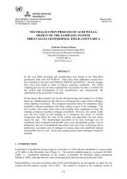
12••• ••••o:/.4"m :() Known oreos of klw tniltlwity...-.. ~ ~.)'lIjonn Pnlsuto~ ""INC zone• HiQh t."'*"'ture enc.,- Ma<strong>in</strong> tectonic iaJ"- Eruption '''tuNS•Fig. 1 Western Reykjanes pen<strong>in</strong>sula <strong>and</strong> l ocation of Svarts eng! high <strong>temperature</strong> field (from Franzson. 1983).horizontal planes) are used 1n <strong>the</strong> study of <strong>the</strong> behaviourof <strong>the</strong> reservoir as a function of time. Boil<strong>in</strong>g conditionsas a function of time are also <strong>in</strong>cluded .1.3 Geographical sett<strong>in</strong>g of SvartsenglThe Mid-Atlantic Ridge surfaces on to Icel<strong>and</strong> at <strong>the</strong>southwestern end of <strong>the</strong> Reykjanes pen<strong>in</strong>sula where itcrosses <strong>the</strong> country <strong>in</strong> a nor<strong>the</strong>asterly direction. The riftprocess on thE: Reykjd lles pen<strong>in</strong>su l a Is characterized by anENE-WSW trendlng seismic zone below 2-3 km depth, but on<strong>the</strong> surface by NE - SW fissure swarms arranged en echeleon
1 3to <strong>the</strong> former (Georgsson. 1981; Franzsson, 1983).<strong>in</strong>tersection of <strong>the</strong> two types is <strong>the</strong> Svartsengi<strong>temperature</strong> field located (Fig. 1).Atanhigh-1.4 Data used <strong>in</strong> <strong>the</strong> reportThe <strong>temperature</strong> <strong>and</strong> <strong>pressure</strong> measurements used In thisstudy were all taken by <strong>the</strong> Geo<strong>the</strong>rmal Division of <strong>the</strong> NEA<strong>in</strong> <strong>the</strong> period between '16.07.12 <strong>and</strong> '83.06.16. Thedifferences In <strong>the</strong> well conditions at <strong>the</strong> time of measure ment range from <strong>the</strong> wells hav<strong>in</strong>g been closed for as longas one year I up to measurements made right after production.1.5 Limits to <strong>the</strong> studyThe work Is restricted to <strong>the</strong> time <strong>and</strong> spatial distributionof <strong>temperature</strong> <strong>and</strong> <strong>pressure</strong> at depths of 500 m <strong>and</strong> below<strong>in</strong> <strong>the</strong> Svartsengl reservoir.
1 42 GENERAL DESCRIPTION OF THE FIELDLocation of wells, faults <strong>and</strong> dikes <strong>in</strong> <strong>the</strong> Svartsengl fieldIs shown <strong>in</strong> Fig. 2 . The Svartsengi high-<strong>temperature</strong> area 1nIcel<strong>and</strong> is a part of <strong>the</strong> Reykjanes geo<strong>the</strong>rmal system. Thegeo<strong>the</strong>rmal wells at Svartsengi yield 235°C water <strong>in</strong> 1983which Is 5°C less than <strong>the</strong> 240°C before production began.The sal<strong>in</strong>ity Is roughly two - thirds that of sea water(Thorhallsson, 1979) .2.1 Geological sett<strong>in</strong>gThe geological succession of <strong>the</strong> field consists of lavasuccess ions wit h <strong>in</strong>terven<strong>in</strong>g hyaloclastlte formations(Franzsson, 1983) . Some 20 - 40 % of <strong>the</strong> succession below800 ID depth consists of <strong>in</strong>trusions . The reservoir acquifersare predom<strong>in</strong>antly controlled by <strong>in</strong>trusives <strong>and</strong> sometectonic fractures/faults. The alteration pattern can besubdivided <strong>in</strong>to dist<strong>in</strong>ct episodes where low <strong>temperature</strong>conditions are seen to have prevailed prior to high<strong>temperature</strong>conditions. Two dist<strong>in</strong>ct episodes of h1gh<strong>temperature</strong>activity are observed, where <strong>the</strong> latter onerises separately to higher elevation. The dom<strong>in</strong>ant alterationpattern conforms reasonably well to <strong>the</strong> present<strong>the</strong>rmal regime <strong>in</strong> <strong>the</strong> field (Franzsson, 1983 ) .2.2 Chemical studiesChemical analysis of <strong>the</strong> geo<strong>the</strong>rmal water <strong>in</strong>dicates about67 % sea water, but deuterium measurements give only about57 % sea water (Arnason, 1976). The difference isexpla<strong>in</strong>ed by flash<strong>in</strong>g of <strong>the</strong> water <strong>in</strong> <strong>the</strong> conceptual modelof Kj aran et 01.(1979). It 1s assumed that <strong>the</strong> rechargearea for <strong>the</strong> geo<strong>the</strong>rmal water is located <strong>in</strong> <strong>the</strong> vic<strong>in</strong>ityof lake Kleifarvatn.
u JHD - BJ~2300 HF,83.05.0702 AAI>-Y""'~ L<strong>in</strong>e of section11fIrS-12 S-IO 1/It11S-2 11/ Concealed fault",/ 40 fhraw <strong>in</strong> meters1 J •• ~S-3/" Concealed dyke, J/1• S -9 aorehole-1 •, 11110 100 200 300m7, , 11J/I 1I!11I111111tNIII \t I"/" S-5 --::;I>- S-7 \\, ~f:. -- :=t"'-=---- ! 1di/f/40;8011,\ "'-- _-;:"""111IJ11""" - :::-- I'IS-8S- I /I/It /- f -J/40f / rI101I1 /"S-IIrI-; 11J//25)11'11111/1111Fig. 2 Location of wells. faults a nd dykes <strong>in</strong> <strong>the</strong> Svartsengiproduction field (from Franzson, 1983).
1 6~JHD-8 J - Z300 Hr.L'J:J 8 ~~0703 AAADepth[m)5009 11 7 8 4 5 6 12 :3 2100'-~----++---+4-~-+--~~~BI u"'"u'">-" t.J>,,'"!.J>....'" ::>"....z1000t 11 H1500\-rM ,'"~" .... -,,~;~"" ..... ,>,,'" ~:,'I;.... ''''-' /i:, ,I'-.!.--I!, ," :, " \' ,, -, -, '" ,~,
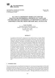
1 72.3 Resistivity studies of <strong>the</strong> fieldSurface hydro<strong>the</strong>rmal manifestations are meager with<strong>in</strong> <strong>the</strong>Svartsengi field <strong>and</strong> only scattered over about 4 squarekl1ometers. The resistivity surveys (Fig. 4) show <strong>the</strong>geo<strong>the</strong>rmal area to be elongated NE - SW 1n <strong>the</strong> nor<strong>the</strong>rn partbut ESE-WSW <strong>in</strong> <strong>the</strong> sou<strong>the</strong>rn part (Georgsson, 1981), Acont<strong>in</strong>uous E- W strik<strong>in</strong>g low resistivity zone whichco<strong>in</strong>cides fairly closely wi th <strong>the</strong> Reykjanes seismic zonetha t has been <strong>in</strong>terpreted as a plate boundary. Study ofcorrelation between resistivity sal<strong>in</strong>ity <strong>and</strong> <strong>temperature</strong>seem to confirm that <strong>the</strong> low resistivity can only beexpla<strong>in</strong>ed by anomalously high heat flow . This <strong>in</strong>dicatesthat explol table geo<strong>the</strong>rmal energy may be found 1n <strong>the</strong>uppermost 1 - 2 km along <strong>the</strong> plate boundaries on <strong>the</strong>Reykjanes Pen<strong>in</strong>sula even far away from surface manifestations.2.~ TectoniC activity of <strong>the</strong> Reykjanes pen<strong>in</strong>sulaOne can see <strong>the</strong> ma<strong>in</strong> zone of earthquakes <strong>and</strong> location ofquake epicenters on <strong>the</strong> area from Fig. 1. The tectonicactivity <strong>in</strong>creases <strong>the</strong> permeability <strong>and</strong> thus creates somesort of a dra<strong>in</strong>age system along <strong>the</strong> zone of earthquakes.Some geo<strong>the</strong>rmal areas like Svartsengi are situated wheresurface fissure swarms <strong>in</strong>tersect <strong>the</strong> ma<strong>in</strong> zone of earthquakes.2.5 Hydrological characteristics of <strong>the</strong> geo<strong>the</strong>rma l systemThe water percolates down from <strong>the</strong> <strong>in</strong>filtration area <strong>and</strong>flows along <strong>the</strong> permeable earthquake zone. On its way itwarms up <strong>and</strong> mixes with <strong>in</strong>trusive seawater. Where <strong>the</strong>surface fissure swarms <strong>in</strong>tersect <strong>the</strong> earthquake zone. <strong>the</strong>permeability becomes great enough to allow free convection,thus form<strong>in</strong>g a geo<strong>the</strong>rmal area.
c:J~5nmc::J5-anm5- L<strong>in</strong>es, of equcl..... resishviliso..... ........... , ....... .~::::::3 ~ a.12 mHiQh tempercture fieldoooo, ,le or"~REYKJANES PENINSULARES I STIVITY AT 600 M.A.S.LFig. 4 Resistivity at 600 m depth below sea level at <strong>the</strong>western part of <strong>the</strong> Reykjanes pen<strong>in</strong>sula(from Georgsson et al., 1983) .
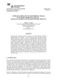
1 9Fresh water is pumped from shallow wells at a distance of 4to 5 km from <strong>the</strong> plant. There Is a fresh water lens ofonly 45 m thickness <strong>in</strong> porous surface lavas. The lens IsfloatIng on top of <strong>the</strong> seawater below. The pump<strong>in</strong>g is donewith great care <strong>in</strong> order to avoid pump<strong>in</strong>g "salt ll waterwhich could happen if <strong>the</strong> drawdown of <strong>the</strong> fresh watersurface <strong>in</strong> <strong>the</strong> well Is too much .2.6 Proposed reservoir model by Kjaran et al. (1979)This conceptual model for <strong>the</strong> regIonal geo<strong>the</strong>rmal system isa hybrid convection model for <strong>the</strong> geo<strong>the</strong>rma! area itselfl<strong>in</strong>k<strong>in</strong>g toge<strong>the</strong>r reservoir performance <strong>and</strong> well performanceto give an estimate of <strong>the</strong> reservoir capacity.Free convection exists to some extent <strong>in</strong> most geo<strong>the</strong>rmalreservoirs (Ellasson, 1973). <strong>in</strong>creas<strong>in</strong>g considerably <strong>the</strong>normal heat flow to <strong>the</strong> surface. The heat flux has topenetrate <strong>the</strong> caprock <strong>and</strong> it can be shown that it is almostimpossible that heat transport be only by conduction.There has to be some heat trans port by discharge of hotwater <strong>and</strong> steam to keep <strong>the</strong> convection go<strong>in</strong>g. If <strong>the</strong>re issuch an outflow from <strong>the</strong> reservoir it must be expected tobe balanced by an equal amount of <strong>in</strong>flow . This <strong>in</strong>flow isassumed to be <strong>the</strong> <strong>in</strong>filtration at lake Kleifarvatn,flow<strong>in</strong>g along <strong>the</strong> ma<strong>in</strong> earthquake zone, as shown <strong>in</strong> Fig. 5.The recharge <strong>and</strong> discharge flow <strong>and</strong> <strong>the</strong> convection are <strong>the</strong>premise for <strong>the</strong> hybrid convection model shown <strong>in</strong> Fig. 5.From this figure one can wr i tethree cont<strong>in</strong>uity equations at eachequations are: cont<strong>in</strong>uity of mass,down six e quat ions:po<strong>in</strong>t E <strong>and</strong> D. Theenthalpy <strong>and</strong> chlorideconcentration. There are six equations <strong>and</strong> twelve unknowns.So six unknowns have to be assumed. At Svartsengi <strong>the</strong>separameters were ei<strong>the</strong>r measured or estimated thus enabl<strong>in</strong>g<strong>the</strong> authors to solve for <strong>the</strong> rema<strong>in</strong><strong>in</strong>g unknowns. Thenatural heat loss can <strong>the</strong>n be calculated as <strong>the</strong> differenceof <strong>the</strong> upward <strong>and</strong> downward heat flow. The calculated valuewas about 300 MW, which was three times <strong>the</strong> necessary power
;-n va o-vv ~ 900 . S.P".KL.l:=J 82 .010037 Sy .J'" oA 1140 m osl1 SvortsengiPA~IOOO kg/m'uK A = 0 .2.10 - 5 m/sec- - -COi~-sea waTer - - - - -( d22?222?lP~'" "Ill"~ qt??cc?> \.\KB -2000 2,5U"0.3'10-'m/ secPB~ 190kp/cm 2 P B ~835 kg/m'BJ. J. X A --7 :z A' A X -Xr--CoTemp.'c500 601000 1201500 1802000 2402500 300Pressurekp/cm250.610014619022882.0 1. 003 7.Layer 3k-oFig. 5 Conceptual flow model from <strong>the</strong> Reykjanes pen<strong>in</strong>sula(from Kjaran et al., 1980).
... T [IIKFII€9ISlOFoVI VII2.O
22consumption of <strong>the</strong> geo<strong>the</strong>rmal heat <strong>in</strong>g plant. Fig . 6 shows<strong>the</strong> discharge of wells <strong>and</strong> drawdown <strong>in</strong> <strong>the</strong> Svartsengireservoir from 1976 to 1982.2.7 General <strong>temperature</strong> conditionsThe general <strong>temperature</strong> picture of <strong>the</strong> field is describedby Fig. 7. There is a 300 m layer of warm water systemhav<strong>in</strong>g a <strong>temperature</strong> of 1I0-60 D C which can be seen frommeasurements of wells which water level Is 15-20 m belowground level. The geo<strong>the</strong>rrnal system between <strong>the</strong> depths of600 m <strong>and</strong> 2000 m had a <strong>temperature</strong> of at least 240°C when<strong>the</strong> undisturbed water level was between 64 <strong>and</strong> 73 m before1976. In o<strong>the</strong>r words <strong>the</strong> warm water system overlies <strong>the</strong>geo<strong>the</strong>rmal system at all locations except <strong>in</strong> <strong>the</strong> westernpart of <strong>the</strong> field (Wells SG-2, 3 <strong>and</strong> 10) where <strong>the</strong> latteris vented to <strong>the</strong> atmosphere through fumaroles. There <strong>the</strong>subsurface <strong>temperature</strong> follows <strong>the</strong> boil<strong>in</strong>g po<strong>in</strong>t curve downto ~OO-500 m where a <strong>temperature</strong> of about 2~OoC is reached.2.8 The power plantThe power plant at Svartsengi is <strong>the</strong> first geo<strong>the</strong>rmal plantof its k<strong>in</strong>d <strong>in</strong> <strong>the</strong> world (T horhallsson, 1979). The th<strong>in</strong>gthat makes it unique is that a high <strong>temperature</strong> br<strong>in</strong>e isused as a heat source for space heat<strong>in</strong>g <strong>and</strong> also for <strong>the</strong>generation of electricity. called co-generation. thusmak<strong>in</strong>g better use of <strong>the</strong> geo<strong>the</strong>rmal energy than isord<strong>in</strong>ary for high-<strong>temperature</strong> geo<strong>the</strong>rmal <strong>in</strong>stallations.This plant was constructed <strong>in</strong> several stages. The geo<strong>the</strong>rmalfluid is exploited by us<strong>in</strong>g heat exchangers for<strong>the</strong> space heat<strong>in</strong>g of all <strong>the</strong> communities <strong>in</strong> <strong>the</strong> westernReykjanes pen<strong>in</strong>sula <strong>and</strong> <strong>the</strong> <strong>in</strong>ternational airport atKeflavik (Thorhallsson. 1979). It was first built togenerate 50 MWt (megawatt <strong>the</strong>rmal) <strong>and</strong> 2 MWe (megawattelectric) for a district heat<strong>in</strong>g system. A 75 MWt a nd 6 MWeaddition was later completed. The heat is extracted byflash<strong>in</strong>g <strong>the</strong> br<strong>in</strong>e <strong>in</strong> two stages to60 0 c <strong>and</strong> us<strong>in</strong>g <strong>the</strong>
2 3~ JHO-HSP - 2300 G9~ 83.091236 AADepth[m]250SIMPLIFIED TEMPERATURE PROFILE OFTHE SVARTSENGI GEOTHERMAL FIELDo 100 200 300 [OCJo+--.--~----~----~~~----------~Warm water systemTemperature 40-60°CWater level <strong>in</strong> wells15 -20 m below ground leve I5007501000-1250-The geo<strong>the</strong>rmal systembelow 600 m de plhTemperature co. 240°CUndisturbed water level01 64-73 m deplhbefore 1976150017502000Fig. 7 Simplified <strong>temperature</strong> profile of <strong>the</strong> Svartsengigeo<strong>the</strong>rmal field.
flash steam for heat <strong>and</strong> electricity generation. The pilotplant studies were <strong>the</strong> basis for <strong>the</strong> design of <strong>the</strong> firststages <strong>in</strong> construct<strong>in</strong>g <strong>the</strong> plant Never<strong>the</strong>less a lot ofdetails. materials <strong>and</strong> components had to be tested before<strong>the</strong> ma<strong>in</strong> plant was designed <strong>and</strong> constructed. All <strong>the</strong> same<strong>the</strong> power plant has been able to supply <strong>the</strong>rmal energy to<strong>the</strong> different communities accord<strong>in</strong>g to <strong>the</strong> requirement atany time s<strong>in</strong>ce <strong>the</strong> commencement of <strong>the</strong> programme.2.9 History of developmentThe highlights of <strong>the</strong> historical development of t he projectare as follows (Bjornsson. 1983):1971 - 1972 Wells SG-2 <strong>and</strong> SG - 3 were drilled to depths of 240<strong>and</strong> 400 m respectively. The results turned out to be veryencourag<strong>in</strong>g prov<strong>in</strong>g <strong>the</strong>re was a high <strong>temperature</strong> fieldwith a br<strong>in</strong>e <strong>temperature</strong> of 235°C.1974 The <strong>Orkustofnun</strong> (NEA) built aSvartsengi. Two wells weredrilled. SG-4pilot plant at(1700 m) <strong>and</strong> SO-5(1525 m).1974-1975 Tests were carried out by <strong>the</strong> <strong>Orkustofnun</strong> (NEA)<strong>in</strong> <strong>the</strong> pilot plant which later became <strong>the</strong> basis for <strong>the</strong>design of power plant 1.1976 Prelim<strong>in</strong>ary power plant of 3 MWt was commissioned onNovember 6.1977 First unit of power plant 1 of 8 MWt was commissioned<strong>in</strong> November.1978 First 1 MWe turbogenerator was commissioned <strong>in</strong> April.Second unit of power plant 1 of 12.5 MWt was c ommissioned<strong>in</strong> November. Well SG-6 was drilled to a depth of 1734 m.1979 Third <strong>and</strong> fourth units of power plant of 2 X 12.5MWt were commissioned. The second 1 MWe turbogenerator was
25commissioned. Well SG - 7 was drilled to a depth of 1438 m.1980 Third 6 MWe t urbogenerator was commissioned. WellsSG - 8, SG-9, SG-l0, <strong>and</strong> SC - 1t were drilled to depths of1603, 994, 425 <strong>and</strong> 1'41 m respectively.1981 First unit of power plant 2 of 25 MWt was commisioned<strong>in</strong> May. Second <strong>and</strong> third units of power plant 2 of 2 X 25MWt were commissioned 1n September.1982 The tota l <strong>in</strong>stalled capacity <strong>in</strong> power plants 1 , 2 <strong>and</strong>3 became about 46 MWt • 2 MWe, 75 MWt <strong>and</strong> 6 MWerespectively. The last well to date, namely SG-12 wasdrilled to a depth of 1488 m. Relnjection was done for 25days <strong>in</strong> <strong>the</strong> months of September <strong>and</strong> October.
263 INSTRUMENTATIONThe Amerada mechani caI gauges were used for both tempera ture <strong>and</strong> <strong>pressure</strong> measurements used <strong>in</strong> this researchproj ect.There are two ma<strong>in</strong> types of mechanical gauges, namely <strong>the</strong>Amerada <strong>temperature</strong> gauge, which has a bourdon tube where<strong>the</strong> boil<strong>in</strong>g <strong>pressure</strong> of a special fluid Is recorded, <strong>and</strong><strong>the</strong> Kuster gauge which has a bimetal sensor where <strong>the</strong><strong>temperature</strong> torsion of <strong>the</strong> bimetal <strong>in</strong>dicates <strong>the</strong> tempera -ture. When us<strong>in</strong>g <strong>the</strong> mechanical gauges data Is nottransmitted to <strong>the</strong> surface, but is recorded <strong>in</strong>side <strong>the</strong>probe on a clock driven recorder. As many as 20 - 30measur<strong>in</strong>gwell.pO<strong>in</strong>ts can be recorded dur<strong>in</strong>g one run 1n <strong>the</strong>The Amerada gauges consist of three basic parts, <strong>the</strong>record<strong>in</strong>g section, a clock <strong>and</strong> ei<strong>the</strong>r a <strong>pressure</strong> sensor ora <strong>temperature</strong> sensor (Figures 8 <strong>and</strong> 9).3.1 Pressure elementThe active element <strong>in</strong> <strong>the</strong> <strong>pressure</strong> element i s a helicalbourdon tube, fixed at one end <strong>and</strong> free to rotate at <strong>the</strong>o t her. The <strong>in</strong>terior of <strong>the</strong> tube is subjected or exposed to<strong>the</strong> <strong>pressure</strong> <strong>in</strong> <strong>the</strong> well. The result<strong>in</strong>g rotation of <strong>the</strong>free end of <strong>the</strong> bourdon tube is transmitted directly to arecord<strong>in</strong>g stylus without <strong>the</strong> use of gears or levers. Thestylus records on a metal chart made of th<strong>in</strong> metal coatedon one side with a special pa<strong>in</strong>t. The pa<strong>in</strong>t rendersfriction extremely low <strong>and</strong> <strong>the</strong> scribed l<strong>in</strong>es are so easilyvisible that <strong>the</strong> chart scanner user can measure chartdeflections to obta<strong>in</strong> <strong>the</strong> accuracy <strong>the</strong> gauge is capable ofproduc<strong>in</strong>g. The chart is carried on a removable cyl<strong>in</strong>dricalchart holder, <strong>the</strong> position of which is controlled by aclock.
27~ J H D-HS~ - 9 0 00 Gl:iL.J::..J 83 .09. 12 42Clock I, . ,WIRELINESO CKETCOMPLETERECORDINGPRESSUREReeord1naSecti onti ,Ireadscrew:'Chart:Ho lderf,StylusAssemblyOUTERHOUS I NGGAUGEPr" ssureElementTEMPERATUREELEMENTMax.Read<strong>in</strong>gTherm.011TrapThe rm.WellBOTTOM HOLE RECORDINGPRESSURE OR TEMPERATURE GAUGERPG-3 1 1,;" Dia . RPG-4 1" Dia.~lg.8 Amerada record<strong>in</strong>g gauges for <strong>pressure</strong> <strong>and</strong>tempera t ure.
;T=1 JHD·HS~·9000 GGL.:J::J 83 .09.1241OutlrHoul<strong>in</strong>, ----0Support,..St'l'IUI ___ _BULBSund.rdFnl R.spond <strong>in</strong>lTEMPERATUREELEMENTClrry<strong>in</strong>,M" dmumR.,illlrln,ThlrmomltlrRECOROING SECTION(GAUGE)PRESSUREELEMENTFig . 9 Cross-sections of Amerada <strong>pressure</strong> <strong>and</strong> t emperatureprobes.
293.2 Temperature elementThe bourdon tube <strong>in</strong> <strong>the</strong> <strong>temperature</strong> element is sealed.Variations 1n <strong>temperature</strong> create different boil<strong>in</strong>g<strong>pressure</strong> <strong>in</strong>side <strong>the</strong> bourdon tube. The vapour <strong>pressure</strong> of<strong>the</strong> enclosed liquid is directly related to its <strong>temperature</strong>,mak<strong>in</strong>g <strong>the</strong> rotated position of <strong>the</strong> free end of <strong>the</strong> bourdontube an usable measure of <strong>the</strong> <strong>temperature</strong> of <strong>the</strong> element.This rotation is recorded on <strong>the</strong> gauge chart as describedabove.3.3 Limits of accuracyThe repeatabl11ty of a properly ma<strong>in</strong>ta<strong>in</strong>ed gauge is betterthan -0.1 % of full range of <strong>the</strong> <strong>pressure</strong> element <strong>in</strong> use,while <strong>the</strong> absolute accuracy Is 0 . 2% . Temperatures above70 0 C affect <strong>the</strong> strength of most Bourdon tubes socalibrations are necessary to ma<strong>in</strong>ta<strong>in</strong> <strong>the</strong> accuracy of <strong>the</strong><strong>in</strong>strument. The sensitivity of <strong>the</strong> gauge 1s 0.2% of fullscale deflection.The absolute accuracy of <strong>the</strong> <strong>temperature</strong> gauge is usuallyassumed to be 2°C but this is related to <strong>the</strong> calibration<strong>and</strong> operation of <strong>the</strong> <strong>in</strong>struments.
304 INDIVIDUAL WELLSThere have been drilled 12 wells In <strong>the</strong> high <strong>temperature</strong>field of Svartsengi (Fig. 2). The <strong>temperature</strong> changes withrespect to time <strong>and</strong> <strong>the</strong> boil<strong>in</strong>g conditions are discussedIn this chapter.Well SG -l Is a shallow well with relatively low tempera ture. It was drilled for <strong>the</strong> purpose of us<strong>in</strong>g its water Indrill<strong>in</strong>g <strong>the</strong> o<strong>the</strong>r wells. The depth of <strong>the</strong> well Is 250 m<strong>and</strong> <strong>the</strong> <strong>temperature</strong> is less than 50°C. A peak <strong>in</strong> tempera -ture Is measured at <strong>the</strong> ground water level of 25 m depth(Fig. 10). This <strong>in</strong>dicates a considerable horizontal flowIn this shallow acquirer, most probably a run off from <strong>the</strong>ma<strong>in</strong> geo<strong>the</strong>rmal field (Stefansson <strong>and</strong> Stelngrimsson.1981). The maximum <strong>temperature</strong> measured In this well is47°C at <strong>the</strong> bottom at 250 m depth. The <strong>temperature</strong> at thisdepth <strong>in</strong> <strong>the</strong> nearest well (SG-5) is about 200°C, show<strong>in</strong>g<strong>the</strong> abrupt demarcation of <strong>the</strong> geo<strong>the</strong>rmal system at thislocation <strong>and</strong> depth. The cold ground water reaches down tolittle more than 200 m depth, but beneath that <strong>the</strong> <strong>temperature</strong><strong>in</strong>creases more steeply, which might be a sign that ahotter fluid can be found at greater depth at thislocation.The <strong>pressure</strong> gradient <strong>in</strong> <strong>the</strong> well is hydrostatic (~ig. 11)correspond<strong>in</strong>g to a mean density of 1022 kg/~. The densityof seawater at 35°C is 1021 kg/m 3 .Well SG-2 is a shallow well (about 250 m deep) located <strong>in</strong><strong>the</strong> area where <strong>the</strong> geo<strong>the</strong>rmal system is vented to <strong>the</strong>atmosphere. It was <strong>in</strong>itially boil<strong>in</strong>g up to at least 115 m.Now It Is boil<strong>in</strong>g from top to bottom. Unlike many o<strong>the</strong>rwells of<strong>in</strong>creasedresult of<strong>the</strong> Svartsengi geo<strong>the</strong>rmal field, this well has<strong>in</strong> <strong>temperature</strong> with time (~ig. 12). This is <strong>the</strong><strong>in</strong>creased boil<strong>in</strong>g In <strong>the</strong> top of <strong>the</strong> reservoirdue to <strong>the</strong> <strong>pressure</strong> drawdown In <strong>the</strong> reservoir. The boil<strong>in</strong>glevel Is cont<strong>in</strong>uously migrat<strong>in</strong>g to larger depths, whichresults In higher <strong>pressure</strong> <strong>and</strong> <strong>temperature</strong> of <strong>the</strong> steamcap <strong>in</strong> <strong>the</strong> top of <strong>the</strong> system. Between 1976 <strong>and</strong> 1981 <strong>the</strong>
SVARTSENG I ,WEL L SG-1SVAR TSENG IWEL L 8G- 1TEMPER ATURE Le]31 ~ ~ 3~ ~ ~ D ~ ~ ~ 41 .2 43 4 4 ~ ~ Uo I I , , , , , , , , , , , ! ! t I•, •PRESSURE (kg/cnl'J8 10 12 14 1(1 18 20 22 24""~"""."'"n,urW0'",~'"".'"n,urrw0'"'"'"'"'",~'"_I'EASURED ' 76.07 . 17 8.S.'00 "J__ i--L-" __ i--L-" __ i--L-" __ i--L-" __ i--L-" __ L'"'"-+-MEASURED ' 111.01.17 S.S .,"J-
32~~• ..~, .J ..3 • w_ o"- • •Cl)~ 0", • , ·00 • >0• •0 0 c.;;- 0~ ~~•N, ,. , .... -,--.--......- , I ...... -.......•0 00 .•~ ~ , ,• •0("'J Hlrl30< < "•• •I I • c0 0~ ,N 0• • • • •~• •~~ ---'.• c• •~N--- -_..;;~1; ~~c] •• 00 •, •, •~ • •~~e. • c- N • "(!) I 0•• 0Z(!) w.0WCI)Cl) •• " 28 -- •~~ • ,f-..J 00N- O00~..:--c00"" •0 0 < ~ ~ • • • • •0
33<strong>temperature</strong> at <strong>the</strong> bottom of <strong>the</strong> well has <strong>in</strong>creased by 15°C(Fig. 12), <strong>and</strong> <strong>the</strong> correspond<strong>in</strong>g <strong>pressure</strong> <strong>in</strong>crease is 1.3bar (Fig. 13).Well SG-3 Is located close to well SG-2. It is ~02 m deep<strong>and</strong> has a bottom <strong>temperature</strong> of about 225°C as measured In177.06.14. At that time, a two-phase zone reached up toapproximately a depth of 250 m (see Fig. 15). In 1981 <strong>the</strong>boil<strong>in</strong>g level has migrated down to 375 m (FIg. 15) <strong>and</strong> <strong>the</strong><strong>temperature</strong> has decreased by about 15°C. Fur<strong>the</strong>r drawdownIn <strong>the</strong> reservoir has resulted <strong>in</strong> a pure steam cap down to<strong>the</strong> bottom of <strong>the</strong> well. Both <strong>temperature</strong> <strong>and</strong> <strong>pressure</strong> have<strong>in</strong>creased <strong>in</strong> <strong>the</strong> period from 1981 to 1983 as can be seen <strong>in</strong>Fig. 14 <strong>and</strong> 15.Well SG - 4 was <strong>in</strong>itially drilled to 1713 m depth, <strong>and</strong> for along time it was a production well with 1680 m cleardepth. Cas<strong>in</strong>g damage occured <strong>in</strong> <strong>the</strong> well <strong>in</strong> 1980 <strong>and</strong> <strong>the</strong>attempt of repair<strong>in</strong>g it by redrill<strong>in</strong>g was unsuccessful. Thedrill bit went out of <strong>the</strong> cas<strong>in</strong>g. Presently <strong>the</strong> well isopen to 540 m depth <strong>and</strong> cannot be utilized for powerproduction. The top of <strong>the</strong> geo<strong>the</strong>rmal system is fairlywell def<strong>in</strong>ed by <strong>the</strong> <strong>temperature</strong> profiles <strong>in</strong> <strong>the</strong> well(Fig. 16). The steep <strong>temperature</strong> <strong>in</strong>crease between 400 m<strong>and</strong> 600 m reflects <strong>the</strong> impermeable layer at <strong>the</strong> top of <strong>the</strong>reservoir at this depth. The <strong>in</strong>itial <strong>temperature</strong> <strong>in</strong> thiswell was close to 240°C <strong>and</strong> <strong>the</strong> <strong>temperature</strong> was ra<strong>the</strong>runiform at least down to 1700 m depth. The <strong>pressure</strong>gradient is hydrostatic <strong>and</strong> boil<strong>in</strong>g conditions have notbeen observed <strong>in</strong> <strong>the</strong> well dur<strong>in</strong>g static conditions(Fig.17).Well SG-5 is 1519 m deep. There has been a <strong>temperature</strong>change of 3°C deep <strong>in</strong> <strong>the</strong> well. The <strong>pressure</strong> drawdownbetween <strong>the</strong> years 1976 <strong>and</strong> 1983 has been about 13 kg/cm3(Fig. 21). Boil<strong>in</strong>g levels were at 300 <strong>and</strong> at 400 rn <strong>in</strong> <strong>the</strong>years 1982 <strong>and</strong> 1983 respectively (Fig. 19 <strong>and</strong> 20). whereasno boil<strong>in</strong>g is recorded <strong>in</strong> 1976 (Fig . 18).
~. - .34•~~, ~~g0•~/N, •INI ,• I j 0N• • N,&;.• -c') ON /b ,to I , . ,ON• Zto~~ I, W(I) (I) •W->- ..J ~N/ C>: ..J ,. ,• •~~N , ~ i ,«W ~.>3 w_ , • • •(I)~","-/ • • ~,- "~8 8N ~~: • >~• '"~• -" , ~~0 0•0w w w• ~~ ~ ·0•, r • • ~ ~ •> ~~I I I" ,'Trnot..- ,......,-.- · ~T""' - i, ..-rp~~"• •0~ ~ 8 • • g • ~ g0~ g0 0N N• ,N N N 0- - - - , • • •~N N" • " • • •~CW) Hld3C1;r..~,~~L.....u......l. .........L...o......L..o ~!" "/,//0., "; • •~0• , ,•0i1, - ----0,.-" ,• " ;: · • • •J·-.- •• ,"'• ,~ • ·,-C) [Lj ,:i .; j, N0 to I L -0 N / ...- • ~" ,Zto w , , ;;j•~,W(I) 0~~ •w .,(I)~ ~ •,•>-..J : ..J ~2 • • • • J~ ~ ~~!! w «W"• • 3 w. • , (I) , ~ - • , ~ ~ ~ • •0• " 00, !" ! 0 >••• ~ ~ ;; ,§..; ..; 1 • >• 0u u 1 •0 0~ u w • • ~J, ~ > >~ ~ , •0 ~~ • • • ui •~ • ~ • ·I• I • • I I ," •>• -~~ 0~ : I 1 ...... ' , ,,, , " •0 0 0• ~ • • ~ ~ • ~ • g 0 00 ,0 N •~,N N N• • • • •N, , "[W] Hld30• •~•~
-".(!)'W (!)rJ)rJ)fa...J WrJ) 3-".(!) ,Z(!)WrJ)rJ)f-...Ja...J3rJ)G~u"~~ ,
SVARTSENGIWELL SG-5TEMPERATURE CC)85 IOI!§ '26 He 1&6 186 20& 225 24& 28 5 2815 306 3215o j , , , , , , , , ! 1 , l'"."'"SVART8 ENGIWELL 8G-5TEMPERATURE ["C)1110 170 liD 190 200 2 10 220 230 2
SVARTSENGIWELL SG-5SVARTSENGIWELL SG-5n,uTEMPER" TURE le]190 200 210 220 230 2~O 260 2eO 270 280 290 300 310o I ! I 1 , I , , , , , ! I'"'"'"'"i=.ooo•~,~.."'""''''_I1EASUREO '83. 06.05 es_ S.9.T. ACC. lO tEAS. PRESSUA[ '83 .01l .. 0S liS",,-L~-L~-L"-"-"-"-"-"-"-L-~~~-"-"-"-"~-"~-LFlg. 20 Svart~engl well se-s . Temperature prorlle In 1983<strong>and</strong> correspond<strong>in</strong>g saturation prorlle.,'"'"'"."'"'"'"."n,u .";: t 000• w01100,~"",...'""'""1100,~,""''''''PRESSURE (kg/c..n12 ~ ~ ~ ~4 ~ 80 9 n ~ ~ 100 I~ \10j , , , , , , , , , , , , l_ MU_EO ' 83 .011.05 BS_MEASUAEC '12.03 . 1' 119/ 81>9' P_t3. 1 bQ ~_IIEA!UAEO '7t1.07. 17 8 .S, • II.!.. 14. 4 .JL-"-,-"-,-"-",-__ ,-"-"-__ -,-"-,-"-"-""-,-,-,-"--, .. Iflg.21 SVllrtsengl IIell SG-5 . Pre.ssur e p r o rlles In 1976 ,1982 <strong>and</strong> 1983 . ...•w...,
38Wel l SG - 6 was 1731i ID deep before it was redrilled <strong>in</strong> 1982to a depth of 19511 rn. Apparent changes <strong>in</strong> <strong>temperature</strong>profiles <strong>in</strong> 1982 are due to <strong>the</strong> cool<strong>in</strong>g effect of thisredrill<strong>in</strong>g. The cool<strong>in</strong>g effects are <strong>the</strong>refore badlydocumented <strong>in</strong> this well. Deep In <strong>the</strong> well it has cooleddown by !j°C between <strong>the</strong> measurements of '81.12.09 <strong>and</strong>'83.06.15 (Fig. 22). In <strong>the</strong> same period <strong>the</strong>re has been a<strong>pressure</strong> drawdown of about 4 k g/cm2 (Fig. 23). In 1983 <strong>the</strong>boil<strong>in</strong>g level has gone deeper than 500 m.Well SG - 7 is 1438 ID deep. There has occured a cool<strong>in</strong>g ofabout SOC (Fig . 25) <strong>and</strong> a <strong>pressure</strong> drawdown of 3 kg/cm2between <strong>the</strong> '82.03.15 <strong>and</strong> '83.05.04 measurements(Fig. 26). But between <strong>the</strong> ' 80.10 . 08 <strong>and</strong> '83.05 . 04 datedmeasurements <strong>the</strong>re has been a cool<strong>in</strong>g of 4 to 7°C (Fig. 24)<strong>and</strong> a <strong>pressure</strong> drawdown of 7 kg/cm2 (Fig . 26). In 1980,1982 <strong>and</strong> 1983 <strong>the</strong> boil<strong>in</strong>g levels were at 400, 450 <strong>and</strong> 500m respectively (Fig. 25) .Well SG-8 has a depth of 1603 m <strong>and</strong> has undergone a changeof 7°C cool<strong>in</strong>g (Fig. 27) <strong>and</strong> a <strong>pressure</strong> drawdown of2 kg/cm2 between <strong>the</strong> measurements dated '82.03.16 <strong>and</strong>'83.03.16 (Fig. 28). Accord<strong>in</strong>g to <strong>the</strong> measured <strong>pressure</strong> on<strong>the</strong>se dates <strong>the</strong> boil<strong>in</strong>g level was 425 <strong>and</strong> 450 mrespectively (Fig. 27).Well SG - 9, which is 994 m deep , experienced a cool<strong>in</strong>g of9°C at depth (Fig. 29) with a <strong>pressure</strong> drawdown of2 kg/cm2 between '82 . 03.17 <strong>and</strong> '83.05.04 (Fig. 30). At <strong>the</strong>latter date it was boi l <strong>in</strong>g at a level of about !l50 mwhereas <strong>the</strong>re is no <strong>in</strong>dication of a ny boil<strong>in</strong>g at<strong>the</strong> formerdate.Well SG - l0 is 425 m deep <strong>and</strong> close to wells SG - 2 <strong>and</strong> SG - 3.At this location, <strong>the</strong> reservpoir is boil<strong>in</strong>g down to <strong>the</strong>bottom of <strong>the</strong> well. The steam cap is down to !lOO m. The<strong>temperature</strong> has changed moderately <strong>in</strong> <strong>the</strong> period 1980- 1982(Fig. 31), The form of <strong>the</strong> <strong>temperature</strong> profiles <strong>in</strong>dicate,however, that <strong>the</strong> boil<strong>in</strong>g level Is migrat<strong>in</strong>g downwards atthis location . This is fur<strong>the</strong>r streng<strong>the</strong>ned by <strong>the</strong>
SVARTSENGIWELL SG-6SVARTSENGIWELL SG - 6,=1'''~
40•~~• s" • •"• ~ ,• 0 0~ •;~••, , • •• ,-"0nu. 0t!) I L~8 " "Zt!) W " · "• •wO) • ,~~ 0 0) ~. " •0>-..J ~• ~ •-.~ :g " ""'..J w. 0 ~ «W • ~ ~. • >3 w. • ~· • 00)·~. · , , • • 00~ "• • " •" ,• •0~1~ 8 0• , • • ~ ~ • • ~ •~ "2 • • ~t t • ! >j~~••~, ....,-..-, • I I I~0 g0~ • !ig . ~ 8 8 • 8 ~ !i • 8•~!i i 8• • " - , 2 8C·]• •Hld30 ~0--"08 •~•••~• •& ~0• • Si! • •-" ,t!) I La · ·"zt!) w-• , wO) i .~~ • 0), ~->-..J
SVARTSENGI\JELL SG-7SVARTSENGIwELL SG-8,"o I "" "PRESSURE [kg/c.IJ46M~'51105 95 1011 1115 125TEMPERA TURf ['C)170 . '0 .eo 200 2 10 220 230 2 40 250 2aO 270 280 290 300 310 320 3300 " .' ,I,I,I,I,I,L.l.I,I,I,I .I.L~~,~.00~""i= 1000~Wa,~," 001800l'100-1.-I£ASURED '83.06.0" liS lPo~ 1 0.1-11.5 rJ...... I£ASUR£O '82 03 t 6 IS/SlOG_IIEIISUREO '10 1008 IS/OJ(I__tIUSUR[ O '80 03 0 .. aS/o'JoI£AIlIRED 'eo 01 28 8H2000 ... _L-----..1.-...... ..l.-.. -t- .. ...L.....- ~ _L . _LI,~~.00 -'00-' 00-~ 1000-"Wa1200-'''00-II!IOO -'1800 J~,\\I \!I1 c...... _ ........... ' 113 . 03.18 balM" Po-e. l 0b00- r__ II(ASUREO '82.03.1091/91>0 l P .. -,II 8-18 I).... 8.1I.T. IICC. TO HEAl. PRES5UIIE ' 8303.111..... 5.11 T . ACC. TO I'IEA5. PRES8URE ' 1112 . 03.1112QOO 1_. L .. I '. L. _L
.. ,~~" "O..J..--- I "j,. ooj1,oo~j. 00.. '"•SV ART SENGI\.JELL 8G-8PRESSURE [ko/c rrl)110 60 70 80 9(JI _• • l _ ...... 1 _ •.. 1 . • L100 110 120l . 1 _ . _ I'''0[tn,~,".."~'"' 0000'SVARTS ENG I\.JELL SG-9TEMPERllrURE Le)." '"':K!1l 230 2 40 260'" '" '" '"'t'"~ 1000~WaIlQOI~~wa~,'"I~OO'"~.~ ,"" _I'£"'_EO ' 83 03 . 18 !lS/GO' Po· G. 12 b ........ 11E ... _EO '8203. 1889/81>1>' 1>0-14.8- 18.0 b .....000.. "..... _'"-".01 '83.05 . 0
430NNN~~•-••;;• •~0l•0 ~0•, 0-0 EN
8VART8ENGIWELL 8G-10n,~,•wnPRESSURE [kg/c.t.1, , e a 10 12 14 18 11 2'0 22 24 2'8 211 30"""'"12I J"' ~"'1"'1225~,250 "1275 -I3OO ~3251'" ~'"~ 14211 1I45°1 _ MEASURED '1I3.03 . 02BS/SI>G'"... I1! ASlflED '15Q. 1 1.27 aS/GG'"1\\I~Flg . 32 Svartsengl well 50 - 10. Pressure profile.!! In 1980<strong>and</strong> 1983.
45<strong>pressure</strong> profiles <strong>in</strong> Fig. 32. In 1980 a pure steam capreaches down to approximately 300 m. but In 1983 <strong>the</strong> lowerlevel of <strong>the</strong> steam cap Is at least at 350 m depth(Fig. 32).Well SG-l 1 is 1141 m deep. It has cooled down by about 13°Cat depth between <strong>the</strong> dates '82.03.18 <strong>and</strong> '83.05.05(Fig. 33). The boil<strong>in</strong>g level <strong>in</strong> 19 82 right after completicnof <strong>the</strong> well was at a depth of 400 m, but due to <strong>the</strong>coolIng of th e reservoir fl uid <strong>the</strong> boil<strong>in</strong>g leve l !n 1983 Isalmost at <strong>the</strong> same level as In 1982 Inspite of a drawdownIn <strong>the</strong> reservoir dur<strong>in</strong>g that time.Well SG-12 was <strong>in</strong>itially drilled as an relnjectlon well toa depth of 11167 m. Its flow has been tested <strong>and</strong> anexperiment on <strong>in</strong>jection has been carried out with thiswell. Between 1982 <strong>and</strong> 1983 ( Fig 35) a cool<strong>in</strong>g seems to betak<strong>in</strong>g place <strong>in</strong> <strong>the</strong> well. but <strong>the</strong> experiment on <strong>in</strong>jectionmight have disturbed <strong>the</strong>se measurements. The drawdown <strong>in</strong><strong>the</strong> reservoir at this place seems to be of <strong>the</strong> order of 7bars between 1982 <strong>and</strong> 1983 (Fig. 36). No boil<strong>in</strong>g effectshave been detected <strong>in</strong> this well.
SVARTSENGIWELL SG-IITEMPERA lURE rc).85 11105 2O!i 2115 22.5 2315 2~15 21515 2815 2715 2l1li 2915O! r ~ 1 1 1 1 • 1 1 • 1 1,"" "M ..SVARTSENGIWELL SG-II"PRESSURE (kg / col]~ ..,. ..~'"'".00'"'"'00n,00''00n,' 00'"'00~~ 1000~Wo'''',~~r~~W0'00"' ~,;"'1j1000'000..... 11E",l.REO '83.06.06 8S 15 P ......... ~.aoo-i ... ' .•. T . ...cc. TO IE"S\.REO PREUI.A£ ' 83.06.06_..... MD.8l.REO ' 112 .03." 18111>9 15 P_''''-I7 .' Ocr... '.I.T. "CC. TO IE"S . PII[tltRE '12.03.18~_~_~~...L" 00"00"00..... 11E"SUllEO '83.06.015.015 8S P ..- 13. 15-'15 Ocr_1E~SUIIEO '12.03.18 IS/SPG 15 1' .._11.15_17.1 b..,.,.001I-"~L-__"-~~~-L~-"-"-"C-~L-~"-~-LFig.)) Svart.5engl wIl l 50-11 . Temperlture profiles In 1982<strong>and</strong> 1983 with correspond<strong>in</strong>g saturst lon profiles.Flg.3Q Svsrtsengl well SO-11. Press ure profiles In 1982 IInd 1983.
47N,~• ~, •8 •"•a'i:i•L-N • •(!)- , I " Z I •• • ~,W(!) u , , LU)(f) • •>- ~g • iO::.:..:J ~•N" ·"LJ ~g , • ~ ,>W w ii! 0en3 «N~g• " ",8 , • ; "•g0L~• ,•~ 0 0 0 •~• • • • NU ~ ~" " " •~~ ~ ~L, •+ ! >+ "" •• •~• ~ ~ 8 § 8 ~ 8 8•~C·] Hld;ao•" • • •• N• • •"8• ••0L0• •0•• L 0~n~ • • -N 8 , L L0 ! • (!)- Lg • • " · ·, Z • I • • • N L~. •W(!)•~ "• ~ • ~ 8 8 " •8 !! 8 • ~• , • • ~~CW] H1d30•N~~
485 SPATIAL DISTRIBUTION OF TEMPERATURE AND PRESSURE INTHE RESERVOIRLocation of wells <strong>and</strong> cross-sections Is shown In relationwith <strong>the</strong> locatIon of <strong>the</strong> power plant In Svartsengi (Fig.37). In order to show both <strong>the</strong> vertical <strong>and</strong> <strong>the</strong> horizontaldistribution of <strong>the</strong> <strong>temperature</strong>. several croas-sectionshave been selected toge<strong>the</strong>r with planar mapsdepths.at various5.1 Vertical distributionThe wells I n Svartsengi are more or less alligned <strong>in</strong> <strong>the</strong>SW - NE direction. Cross- section A will <strong>the</strong>refore be <strong>the</strong>pr<strong>in</strong>Cipal one (Fig. 37). In addition five o<strong>the</strong>r crosssectionshave been selected In order to see better <strong>the</strong>three dimensional<strong>the</strong>rmal system. We<strong>in</strong>dividually.variationwill nowof <strong>temperature</strong> In <strong>the</strong> geodiscusseach cross- section5.1.1 Cross-section AThe location is shown <strong>in</strong> Fig.distribution is shown for 1976<strong>in</strong>itial state of <strong>the</strong> reservoir),37. <strong>and</strong> <strong>the</strong> <strong>temperature</strong>(which is close to <strong>the</strong>1982 <strong>and</strong> 1983. BeforeexplOitation, <strong>temperature</strong>s <strong>in</strong> excess of 2~0°C were found <strong>in</strong>wells SO - ~ <strong>and</strong> SO-5 (Fig. 38), but <strong>in</strong> 1982 such tempera tures were only observed <strong>in</strong> <strong>the</strong> SW part of <strong>the</strong> field <strong>in</strong>wells SO-ll, 9, 8 <strong>and</strong> 7 (Fig. 39). In 1983 <strong>temperature</strong>sof 240°C cannot be found <strong>in</strong> <strong>the</strong> reservoir (Fig. 40). Thehottest part of <strong>the</strong> reservoir at this time is 230 - 235°C.There seems to be a <strong>temperature</strong> <strong>in</strong>version <strong>in</strong> <strong>the</strong> SW partof <strong>the</strong> field. <strong>and</strong> <strong>the</strong> hottest part atlarge depth seems tobe around wells SO-5 <strong>and</strong> SO-6. The disappearance of <strong>the</strong>2~OoCfluid can be associated with <strong>the</strong> utilization of <strong>the</strong>field. Production started from <strong>the</strong> nor<strong>the</strong>rn part of <strong>the</strong>field, <strong>and</strong> up to 1981,<strong>the</strong> production was only from wellsSG-3, 4, 5 <strong>and</strong> 6. This means that <strong>the</strong> mass taken out of <strong>the</strong>
;-r-::I J HO - HS" - 2 300 Gq\//Ll:.JS3.0a . 1017 AASVARTSENGI H,T AREALocat ion of drillholes_ /\ I "~ ~ 2 :: LlN£-CJ \/ /5G3\~, • }\_-_---- ~. __ f/J..,..,.1:',,', ," ·1":,, ,~- ,;;-- . ' "" ,::.',' '>, ... ,\ I , -:-:' ~ SI.> -5 .-:'' t;:"'""'". I.~ " '~ ::>~NI/I~0",5G;'~.? ?Dv ~
50~JHO-HSP-2300GGL.:.t.J83.08. 1019 U.SVARTSENGICross section- AInitial stot eSG-# SG-5 SG-4oDepth,9> 192 ,0500 22~ r-..... Z'=750ZZ6"0I1I1240V~6o-
EI]JHO-HSI> . 2300 GGI 83.08.1020 A"ASVARTSENGI 1982Cross section- ASG-# SG - II SG-9 SG-8 SG-7 SG - 5 SG - 4 SG-6 SG-12 SG-3 SG-2 SG-K)Dep th[m)0."In.. , , ,~,1~2 . 7I 18 :1.3~,202..8 2~ . 0208.8~,204.7 209.1210:4 211 .0113.8 211 .2,~,1~1.0211 8~201. 8 0215.1,~,219.6 222.6 217. 2 1770 20 5.0 1:10.0,,; • 0~\B21"~2a.' 194.'211 8500231. 1 H.750- •,,;'"' • •UO.5- 220 g51.1 2 59.5 U3. 4 0311.3 239.7 ,~ 234.2 226 . 5 " 0241.0'"m. 221410001250241.4 2)8.' U7.0 226 .5238,2Z..o.1 242.0 237. 8~ . 232 .2z" .~Z ~ L1240 2385 2,..8 232 . 4,,; ,,; 24L1 2~UU8.S238 .1•~ 242.1 2(0,,.." "•• "2 42-1 232.4 259.01500 242.1 239.2,,;241 .3 • ,,; 2l!l.ZI
GJ;]JHO-HSI>-2300 GG83 0 81021 AJt.SVARTSENGI 1983Cross section- A'-"'"SG-# SG-Ii0Depth[m]ZOI.5SG-9-_. ,,,,,2'2.0500 - V 2211.'1/ fnt.: Z32.8IU7.3 232 .8750 - \2~\1000 -232.'2213 233.0221.:5u n"U7.lm .;"• •001250 - • •15001750 -2000"• •........SG-S SG-7 SG-5 SG-4 SG-6 SG- 12 SG - 3 SG-2' 71.' ZOZ .7 ZIO.'z,z.o204.1 2131ZI3.1/ m..21 4.3211.2 2202 Z224 159. 8•226.4 Z2l 3 213.3 il;2n. ' 2)50 228 6 237.9 Z2l.l 220234.7 2)4.' 230 . 23S .1 226. 22 34.' 234.; 231 8 2)7.8 2194234.9 2 3 4.1 2 34.1 237.9 221 .'234 , 2n.8 235' n ll.4 2U.l234.9 233.8 23,.:5 2311 .4 U:5.]'- 234 , 233.0 U,., 2'U 222 .''- 23 :5.0,;; 2!2 .4 235.5 tU .323:5.0r-Z26.1 23l. 3 228.422'.8........ 230235.0 m 235.4- 0••• UlO•234 . 7•2311. 12)'.0 ~ .- 230 •2 35.4 00 •0"m~•-----.;",eO. 3'975~,SG- IOFig.~O Cross-section A. Temperature distribution <strong>in</strong> 1983 .
53reservoir dur<strong>in</strong>g 1976- 1981 Is from wells which are to <strong>the</strong>nor<strong>the</strong>ast of <strong>the</strong> power plant. On <strong>the</strong> o<strong>the</strong>r h<strong>and</strong> <strong>the</strong>production from wells to <strong>the</strong> southwest started <strong>in</strong> 1981<strong>and</strong> has been of <strong>the</strong> order of 300 kg/s sl~ce <strong>the</strong>n (Fig. 6).In 1982 <strong>the</strong> 240 0 c hot fluid Is not found In wells SG-lI <strong>and</strong>SC - 5 (Fig. 38), but is measured In wells <strong>in</strong> <strong>the</strong> SW part of<strong>the</strong> field (Fig. 39). This part of <strong>the</strong> reservoir had atthat time been I n production for about a year. We are<strong>the</strong>refore tempted to assume that <strong>temperature</strong>s up to 240°Cwere found In this part of <strong>the</strong> reservoir prior to production.In 1983. however, <strong>the</strong> whole reservoir has a tempera ture lower than 240°C (Fig. 40). The <strong>temperature</strong> distribution<strong>in</strong> 1983 (Fig. 110) suggests <strong>the</strong> upflow zone <strong>in</strong> <strong>the</strong>system to be near to wells SG-5 <strong>and</strong> SG-6 <strong>and</strong> fur<strong>the</strong>rsuggests <strong>the</strong>re is a lateral flow at 600-800 m depth fromwells SG - 5 <strong>and</strong> SG - 6 towards wells SG - 9 <strong>and</strong> SG - 11.5.1.2 Cross-section 8It is almost <strong>in</strong> <strong>the</strong> N- S direction (Fig. 37). It shows onlythree wells. namely SG-5. SG - 6 <strong>and</strong> SG-12. The <strong>temperature</strong>distribution for 1982 is shown <strong>in</strong> Fig. 41 <strong>and</strong> for 1983 <strong>in</strong>Fig. 42. These figures are <strong>in</strong> agreement with <strong>the</strong>hypo<strong>the</strong>sis that <strong>the</strong> upflow zone can be near wells SG - 5 <strong>and</strong>SG - 6. The cool<strong>in</strong>g observed <strong>in</strong> well SG - 12 can be due to <strong>the</strong>re<strong>in</strong>jection experiment performed <strong>in</strong> September <strong>and</strong> October1982, or alternatively <strong>in</strong>creased cold recharge from <strong>the</strong>north.5.1.3 Cross-section CIt is almost <strong>in</strong> E-W direction <strong>in</strong> <strong>the</strong> nor<strong>the</strong>rn part of <strong>the</strong>production field ( Fig. 37). Only <strong>the</strong> <strong>in</strong>itial <strong>temperature</strong>distribution is shown <strong>in</strong> Figure 43 . This figure reflects<strong>the</strong> fact that <strong>the</strong> natural discharge to <strong>the</strong> surface Is <strong>the</strong>boil<strong>in</strong>g area around wells SG-2, SG - 3 <strong>and</strong> SG-lO. At shallowdepth <strong>the</strong> <strong>temperature</strong> is higher <strong>the</strong>re than elsewhere In<strong>the</strong> production field.
54rn.JHO.HS~.2300 GG83.08. 1013 Ail.SG - #0SG-12SVARTSENGI 1982 -Cross section - 8,SG-6SG-5Depth[m]14H190 4 17 .. 197.0203·°,09.6"0.0 203.0 219.2«,..500 199.4- 226/_ '1. '1.0229:~220.'233.4 227.:5'1.30234.2 230.0 I-750221.4 2. 3:5.:5 232.3-,,=>'>226. :5 '(, 237.0 236.9V1000, 232 .2 238.:5 237.81250232 .4 238.8 238 .:5228 .5 238 .8238.72. 29.6 238.8 NN233.4 239.0/ ~ '"234.3 N.,239,21500 /N0239. 2.- 0lli175020000 '"N.,Flg.~l Cross-sectlon B. Tem perature distribution <strong>in</strong> 1982.
55~ JHD-HSP-2300 GC!L...C.J 83.08.1014 AASG-#Depth[m]500SG-12SVARTSENGI 1983Cross section - BSG-6SG-5Or-----+----------------r------------+TemperatureDistribution(OC)213 .3 2302. 25 .3220---~~ __ __222.4352 35.42: 7.9750226.2219.4238 .1237.8221.9237.91000225.3236. 4235.5225,3236.4235..51250225.5222.3236 .1235.51500'":g'"1750 -"'228 .42. 2 8 .8/235.3235.4235.423!1 .0234.711'" C>'" -"'2000C> '"_Ill236 .1Flg.42 Cross- section B. Temperature distributi on <strong>in</strong> 1983·
56~ JHO·HSI:I-2300 GGL:..t.J 83 .08. 1011 A 'ASVARTSENGICross section - CInitial stateSG-# SG-4oDepth92 .0152.0192 .0500 210.0750"'-236.0240 ,0~ I.O242\1000 242.01250242 .0 N...242 .0242 .0242 .01500 241 .0SG-6SG-3,SG-2,SG-10200.0 I • •203 .0IU203.0210.0)~~IS . O 197o 216.0.., -'2. 225.0.-. '/.0_22 •. 0'1.30,..,0" NN0 0,.., N ·-237.3 ... ...237.9237.6237.3237.3237 .5237. 4236 .8234.6.-0
575.1.~ Cross-section DIt is an E-W section <strong>in</strong> <strong>the</strong> sou<strong>the</strong>rn part of <strong>the</strong> productionfield (Fig. 37). The <strong>temperature</strong> distribution <strong>in</strong> 1982 Isshown In Fig. 44 <strong>and</strong> <strong>the</strong> distribution In 1983 Is shown <strong>in</strong>Fig. 45. Quite large <strong>temperature</strong> changes are tak<strong>in</strong>g place<strong>in</strong> this part of <strong>the</strong> reservoir dur<strong>in</strong>g one year. In 1982 <strong>the</strong><strong>temperature</strong>s are fairly uniformly distributed In this E- Wcross - section. A possIble <strong>temperature</strong> <strong>in</strong>version Is notedIn wells SG-1 <strong>and</strong> SG - TT . Th e <strong>temperature</strong> distribution of1983 suggests that substantial cool<strong>in</strong>g has taken place.particularly In well SG - TT. <strong>and</strong> this raises <strong>the</strong> Questionwhe<strong>the</strong>r this cool<strong>in</strong>g is through well SG-lT. As seen InFig. 33 <strong>the</strong> possibility of down flow <strong>in</strong> 1983 In well SG - Ttcannot be ruled out from <strong>the</strong> present available data. On <strong>the</strong>o<strong>the</strong>r h<strong>and</strong>. <strong>the</strong> <strong>temperature</strong> profile from 1982 does not<strong>in</strong>dicate a downward flow at that time. Temperature<strong>in</strong>versions seem to be present <strong>in</strong> wells SG - 1 <strong>and</strong> SG - 9 <strong>in</strong>1983 <strong>and</strong> <strong>the</strong> <strong>temperature</strong>s <strong>in</strong> <strong>the</strong>se wells are <strong>in</strong> general1-10 o C colder than <strong>in</strong> 1982. The cool<strong>in</strong>g <strong>in</strong> well SG - 11 is13°C between 1982 <strong>and</strong> 1983.The lower end of <strong>the</strong> cemented cas<strong>in</strong>g <strong>in</strong> SG-l1 is at 582 mdepth. <strong>and</strong> a large604 m depth. Itacquifer was noticed dur<strong>in</strong>g drill<strong>in</strong>g atis possible that a downflow from <strong>the</strong>acquirer at 604 m caused <strong>the</strong> cool<strong>in</strong>g of <strong>the</strong> reservoir atlarger depth. This situation might be at h<strong>and</strong> <strong>in</strong> some o<strong>the</strong>rwells <strong>in</strong> this part of <strong>the</strong> field. The <strong>temperature</strong> profile<strong>in</strong> well SG - 8 from '83.03.16 (Fig. 21) is In an agreementwith an <strong>in</strong>ternal down flow <strong>in</strong> that well.5.1.5 Cross-section EIts location is shown <strong>in</strong> Fig. 31. <strong>and</strong> <strong>the</strong> <strong>temperature</strong>distribution <strong>in</strong> 1982 <strong>and</strong> 1983 is shown <strong>in</strong> Fig. 46 <strong>and</strong> 41respectively. The <strong>temperature</strong> variation with<strong>in</strong> <strong>the</strong>reservoir <strong>in</strong> this SW - NE section is ra<strong>the</strong>r smooth at each
58~ JHO-HSD - 2300 GGL.:...t.JS3 .08.I009 A'ASVARTSENGI 1982Cross section - DSG - # SG-9 SG-II SG-70112.1 194.0SG-8185.3Depth[m]180.9 198.9 209.120~ . O 215,5 226.6---239.35002 371220219 .2 '2.'3 0---232.2 40.0750'2. 40 238.0 240 .91000...~0'"1250 -'"240.9 2:39.4 241.124 1.71500 '"1750~0N'"232 .4~
59rnJHO-HSI:>-Z300 GG.83 .08 .1010 AACROSS SECTION-DTEMPERATURE DISTRIBUTION IN 1983 IN ·CSG- # SG-9 SG-II SG-7 SG-80Depth[m]212 .0 Z01.:5 202,7 171,~204 .1;;220 .7 209.9 h,o., 217.2220500 228.8 30226.4.........230232.8 227.0 23:5.0\2JS "-.., 233.92328 221.3 234.5 234.7750 "-232 .8 227.3 234.5 234.9233.0 227.3 234.1 234.91000 - 229.5 227.3 233.8 234.9g'" 0227.3'" 233.0-'" ~1250 0,.;1500~017502000--'"233.B 234.9234 .9232.4 23:5.0"-1'-'28.1 235.0235.0'" 02,35 .0'"
;r=:I JHO-HSP- 2:w
I"jT'=I~ HD-H S P - 2 500 GC;L..t.J1 5.01 . 1OO1 AASVARTSENGI1983Cross section - ESG - #SG-IISG-7SG - 120Depth[m 1500.20t.~209 .9202 .7220.21 ~9 e225 2 13. 3227023!>.Ot- 22~750221.32 27. :5234 50'0234~226 2:2 19. 4227.)2 3 4. 122 1.91000227.3ZHe22!> :5125015001750" 0" 0•227.30 •" 0•-"2:338233-0232.4228 I08•225 :5222 .522.2.3Z 2 8 .4228. 85B2000'"Fi g. 4 7 Cross - section E . Tem peratur e distrib u t i o n i n 1983.
;T'=l JHD-HSp-230Q GGLJ:::J 83.09. 1006 AaoSG-IISVARTSENGICross section - ECool<strong>in</strong>g from 1982 to 1983SG-7SG-12'" NDepth[m]500750- 2 .65.64,44 .9m .7.'6.42 . 44 .35.5r 6 .4 -5-9.8-13.9- 4 .8r 0 .12 .01000125012 . 112 .812.67. 08 .07. 78 .38. 64 .66:9_7. 16.07 .6150010f- 4 .35 .0••17502000Fig.~8 Cross-section E. Cool<strong>in</strong>g be tween 1982 <strong>and</strong> 1983.
time , but <strong>the</strong> change <strong>in</strong> <strong>temperature</strong> from 1982 to 1983 isQuite noticeable (Fig. 48). The cool<strong>in</strong>g <strong>in</strong> all three wellsis <strong>in</strong> excess of 5°C <strong>and</strong> at <strong>the</strong> bottom of well SG - 11 <strong>the</strong>cool<strong>in</strong>g is 13°C. Fig. 48 <strong>in</strong>dicates that <strong>the</strong> cool<strong>in</strong>g of <strong>the</strong>Svartsengi reservoir is Quite general, though <strong>the</strong> largestcool<strong>in</strong>g is observed <strong>in</strong> well SG - 11. Fur<strong>the</strong>rmore, <strong>the</strong>largest cool<strong>in</strong>g is observed at depth <strong>in</strong> <strong>the</strong> reservoir.5.1.6 Cross-section FIt is almost parallel to cross - section E, but locatedfar<strong>the</strong>r east <strong>in</strong> <strong>the</strong> production field (FIg. 37). The<strong>temperature</strong> distributions for 1982 <strong>and</strong> 1983 are shown <strong>in</strong>Fig. 49 <strong>and</strong> 50 respectIvely. Temperature variations with<strong>in</strong><strong>the</strong> reservoir are Quite moderate at each time, but acool<strong>in</strong>g of approximately 5°C is observed both <strong>in</strong> <strong>the</strong>sou<strong>the</strong>rn <strong>and</strong> <strong>in</strong> <strong>the</strong> nor<strong>the</strong>rn end of this cross- section,i.e. at wells SG-8 <strong>and</strong> SG-12. Temperatures <strong>in</strong> wells SG - 5<strong>and</strong> SG - 6 have not changed significantl y <strong>in</strong> <strong>the</strong> same time.Fig . 49 <strong>and</strong> 50 might <strong>in</strong>dicate that a cold recharge isenter<strong>in</strong>g <strong>the</strong> geo<strong>the</strong>rmal reservoir both from <strong>the</strong> south <strong>and</strong>from <strong>the</strong> north . The effect of re<strong>in</strong>jection <strong>in</strong>to SG - 12 <strong>in</strong>1982 might of course mask this picture. Significantcool<strong>in</strong>g at large depth has not been confirmed <strong>in</strong> well SG-5<strong>and</strong> SG - 6. This can <strong>in</strong>dicate that <strong>the</strong> upflow zone <strong>in</strong> <strong>the</strong>Svartsengi reservoir is located near <strong>the</strong>se wells.5.2 Horizontal distributionThe horizontal distribution of <strong>temperature</strong> has been studiedat three levels, namely at 700, 1000 <strong>and</strong> 1100 m depth.This was done for 1978, 1982 <strong>and</strong> 1983. Data available from1978 or before can be regarded as close to <strong>the</strong> <strong>in</strong>itialstate of <strong>the</strong> reservoir, but <strong>the</strong> situations <strong>in</strong> 1982 <strong>and</strong> 1983reflect <strong>the</strong> effect of full production <strong>in</strong> <strong>the</strong> field.
:r:I JHO-H$P - 2300 GG~ 83.08. 1023 Ab.SVARTSENGI 1983Cross section - F'" ~SG- #art"SG-8D ept h 204.1[m]500~ 219_6-+--237.1."'3 0 __SG-5 SG -6197. 0207.62172:223.8224.1227.5203.02296SG - 12150.0 .199.4220.57 50 -1239_724'7:0
f"i'T"':lJHO~HSP-2]OO GGL.:..L...J 83.08.1024 U.SVARTSENGI 1983Cross section- F5G-#Depth[m]5005G-8 SG-5 SG-6 SG-120~1--+---------~--------+---------1-----------!71.~204.'lIT.'1 203.0220.226 .4 221.3 291 ,,230I- 15. 8213 • UI.' U3.4 "'", ~ll .. 32262750234. ' 231.8 U55 219 4234.7 no.'""234. ' 234. ' Bro uu1000 234.' 2l5.5 2385 U5.312502H.9 235.5 238 8 U5. 3,234. '2l5~U81 U2 5235.0 UB8 Ut l235.0 U'O 22841500 235.0 1592.;235.0- -.; 2)92 00 •- •L0 •• 0 •2000 ..-" •1750.. •"U ••V> '"Fig.50 Cross-section F. Temperature distribution <strong>in</strong> 1983.
665.2. 1 Distribution at 700 mThe <strong>temperature</strong> dIstribution <strong>in</strong> 1978,1982 <strong>and</strong> 1983 areshown In Figures 51. 52 <strong>and</strong> 53. In <strong>the</strong> beg<strong>in</strong>n<strong>in</strong>g ofproduction In 1978 for well SO-4 <strong>and</strong> In 1982 for wells8G - 7. 80 - 8 <strong>and</strong> SO - g, <strong>temperature</strong>s close to 240 0 C areobserved at this depth . In 1983 <strong>the</strong> highest <strong>temperature</strong>sat this level are approximately 235°C. The l evel at 700 mdepth is selected here to represent <strong>the</strong> top of <strong>the</strong>geo<strong>the</strong>rmal r eservoir <strong>in</strong> Svartsengi.5.2.2 Distribution at 1000 mThis level is considered to represent <strong>the</strong> mean level In <strong>the</strong>Svartsengi reservoir . Temperature distributions In 1978,1982 <strong>and</strong> 1983 are shown In Fig. 54, 55 <strong>and</strong> 56 . In <strong>the</strong><strong>in</strong>itial state (Fig. 54) t e mperatures of 240 0 C can beexpected <strong>in</strong> wells 8G-4 <strong>and</strong> SC - 5, <strong>and</strong> most probabl y also to<strong>the</strong> SW of <strong>the</strong>se wells. In 1982 <strong>the</strong> hottest part of <strong>the</strong>reservoir is <strong>in</strong> <strong>the</strong> south where 240°C is still recorded <strong>in</strong>wells SO-7, SO-8 <strong>and</strong> SO-11 (Fig. 55). One year later <strong>the</strong>hottest place <strong>in</strong> <strong>the</strong> reservoir is <strong>in</strong> <strong>the</strong> SE <strong>and</strong> <strong>the</strong><strong>temperature</strong> <strong>the</strong>re is approximately 235°C.5.2.3 Distribution at 1100 IDThis level was chosen <strong>in</strong> order to represent <strong>the</strong> deepestcommon level <strong>in</strong> <strong>the</strong> production <strong>in</strong>terval of <strong>the</strong> reservoir.Due to <strong>the</strong> different depths of <strong>the</strong> production wells. itwas necessary to select a level where all wells can berepresented. The <strong>temperature</strong> distributions at this levelfor <strong>the</strong> years 1978, 1982 <strong>and</strong> 1983 are shown <strong>in</strong> Fig. 57, 58<strong>and</strong> 59. The picture obta<strong>in</strong>ed is almost identical to <strong>the</strong>changes observed at 1000 ID depth. The hottest part of <strong>the</strong>reservoir <strong>in</strong> 1983 is <strong>the</strong> eastern part <strong>in</strong>clud<strong>in</strong>g wells SO-8,SO-5 <strong>and</strong> SO-6. From <strong>the</strong>se considerations <strong>and</strong> o<strong>the</strong>rs
67r;r.:I~HO ·Hs~-noo GGL.:..J::J ljJ .OII .09!i7 AASVARTSENGI H.T AREALocation of drillholesSG-12•.SG- IQ ;..700m1978so·,•NISG-S•230..00 '00fig . 51 Telllperature distribution at 100 III depth <strong>in</strong> 1978.r;r::IoH)- tI S ~ - 2 30 0 G4L.:..J::J e3.08.loOO ,0.SVARTSENGI H.T. AREALocotion of drllthol"SG-12•n.room1982so·,•'"'NI-111111, T ..... '......
68r,n JHD-H$P-2300 GGL:.l:..J 83.D8.I003 All.SVARTSENGI H.T AREALocation of drillholesSG-125(;-10• • '"700m1983SG-4•• w·, 11'"N, II1 j I Tempera ture ~ 235°CFIB·53 Te~p.ratur. distribution at 700 m depth In 19 8~ .r;r> ',','0',"0',,",300 G!,L.:...tJ . . AASVARTSENGI H.T. AREALocation of drillholes~NIw-,• •• SG~Iw-,•00'"' "" .SG-12•.SG-IO :.,"".,".' ., "••I: "SG-2 ::•• I'SG':, ,II' ::'.,. ;:'".,! .'I, "" I';, ,:I' h" ":::;" , .1000m1978rll.5~ Temperature distribution at 1000 m depth In 1978.
69["j'T'=l JHO·HS ~- 2.100 GGL.:..t.J I 3 . 0 8 . 1001 AASVARTSENGI H.T AREALocation of drillholesSG-12•SG -IO•2.32 235 SG-2SOl••1000 In1982SO·,·Z38. ..SC:5.H'.~NI0 « '00 ~.Flg . 55 r'lIIperatlJre dl~tr .lbut.1on at 1000 III depth In 1982.rj1"':I JHO-HS~ -2.300 GGL..t:..I 83.08 .1004 U.SVARTSENGI H.T. AREALocation of drillholes1000 m1983SG·,SG-3••~NISG"• n..SG .... I'"00 '00 =-~ ~ ~ = !,.
70r,r:lJHO·H'" - Z 300 O(;GL.:..t:.J 1I3 .08. 0'99 All.SVARTSENGI H.T. AREALocation of drillholesSG-12•.5(;-10 ~. "56-2 ,•• I'5G·31I 0 0m1978. so ..'"~NI50·.SO· 7• •.SG~ I, 00=-0.56- 8I: " :;, " "'.. ",I I' ";'.',IIIII Temperature ~240°CHg. 51 Ternperature distribution at 1100 m depth In 1978 .~ JHD - H81> - 2300 GOL.:..J:.J U . OII , I002 4:lSVARTSENGI H.T. AREALocation of dnllholesSG-12•,". SG-6"..,.;-----!~"••5G'3235.",~' ~,5G - IO•50·'.'•1100 m1982N,,1 1111' Temperature ~ 240°CFlg.58 Temperature distribution at 1100 m depth In 1962.
7 1r,r::l JHO-HS P- 2 300 GG~ a3 . 0e . I003 A'ASVARTSENGI HT AREALocation of drillholes~NISG-'0.SG~I'", ., '00"""SG-12o"SG-IO ;o "5(;·2 ::•• I'S G
72already mentioned it is found natural to assume that <strong>the</strong>upflow zone In Svartsengi Is closer to <strong>the</strong>se wells thano<strong>the</strong>r wells In that field.5.3 Cool<strong>in</strong>g between 1982 <strong>and</strong> 1983 <strong>in</strong> <strong>the</strong> reservoirThe cool<strong>in</strong>g of <strong>the</strong> field Is studied by consider<strong>in</strong>g <strong>the</strong>horizontal coolIng distribution at four different levels,namely at 700,800,1000 <strong>and</strong> 1100 m depths. This one yearcool<strong>in</strong>g is shown In Figures 60, 61, 62 <strong>and</strong> 63. A commonfeature of this representation Is that <strong>the</strong> maximum coolIngeffects are observed <strong>in</strong> <strong>the</strong> SW part of <strong>the</strong> field with <strong>the</strong>maximum coolIng at well 5G-11. At depth <strong>the</strong>re is a smallor no cool<strong>in</strong>g registered In wells 50-5 <strong>and</strong> 50- 6. The threewells <strong>in</strong> <strong>the</strong> NW corner of <strong>the</strong> production field areunfortunatelyrepresentation.too shallow to contribute to thisIf <strong>the</strong> cool<strong>in</strong>g of <strong>the</strong> Svartsengl reservoir is due to coldrecharge to <strong>the</strong> geo<strong>the</strong>rmal system, it seems that this coldrecharge can come from all direct Ions except from <strong>the</strong>east. The most prom<strong>in</strong>ent cool<strong>in</strong>g seems to come from <strong>the</strong>SW.r,r:I~ HD ·HS ~· UOO OGt..:l:..J 83. 08 .099-' A'ASVARTSENGI H.T AREALocation of drillholes•50·'••5G':55(; -10 ~800m1982 - '83tNI050· '• • . 1IO~ - 10.700"" -SG- B·6.150.'' ",fig.61 Cool1ng be tween 1982 <strong>and</strong> 1983 at 800 m depth.
73~ JHD·HSJ> · 2300 GOt..:J:.J 83 .0'.0"' A).NISVARTSENGI H.T. AREALocation of drillholeso .50· ,50"• • 8~~;~8 \50- '••~97.5SG -125o.,SG-IQ •,;$C-2 ;: "•• ,ISG
7~6 EVOLUTION WITH TIMEThe production from <strong>the</strong> Svartsengi reservoir started <strong>in</strong>October 1976. The history of <strong>the</strong> productIon now coversabout 2600 days. Fig. 6 shows <strong>the</strong> first 2000 days of thisproductIon. Dur<strong>in</strong>g <strong>the</strong> first two years <strong>the</strong> mass flow ratefrom <strong>the</strong> reservoir Is 50 kg/s, but In 1979 <strong>the</strong> flow rate<strong>in</strong>creases to approximately 100 kg/so The next <strong>in</strong>crease <strong>in</strong>mass flow rate Is <strong>in</strong> 1981, when <strong>the</strong> w<strong>in</strong>ter flow Is<strong>in</strong>creased to about 300 kg/so The productIon rate has beenat this level dur<strong>in</strong>g <strong>the</strong> last three years. In <strong>the</strong> summertime <strong>the</strong> mass withdrawn from <strong>the</strong> reservoir Is about halfof <strong>the</strong> w<strong>in</strong>ter flow rate. The total mass taken out of <strong>the</strong>reservoir In Svartsengi Is now about ~xl010 kg.The <strong>pressure</strong> drawdown In <strong>the</strong> reservoir has beensubstantial. Fig. 6 shows that <strong>in</strong> 1982 <strong>the</strong> water level <strong>in</strong><strong>the</strong> reservoir is 90 m lower than at <strong>the</strong> start of produc tion. There is a simple relation between <strong>the</strong> <strong>pressure</strong>drawdown <strong>in</strong> <strong>the</strong> reservoir <strong>and</strong> <strong>the</strong> total mass wi thdrawnfrom <strong>the</strong> reservoir as shown <strong>in</strong> Fig. 6~.The Svartsengi geo<strong>the</strong>rmal reservoir is a typical liquiddom<strong>in</strong>ated reservoir where <strong>the</strong> <strong>the</strong>r mal fluid <strong>in</strong> <strong>the</strong>formation is <strong>in</strong> liquid phase. The <strong>temperature</strong> of <strong>the</strong> fluid<strong>in</strong> <strong>the</strong> undisturbed state was close to 2~OoC. However,dur<strong>in</strong>g <strong>the</strong> natural surface discharge <strong>in</strong> <strong>the</strong> area wherewells SG - 2, SG - 3 <strong>and</strong> SG-l0 are located, <strong>the</strong> system wasboil<strong>in</strong>g <strong>and</strong> two - phase conditions are still present atshallow depths. Dur<strong>in</strong>g <strong>the</strong> exploitation of <strong>the</strong> field. where<strong>the</strong> <strong>pressure</strong> <strong>in</strong> <strong>the</strong> system has decreased with time, <strong>the</strong>boil<strong>in</strong>g at shallow level around wells SG - 2, SG - 3 <strong>and</strong> SC - l0has <strong>in</strong>creased wi th time. These cond i t ions were descr i bed<strong>in</strong> Chapter 4 (see Fig. 12 , 13, 14 , 15, 31 <strong>and</strong> 32) . Thelower level of <strong>the</strong> boil<strong>in</strong>g zone is now at approximately500 - 550 ID depth.The top of <strong>the</strong> ma<strong>in</strong> reservoir <strong>in</strong> Svartsengi is, however, atapproximately 600 m depth. The caprock <strong>in</strong> <strong>the</strong> geo<strong>the</strong>rmalsystem is most likely <strong>the</strong> hyaloclastite formation as shown
75rn JHD·HS~-2300GG83.09.1274 A"ASVARTSENGITOTAL MASS WITHDRAWL ASFUNCTION OF DRAW DOWN,lO"10 101110'/V-/il10·~14'"-• Measure ment- Best l<strong>in</strong>e through po<strong>in</strong>tsI 10 100 draw down [m]Fig.54 Re lationship betwee n <strong>pressure</strong> drawdown <strong>and</strong> totalmass withdrawn from <strong>the</strong> Svart sengi reservoir.
76In Fig. 3. Significant <strong>temperature</strong> changes were notrecognized until 1983 In <strong>the</strong> ma<strong>in</strong> liquid part of <strong>the</strong>reservoir I.e. beneath 600 m depth. However as hasbeen shown In <strong>the</strong> previous chapters. <strong>the</strong>re were signs ofsmall changes prior to 1983. These changes In <strong>temperature</strong>were not signIficantly larger than <strong>the</strong> absolute accuracyof <strong>the</strong> <strong>in</strong>struments used for <strong>temperature</strong> measurements.Therefore, significant <strong>temperature</strong> changes 1n <strong>the</strong>reservoir could not be detected until 1983.At present. <strong>the</strong> response of <strong>the</strong> Svartsengi reservoir toutIlizatIon has been both a decrease In <strong>pressure</strong> <strong>and</strong><strong>temperature</strong>. The <strong>pressure</strong> decl<strong>in</strong>e Is considered to bepredictable Crom natural hydrological considerations. Thetemerature decl<strong>in</strong>e, however. is still a matter ofdiscussion. as <strong>the</strong> mechanism of cool<strong>in</strong>g has not beendef<strong>in</strong>ed. The purpose of <strong>the</strong> present study is to put someconstra<strong>in</strong>ts on <strong>the</strong> cool<strong>in</strong>g process presently observed In<strong>the</strong> reservoir.
777 CAUSES OF TEMPERATURE CHANGESExploitation of <strong>the</strong> Svartsengl reservoir has caused <strong>the</strong>withdrawal of about 40 million tonnes of geo<strong>the</strong>rmal fluid(Thorhallsson, personal communication, 1983), This hascaused about 13 bar <strong>pressure</strong> drawdown In <strong>the</strong> reservoir . Adecrease In <strong>pressure</strong> causes <strong>in</strong>creased boIl<strong>in</strong>g <strong>in</strong> <strong>the</strong> top of<strong>the</strong> reservoir. The recharge of cold water can <strong>in</strong>crease as<strong>pressure</strong> decreases In <strong>the</strong> reservoir. Episodic cold <strong>in</strong>flowfrom <strong>the</strong> overly<strong>in</strong>g ground water can take place In associationwith earthquakes. The decrease In <strong>the</strong> <strong>temperature</strong>could also be caused by a decrease In <strong>the</strong> lateral flow ofhot fluid. This chapter will deal with some of <strong>the</strong>possible cool<strong>in</strong>g processes <strong>in</strong> <strong>the</strong> Svartsengl reservoir.7.1 Boil<strong>in</strong>gThe sal<strong>in</strong>i ty of <strong>the</strong> geo<strong>the</strong>rmal fluid of <strong>the</strong> Svartsengireservoir is roughly 2/3 that of sea water. The saturation<strong>temperature</strong> of this salt solution is higher than <strong>the</strong>saturation <strong>temperature</strong> of pure water by a maximum of 2°C ata depth of about 2000 m (Michaelides, 1981; Grant, 1982)Little or no correction is thus needed when us<strong>in</strong>g <strong>the</strong>steam tables.Exploitation has caused a <strong>pressure</strong> drawdown which makes itpossible for <strong>the</strong> reservoir fluid t o boil at greater depththan it could <strong>in</strong>itially. In o<strong>the</strong>r words. <strong>the</strong> drop <strong>in</strong><strong>pressure</strong> caused by <strong>the</strong> exploitation has <strong>in</strong>creased <strong>the</strong>boil<strong>in</strong>g In <strong>the</strong> upper part of <strong>the</strong> reservoir. Dur<strong>in</strong>g boil<strong>in</strong>g.<strong>the</strong>rmal energy is used <strong>in</strong> chang<strong>in</strong>g <strong>the</strong> state of <strong>the</strong> fluidfrom liquid to vapour <strong>and</strong> this causes cool<strong>in</strong>g <strong>in</strong> <strong>the</strong>reservoir. However, as <strong>the</strong> level of boil<strong>in</strong>g is migrat<strong>in</strong>gdownwards, hotter <strong>and</strong> hotter water comes <strong>in</strong>to boil<strong>in</strong>gconditions. This boil<strong>in</strong>g sustalns <strong>the</strong> steam cap locatedaround wells SG-2. SG-3 <strong>and</strong> SG-l O. The effect of <strong>the</strong>boil<strong>in</strong>g Is <strong>the</strong>refore to <strong>in</strong>crease <strong>the</strong> <strong>temperature</strong> of <strong>the</strong>steam cap. The <strong>temperature</strong> of <strong>the</strong> steam z one was about
78210 - 215°C <strong>in</strong> 1983. but was approximately 190-20QoC priorto exploItation of <strong>the</strong> reservoir. As <strong>the</strong> largest coolIngIn <strong>the</strong> Svartsengi reservoir 15 observed at a great depth,where <strong>the</strong> <strong>pressure</strong> <strong>in</strong> <strong>the</strong> reservoir is much greater than<strong>the</strong> saturation <strong>pressure</strong> for 240 o c, boil<strong>in</strong>g can be excludedas be<strong>in</strong>g <strong>the</strong> cause of <strong>the</strong> cool<strong>in</strong>g observed In Svartsengi .7 .2 Lateral cold <strong>in</strong>flowThe fall <strong>in</strong> <strong>pressure</strong> has allowed additional recharge fluid,more cold than hot. to flow <strong>in</strong>to <strong>the</strong> reservoir. The factthat cool<strong>in</strong>g Is observed In many wells In Svartsenglfavours <strong>the</strong> possibIlity of lateral cold <strong>in</strong>flow <strong>in</strong>to <strong>the</strong>reservoir. However, <strong>the</strong> hydrological model used so far tosimulate <strong>the</strong> <strong>pressure</strong> drawdown In <strong>the</strong> Svartsengl reservoirassumes <strong>the</strong> recharge to be only from one direction, <strong>and</strong><strong>the</strong> o<strong>the</strong>r three directions are impermeable boundaries to<strong>the</strong> system. Fur<strong>the</strong>rmore, up to 1982 <strong>the</strong>re could not bedetected any recharge to <strong>the</strong> reservoir (Vatnaskil, 1982).If <strong>the</strong> recharge of cold water had started <strong>in</strong> 1982, <strong>the</strong>reneed not be any discrepancy between <strong>temperature</strong> measurements<strong>and</strong> reservoir calcuculations. At present <strong>the</strong>possibility of cold <strong>in</strong>flow is considered to be one of <strong>the</strong>most likely explanations of <strong>the</strong> cool<strong>in</strong>g mechanism of <strong>the</strong>reservoir.7.3 Episodic cold <strong>in</strong>flowThe reservoir lies along <strong>the</strong> ma<strong>in</strong> zone of earthquakeepicenters on <strong>the</strong> Reykjanes pen<strong>in</strong>sula, as mentionedearlier. It is probable that fluid recharg e occurs fromepisodic cold <strong>in</strong>flow of surface groundwaters. Episodic cold<strong>in</strong>flow <strong>in</strong>to <strong>the</strong> reservoir <strong>in</strong> connection with seismicactivity is considered a possible explanation for <strong>the</strong>cool<strong>in</strong>g .
797.4 Decreased lateral <strong>in</strong>flow of hot fluidAs described previously <strong>the</strong> <strong>temperature</strong> distribution <strong>in</strong> <strong>the</strong>Svartsengi reservoir <strong>in</strong>dicates a lateral flow <strong>in</strong> <strong>the</strong>reservoir at 700-1000 m depth. The direction of flowshould be to <strong>the</strong> SW. If this natural flow of hot fluid isdecreas<strong>in</strong>g due to <strong>pressure</strong> decl<strong>in</strong>e <strong>in</strong> <strong>the</strong> production field.this could show up as coolIng In wells downstream <strong>in</strong> thisflow. The available data do not contradict this descrip -tian of <strong>the</strong> cool<strong>in</strong>g, but <strong>the</strong> result is quite similar to<strong>the</strong> recharge of cold water.7.5 Calibration of <strong>in</strong>strumentsAno<strong>the</strong>r possible explanation of <strong>the</strong> coolIng <strong>in</strong> <strong>the</strong>Svartsengi reservoir could be that <strong>the</strong> <strong>in</strong>struments usedfor <strong>temperature</strong> measurements were not properly calIbrated<strong>and</strong> that <strong>the</strong> cool<strong>in</strong>g is simply a measurement error.possibility has been looked <strong>in</strong>to, <strong>and</strong> it is foundprior to 1982, <strong>the</strong> calibration of <strong>the</strong> measurementThisthattoolswas not satisfactory <strong>and</strong> at this time <strong>the</strong> accuracy was notbetter than ...... 5°C. However, as many different <strong>in</strong>strumentshave been used, <strong>the</strong> confidence <strong>in</strong> <strong>temperature</strong> deter m<strong>in</strong>ationis higher, <strong>and</strong> an error of <strong>the</strong> order of 3 - 5°C should havebeen detected . After 1982, <strong>the</strong> ac c uracy of <strong>the</strong> <strong>temperature</strong><strong>in</strong>struments used <strong>in</strong> Svartsengi should be better than...... 2°C . The cool<strong>in</strong>g <strong>in</strong> well SG-11 is <strong>the</strong>refore far frombe<strong>in</strong>g with<strong>in</strong> <strong>the</strong> reasonable accuracy of <strong>the</strong> measur<strong>in</strong>gtools <strong>and</strong> is <strong>the</strong>refore considered significant. The cool<strong>in</strong>g<strong>in</strong> wells SG - 7, SG - B <strong>and</strong> SG-9 is close to <strong>the</strong> accuracy ofmeasurements as it was before 1982. This cool<strong>in</strong>g can<strong>the</strong>refore be considered to be Significant . In o t her wellsit is not possible to state that <strong>temperature</strong> changes havetaken place .
80In <strong>the</strong> treatment of <strong>the</strong><strong>temperature</strong>dataIn this report<strong>temperature</strong> changes ofless thanS'Chave not beenregarded as sIgnificant.7.6 DiscussionIn <strong>the</strong> previous paragraphs five possible cool<strong>in</strong>g processeshave beendiscussed.It was found that boil<strong>in</strong>g cannot be responsible for <strong>the</strong>coolIng observed 1n Svartsengi. All <strong>the</strong> o<strong>the</strong>r processesmentioned can be <strong>the</strong> cause of <strong>the</strong> coolIng, <strong>and</strong> it ispossible that a comb<strong>in</strong>ation of all <strong>the</strong> above mentionedpossibilitiescoolIng.1s <strong>the</strong> real explanation of <strong>the</strong> observedFrom <strong>the</strong> data presented <strong>in</strong> this report, <strong>the</strong> possibility ofa cold recharge at about 1000 m depth In <strong>the</strong> neighbourhoodof well $G-11 seems to be <strong>the</strong> most plausible explanation.
818 CONCLUSIONS1. The Svartsengl reservoir is a liquid dom<strong>in</strong>ated reservoirwith a <strong>temperature</strong> of 235-240 oc.2. The ma<strong>in</strong> reservoir Is below 600 m depth, <strong>and</strong> ahyaloc!astlte formation acts as <strong>the</strong> confIned cap rock to<strong>the</strong> reservoir. Natural discharge to <strong>the</strong> surface causesboIl<strong>in</strong>g above 500 m depth. <strong>and</strong> a local steam zone atshallow level is mIgrat<strong>in</strong>g downward as <strong>pressure</strong> decreases<strong>in</strong> <strong>the</strong> reservoir due to exploitation.3. Prior to production, <strong>temperature</strong>s In excess of 240°Cwere recorded at several places In <strong>the</strong> reservoir. In 1983<strong>the</strong> highest <strong>temperature</strong>s found In <strong>the</strong> reservoir arebetween 235 <strong>and</strong> 23 7 °C.4. Between 1982 <strong>and</strong> 1983 significant cool<strong>in</strong>g Is recorded <strong>in</strong>well SC-TT <strong>and</strong> almost significant coolIng <strong>in</strong> wells SG - 1.SG-8 <strong>and</strong> SG-9. The cold water <strong>in</strong>flow seems to be at around1000 m depth near to well SG - l 1.5. The <strong>pressure</strong> draw down <strong>in</strong> <strong>the</strong> Svartsengi reservoir <strong>in</strong>1983 is about 9 bar <strong>and</strong> <strong>the</strong> total mass withdrawal from <strong>the</strong>reservoir from 1916 to 1983 is 4.1010 kg. A simplerelation has been established between <strong>the</strong> total masswithdrawalreservoir.<strong>and</strong> <strong>pressure</strong> decl<strong>in</strong>e In <strong>the</strong> Svartsengi
82ACKNOWLEDGEMENTSThe author would like to take th i s opportunity <strong>in</strong>expressIng his gratItude to <strong>the</strong> United Nations UniversItyfor award<strong>in</strong>g <strong>the</strong> fellowship <strong>and</strong> <strong>the</strong> National EnergyAuthority of Icel<strong>and</strong> for creatIng <strong>the</strong> learn1ng situat i on.The active help <strong>and</strong> constant encouragement of <strong>the</strong> ProjectCoord<strong>in</strong>ator of <strong>the</strong> UNU. Dr. Ingvar Sirs!r Frldlelfsson.<strong>and</strong> <strong>the</strong> cont<strong>in</strong>uous supervision <strong>and</strong> <strong>in</strong>struction of <strong>the</strong>Deputy Director of <strong>the</strong> Geo<strong>the</strong>rmal Division of <strong>the</strong> NEAtDr. Valgardur Stefansson. without whom this report wouldnot have been a possibility . Is highly apprecIated.The rich experience imparted by <strong>the</strong> teach<strong>in</strong>g staff of <strong>the</strong>UNUis acknowledged.Special thanks are given to <strong>the</strong> geophysical logg<strong>in</strong>g teamfor giv<strong>in</strong>g <strong>the</strong> author practical <strong>in</strong>struction on <strong>the</strong> variouslogg<strong>in</strong>g applications used <strong>in</strong> Icel<strong>and</strong>.The author is also grateful to Benedikt Ste<strong>in</strong>grimsson forcarefully read<strong>in</strong>g <strong>the</strong> manuscript <strong>and</strong> giv<strong>in</strong>g valueablesuggestions, to Ste<strong>in</strong>ar Thor Gudlaugsson <strong>and</strong> Hel gaTul<strong>in</strong>ius for <strong>in</strong>troduc<strong>in</strong>g him to <strong>the</strong> computer softwarefacilities, to Gudjon Gudmundsson for collect<strong>in</strong>g some of<strong>the</strong> measurements . to Audur Agustsdottir for draft<strong>in</strong>g manyof <strong>the</strong> figure s <strong>and</strong> to all <strong>the</strong> Icel<strong>and</strong>ers who made his work<strong>and</strong> life <strong>in</strong> Icel<strong>and</strong> more mean<strong>in</strong>gful.Last but not least <strong>the</strong> author would like to thank SigurjonAsbjornssonwork.for creat<strong>in</strong>g a conducive atmosphere for <strong>the</strong>
83REFERENCESArnason, B .• 1976: Groundwater systems In Icel<strong>and</strong> tracedby deuterium, Soc. Se!. Isl<strong>and</strong>lca. v. 42, 236 pp.Bjornsson, G •• 1983: The power plant at Svartsengi,Technical features <strong>and</strong> operat<strong>in</strong>g experiencePresented at The World Bank In Wash<strong>in</strong>gton DC,June 28,1983, 21 pp.Ellasson, J., 1973: Convective ground water flow. Instituteof Hydrodynam i cs <strong>and</strong> Hydraulic Eng<strong>in</strong>eer<strong>in</strong>g. TechnicalUniversity of Denmark. Series Paper 3.El ias s on, J. t S. St . Arnalds <strong>and</strong> S.P. Kjaran, 1977:Svartsengi. Straumfraedileg rannsokn a jardhitasvaedi.<strong>Orkustofnun</strong>, report OS ROD 7718, OS SFS 7702.Franzsson. H •• 1983: The Svartsengl high-temperatur e field,Icel<strong>and</strong>. Subsurface geology <strong>and</strong> a l teration: Geo<strong>the</strong>rmalResources Council Transactions. 7. 1~1 - 1~5Franz s son. H .. 1983: Svartsengi. hola SG - 12. Borun.jardlog. ummyndun og vatnsaedar. OS - 83003/JHD- 02. 55 pp.Georgsson. L .• 1981: A resistivity su r vey <strong>in</strong> <strong>the</strong> plateboundar1es 1n <strong>the</strong> western Reykjanes pen<strong>in</strong>sula.Icel<strong>and</strong>. Geo<strong>the</strong>rmal Resources Cou nc11 Transact10ns,5, 75 -78.Geo r gsson. L. <strong>and</strong> Tul1n1us H .• 1983: V1dnamasmael1ngar autanverdum Reykjanesskaga 1981 og 1982. Or kustofnunreport OS-83049/JHD- 09, 70 pp.Grant. M .• Donaldson. loG. <strong>and</strong> B1xles P.F .• 1982: Geo<strong>the</strong>rmalReservo1r Eng<strong>in</strong>eer<strong>in</strong>g. Academ1c Press, New York.369 pp.
84Kjaran, S.P., Halldorsson G. K. , Thorhallsson, S . <strong>and</strong>Ellasson J . , 1979: Reservoir engIneerIng aspects ofSvartsengl geo<strong>the</strong>rmal area. Geo<strong>the</strong>rmal ResourcesTransactions, 3, 337-339 .Kj a ran, S.P., Ellasson, J . <strong>and</strong> Halldorsson , G. K • • 1980:Svartsengl. Athugun a v<strong>in</strong>nslu jardhita . <strong>Orkustofnun</strong>report OS800021/1980 , ROD10 - JH D17 .Mlchaelldes , E. E . • 1981: ThermodynamIc properties of geo<strong>the</strong>rmalf l uIds . Geot hermal Resources Counc i lTransactions , S . 361-364 .Stefansson . V. <strong>and</strong> Ste<strong>in</strong>grimss on, B., 1981 : Geo<strong>the</strong>rma lLogg<strong>in</strong>g, An <strong>in</strong>troduction to techniques <strong>and</strong> i n t erpretation. <strong>Orkustofnun</strong> report OS800 17/JHD09,Reykjavik , 117 p .Thorhallsson, S.,19 79 : Comb<strong>in</strong>ed generation of heat <strong>and</strong>electricity from a geo<strong>the</strong>rmal br<strong>in</strong>e a t Svartseng i<strong>in</strong> SW-Icel<strong>and</strong> . Geo<strong>the</strong>rmal Resources CouncilTransactions , 3, 733-736 .Vatnaskil, 1982 : Svartsengi . Vatnsbordslaekkun me d v<strong>in</strong>nslu .Report to Hltaveita Sudurnesja by Vatnaskil Ltd . •July 1982 .