

Metering Valves: S, M, L, and 31 Series
Metering Valves: S, M, L, and 31 Series
Metering Valves: S, M, L, and 31 Series

You also want an ePaper? Increase the reach of your titles
YUMPU automatically turns print PDFs into web optimized ePapers that Google loves.
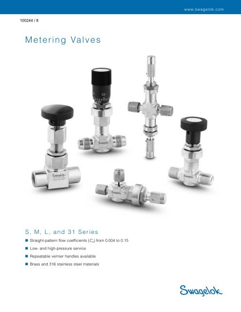
www.swagelok.com<strong>Metering</strong> <strong>Valves</strong>S, M, L, <strong>and</strong> <strong>31</strong> <strong>Series</strong>■ Straight-pattern flow coefficients (C v ) from 0.004 to 0.15■ Low- <strong>and</strong> high-pressure service■ Repeatable vernier h<strong>and</strong>les available■ Brass <strong>and</strong> <strong>31</strong>6 stainless steel materials
2 <strong>Metering</strong> <strong>Valves</strong>FeaturesLow-Pressure <strong>Valves</strong> (S, M, <strong>and</strong> L <strong>Series</strong>)■ Straight-pattern flow coefficients (C v ) from 0.004 to 0.15■ Forged-body <strong>31</strong>6 SS or brass construction■ Straight, angle, cross, <strong>and</strong> double patterns■ Panel mounting■ Knurled, round, vernier, slotted, <strong>and</strong> adjustable-torqueh<strong>and</strong>les■ Swagelok ® tube fitting, male NPT, <strong>and</strong> integral VCR ® fittingend connectionsTechnical Data<strong>Series</strong>SMLPressure-TemperatureRatingsTemperature°F (°C)–10 to 400(–23 to 204)—fluorocarbonFKM O-rings;–10 to 300(–23 to 148)—Buna NO-ringsWorkingPressurepsig (bar)2000(137)1000(68.9)➀Orificein. (mm)0.032(0.81)0.056(1.42)0.128(3.25)ShutoffServiceNoNoYesStemTaper(IncludedAngle)1°3°5°Lock screw“locks in” flowsettings (knurled <strong>and</strong>slotted h<strong>and</strong>les)Tapered stem tipaccurately controls gas<strong>and</strong> liquid flow ratesS, M, <strong>and</strong> L <strong>Series</strong>S series valve shown.Stem threadsare isolated fromsystem fluidH<strong>and</strong>le dead-stophelps preventdamage to stem<strong>and</strong> orificeStem O-ringcontains systemfluid➀ Downstream pressure 500 psig (34.4 bar) max when valve requiresadjustment at pressure due to strength limitations of the fine-pitch threads <strong>and</strong>high operating torque.High-Pressure <strong>Valves</strong> (<strong>31</strong> <strong>Series</strong>)■ Flow coefficient of 0.04; orifice of 0.062 in. (1.6 mm)■ <strong>31</strong>6 SS bar stock body■ Straight <strong>and</strong> angle patterns■ Metal-to-metal shutoff■ 2° stem taper (included angle)■ Panel mounting■ Round phenolic h<strong>and</strong>le■ Swagelok tube fitting <strong>and</strong> female NPT end connectionsPressure-Temperature Ratings ➀ASME Class 2080Material Group 2.2Material Name<strong>31</strong>6 SSPacking nutpermits simpleexternaladjustment440C SSregulating stemhardened forenhancedservice lifePacking fullycontained by<strong>31</strong>6 SS gl<strong>and</strong>s toprevent extrusionMetal-to-metalshutoffTemperature, °F (°C)Working pressure, psig (bar)–65 (–53) to 100 (37)200 (93)300 (148)400 (204)450 (232)500 (260)600 (<strong>31</strong>5)650 (343)700 (371)750 (398)800 (426)850 (454)5000 (344)4295 (295)3875 (266)3560 (245)3435 (236)3<strong>31</strong>0 (228)<strong>31</strong>30 (215)3080 (212)3000 (206)2930 (201)2880 (198)2815 (193)<strong>31</strong> <strong>Series</strong>Tapered stem tipaccurately controlsgas <strong>and</strong> liquid flowratesFor more information about ASME classes, material groups, <strong>and</strong> ratings, see theSwagelok Valve Pressure-Temperature Ratings technical bulletin.➀ Ratings based on optional Grafoil ® packing; ratings limited to 450°F (232°C)at 3435 psig (236 bar) with st<strong>and</strong>ard PTFE packing.
<strong>Metering</strong> <strong>Valves</strong> 3Materials of ConstructionLow-Pressure <strong>Valves</strong> (S, M, <strong>and</strong> L <strong>Series</strong>)High-Pressure <strong>Valves</strong> (<strong>31</strong> <strong>Series</strong>)1a21a2341b2327813454 58 67784589699 910S series M series L series1a1bComponentH<strong>and</strong>leH<strong>and</strong>le screwLock screw➀H<strong>and</strong>leH<strong>and</strong>le screw2 Panel mount nutValve Body MaterialsBrass<strong>31</strong>6 SSMaterial Grade/ASTM SpecificationSilver-mist chrome-plated300 SS/A276brass 360/B16Black oxide <strong>and</strong> light oil-coated alloy steel/ANSI 18.3Green anodized aluminum 6061-T651/B211Black oxide <strong>and</strong> light oil-coated alloy steel/ANSI 18.3Silver-mist chrome-platedbrass 360/B163 Bonnet sleeve Sintered <strong>31</strong>6 SS<strong>31</strong>6 SS/A479—S, M;<strong>31</strong>6 SS/B783—L4 BonnetSilver-mist chrome-platedbrass 345/B435<strong>31</strong>6 SS/A4795 Stem guide ring Glass-filled PTFE6 Body extension ➁ Silver-mist chrome-platedbrass 345/B435<strong>31</strong>6 SS/A4797 Body seal ➁ Buna N Fluorocarbon FKM8 Stem<strong>31</strong>6 SS/A479 Hard chrome-plated <strong>31</strong>6 SS/A479O-ringsBuna NFluorocarbon FKM9 BodySilver-mist chrome-platedbrass 377/B283<strong>31</strong>6 SS/A182LubricantsMolybdenum-disulfide based; silicone basedWetted components listed in italics.➀ Anaerobic-type adhesive.➁ Straight <strong>and</strong> double-pattern M series valves.Material Grade/Component ASTM Specification1 H<strong>and</strong>lePhenolic/D4617Nickel-cadmiumSet screwplated steel2 Packing nut<strong>31</strong>6 SS/A2763 Upper gl<strong>and</strong>4 Packing PTFE/D17105 Lower gl<strong>and</strong> <strong>31</strong>6 SS/A2766 Stem 440C SS/A2767 Panel nut <strong>31</strong>6 SS/B7838 Union nut <strong>31</strong>6 SS/A2769 Bonnet<strong>31</strong>6 SS/A47910 BodyNickel antiseize withLubricanthydrocarbon carrierTestingThe Swagelok S <strong>and</strong> M metering valve designs have beenshell tested to a requirement of no detectable leakage with aliquid leak detector.Every Swagelok L series metering valve is tested for bubbletightshutoff at 100 psig (6.8 bar) differential pressure.Every Swagelok <strong>31</strong> series needle valve is factory tested withnitrogen at 1000 psig (69 bar). Seats have a maximumallowable leak rate of 0.1 std cm 3 /min.Cleaning <strong>and</strong> PackagingEvery Swagelok metering valve is cleaned <strong>and</strong> packaged inaccordance with Swagelok Specification SC-10. Cleaning <strong>and</strong>packaging in accordance with Special Cleaning <strong>and</strong>Packaging (SC-11) is st<strong>and</strong>ard for metering valves with VCRface seal fitting end connections, <strong>and</strong> is available as anoption for all others.
4 <strong>Metering</strong> <strong>Valves</strong>Flow Data at 70°F (20°C)S <strong>Series</strong>Flow Coefficient at Turns OpenFlow Coefficient (C v )0.00400.00350.00300.00250.00200.00150.00100.000500 2 4 6 8 10Number of Turns OpenMaximum Flow—0.004 C vPressureDrop toAtmospherepsi (bar)Air Flowstd ft 3 /min(std L/min)Water FlowU.S. gal/min(L/min)10 (0.68) 0.04 (1.1) 0.01 (0.03)50 (3.4) 0.10 (2.8) 0.02 (0.07)100 (6.8) 0.20 (5.6) 0.04 (0.15)Factory Flow SettingThe h<strong>and</strong>le dead stop is set at 4 to 10std cm 3 /min with 15 psig (1.0 bar) inletpressure.Ordering InformationSelect an ordering number.S, M, <strong>and</strong> L <strong>Series</strong>For brass S, M, <strong>and</strong> L series valves,replace SS with B.Example: B-SS1GpanelholeStraight patternENAM <strong>Series</strong>Flow Coefficient at Turns OpenFlow Coefficient (C v )0.0300.0250.0200.0150.0100.005002 4 6Number of Turns OpenL <strong>Series</strong>Flow Coefficient at Turns Open8Maximum Flow—0.03 C vPressureDrop toAtmospherepsi (bar)Air Flowstd ft 3 /min(std L/min)Maximum Flow—0.15 C vWater FlowU.S. gal/min(L/min)10 (0.68) 0.33 (9.3) 0.09 (0.34)50 (3.4) 0.90 (25.4) 0.21 (0.79)100 (6.8) 1.5 (42.4) 0.30 (1.1)SWAGELOKM series valve shown.S series—0.16 in. (4.1 mm) maximum panelthickness.M <strong>and</strong> L series—0.13 in. (3.3 mm) maximum panelthickness.<strong>31</strong> <strong>Series</strong>For angle-pattern <strong>31</strong> series valves, add-A to the ordering number.Example: SS-<strong>31</strong>RS4-ABSWAGELOKFlow Coefficient (C v )Flow Coefficient (C v )0.1400.1200.1000.0800.0600.0400.0200.0400.0350.0300.0250.0200.015000.0100.0052 4 6 8Number of Turns Open<strong>31</strong> <strong>Series</strong>Flow Coefficient at Turns Open10PressureDrop toAtmospherepsi (bar)Shutoff ServiceAir Flowstd ft 3 /min(std L/min)Stainless steel L series valves are notrecommended for shutoff in vacuum orgas service, or for repetitive shutoff inliquid service.Maximum Flow—0.04 C vWater FlowU.S. gal/min(L/min)10 (0.68) 1.6 (45.3) 0.47 (1.7)50 (3.4) 4.5 (127) 1.0 (3.7)100 (6.8) 7.9 (223) 1.5 5.6)PressureDrop toAtmospherepsi (bar)Air Flowstd ft 3 /min(std L/min)Water FlowU.S. gal/min(L/min)10 (0.68) 0.45 (12.7) 0.12 (0.45)50 (3.4) 1.2 (33.9) 0.28 (1.0)100 (6.8) 2.1 (59.4) 0.40 (1.5)0.38 (9.6)max panelthicknessStraight patternB1.38(35.1)AB0.59 (15.0)panel hole1.09(27.7)3.60(91.4)open0.38(9.6)002 4 6 8 10Number of Turns Open
<strong>Metering</strong> <strong>Valves</strong> 5DimensionsDimensions, in inches (millimeters), arefor reference only <strong>and</strong> are subject tochange.ANDSWAGELOK0.38 (9.6)max panelthicknessAngle patternBESWAGELOKAngle pattern1.38(35.1)Gpanelhole0.59 (15.0)panel holeDHopenEnd ConnectionsInlet/Outlet SizeSwageloktube fittingsMale VCRfittingOrderingNumber1/16 in. SS-SS11/8 in. SS-SS21/4 in. SS-SS43 mm SS-SS3MM6 mm SS-SS6MM1/4 in.SS-SVR4Dimensions, in. (mm)A B D E G NS series straight pattern1.56 (39.6)2.34 (59.4)1.90 (48.3)2.04 (51.8)1.90 (48.3)2.04 (51.8)2.06 (52.3)S series angle pattern1/16 in. SS-SS1-A 3.22 (81.8) 0.81 (20.6) 0.88 (22.4)Swageloktube fittings1/8 in.1/4 in.SS-SS2-ASS-SS4-A3.32 (84.3)3.36 (85.3)0.98 (24.9)1.02 (25.9)3 mm SS-SS3MM-A 3.32 (84.3) 0.98 (24.9) 0.99 (25.1)Male NPT/Swagelok 1/8 in. SS-SM2-S2-A 3.07 (78.0) 0.98 (24.9)tube fittingM series straight pattern1/8 in. SS-2MG2.02 (51.3)Swagelok 1/4 in. SS-4MG2.20 (55.9)tube fittings 3 mm SS-3MG-MM2.02 (51.3)6 mm SS-6MG-MM2.20 (55.9)Male NPT1/8 in. SS-2MG2 2.78 (70.6) 1.50 (38.1) —1/4 in. SS-4MG21.96 (49.8)Female NPT 1/8 in. SS-2MG4 1.94 (49.3)Male VCRfittings1/4 in. SS-MGVR4 2.06 (52.3)M series angle pattern1/8 in. SS-2MA 3.30 (83.8) 1.01 (25.7)Swagelok 1/4 in. SS-4MA 3.39 (86.1) 1.10 (27.9)tube fittings 3 mm SS-3MA-MM 3.30 (83.8) 1.01 (25.7)6 mm SS-6MA-MM 3.39 (86.1) 1.10 (27.9)Male NPT1/8 in. SS-2MA2 3.04 (77.2) 0.75 (19.1)1/4 in. SS-4MA2 3.27 (83.1) 0.98 (24.9) 1.02 (25.9)Male NPT/to Swagelok 1/8 in. SS-2MA1 3.04 (77.2) 1.01 (25.7) 0.75 (19.1)tube fittingFemale NPT 1/8 in. SS-2MA4 3.26 (82.8) 0.97 (24.6)L series straight pattern1/4 in. SS-4L2.34 (59.4)Swagelok3/8 in. SS-6L2.46 (62.5)tube fittings2.82 (71.6)—6 mm SS-6L-MM2.34 (59.4)Male NPT 1/4 in. SS-4L22.00 (50.8)L series angle patternSwagelok 1/4 in. SS-4LAtube fittings 6 mm SS-6LA-MM3.77 (95.8) 1.17 (29.7)—0.38(9.6)0.38(9.6)0.50(12.7)0.50(12.7)1.13(28.7)1.13(28.7)0.45(11.4)0.45(11.4)0.58(14.7)0.58(14.7)0.58(14.7)0.58(14.7)0.92(23.4)0.92(23.4)1.56(39.6)1.07(27.2)1.26(32.0)1.04(26.4)SWAGELOKB2End ConnectionsTypeSizeOrderingNumberDimensions, in. (mm)A B B1 B2 C D H<strong>31</strong> series0.38(9.6)SWAGELOKB1CSwageloktube fittingFemaleNPT1/4 in. SS-<strong>31</strong>RS46 mm SS-<strong>31</strong>RS6MM1/8 in.1/4 in.SS-<strong>31</strong>RF2SS-<strong>31</strong>RF42.40(61.0)2.00(50.8)2.06(52.3)1.20(30.5)1.00(25.4)1.03(26.2)1.16(29.5)0.91(23.1)1.48(37.6)1.00(25.4)1.54(39.1)1.09(27.7)1.28 (32.5)3.60(91.4)3.80(96.5)Dimensions shown with Swagelok tube fitting nuts finger-tight.
6 <strong>Metering</strong> <strong>Valves</strong>Options <strong>and</strong> AccessoriesCross PatternS <strong>and</strong> M <strong>Series</strong>■ Fluid flows between side ports aroundstem in any stem position.■ Flow through branch port can bemetered in both directions.GpanelholeENASWAGELOKS series valve shown.Double PatternS <strong>and</strong> M <strong>Series</strong>■ Inlet valve h<strong>and</strong>le can be set <strong>and</strong>locked at desired maximum flow.■ Outlet valve h<strong>and</strong>le can be used forfine flow control up to the presetmaximum of the inlet valve.NASWAGELOKSWAGELOKSWAGELOKDBGpanelholeESWAGELOKM series valve shown.BOrdering Information <strong>and</strong> DimensionsSelect an ordering number. For brass valves, replace SS with B.Example: B-SS2-XDimensions are for reference only <strong>and</strong> are subject to change.ValvePatternCrossDoubleCrossDoubleEnd ConnectionsOrderingType Size C v NumberSwageloktube fittingSwageloktube fitting1/8 in.1/8 in.1/4 in.1/4 in.0.0040.0010.030.026Dimensions shown with Swagelok tube fitting nuts finger-tight.SS-SS2-XSS-SS2-DSS-4MXSS-4MGDDimensions, in. (mm)A B D E G NS series3.32 (84.3) 1.96 (49.8) 0.98 (24.9)2.34 (59.4) 1.90 (48.3) —0.38 (9.6) 0.45 (11.4) 0.92 (23.4)M series3.39 (86.1) 1.10 (27.9)1.07 (27.2)0.50 (12.7) 0.58 (14.7)2.78 (70.6) 2.20 (55.9) —1.56 (39.6)
Stem O-Ring MaterialsS, M, <strong>and</strong> L <strong>Series</strong>Buna N O-rings are st<strong>and</strong>ard for brass valves; fluorocarbonFKM O-rings are st<strong>and</strong>ard for stainless steel valves.For an optional stem O-ring, add the desired O-ring materialdesignator to the ordering number.Example: SS-SS1-BUSC-11 Cleaning <strong>and</strong> PackagingAll <strong>Series</strong>To order special cleaning <strong>and</strong> packaging in accordance withSpecification SC-11, if it is not st<strong>and</strong>ard, add -SC11 to thevalve ordering number.Example: SS-SS1-SC11O-ring MaterialBuna NEthylene propyleneDesignator-BU-EPTemperature Rating,°F (°C)–10 to 300 (–23 to 149)Fluorocarbon FKM -VI –10 to 400 (–23 to 204)Kalrez ® -KZ 0 to 300 (–18 to 149)Neoprene -NE –10 to 250 (–23 to 121)High-Temperature Stem Packing Material<strong>31</strong> <strong>Series</strong>Grafoil packing extends the temperature rating to 850°F(454°C) <strong>and</strong> requires fluorinated tungsten disulfide-basedlubricant. To order, add -G to the ordering number.Example: SS-<strong>31</strong>RS4-GStem Packing KitsPTFE <strong>and</strong> Grafoil packing kits are available. Kits includepacking, lubricant, <strong>and</strong> instructions. Select a kit orderingnumber.Stem Packing Material <strong>and</strong> Kit Ordering NumberPTFET-9K-2Lubricant: nickel antiseize,hydrocarbon carrierGrafoilG-9K-2Lubricant: fluorinatedtungsten disulfide based Packing adjustment may be required during thevalve’s service life.Safe Product SelectionWhen selecting a product, the total system design mustbe considered to ensure safe, trouble-free performance.Function, material compatibility, adequate ratings,proper installation, operation, <strong>and</strong> maintenance are theresponsibilities of the system designer <strong>and</strong> user.Caution: Do not mix or interchange parts with those ofother manufacturers.Swagelok, VCR—TM Swagelok CompanyGrafoil—TM UCAR Carbon Company Inc.Kalrez—TM DuPont© 2002 Swagelok CompanyPrinted in U.S.A., MIAugust 2002, R3MS-01-142


