Download PDF
Download PDF Download PDF
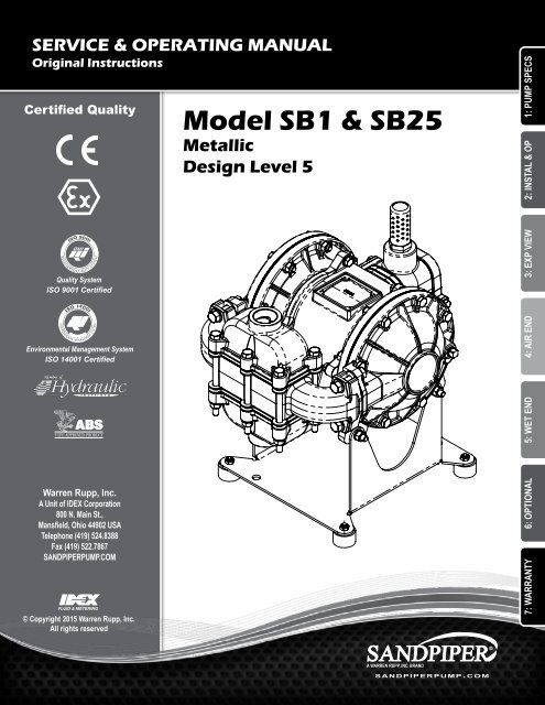
"B"SERVICE & OPERATING MANUALOriginal InstructionsCertified QualityModel SB1 & SB253 2 1MetallicDesign Level 51: PUMP SPECS2: INSTAL & OPQuality SystemISO 9001 CertifiedAIR EXHAUST3/4" NPT3: EXP VIEWDEnvironmental Management SystemISO 14001 CertifiedAIR INLET1/2" NPT4: AIR END5: WET ENDC6.89175Warren Rupp, Inc.A Unit of IDEX Corporation800 N. Main St.,Mansfield, Ohio 44902 USATelephone (419) 524.8388Fax (419) 522.7867SANDPIPERPUMP.COM© Copyright 2015 Warren Rupp, Inc.All rights reservedSB1 / SB25HEAVY DUTY BALL VALVE PUMPDIMENSIONAL TOLERANCE 1/8 [3][XX] = MILLIMETERSsandpiperpump.com6: OPTIONAL7: WARRANTYB
- Page 2 and 3: Safety InformationIMPORTANTWARNINGR
- Page 4 and 5: Explanation of Pump Nomenclature1:
- Page 6 and 7: 1: PUMP SPECSDimensional DrawingsSB
- Page 8 and 9: Principle of Pump OperationAir-Oper
- Page 10 and 11: 2: INSTAL & OPTroubleshooting Guide
- Page 12 and 13: 3: EXP VIEWComposite Repair Parts L
- Page 14 and 15: Air Distribution Valve AssemblyWith
- Page 16 and 17: Pilot Valve Assembly4F4A4E4C4D4B4:
- Page 18 and 19: Diaphragm ServicingStep 1: With man
- Page 20 and 21: Written Warranty5 - YEAR Limited Pr
- Page 22: EC Declaration of ConformityATEX Su
"B"SERVICE & OPERATING MANUALOriginal InstructionsCertified QualityModel SB1 & SB253 2 1MetallicDesign Level 51: PUMP SPECS2: INSTAL & OPQuality SystemISO 9001 CertifiedAIR EXHAUST3/4" NPT3: EXP VIEWDEnvironmental Management SystemISO 14001 CertifiedAIR INLET1/2" NPT4: AIR END5: WET ENDC6.89175Warren Rupp, Inc.A Unit of IDEX Corporation800 N. Main St.,Mansfield, Ohio 44902 USATelephone (419) 524.8388Fax (419) 522.7867SANDPIPERPUMP.COM© Copyright 2015 Warren Rupp, Inc.All rights reservedSB1 / SB25HEAVY DUTY BALL VALVE PUMPDIMENSIONAL TOLERANCE 1/8 [3][XX] = MILLIMETERSsandpiperpump.com6: OPTIONAL7: WARRANTYB
Safety InformationIMPORTANTWARNINGRead the safety warnings and instructions in this manualbefore pump installation and start-up. Failure to comply withthe recommendations stated in this manual could damage thepump and void factory warranty.When the pump is used for materials that tend to settle outor solidify, the pump should be flushed after each use toprevent damage. In freezing temperatures the pump should becompletely drained between uses.CAUTIONBefore pump operation, inspect all fasteners for looseningcaused by gasket creep. Retighten loose fasteners to preventleakage. Follow recommended torques stated in this manual.Nonmetallic pumps and plastic components are not UVstabilized. Ultraviolet radiation can damage these parts andnegatively affect material properties. Do not expose to UV lightfor extended periods of time.WARNINGPump not designed, tested or certified to be powered bycompressed natural gas. Powering the pump with naturalgas will void the warranty.When used for toxic or aggressive fluids, the pump shouldalways be flushed clean prior to disassembly.Before maintenance or repair, shut off the compressed air line,bleed the pressure, and disconnect the air line from the pump.Be certain that approved eye protection and protective clothingare worn at all times. Failure to follow these recommendationsmay result in serious injury or death.Airborne particles and loud noise hazards. Wear eye and earprotection.In the event of diaphragm rupture, pumped material may enterthe air end of the pump, and be discharged into the atmosphere.If pumping a product that is hazardous or toxic, the air exhaustmust be piped to an appropriate area for safe containment.Take action to prevent static sparking. Fire or explosion canresult, especially when handling flammable liquids. The pump,piping, valves, containers and other miscellaneous equipmentmust be properly grounded.This pump is pressurized internally with air pressure duringoperation. Make certain that all fasteners are in good conditionand are reinstalled properly during reassembly.Use safe practices when liftingkgGrounding the PumpTo be fully groundable, the pumps must be ATEX Compliant. Refer to the nomenclature page for ordering information.Optional 8 foot long (244 centimeters) Ground Strap is available for easy ground connection.To reduce the risk of static electrical sparking, this pump must be grounded. Check the localelectrical code for detailed grounding instruction and the type of equipment required.Refer to nomenclature page for ordering information.WARNINGTake action to prevent static sparking.Fire or explosion can result, especiallywhen handling flammable liquids. Thepump, piping, valves, containers orother miscellaneous equipment mustbe grounded.Model SB1/SB25sandpiperpump.comsb1dl5sm-rev0515
Table of ContentsSECTION 1: PUMP SPECIFICATIONS................1• Explanation of Nomenclature• Performance• Materials• Dimensional Drawings1: PUMP SPECSSECTION 2: INSTALLATION & OPERATION......5• Principle of Pump Operation• Recommended Installation Guide• Troubleshooting Guide2: INSTAL & OPSECTION 3: EXPLODED VIEW...........................8• Composite Repair Parts Drawing• Composite Repair Parts List• Material CodesSECTION 4: AIR END.......................................11• Air Valve Assembly for Aluminum Center Sections• Air Valve Assembly for Cast Iron Center Sections• Pilot Valve AssemblySECTION 5: WET END......................................15• Diaphragm Drawings• Diaphragm ServicingSECTION 6: OPTIONAL CONFIGURATIONS....17• Dual PortSECTION 7: WARRANTY & CERTIFICATES.....19• Warranty• EC Declaration of Conformity - Machinery• EC Declaration of Conformity - ATEX• EC Summary of Markings7: WARRANTY3: EXP VIEW4: AIR END5: WET END6: OPTIONALsb1dl5sm-rev0515sandpiperpump.comModel SB1/SB25
Explanation of Pump Nomenclature1: PUMP SPECSYour Model #:(fill in from pumpnameplate)__ __ _____ __ ___ __ __Pump Pump Pump Size Discharge Diaphragm/ DesignSeries Design and Options Porting Valve LevelConstructionModel #: XX X XXXXXX, XX XXX X XXPump SeriesS SANDPIPER ®Pump DesignB Soilid BallPump Size1 1"25 1" BSPT (Tapered Thread)Discharge Porting PositionD BottomS SideT TopET Dual TopES Dual SideOptionsP1 Intrinsically Safe ATEX CompliantPulse OutputDiaphragm Check Valve MaterialsB NitrileC FKM with PTFEF FDA Accepted White NitrileGN Neoprene Backup with PTFE Overlayand PTFE Check BallsGR Hytrel Backup w/PTFE Overlay/PTFE BallsGZ PTFE/Nitrile BondedOne-Piece/PTFE BallsH EPDM with PTFEN NeopreneR HytrelS SantopreneV FKMDesign Level5ConstructionA Aluminum Wetted, Aluminum AirSI Stainless Steel Wetted, Cast Iron AirSS Stainless Steel Wetted, Aluminum AirHC Alloy-C Wetted, Aluminum AirHI Alloy-C Wetted, Cast Iron AirYour Serial #: (fill in from pump nameplate)______________________________________ATEX Detail(1)II 1G c T5 Models equipped with Construction designationsII 2GD T5II 3/1 G c T5SI or HI. Note: See ATEX Explanation of TypeCertificateII 1D c T100°CI M1 cI M2 cII 2G c T5II 2GD 3/2 G T5c T5II 2D c T100°CModels equipped with Construction designations A,SI, SS, HC, or HI. Note: See ATEX Explanation ofType Examination CertificateII II 2G Ex Ex ia ia c c IIC IIC T5 T5(2)II 3/2 2D c G iaD Ex 20 ia IP67 c IIC T100˚C T5II 2D Ex c ia 20 IP67T100°CNote: Pumps ordered with the options listed in (1) to the left areATEX compliant when ordered with kit option P1.1 • Model SB1 & SB25sandpiperpump.comsb1dl5sm-rev0515
PerformanceSB1 & SB25SUCTION/DISCHARGE PORT SIZE• SB1: 1” (25.4mm) NPT(F)• SB25: 1” (25.4mm) BSP TaperedCAPACITY• 0 to 42 gallons per minute(0 to 159 liters per minute)AIR DISTRIBUTION VALVE• No-lube, no-stall designSOLIDS-HANDLING• Up to nearly .25 in. (6.3mm)HEADS UP TO• 125 psi or 289 ft. of water(8.8 Kg/cm 2 or 88 meters)MAXIMUM OPERATING PRESSURE• 125 psi (8.6 bar)DISPLACEMENT/STROKE• .09 Gallon / .34 literSHIPPING WEIGHT• Aluminum 31 lbs. (14kg)• Stainless Steel 45 lbs. (20kg)• Alloy C 45 lbs. (20kg)HEADBAR• Stainless Steel with Cast Iron Center 65 lbs. (30kg)• Alloy C with Cast Iron Center 65 lbs. (30kg)MaterialsMaterial Profile:76543210PSI1009080CAUTION! Operating temperature limitations are as follows:Conductive Acetal: Tough, impact resistant, ductile. Goodabrasion resistance and low friction surface. Generally inert, withgood chemical resistance except for strong acids and oxidizingagents.EPDM: Shows very good water and chemical resistance. Haspoor resistance to oils and solvents, but is fair in ketones andalcohols.FKM: (Fluorocarbon) Shows good resistance to a wide rangeof oils and solvents; especially all aliphatic, aromatic andhalogenated hydrocarbons, acids, animal and vegetable oils.Hot water or hot aqueous solutions (over 70°F(21°C)) willattack FKM.Hytrel®: Good on acids, bases, amines and glycols at roomtemperatures only.Neoprene: All purpose. Resistance to vegetable oils. Generallynot affected by moderate chemicals, fats, greases and manyoils and solvents. Generally attacked by strong oxidizing acids,ketones, esters and nitro hydrocarbons and chlorinated aromatichydrocarbons.Nitrile: General purpose, oil-resistant. Shows good solvent, oil,water and hydraulic fluid resistance. Should not be used withhighly polar solvents like acetone and MEK, ozone, chlorinatedhydrocarbons and nitro hydrocarbons.Nylon: 6/6 High strength and toughness over a widetemperature range. Moderate to good resistance to fuels, oilsand chemicals.100 PSI80 PSI10(17)15(25.5)20(34)25(42.5)30(51)706035(59.5)40(68)5045(76.5)4050(85)3020100 0 4 8 12 16 20 24 28 32 36 40U.S. Gallons per minute60 PSI40 PSIAIR CONSUMPTIONSCFM (M 3 /hr)20 PSI Air Inlet PressureMODEL SB1/SB25 Performance CurvePerformance based on the following: elastomer fitted pump, flooded suction,water at ambient conditions. The use of other materials and varying hydraulicconditions may result in deviations in excess of 5%.0 25 50 75 100 125 150Liters per minuteCAPACITYOperatingTemperatures:Max. Min.190°F88°C280°F138°C350°F177°C220°F104°C200°F93°C190°F88°C180°F82°C-20°F-29°C-40°F-40°C-40°F-40°C-20°F-29°C-10°F-23°C-10°F-23°C32°F0°CPolypropylene: A thermoplastic polymer. Moderate tensileand flex strength. Resists stong acids and alkali. Attacked bychlorine, fuming nitric acid and other strong oxidizing agents.PVDF: (Polyvinylidene Fluoride) A durable fluoroplastic withexcellent chemical resistance. Excellent for UV applications.High tensile strength and impact resistance.Santoprene®: Injection molded thermoplastic elastomer withno fabric layer. Long mechanical flex life. Excellent abrasionresistance.UHMW PE: A thermoplastic that is highly resistant to a broadrange of chemicals. Exhibits outstanding abrasion and impactresistance, along with environmental stress-cracking resistance.Urethane: Shows good resistance to abrasives. Has poorresistance to most solvents and oils.Virgin PTFE: (PFA/TFE) Chemically inert, virtually impervious.Very few chemicals are known to chemically react with PTFE;molten alkali metals, turbulent liquid or gaseous fluorine anda few fluoro-chemicals such as chlorine trifluoride or oxygendifluoride which readily liberate free fluorine at elevatedtemperatures.180°F82°C250°F121°C275°F135°C180°F82°C150°F66°C220°F104°C32°F0°C0°F-18°C-40°F-40°C-35°F-37°C32°F0°C-35°F-37°CMaximum and Minimum Temperatures are the limits for which these materials can be operated.Temperatures coupled with pressure affect the longevity of diaphragm pump components.Maximum life should not be expected at the extreme limits of the temperature ranges.Metals:Alloy C: Equal to ASTM494 CW-12M-1 specification for nickel and nickel alloy.Stainless Steel: Equal to or exceeding ASTM specification A743 CF-8M for corrosionresistant iron chromium, iron chromium nickel and nickel based alloy castings forgeneral applications. Commonly referred to as 316 Stainless Steel in the pump industry.For specific applications, always consult the Chemical Resistance Chart.Ambient temperature range: -20°C to +40°CProcess temperature range: -20°C to +80°C for models rated as category 1 equipment-20°C to +100°C for models rated as category 2 equipmentIn addition, the ambient temperature range and the process temperature range do not exceed the operating temperature range of the applied non-metallic parts as listed in the manuals of the pumps.1: PUMP SPECSsandpiperpump.com Model SB1 & SB25 • 2sb1dl5sm-rev0515
1: PUMP SPECSDimensional DrawingsSB1 & SB25 Heavy Duty Ball Valve8 7 6 5 4 311.36288DISCHARGE PORT1" NPT (SB1)1" BSPT (SB25)6.12155"C""A""B"AIR EXHAUST3/4" NPT6 5 4 3 2 1"C""B""D"DISCHARGE PORT1" NPT (SB1)1" BSPT (SB25)6.1215512.50317"A"AIR EXHAUST3/4" NPTAIR INLET1/2" NPT9.00229812.503174X4.63118.7218SUCTION PORT1" NPT (SB1)1" BSPT (SB25).28 [7] MOUNTING HOLENOTE:UNIT FURNISHED WITH SUB-BASE PLATEAND RUBBER FEET AS STANDARD. FORSTATIONARY BOLT DOWN USE, RUBBERFEET CAN BE REMOVED.8.56217764X4.63118.7218SUCTION PORT1" NPT (SB1) AIR INLET1" BSPT (SB25) 1/2" NPT6.89175.28 [7] MOUNTING HOLENOTE:UNIT FURNISHED WITH SUB-BASE PLATEAND RUBBER FEET AS STANDARD. FORSTATIONARY BOLT DOWN USE, RUBBERFEET CAN BE REMOVED.PUMPCOFIGURATIONALUMINUMCENTER SECTIONSB1 / SB25HEAVY DUTY BALL VALVE PUMPDIMENSIONAL TOLERANCE 1/8 [3][XX] = MILLIMETERSDIM "A" DIM "B" DIM "C" DIM "D"F.1 REVISED VALVE CONFIGURATION MF 11/9/20116.89175PUMPCOFIGURATIONALUMINUMCENTER SECTION3.95 [100] 5.86 [149] 13.90 [353] 14.55 [370]CAST IRONCENTER SECTION 4.10 [104] 5.54 [141] 13.60 [345] 15.75 [400]PULSE OUTPUTCONFIGURATIONREV REVISION CHG DATE APP DATE ECNSB1 / SBHEAVY DUTY BALL VADIMENSIONAL TOLERAN[XX] = MILLIMETEDIM "A"DIM "B"3.95 [100] 5.86 [149CAST IRONCENTER SECTION 4.10 [104] 5.54 [141PULSE OUTPUTCONFIGURATIONPART NUMBERMATERIALPUMP REFERENCE PR450.060.000MADE FROM6F.1 REVISED VALVE CONFIGURATION MF 11/9/2011REV REVISION CHG DATE APP DATE ECNPART NUMBERMADE FROMMATERIALPUMP REFERENCE PROJECT450.060.000UNLESS OTHERWISESPECIFIEDTOLEARNCESWARREN RUPP , I.XX.XXX.010.005ANGULAR 1/263SURFACE FINSHDO NOT SCALE DRAWINGDIMENSIONS ARE INCHESTHIS IS A PROPRIETARY DOCUMENT. DO NOT REPRODUCE OR DISCLOSEXPRESS WRITTEN PERMISSION OF WARREN RUPP, INCDESCRIPTIONOUTLINE, DIMENSIONAL, SB1450.073.000DRAWING NUMBERSH3 • Model SB1 & SB25sandpiperpump.comsb1dl5sm-rev0515
"D""D"11.3628811.36288DISCHARGE PORT1" NPT (SB1)1" BSPT (SB25)DISCHARGE PORT1" NPT (SB1)1" BSPT (SB25)8.432147.621947.62194"C""C""B""A""B""A"AIR EXHAUST3/4" NPTAIR EXHAUST3/4" NPTAIR INLET1/2" NPTAIR INLET6.82 1/2" NPT1731: PUMP SPECS9.002299.002298.562178.562178.43214.64.721618SUCTION PORT1" NPT (SB1)1" BSPT (SB25).64.72164X .28 [7] MOUNTING HOLE 18SUCTION PORTNOTE: 1" NPT (SB1)UNIT 1" FURNISHED BSPT (SB25) WITH SUB-BASE PLATEAND RUBBER FEET AS STANDARD. FORSTATIONARY BOLT DOWN USE, RUBBER4X FEET .28 CAN [7] MOUNTING BE REMOVED. HOLENOTE:UNIT FURNISHED WITH SUB-BASE PLATEAND RUBBER FEET AS STANDARD. FORSTATIONARY BOLT DOWN USE, RUBBER HEAVY DUTY FLAP VALVE PUMPFEET CAN BE REMOVED.BOTTOM PORTEDDIMENSIONAL TOLERANCE 1/8 [3][XX] = MILLIMETERSPUMPCOFIGURATIONALUMINUMCENTER SECTION6.82173DIM "A" DIM "B" DIM "C" DIM "D"HEAVY DUTY FLAP VALVE PUMPBOTTOM PORTEDDIMENSIONAL TOLERANCE 1/8 [3]3.95 [100] 5.86 [149] 15.36 [390] 14.49 [368]CAST IRON[XX] = MILLIMETERSCENTER SECTION 4.10 [104] 5.54 [141] 15.06 [383] 15.69 [398]PULSE PUMP OUTPUTCOFIGURATIONCONFIGURATION DIM "A" DIM "B" DIM "C" DIM "D"ALUMINUMCENTER SECTION3.95 [100] 5.86 [149] 15.36 [390] 14.49 [368]CAST IRONCENTER SECTION 4.10 [104] 5.54 [141] 15.06 [383] 15.69 [398]PULSE OUTPUTCONFIGURATIONsandpiperpump.com Model SB1 & SB25 • 4sb1dl5sm-rev0515
Principle of Pump OperationAir-Operated Double Diaphragm (AODD) pumps are poweredby compressed air or nitrogen.2: INSTAL & OPAir LineDischargedFluidThe main directional (air) control valve 1 distributescompressed air to an air chamber, exerting uniform pressureover the inner surface of the diaphragm 2. At the same time,the exhausting air 3 from behind the opposite diaphragmis directed through the air valve assembly(s) to an exhaustport 4.As inner chamber pressure (P1) exceeds liquid chamberpressure (P2), the rod 5 connected diaphragms shifttogether creating discharge on one side and suction on theopposite side. The discharged and primed liquid’s directionsare controlled by the check valves (ball or flap)6 orientation.The pump primes as a result of the suction stroke. Thesuction stroke lowers the chamber pressure (P3) increasingthe chamber volume. This results in a pressure differentialnecessary for atmospheric pressure (P4) to push the fluidthrough the suction piping and across the suction side checkvalve and into the outer fluid chamber 7.DischargeStrokeSuctionStrokePUMP INSTALLATION AREASuction (side) stroking also initiates the reciprocating SAFE AIREXHAUST(shifting, stroking or cycling) action of the pump. DISPOSAL The suctiondiaphragm’s movement is mechanically pulled through AREA its1" DIAMETER stroke. AIR The diaphragm’s inner plate makes contact with anEXHAUST PIPING actuator plunger aligned to shift the pilot signaling valve.Once actuated, the pilot valve sends a pressure MUFFLER signal to theopposite end of the main directional air valve, redirecting thecompressed air to the opposite inner chamber.PrimedFluidSUBMERGED ILLUSTRATIONMUFFLERLIQUIDLEVEL1" DIAMETER AIREXHAUST PIPINGSUCTIONLINEPump can be submerged if the pump materials of constructionare compatible with the liquid being pumped. The air exhaustmust be piped above the liquid level. When the MUFFLER pumped productsource is at a higher level than the pump (flooded suctioncondition), pipe the exhaust higher than the product source toprevent siphoning spills.LIQUIDLEVEL1" DIAMETER AIREXHAUST PIPING5 • Model SB1 & SB25SUCTIONLINEsandpiperpump.comsb1dl5sm-rev0515
Recommended Installation GuideAvailable Accessories:1. Surge Suppressor2. Filter/Regulator3. Air DryerUnregulated AirSupply to SurgeSuppressor1Surge SuppressorPressure GaugeNote: Surge Suppressor andPiping must be supported afterthe flexible connectionPipe Connection(Style Optional)Flexible ConnectorShut-Off ValveDischarge2: INSTAL & OPCheckValveMuffler(Optional Piped Exhaust)Drain PortShut-OffValveFlexible Connector2Air InletVacuumGaugeFlexibleConnector3Filter RegulatorP/N: 020.V107.000SuctionShut-Off ValveDrain PortPipe Connection(Style Optional)Air DryerNote: Pipe weight should not be supportedby pump connections.CAUTIONThe air exhaust shouldbe piped to an areafor safe dispositionof the product beingpumped, in the event ofa diaphragm failure.Installation And Start-UpLocate the pump as close to the product being pumped as possible. Keep the suction line length and number of fittings to a minimum. Do not reduce the suction linediameter.Air SupplyConnect the pump air inlet to an air supply with sufficient capacity and pressure to achieve desired performance. A pressure regulating valve should be installed toinsure air supply pressure does not exceed recommended limits.Air Valve LubricationThe air distribution system is designed to operate WITHOUT lubrication. This is the standard mode of operation. If lubrication is desired, install an air line lubricatorset to deliver one drop of SAE 10 non-detergent oil for every 20 SCFM (9.4 liters/sec.) of air the pump consumes. Consult the Performance Curve to determine airconsumption.Air Line MoistureWater in the compressed air supply may cause icing or freezing of the exhaust air, causing the pump to cycle erratically or stop operating. Water in the air supply canbe reduced by using a point-of-use air dryer.Air Inlet And PrimingTo start the pump, slightly open the air shut-off valve. After the pump primes, the air valve can be opened to increase air flow as desired. If opening the valveincreases cycling rate, but does not increase the rate of flow, cavitation has occurred. The valve should be closed slightly to obtain the most efficient air flow to pumpflow ratio.sandpiperpump.com Model SB1 & SB25 • 6sb1dl5sm-rev0515
2: INSTAL & OPTroubleshooting GuideSymptom: Potential Cause(s): Recommendation(s):Pump Cycles OncePump Will Not Operate/ CyclePump Cycles and WillNot Prime or No FlowPump Cycles RunningSluggish / Stalling,Flow UnsatisfactoryProduct LeakingThrough ExhaustPremature DiaphragmFailureDeadhead (system pressure meets or exceeds airsupply pressure).Increase the inlet air pressure to the pump. Pump is designed for 1:1 pressure ratio at zero flow.(Does not apply to high pressure 2:1 units).Air valve or intermediate gaskets installed incorrectly. Install gaskets with holes properly aligned.Bent or missing actuator plunger.Remove pilot valve and inspect actuator plungers.Pump is over lubricated.Set lubricator on lowest possible setting or remove. Units are designed for lube free operation.Lack of air (line size, PSI, CFM).Check the air line size and length, compressor capacity (HP vs. cfm required).Check air distribution system.Disassemble and inspect main air distribution valve, pilot valve and pilot valve actuators.Discharge line is blocked or clogged manifolds. Check for inadvertently closed discharge line valves. Clean discharge manifolds/piping.Deadhead (system pressure meets or exceeds air Increase the inlet air pressure to the pump. Pump is designed for 1:1 pressure ratio at zero flow.supply pressure).(Does not apply to high pressure 2:1 units).Blocked air exhaust muffler.Remove muffler screen, clean or de-ice, and re-install.Pumped fluid in air exhaust muffler.Disassemble pump chambers. Inspect for diaphragm rupture or loose diaphragm plate assembly.Pump chamber is blocked.Disassemble and inspect wetted chambers. Remove or flush any obstructions.Cavitation on suction side.Check suction condition (move pump closer to product).Check valve obstructed. Valve ball(s) not seating Disassemble the wet end of the pump and manually dislodge obstruction in the check valve pocket.properly or sticking.Clean out around valve ball cage and valve seat area. Replace valve ball or valve seat if damaged.Use heavier valve ball material.Valve ball(s) missing (pushed into chamber orWorn valve ball or valve seat. Worn fingers in valve ball cage (replace part). Check Chemicalmanifold).Resistance Guide for compatibility.Valve ball(s) / seat(s) damaged or attacked by product. Check Chemical Resistance Guide for compatibility.Check valve and/or seat is worn or needs adjusting. Inspect check valves and seats for wear and proper setting. Replace if necessary.Suction line is blocked.Remove or flush obstruction. Check and clear all suction screens or strainers.Excessive suction lift.For lifts exceeding 20’ of liquid, filling the chambers with liquid will prime the pump in most cases.Suction side air leakage or air in product.Visually inspect all suction-side gaskets and pipe connections.Pumped fluid in air exhaust muffler.Disassemble pump chambers. Inspect for diaphragm rupture or loose diaphragm plate assembly.Over lubrication.Set lubricator on lowest possible setting or remove. Units are designed for lube free operation.Icing.Remove muffler screen, de-ice, and re-install. Install a point of use air drier.Clogged manifolds.Clean manifolds to allow proper air flow.Deadhead (system pressure meets or exceeds airsupply pressure).Cavitation on suction side.Lack of air (line size, PSI, CFM).Excessive suction lift.Air supply pressure or volume exceeds system hd.Undersized suction line.Restrictive or undersized air line.Suction side air leakage or air in product.Suction line is blocked.Pumped fluid in air exhaust muffler.Check valve obstructed.Check valve and/or seat is worn or needs adjusting.Entrained air or vapor lock in chamber(s).Diaphragm failure, or diaphragm plates loose.Diaphragm stretched around center hole or bolt holes.Cavitation.Excessive flooded suction pressure.Misapplication (chemical/physical incompatibility).Incorrect diaphragm plates or plates on backwards,installed incorrectly or worn.Increase the inlet air pressure to the pump. Pump is designed for 1:1 pressure ratio at zero flow.(Does not apply to high pressure 2:1 units).Check suction (move pump closer to product).Check the air line size, length, compressor capacity.For lifts exceeding 20’ of liquid, filling the chambers with liquid will prime the pump in most cases.Decrease inlet air (press. and vol.) to the pump. Pump is cavitating the fluid by fast cycling.Meet or exceed pump connections.Install a larger air line and connection.Visually inspect all suction-side gaskets and pipe connections.Remove or flush obstruction. Check and clear all suction screens or strainers.Disassemble pump chambers. Inspect for diaphragm rupture or loose diaphragm plate assembly.Disassemble the wet end of the pump and manually dislodge obstruction in the check valve pocket.Inspect check valves and seats for wear and proper setting. Replace if necessary.Purge chambers through tapped chamber vent plugs. Purging the chambers of air can be dangerous.Replace diaphragms, check for damage and ensure diaphragm plates are tight.Check for excessive inlet pressure or air pressure. Consult Chemical Resistance Chart for compatibilitywith products, cleaners, temperature limitations and lubrication.Enlarge pipe diameter on suction side of pump.Move pump closer to product. Raise pump/place pump on top of tank to reduce inlet pressure.Install Back pressure device (Tech bulletin 41r). Add accumulation tank or pulsation dampener.Consult Chemical Resistance Chart for compatibility with products, cleaners, temperature limitationsand lubrication.Check Operating Manual to check for correct part and installation. Ensure outer plates have not beenworn to a sharp edge.Unbalanced Cycling Excessive suction lift. For lifts exceeding 20’ of liquid, filling the chambers with liquid will prime the pump in most cases.Undersized suction line.Meet or exceed pump connections.Pumped fluid in air exhaust muffler.Suction side air leakage or air in product.Check valve obstructed.Check valve and/or seat is worn or needs adjusting.Entrained air or vapor lock in chamber(s).Disassemble pump chambers. Inspect for diaphragm rupture or loose diaphragm plate assembly.Visually inspect all suction-side gaskets and pipe connections.Disassemble the wet end of the pump and manually dislodge obstruction in the check valve pocket.Inspect check valves and seats for wear and proper setting. Replace if necessary.Purge chambers through tapped chamber vent plugs.For additional troubleshooting tips contact After Sales Support at service.warrenrupp@idexcorp.com or 419-524-83887 • Model SB1 & SB25sandpiperpump.comsb1dl5sm-rev0515
Composite Repair Parts Drawing31271252264251104913165121151932221723253294729235284035304833146244542374183344403362048334694350PTFE CONFIGURATION7213839391813491028315427426194181236525943373462044507281158343: EXP VIEWService & Repair Kits475.283.000 Air End Conversion Kit(Converts from a Conductive Polypropylene AirValve Assembly to the Die Cast Aluminun Air ValveAssembly) Valve Body Assembly, Gaskets, andLonger Capscrews475.284.379 Wet End Conversion Kit(Converts to Ribbed Check Valve Seats andThicker Gaskets) Check Valve Seats, ConductiveNitrile Gaskets, and Longer Capscrews475.284.384 Wet End Conversion Kit(Converts to Ribbed Check Valve Seats andThicker Gaskets) Check Valve Seats, ConductiveNeoprene Gaskets, and Longer Capscrews475.284.608 Wet End Conversion Kit(Converts to Ribbed Check Valve Seats andThicker Gaskets) Check Valve Seats, ConductivePTFE Gaskets, and Longer Capscrews476.311.000 Air End KitSleeve and Spool Set, Pilot Valve Body Assembly,Bumpers, Bushings, Gaskets, O-rings, Seals,Plungers, and Retaining Rings476.341.000 Air End Refurbishment Kit(With new die cast aluminum air valve body)Bumpers, Bushings, Gaskets, O-rings, Seals,Plungers, and Retaining Rings476.313.000 Air End Refurbishment Kit(For cast iron centers with conductivepolypropylene air valve body)Bumpers, Bushings, Gaskets, O-rings, Seals,Plungers, and Retaining Rings476.309.354 Wet End KitSantoprene Diaphragms, Santoprene Check Balls,PTFE Gaskets, and Copper Sealing Washers1651321CAST IRON MID-SECTIONASSEMBLY CONFIGURATION476.309.356 Wet End KitHytrel Diaphragms, Hytrel Check Balls, FiberManifold Gaskets, Conductive Nitrile FlangeGaskets, and Copper Sealing Washers476.309.360 Wet End KitNitrile Diaphragms, Nitrile Check Balls, FiberManifold Gaskets, Conductive Nitrile FlangeGaskets, and Copper Sealing Washers476.309.363 Wet End KitFKM Diaphragms, FKM Check Balls, PTFE Gaskets,and Copper Sealing Washers476.309.365 Wet End KitNeoprene Diaphragms, Neoprene Check Balls, Fiber ManifoldGaskets, Conductive Neoprene Flange Gaskets, andCopper Sealing Washers476.309.633 Wet End KitFKM Diaphragms, PTFE Check Balls, PTFE Gaskets,and Copper Sealing Washers476.309.634 Wet End KitEPDM Diaphragms, PTFE Check Balls, PTFE Gaskets,and Copper Sealing Washers476.309.635 Wet End KitNeoprene Backup Diaphragms, PTFE Overlay Diaphragms,PTFE Check Balls, PTFE Gaskets,and Copper Sealing Washers476.309.638 Wet End KitHytrel Backup Diaphragms, PTFE Overlay Diaphragms, PTFECheck Balls, PTFE Gaskets,and Copper Sealing Washers476.309.651 Wet End KitOne-Piece Bonded PTFE Diaphragms, PTFE Check Balls,PTFE Gaskets,and Copper Sealing Washerssandpiperpump.com Model SB1 & SB25 • 8sb1dl5sm-rev0515
3: EXP VIEWComposite Repair Parts ListItem Part Number Description Qty.1 031.203.000 ASSEMBLY, MAIN AIR VALVE 1031.030.557 ASSEMBLY, AIR VALVE(CAST IRON CENTERS ONLY) 12 050.008.365 BALL, CHECK 4050.008.354 BALL, CHECK 4050.008.356 BALL, CHECK 4050.008.360 BALL, CHECK 4050.008.363 BALL, CHECK 4050.011.600 BALL, CHECK 43 070.012.170 BEARING, SLEEVE 24 095.074.001 PILOT VALVE ASSEMBLY 15 114.007.157 INTERMEDIATE 1114.012.010 BRACKET, INTERMEDIATE(CAST IRON CENTERS ONLY) 16 115.071.330 BRACKET, MOUNTING 17 132.019.360 BUMPER 28 132.022.360 BUMPER, ACTUATOR 29 135.034.506 BUSHING, PLUNGER 210 165.042.157 CAP, AIR INLET, ASS'Y 1165.042.558 CAP, AIR INLET, ASS'Y(CAST IRON CENTERS ONLY) 111 170.029.330 CAPSCREW, HEX HD,5/16-18 X 1.50 1612 170.043.330 CAPSCREW, HEX HD,1/4-20 X 1.00 6170.006.330 CAPSCREW, HEX HD,5/16-18 X 7/8(CAST IRON CENTERS ONLY) 613 170.083.330 CAPSCREW, HEX HD,3/8-16 UNC X 3.75 4170.033.330 CAPSCREW, HEX HD,3/8-16 UNC X 3.25(CAST IRON CENTERS ONLY) 414 170.045.330 CAPSCREW, HEX HD,5/16-18 X 1 1/4 415 170.122.330 CAPSCREW, HEX HD,5/16-18 X 5.00 616 170.063.330 CAPSCREW, HEX HD,1/4-20 X 1.75 117 171.010.330 CAPSCREW, FLANGE LOCK,3/8-16 UNC X 1.75 418 196.012.157 CHAMBER 2196.012.110 CHAMBER, OUTER 2196.012.112 CHAMBER, OUTER 219 196.042.157 CHAMBER, INNER 1196.084.010 CHAMBER, INNER(CAST IRON CENTERS ONLY) 120 196.043.157 CHAMBER, INNER 1196.090.010 CHAMBER, INNER(CAST IRON CENTERS ONLY) 121 286.008.354 DIAPHRAGM 2286.008.356 DIAPHRAGM 2286.008.360 DIAPHRAGM 2286.008.363 DIAPHRAGM 2286.008.364 DIAPHRAGM 2286.008.365 DIAPHRAGM 2286.008.366 DIAPHRAGM 2286.112.000 DIAPHRAGM, ONE-PIECE BONDED 2Item Part Number Description Qty.22 286.015.604 DIAPHRAGM, OVERLAY 223 334.013.110 FLANGE, THREADED PORTING (1" NPT) 2334.013.110E FLANGE, THREADED PORTING (1" BSP) 2334.013.112 FLANGE, THREADED PORTING (1" NPT) 2334.013.112E FLANGE, THREADED PORTING (1" BSP) 2334.013.157 FLANGE, THREADED PORTING (1" NPT) 2334.013.157E FLANGE, THREADED PORTING (1" BSP) 224 350.002.360 FOOT, RUBBER 425 360.057.360 GASKET 126 360.056.379 GASKET 127 360.058.360 GASKET 128 360.030.425 GASKET, MANIFOLD 2360.030.600 GASKET, MANIFOLD 229 360.115.379 GASKET, FLANGE 4360.115.384 GASKET, FLANGE 4360.115.608 GASKET, FLANGE 430 518.006.156 MANIFOLD 1518.006.110 MANIFOLD 1518.006.112 MANIFOLD 131 530.036.000 MUFFLER 132 542.001.330 NUT, SQUARE 133 545.004.330 NUT, HEX, 5/16-18 2634 545.005.330 NUT, HEX, 3/8-16 435 547.002.330 NUT, STOP 436 560.001.360 O-RING 237 560.040.360 O-RING 238 612.022.330 PLATE, DIAPHRAGM, INNER 2612.218.330 PLATE, DIAPHRAGM, INNER(USE WITH ONE-PIECEBONDED DIAPHRAGM) 239 612.101.110 ASSEMBLY, OUTER DIAPHRAGM PLATE 2612.101.112 ASSEMBLY, OUTER DIAPHRAGM PLATE 2612.108.157 ASSEMBLY, OUTER DIAPHRAGM PLATE 240 618.003.330 PLUG, PIPE, 1/4 341 620.007.114 PLUNGER, ACTUATOR 242 675.040.360 RING, SEALING 243 675.042.115 RING, RETAINING 244 685.039.120 ROD, DIAPHRAGM 145 706.013.330 SCREW, MACHINE 446 720.010.375 SEAL, U-CUP 247 722.026.580 SEAT, CHECK VALVE 2722.102.110 SEAT, CHECK VALVE 2722.102.112 SEAT, CHECK VALVE 248 900.004.330 WASHER, LOCK - 5/16 1049 901.005.330 WASHER, FLAT, 3/8 450 901.012.180 WASHER, SEALING 251 901.035.330 WASHER, FLAT, 1/4 7901.035.330 WASHER, FLAT, 1/4(CAST IRON CENTERS ONLY) 152 900.005.330 WASHER, LOCK, 3/8 653 905.001.015 WASHER, TAPER 454 255.012.335 COUPLING, PIPE, 3/4 NPT(CAST IRON CENTERS ONLY) 158 618.003.110 PLUG, PIPE(STAINLESS STEEL ONLY) 2618.003.112 PLUG, PIPE(ALLOY C ONLY) 2618.003.330 PLUG, PIPE(ALUMINUM ONLY) 2LEGEND:= Items contained within Air End Kits= Items contianed within Wet End KitsNote: Kits contain components specific to the material codes.ATEX Compliant9 • Model SB1 & SB25sandpiperpump.comsb1dl5sm-rev0515
Material Codes - The Last 3 Digits of Part Number000.....Assembly, sub-assembly;and some purchased items010.....Cast Iron015.....Ductile Iron020.....Ferritic Malleable Iron080.....Carbon Steel, AISI B-1112110 .....Alloy Type 316 Stainless Steel111 .....Alloy Type 316 Stainless Steel(Electro Polished)112 .....Alloy C113 .....Alloy Type 316 Stainless Steel(Hand Polished)114 .....303 Stainless Steel115 .....302/304 Stainless Steel117 .....440-C Stainless Steel (Martensitic)120.....416 Stainless Steel(Wrought Martensitic)148.....Hardcoat Anodized Aluminum150.....6061-T6 Aluminum152.....2024-T4 Aluminum (2023-T351)155.....356-T6 Aluminum156.....356-T6 Aluminum157.....Die Cast Aluminum Alloy #380158.....Aluminum Alloy SR-319162.....Brass, Yellow, Screw Machine Stock165.....Cast Bronze, 85-5-5-5166.....Bronze, SAE 660170.....Bronze, Bearing Type,Oil Impregnated180.....Copper Alloy305.....Carbon Steel, Black Epoxy Coated306.....Carbon Steel, Black PTFE Coated307.....Aluminum, Black Epoxy Coated308.....Stainless Steel, Black PTFE Coated309.....Aluminum, Black PTFE Coated313.....Aluminum, White Epoxy Coated330.....Zinc Plated Steel332.....Aluminum, Electroless Nickel Plated333.....Carbon Steel, ElectrolessNickel Plated335.....Galvanized Steel337.....Silver Plated Steel351.....Food Grade Santoprene ®353.....Geolast; Color: Black354.....Injection Molded #203-40Santoprene ® Duro 40D +/-5;Color: RED356.....Hytrel ®357.....Injection Molded Polyurethane358.....Urethane Rubber(Some Applications)(Compression Mold)359.....Urethane Rubber360.....Nitrile Rubber Color coded: RED363.....FKM (Fluorocarbon)Color coded: YELLOW364.....EPDM RubberColor coded: BLUE365.....Neoprene RubberColor coded: GREEN366.....Food Grade Nitrile368.....Food Grade EPDM371.....Philthane (Tuftane)374.....Carboxylated Nitrile375.....Fluorinated Nitrile378.....High Density Polypropylene379.....Conductive Nitrile408.....Cork and Neoprene425.....Compressed Fibre426.....Blue Gard440.....Vegetable Fibre500.....Delrin ® 500502.....Conductive Acetal, ESD-800503.....Conductive Acetal, Glass-Filled506.....Delrin ® 150520.....Injection Molded PVDFNatural color540.....Nylon542.....Nylon544.....Nylon Injection Molded550.....Polyethylene551.....Glass Filled Polypropylene552.....Unfilled Polypropylene555.....Polyvinyl Chloride556.....Black Vinyl557.....Conductive Carbon-filled Polypropylene558.....Conductive HDPE570.....Rulon II ®580.....Ryton ®600.....PTFE (virgin material)Tetrafluorocarbon (TFE)603.....Blue Gylon ®604.....PTFE606.....PTFE607.....Envelon608.....Conductive PTFE610.....PTFE Encapsulated Silicon611 .....PTFE Encapsulated FKM632.....Neoprene/Hytrel ®633.....FKM/PTFE634.....EPDM/PTFE635.....Neoprene/PTFE637.....PTFE, FKM/PTFE638.....PTFE, Hytrel ® /PTFE639.....Nitrile/TFE643.....Santoprene ® /EPDM644.....Santoprene ® /PTFE656 .....Santoprene ® Diaphragm andCheck Balls/EPDM Seats661.....EPDM/Santoprene ®666.....FDA Nitrile Diaphragm,PTFE Overlay, Balls, and Seals668.....PTFE, FDA Santoprene ® /PTFE• Delrin and Hytrel are registeredtradenames of E.I. DuPont.• Nylatron is a registered tradenameof Polymer Corp.• Gylon is a registered tradenameof Garlock, Inc.• Santoprene is a registered tradenameof Exxon Mobil Corp.• Rulon II is a registered tradenameof Dixion Industries Corp.• Ryton is a registered tradenameof Phillips Chemical Co.• Valox is a registered tradenameof General Electric Co.RECYCLINGMany components of SANDPIPER ® AODDpumps are made of recyclable materials.We encourage pump users to recycle wornout parts and pumps whenever possible,after any hazardous pumped fluids arethoroughly flushed.3: EXP VIEWsandpiperpump.com Model SB1 & SB25 • 10sb1dl5sm-rev0515
Air Distribution Valve AssemblyWith Aluminum Center1E1D1F1C1B1A1C1F1D1E4: AIR END1E1C1D1FAir Distribution Valve ServicingSee repair parts drawing, remove screws.Step 1: Remove hex capscrews (1E).Step 2: Remove end cap (1D).Step 3: Remove spool part of (1A) (caution: do not scratch).Step 4: Press sleeve (1A) from body (1B).Step 5: Inspect bumpers (1C) and o-rings (1F).Step 6: Lightly lubricate O-Rings (1F) on sleeve (1A).Step 7: Press sleeve (1A) into body (1B).Step 8: Reassemble in reverse order, starting with step 3.Note: Sleeve and spool (1A) set is match ground to a specified clearancesleeve and spools (1A) cannot be interchanged.1BMain Air Valve Assembly Parts ListItem Item Number Description Qty1 031.203.000 Assembly, Main Air Valve 11A 031.039.000 Sleeve & Spool Set 11B 095.113.157 Body, Valve 11C 132.037.357 Bumper 21D 165.129.157 1A Cap, End 21E 170.032.330 1/4-20 X 3/4 Capscrew 81F 560.058.360 7/8 ID X 1/16 CS O-Ring 81DLEGEND:1C= Items contained within Air End Kits1EATEX Compliant1DIMPORTANTRead these instructions completely, before installationand start-up. It is the responsibility of the purchaserto retain this manual for reference. Failure to complywith the recommendations stated in this manual willdamage the pump, and void factory warranty.11 • Model SB1 & SB25sandpiperpump.comsb1dl5sm-rev0515
Air Distribution Valve AssemblyWith Cast Iron Center1F1D1E1E1F1C1D1B1A1D1C1E1D4: AIR ENDAir Distribution Valve ServicingSee repair parts drawing, remove screws.Step 1: Remove end cap retainer (1E).Step 2: Remove end cap (1C).Step 3: Remove spool part of (1A) (caution, do not scratch).Step 4: Press sleeve (1A) from body (1B).Step 5: Inspect O-Ring (1D) and replace if necessary.Step 6: Lightly lubricate O-Rings (1D) on spool (1A).Step 7: Press sleeve (1A) into body (1B).Step 8: Reassemble in reverse order.Main Air Valve Assembly Parts ListItem Part Number Description Qty1 031.030.557 Assembly, Main Air Valve 11A 031.039.000 Sleeve and Spool set 11B 095.051.557 Body, Air Valve 11C 165.038.558 Cap, End 21D 560.058.360 O-ring 81E 675.043.115 Ring, Retaining 2LEGEND:= Items contained within Air End KitsNote: Sleeve and spool (1A) set is match ground to a specified clearancesleeve and spools (1A) cannot be interchanged.ATEX Compliantsandpiperpump.com Model SB1 & SB25 • 12sb1dl5sm-rev0515
Pilot Valve Assembly4F4A4E4C4D4B4: AIR ENDPilot Valve ServicingWith Pilot Valve removed from pump.Step 1: Remove snap ring (4F).Step 2: Remove sleeve (4B), inspect O-Rings (4C),replace if required.Step 3: Remove spool (4D) from sleeve (4B),inspect O-Rings (4E), replace if required.Step 4: Lightly lubricate O-Rings (4C) and (4E).Reassemble in reverse order.ATEX CompliantPILOT VALVE ASSEMBLY PARTS LISTItem Part Number Description Qty4 095.074.001 Pilot Valve Assembly 14A 095.071.557 Pilot Valve Body 14B 755.025.162 Pilot Valve sleeve 14C 560.033.360 O-Ring 44D 775.014.115 Pilot Valve Spool 14E 560.023.360 O-Ring 44F 675.037.050 Retaining Ring 1LEGEND:= Items contained within Air End Kits13 • Model SB1 & SB25sandpiperpump.comsb1dl5sm-rev0515
Diaphragm Service Drawing4420465073821Torque:350 in. lbs.33391811Diaphragm Service Drawing - with Overlay442046507382122Torque:450 in. lbs.333918115: WET ENDDiaphragm Service Drawing - One Piece Bonded4420465073821183311sandpiperpump.com Model SB1 & SB25 • 14sb1dl5sm-rev0515
Diaphragm ServicingStep 1: With manifolds and outer chambersremoved, remove diaphragm assemblies fromdiaphragm rod. DO NOT use a pipe wrench or similartool to remove assembly from rod. Flaws in the rodsurface may damage bearings and seal. Soft jawsin a vise are recommended to prevent diaphragmrod damage.Step 1.A: NOTE: Not all inner diaphragm platesare threaded. Some models utilize a through holein the inner diaphragm plate. If required to separatediaphragm assembly, place assembly in a vise,gripping on the exterior cast diameter of the innerplate. Turn the outer plate clockwise to separate theassembly.Always inspect diaphragms for wear cracks orchemical attack. Inspect inner and outer plates fordeformities, rust scale and wear. Inspect intermediatebearings for elongation and wear. Inspect diaphragmrod for wear or marks.Clean or repair if appropriate. Replace as required.Step 2: Reassembly: There are two different typesof diaphragm plate assemblies utilized throughout theSandpiper product line: Outer plate with a threadedstud, diaphragm, and a threaded inner plate.Outer plate with a threaded stud, diaphragm, andan inner plate with through hole. Secure threadedinner plate in a vise. Ensure that the plates are beinginstalled with the outer radius against the diaphragm.Step 8: On opposite side of pump, thread theremaining assembly onto the diaphragm rod. Using atorque wrench, tighten the assembly to the diaphragmrod. Align diaphragm through bolt holes, always goingforward past the recommended torque. Torque valuesare called out on the exploded view. NEVER reverseto align holes, if alignment cannot be achievedwithout damage to diaphragm, loosen completeassemblies, rotate diaphragm and reassemble asdescribed above.Step 9: Complete assembly of entire unit.One Piece Diaphragm Servicing (Bonded PTFEwith integral plate) The One Piece diaphragm hasa threaded stud installed in the integral plate at thefactory. The inner diaphragm plate has a throughhole instead of a threaded hole. Place the innerplate over the diaphragm stud and thread the firstdiaphragm / inner plate onto the diaphragm rod onlyuntil the inner plate contacts the rod. Do not tighten. Asmall amount of grease may be applied between theinner plate and the diaphragm to facilitate assembly.Insert the diaphragm / rod assembly into the pumpand install the outer chamber. Turn the pump overand thread the second diaphragm / inner plate ontothe diaphragm rod. Turn the diaphragm until theinner plate contacts the rod and hand tighten theassembly. Continue tightening until the bolt holesalign with the inner chamber holes. DO NOT LEAVETHE ASSEMBLY LOOSE.5: WET ENDStep 3: Lightly lubricate, with a compatible material,the inner faces of both outer and inner diaphragm plateswhen using on non Overlay diaphragms (For EPDMwater is recommended). No lubrication is required.Step 4: Push the threaded outer diaphragmplate through the center hole of the diaphragm.Note: Most diaphragms are installed with thenatural bulge out towards the fluid side. S05,S07, and S10 non–metallic units are installedwith the natural bulge in towards the air side.Step 5: Thread or place, outer plate stud intothe inner plate. For threaded inner plates, use atorque wrench to tighten the assembly together.Torque values are called out on the exploded view.Repeat procedure for second side assembly.Allow a minimum of 15 minutes to elapse aftertorquing, then re-torque the assembly to compensatefor stress relaxation in the clamped assembly.Step 6: Thread one assembly onto the diaphragmrod with sealing washer (when used) and bumper.Step 7: Install diaphragm rod assemblyinto pump and secure by installing the outerchamber in place and tightening the capscrews.IMPORTANTRead these instructions completely,before installation and start-up.It is the responsibility of thepurchaser to retain this manual forreference. Failure to comply withthe recommendations stated in thismanual will damage the pump, andvoid factory warranty.15 • Model SB1 & SB25sandpiperpump.comsb1dl5sm-rev0515
Dual Port OptionsIllustration for Dual Port Suctionand Single or Dual Port Discharge1556DUAL PORT SUCTIONSINGLE PORT DISCHARGE1557DUAL PORT SUCTIAND DISCHARGEDual Port Suction / Single Discharge Repair Parts ListItem Part Number Description Qty.15 170.122.330 Capscrew, Hex 5/16-18 UNC-2A X 5.00 323 334.013.110 Flange, Porting 1" NPT 1334.013.110 E Flange, Porting 1" BSP Tapered 1334.013.112 Flange, Porting 1" NPT 1334.013.112 E Flange, Porting 1" BSP Tapered 1334.013.157 Flange, Porting 1" NPT 1334.013.157 E Flange, Porting 1" BSP Tapered 155 334.036.110 Flange, Dual Porting 1" NPT 1334.036.110 E Flange, Dual Porting 1" BSP Tapered 1334.036.112 Flange, Dual Porting 1" NPT 1334.036.112 E Flange, Dual Porting 1" BSP Tapered 1334.036.156 Flange, Dual Porting 1" NPT 1334.036.156 E Flange, Dual Porting 1" BSP Tapered 156 170.125.330 Capscrew, Hex 5/16-18 UNC-2A X 6.00 32355555557DUAL PORT SUCTIONAND DISCHARGE56DUAL PORT SUCTIONSINGLE PORT DISCHARGE1515Dual Port Suction and Discharge Repair Parts ListItem Part Number Description Qty.15 170.122.33023Capscrew, Hex 5/16-18 UNC-2A X 5.00 355 334.036.110 Flange, Dual Porting 1" NPT 2334.036.110 E Flange, Dual Porting 1" BSP Tapered 2334.036.112 Flange, Dual Porting 1" NPT 2334.036.112 E Flange, Dual Porting 1" BSP Tapered 2334.036.156 Flange, Dual Porting 1" NPT 2334.036.156 E Flange, Dual Porting 1" BSP Tapered 257 170.127.330 Capscrew, Hex 5/16-18 UNC-2A X 7.00 3556: OPTIONAL5555sandpiperpump.com Model SB1 & SB25 • 16sb1dl5sm-rev0515
Written Warranty5 - YEAR Limited Product WarrantyQuality System ISO 9001 Certified • Environmental Management Systems ISO 14001 CertifiedWarren Rupp, Inc. (“Warren Rupp”) warrants to the original end-use purchaser that no product sold byWarren Rupp that bears a Warren Rupp brand shall fail under normal use and service due to a defect in materialor workmanship within five years from the date of shipment from Warren Rupp’s factory. Warren Rupp brandsinclude SANDPIPER®, MARATHON®, PortaPump®, SludgeMaster and Tranquilizer®.~ See complete warranty at sandpiperpump.com/content/warranty-certifications ~Declaration of ConformityManufacturer: Warren Rupp, Inc. ® , 800 N. Main StreetMansfield, Ohio, 44902 USACertifies that Air-Operated Double Diaphragm Pump Series: HDB, HDF, M Non-Metallic,S Non-Metallic, M Metallic, S Metallic, T Series, G Series, U Series, EH and SH High Pressure,RS Series, W Series, SMA and SPA Submersibles, and Tranquilizer ® Surge Suppressors comply withthe European Community Directive 2006/42/EC on Machinery, according to Annex VIII.This product has used Harmonized Standard EN809:1998+A1:2009, Pumps and Pump Unitsfor Liquids - Common Safety Requirements, to verify conformance.Signature of authorized personDavid RoseberryPrinted name of authorized personOctober 20, 2005Date of issueEngineering ManagerTitleRevision Level: FAugust 23, 2012Date of revision7: WARRANTY
EC Declaration of ConformityIn accordance with ATEX Directive 94/9/EC,Equipment intended for use in potentially explosive environments.Manufacturer:Warren Rupp, Inc. ®A Unit of IDEX Corportion800 North Main StreetP.O. Box 1568Mansfield, OH 44902 USAApplicable Standard:EN13463-1: 2009EN13463-5: 2011EN 60079-25: 2011For pumps equipped with Pulse Output ATEX OptionQuality B.V. (0344)AODD Pumps and Surge SuppressorsFor Type Examination Designations, see page 2 (back)AODD (Air-Operated Double Diaphragm) PumpsEC Type Examination Certificate No. Pumps: KEMA 09ATEX0071 XDEKRA Certification B.V. (0344)Meander 10516825 MJ ArnhemThe NetherlandsDATE/APPROVAL/TITLE:13 May 2015David Roseberry, Engineering Manager7: WARRANTYWR_DofC_ATEX_V_rev0515
EC Declaration of ConformityATEX Summary of MarkingsType Marking Listed InPump types, S1F, S15, S20,and S30 provided with thepulse output optionPump types, S1F, S15, S20,and S30 provided with theintegral solenoid optionPump types, HDB1½, HDB40,HDB2, HDB50, HDB3, HDF1,HDF25, HDF2, HDF3M, PB¼,S05, S1F, S15, S20, S30, SB1,SB25, ST1½, ST40, G15, G20,and G30, without the abovelisted options, no aluminumpartsII 2 G Ex ia c IIC T5 GbII 3/2 Ex ia c IIC T5 Gc/GbII 2 D Ex ia c IIIC T100 o C DbII 2 G Ex mb IIC T5 GbII 3/2 G Ex mb IIC T5 Gc/GbII 2 D Ex tDa 21 IP65 T100 o C DbII 1 G c T5II 3/1 G c T5II 1 D c T100 o CI M1 cI M2 cKEMA 09ATEX0071 XCE 0344KEMA 09ATEX0071 XCE 0344KEMA 09ATEX0071 XKEMA 09ATEX0072 XCE 0344KEMA 09ATEX0071 XKEMA 09ATEX0071 XKEMA 09ATEX0071 XKEMA 09ATEX0071 XKEMA 09ATEX0071 XKEMA 09ATEX0071 XKEMA 09ATEX0071 XKEMA 09ATEX0071 XKEMA 09ATEX0071 XKEMA 09ATEX0071 XKEMA 09ATEX0072 XNon-ConductiveFluidsNoYesYesNoYesYesNoYesYesNoYesPump types, DMF2, DMF3,HDB1½, HDB40, HDB2,HDB50, HDB3, HDF1, HDF25,HDF2, HDF3M, PB¼, S05, S1F,S15, S20, S30, SB1, SB25,SE½, ST1, ST25, ST1½, ST40,U1F, G05, G1F, G15, G20, andG30II 2 G c T5II 3/2 G c T5II 2 D c T100 o CKEMA 09ATEX0072 XCEKEMA 09ATEX0072 XKEMA 09ATEX0072 XKEMA 09ATEX0072 XNoYesYesSurge Suppressors all typesII 2 G T5II 3/2 G T5II 2 D T100 o CKEMA 09ATEX0073CEKEMA 09ATEX0073KEMA 09ATEX0073KEMA 09ATEX0073NoYesYesEC Type Certificate No. Pumps: KEMA 09ATEX0071 XType Certificate No. Pumps: KEMA 09ATEX0072 XType Certificate No. Suppressors: KEMA 09ATEX0073Pumps marked with equipment Category II 3/1 G (internal 3 G / external 1 G), 1D, M1 and M2 when used for non-conductive fluids.The pumps are Category II 1 G when used for conductive fluids.7: WARRANTYPumps and surge suppressors are Category II 2 G when pumping conductive fluids. When non-conductive fluids are pumped,models with non-conductive diaphragms that have a fluid contact surface area above 400cm 2 , are restricted to Category II 3 Ginternally and Category II 2 G for external surfaces. The following models are restricted:ST1 1/2, ST40S15 and S20 ATEX-compliant Nonmetallic equipped with Synthesis (One-Piece Bonded PTFE) diaphragmsS15, S20, G15, and G20 Metallic equipped with Synthesis (One-Piece Bonded PTFE) diaphragmsS30 and G30 MetallicHDB1 1/2 and HDB2 equipped with Synthesis (One-Piece Bonded PTFE) diaphragmsHDB3, HDB4, HDF3, HDF3M, HDF4, and HDF4MTA3 and TA80WR_DofC_ATEX_V_rev0515


