BULK DEFORMATION PROCESSES IN METALWORKING
BULK DEFORMATION PROCESSES IN METALWORKING
BULK DEFORMATION PROCESSES IN METALWORKING

Create successful ePaper yourself
Turn your PDF publications into a flip-book with our unique Google optimized e-Paper software.
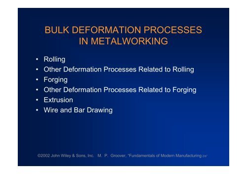
<strong>BULK</strong> <strong>DEFORMATION</strong> <strong>PROCESSES</strong><strong>IN</strong> METALWORK<strong>IN</strong>G•Rolling•Other Deformation Processes Related to Rolling•Forging•Other Deformation Processes Related to Forging•Extrusion•Wire and Bar Drawing©2002 John Wiley & Sons, Inc. M. P. Groover, “Fundamentals of Modern Manufacturing 2/e”
Bulk DeformationMetal forming operations which cause significant shapechange by deformation in metal parts whose initialform is bulk rather than sheet•Starting forms: cylindrical bars and billets, rectangularbillets and slabs, and similar shapes•These processes work by stressing metal sufficientlyto cause plastic flow into desired shape•Performed as cold, warm, and hot working operations©2002 John Wiley & Sons, Inc. M. P. Groover, “Fundamentals of Modern Manufacturing 2/e”
Importance of Bulk Deformation•In hot working, significant shape change can beaccomplished•In cold working, strength can be increased duringshape change•Little or no waste - some operations are near netshape or net shape processesThe parts require little or no subsequentmachining©2002 John Wiley & Sons, Inc. M. P. Groover, “Fundamentals of Modern Manufacturing 2/e”
Four Basic Bulk Deformation Processes1. Rolling –slab or plate is squeezed betweenopposing rolls2. Forging –work is squeezed and shaped betweenbetween opposing dies3. Extrusion –work is squeezed through a die opening,thereby taking the shape of the opening4. Wire and bar drawing –diameter of wire or bar isreduced by pulling it through a die opening©2002 John Wiley & Sons, Inc. M. P. Groover, “Fundamentals of Modern Manufacturing 2/e”
RollingDeformation process in which work thickness is reducedby compressive forces exerted by two opposing rollsFigure 19.1 - The rolling process (specifically, flat rolling)©2002 John Wiley & Sons, Inc. M. P. Groover, “Fundamentals of Modern Manufacturing 2/e”
The RollsThe rotating rolls perform two main functions:•Pull the work into the gap between them by frictionbetween workpart and rolls•Simultaneously squeeze the work to reduce crosssection©2002 John Wiley & Sons, Inc. M. P. Groover, “Fundamentals of Modern Manufacturing 2/e”
•By geometry of work:Types of RollingFlat rolling - used to reduce thickness of arectangular cross-sectionShape rolling - a square cross-section is formedinto a shape such as an I-beam•By temperature of work:Hot Rolling –most common due to the largeamount of deformation requiredCold rolling –produces finished sheet and platestock©2002 John Wiley & Sons, Inc. M. P. Groover, “Fundamentals of Modern Manufacturing 2/e”
Figure 19.2 - Some of the steel products made in a rolling mill©2002 John Wiley & Sons, Inc. M. P. Groover, “Fundamentals of Modern Manufacturing 2/e”
Figure 19.3 - Side view of flat rolling, indicating before and afterthicknesses, work velocities, angle of contact with rolls, andother features©2002 John Wiley & Sons, Inc. M. P. Groover, “Fundamentals of Modern Manufacturing 2/e”
Flat Rolling –TerminologyDraft = amount of thickness reductiondto t fwhere d = draft; t o = starting thickness; and t f = finalthickness©2002 John Wiley & Sons, Inc. M. P. Groover, “Fundamentals of Modern Manufacturing 2/e”
Flat Rolling –TerminologyReduction = draft expressed as a fraction of startingstock thickness:dr t owhere r = reduction©2002 John Wiley & Sons, Inc. M. P. Groover, “Fundamentals of Modern Manufacturing 2/e”
Shape RollingWork is deformed into a contoured cross-section ratherthan flat (rectangular)•Accomplished by passing work through rolls thathave the reverse of desired shape•Products include:Construction shapes such as I-beams, L-beams,and U-channelsRails for railroad tracksRound and square bars and rods©2002 John Wiley & Sons, Inc. M. P. Groover, “Fundamentals of Modern Manufacturing 2/e”
Figure 19.5 - Arolling mill for hotflat rolling; thesteel plate isseen as theglowing stripextendingdiagonally fromthe lower leftcorner(photo courtesyof BethlehemSteel Company)©2002 John Wiley & Sons, Inc. M. P. Groover, “Fundamentals of Modern Manufacturing 2/e”
Rolling Mills•Equipment is massive and expensive•Rolling mill configurations:Two-high –two opposing large diameter rollsThree-high –work passes through both directionsFour-high –backing rolls support smaller workrollsCluster mill –multiple backing rolls on smaller rollsTandem rolling mill –sequence of two-high mills©2002 John Wiley & Sons, Inc. M. P. Groover, “Fundamentals of Modern Manufacturing 2/e”
Figure 19.6 - Various configurations of rolling mills:(a) 2-high rolling mill©2002 John Wiley & Sons, Inc. M. P. Groover, “Fundamentals of Modern Manufacturing 2/e”
Figure 19.6 - Various configurations of rolling mills:(b) 3-high rolling mill©2002 John Wiley & Sons, Inc. M. P. Groover, “Fundamentals of Modern Manufacturing 2/e”
Figure 19.6 - Various configurations of rolling mills:(c) four-high rolling mill©2002 John Wiley & Sons, Inc. M. P. Groover, “Fundamentals of Modern Manufacturing 2/e”
Cluster MillMultiple backing rolls allow even smaller roll diametersFigure 19 6 - Various configurations of rolling mills: (d) cluster mill©2002 John Wiley & Sons, Inc. M. P. Groover, “Fundamentals of Modern Manufacturing 2/e”
Tandem Rolling MillA series of rolling stands in sequenceFigure 19.6 - Various configurations of rolling mills:(e) tandem rolling mill©2002 John Wiley & Sons, Inc. M. P. Groover, “Fundamentals of Modern Manufacturing 2/e”
Thread RollingBulk deformation process used to form threads oncylindrical parts by rolling them between two dies•Most important commercial process for massproducing bolts and screws•Performed by cold working in thread rolling machines•Advantages over thread cutting (machining):Higher production ratesBetter material utilizationStronger threads due to work hardeningBetter fatigue resistance due to compressivestresses introduced by rolling©2002 John Wiley & Sons, Inc. M. P. Groover, “Fundamentals of Modern Manufacturing 2/e”
Figure 19.7 - Thread rolling with flat dies:(1) start of cycle, and (2) end of cycle©2002 John Wiley & Sons, Inc. M. P. Groover, “Fundamentals of Modern Manufacturing 2/e”
Ring RollingDeformation process in which a thick-walled ring ofsmaller diameter is rolled into a thin-walled ring oflarger diameter•As thick-walled ring is compressed, deformed metalelongates, causing diameter of ring to be enlarged•Hot working process for large rings and cold workingprocess for smaller rings•Applications: ball and roller bearing races, steel tiresfor railroad wheels, and rings for pipes, pressurevessels, and rotating machinery•Advantages: material savings, ideal grain orientation,strengthening through cold working©2002 John Wiley & Sons, Inc. M. P. Groover, “Fundamentals of Modern Manufacturing 2/e”
Figure 19.8 - Ring rolling used to reduce the wall thickness andincrease the diameter of a ring:(1) start, and (2) completion of process©2002 John Wiley & Sons, Inc. M. P. Groover, “Fundamentals of Modern Manufacturing 2/e”
ForgingDeformation process in which work is compressedbetween two dies•Oldest of the metal forming operations, dating fromabout 5000 B C•Components: engine crankshafts, connecting rods,gears, aircraft structural components, jet engineturbine parts•In addition, basic metals industries use forging toestablish basic form of large components that aresubsequently machined to final shape and size©2002 John Wiley & Sons, Inc. M. P. Groover, “Fundamentals of Modern Manufacturing 2/e”
Classification of Forging Operations•Cold vs. hot forging:Hot or warm forging –most common, due to thesignificant deformation and the need to reducestrength and increase ductility of work metalCold forging - advantage is increased strength thatresults from strain hardening•Impact vs. press forging:Forge hammer - applies an impact loadForge press - applies gradual pressure©2002 John Wiley & Sons, Inc. M. P. Groover, “Fundamentals of Modern Manufacturing 2/e”
Types of Forging Dies•Open-die forging - work is compressed between twoflat dies, allowing metal to flow laterally withoutconstraint•Impression-die forging - die surfaces contain a cavityor impression that is imparted to workpart, thusconstraining metal flow - flash is created•Flashless forging - workpart is completelyconstrained in die and no excess flash is produced©2002 John Wiley & Sons, Inc. M. P. Groover, “Fundamentals of Modern Manufacturing 2/e”
Figure 19.10 - Three types of forging: (a) open-die forging©2002 John Wiley & Sons, Inc. M. P. Groover, “Fundamentals of Modern Manufacturing 2/e”
Figure 19.10 - Three types of forging (b) impression-die forging©2002 John Wiley & Sons, Inc. M. P. Groover, “Fundamentals of Modern Manufacturing 2/e”
Figure 19.10 - Three types of forging (c) flashless forging©2002 John Wiley & Sons, Inc. M. P. Groover, “Fundamentals of Modern Manufacturing 2/e”
Open-Die ForgingCompression of workpart with cylindrical cross-sectionbetween two flat dies•Similar to compression test•Deformation operation reduces height and increasesdiameter of work•Common names include upsetting or upset forging©2002 John Wiley & Sons, Inc. M. P. Groover, “Fundamentals of Modern Manufacturing 2/e”
Open-Die Forging with No FrictionIf no friction occurs between work and die surfaces,then homogeneous deformation occurs, so that radialflow is uniform throughout workpart height and truestrain is given by:ln h ohwhere h o = starting height; and h = height at somepoint during compression•At h = final value h f , true strain is maximum value©2002 John Wiley & Sons, Inc. M. P. Groover, “Fundamentals of Modern Manufacturing 2/e”
Figure 19.11 - Homogeneous deformation of a cylindrical workpartunder ideal conditions in an open-die forging operation:(1) start of process with workpiece at its original length anddiameter, (2) partial compression, and (3) final size©2002 John Wiley & Sons, Inc. M. P. Groover, “Fundamentals of Modern Manufacturing 2/e”
Open-Die Forging with Friction•Friction between work and die surfaces constrainslateral flow of work, resulting in barreling effect•In hot open-die forging, effect is even morepronounced due to heat transfer at and near diesurfaces, which cools the metal and increases itsresistance to deformation©2002 John Wiley & Sons, Inc. M. P. Groover, “Fundamentals of Modern Manufacturing 2/e”
Figure 19.12 - Actual deformation of a cylindrical workpart inopen-die forging, showing pronounced barreling:(1) start of process, (2) partial deformation, and (3) final shape©2002 John Wiley & Sons, Inc. M. P. Groover, “Fundamentals of Modern Manufacturing 2/e”
Impression-Die ForgingCompression of workpart by dies with inverse of desiredpart shape•Flash is formed by metal that flows beyond die cavityinto small gap between die plates•Flash must be later trimmed from part, but it servesan important function during compression:As flash forms, friction resists continued metal flowinto gap, constraining material to fill die cavityIn hot forging, metal flow is further restricted bycooling against die plates©2002 John Wiley & Sons, Inc. M. P. Groover, “Fundamentals of Modern Manufacturing 2/e”
Figure 19.15 - Sequence in impression-die forging:(1) just prior to initial contact with raw workpiece,(2) partial compression, and(3) final die closure, causing flash to form in gap between die plates©2002 John Wiley & Sons, Inc. M. P. Groover, “Fundamentals of Modern Manufacturing 2/e”
Impression-Die Forging Practice•Several forming steps often required, with separatedie cavities for each stepBeginning steps redistribute metal for moreuniform deformation and desired metallurgicalstructure in subsequent stepsFinal steps bring the part to its final geometryImpression-die forging is often performedmanually by skilled operator under adverseconditions©2002 John Wiley & Sons, Inc. M. P. Groover, “Fundamentals of Modern Manufacturing 2/e”
Impression-Die ForgingAdvantages and Limitations•Advantages compared to machining from solid stock:Higher production ratesConservation of metal (less waste)Greater strengthFavorable grain orientation in the metal•Limitations:Not capable of close tolerancesMachining often required to achieve accuraciesand features needed, such as holes, threads, andmating surfaces that fit with other components©2002 John Wiley & Sons, Inc. M. P. Groover, “Fundamentals of Modern Manufacturing 2/e”
Flashless ForgingCompression of work in punch and die tooling whosecavity does allow for flash•Starting workpart volume must equal die cavityvolume within very close tolerance•Process control more demanding than impression-dieforging•Best suited to part geometries that are simple andsymmetrical•Often classified as a precision forging process©2002 John Wiley & Sons, Inc. M. P. Groover, “Fundamentals of Modern Manufacturing 2/e”
Figure 19.18 - Flashless forging:(1) just before initial contact with workpiece,(2) partial compression, and(3) final punch and die closure©2002 John Wiley & Sons, Inc. M. P. Groover, “Fundamentals of Modern Manufacturing 2/e”
Forging Hammers (Drop Hammers)•Apply an impact load against workpart - two types:Gravity drop hammers - impact energy from fallingweight of a heavy ramPower drop hammers - accelerate the ram bypressurized air or steam•Disadvantage: impact energy transmitted throughanvil into floor of building•Most commonly used for impression-die forging©2002 John Wiley & Sons, Inc. M. P. Groover, “Fundamentals of Modern Manufacturing 2/e”
Figure 19.20 - Drop forging hammer, fed by conveyor and heatingunits at the right of the scene(photo courtesy of Chambersburg Engineering Company)©2002 John Wiley & Sons, Inc. M. P. Groover, “Fundamentals of Modern Manufacturing 2/e”
Figure 19.21 - Diagram showing details of a drop hammer forimpression-die forging©2002 John Wiley & Sons, Inc. M. P. Groover, “Fundamentals of Modern Manufacturing 2/e”
Forging Presses•Apply gradual pressure to accomplish compressionoperation - types:Mechanical presses - converts rotation of drivemotor into linear motion of ramHydraulic presses - hydraulic piston actuates ramScrew presses - screw mechanism drives ram©2002 John Wiley & Sons, Inc. M. P. Groover, “Fundamentals of Modern Manufacturing 2/e”
Upsetting and HeadingForging process used to form heads on nails, bolts, andsimilar hardware products•More parts produced by upsetting than any otherforging operation•Performed cold, warm, or hot on machines calledheaders or formers•Wire or bar stock is fed into machine, end is headed,then piece is cut to length•For bolts and screws, thread rolling is then used toform threads©2002 John Wiley & Sons, Inc. M. P. Groover, “Fundamentals of Modern Manufacturing 2/e”
Figure 19.23 - An upset forging operation to form a head on a boltor similar hardware item The cycle consists of:(1) wire stock is fed to the stop(2) gripping dies close on the stock and the stop is retracted(3) punch moves forward(4) bottoms to form the head©2002 John Wiley & Sons, Inc. M. P. Groover, “Fundamentals of Modern Manufacturing 2/e”
Figure 19.24 - Examples of heading (upset forging) operations:(a) heading a nail using open dies(b) round head formed by punch(c) and (d) two common head styles for screws formed by die(e) carriage bolt head formed by punch and die©2002 John Wiley & Sons, Inc. M. P. Groover, “Fundamentals of Modern Manufacturing 2/e”
SwagingAccomplished by rotating dies that hammer a workpieceradially inward to taper it as the piece is fed into thedies•Used to reduce diameter of tube or solid rod stock•Mandrel sometimes required to control shape andsize of internal diameter of tubular parts©2002 John Wiley & Sons, Inc. M. P. Groover, “Fundamentals of Modern Manufacturing 2/e”
Figure 19.25 - Swaging process to reduce solid rod stock; the diesrotate as they hammer the work In radial forging, the workpiecerotates while the dies remain in a fixed orientation as theyhammer the work©2002 John Wiley & Sons, Inc. M. P. Groover, “Fundamentals of Modern Manufacturing 2/e”
TrimmingCutting operation to remove flash from workpart inimpression-die forging•Usually done while work is still hot, so a separatetrimming press is included at the forging station•Trimming can also be done by alternative methods,such as grinding or sawing©2002 John Wiley & Sons, Inc. M. P. Groover, “Fundamentals of Modern Manufacturing 2/e”
Figure 19.30 - Trimming operation (shearing process) to removethe flash after impression-die forging©2002 John Wiley & Sons, Inc. M. P. Groover, “Fundamentals of Modern Manufacturing 2/e”
ExtrusionCompression forming process in which the work metalis forced to flow through a die opening to produce adesired cross-sectional shape•Process is similar to squeezing toothpaste out of atoothpaste tube•In general, extrusion is used to produce long parts ofuniform cross-sections•Two basic types of extrusion:Direct extrusionIndirect extrusion©2002 John Wiley & Sons, Inc. M. P. Groover, “Fundamentals of Modern Manufacturing 2/e”
Figure 19.31 - Direct extrusion©2002 John Wiley & Sons, Inc. M. P. Groover, “Fundamentals of Modern Manufacturing 2/e”
Comments on Direct Extrusion•Also called forward extrusion•As ram approaches die opening, a small portion ofbillet remains that cannot be forced through dieopening•This extra portion, called the butt, must be separatedfrom extruded product by cutting it just beyond thedie exit•Starting billet cross section usually round, but finalshape is determined by die opening©2002 John Wiley & Sons, Inc. M. P. Groover, “Fundamentals of Modern Manufacturing 2/e”
Figure 19.32 - (a) Direct extrusion to produce a hollow or semi-hollowcross-section; (b) hollow and (c) semi-hollow cross- sections©2002 John Wiley & Sons, Inc. M. P. Groover, “Fundamentals of Modern Manufacturing 2/e”
Figure 19.33 - Indirect extrusion to produce(a) a solid cross-section and (b) a hollow cross-section©2002 John Wiley & Sons, Inc. M. P. Groover, “Fundamentals of Modern Manufacturing 2/e”
Comments on Indirect Extrusion•Also called backward extrusion and reverse extrusion•Limitations of indirect extrusion are imposed by thelower rigidity of hollow ram and difficulty in supportingextruded product as it exits die©2002 John Wiley & Sons, Inc. M. P. Groover, “Fundamentals of Modern Manufacturing 2/e”
General Advantages of Extrusion•Variety of shapes possible, especially in hot extrusionLimitation: part cross-section must be uniformthroughout length•Grain structure and strength enhanced in cold andwarm extrusion•Close tolerances possible, especially in coldextrusion•In some operations, little or no waste of material©2002 John Wiley & Sons, Inc. M. P. Groover, “Fundamentals of Modern Manufacturing 2/e”
Hot vs. Cold Extrusion•Hot extrusion - prior heating of billet to above itsrecrystallization temperatureThis reduces strength and increases ductility ofthe metal, permitting more size reductions andmore complex shapes•Cold extrusion - generally used to produce discretepartsThe term impact extrusion is used to indicate highspeed cold extrusion©2002 John Wiley & Sons, Inc. M. P. Groover, “Fundamentals of Modern Manufacturing 2/e”
Extrusion RatioAlso called the reduction ratio, it is defined asArxAofwhere r x = extrusion ratio; A o = cross-sectional area ofthe starting billet; and A f = final cross-sectional areaof the extruded section•Applies to both direct and indirect extrusion©2002 John Wiley & Sons, Inc. M. P. Groover, “Fundamentals of Modern Manufacturing 2/e”
Figure 19.36 -(a) Definition of die angle in direct extrusion;(b) effect of die angle on ram force©2002 John Wiley & Sons, Inc. M. P. Groover, “Fundamentals of Modern Manufacturing 2/e”
Comments on Die Angle•Low die angle - surface area is large, leading toincreased friction at die-billet interfaceHigher friction results in larger ram force•Large die angle - more turbulence in metal flowduring reductionTurbulence increases ram force required•Optimum angle depends on work material, billettemperature, and lubrication©2002 John Wiley & Sons, Inc. M. P. Groover, “Fundamentals of Modern Manufacturing 2/e”
Comments on Orifice Shapeof Extrusion Die•Simplest cross section shape = circular die orifice•Shape of die orifice affects ram pressure•As cross-section becomes more complex, higherpressure and greater force are required©2002 John Wiley & Sons, Inc. M. P. Groover, “Fundamentals of Modern Manufacturing 2/e”
Figure 19.37 - A complex extruded cross-section for a heat sink(photo courtesy of Aluminum Company of America)©2002 John Wiley & Sons, Inc. M. P. Groover, “Fundamentals of Modern Manufacturing 2/e”
Extrusion Presses•Either horizontal or verticalHorizontal more common•Extrusion presses - usually hydraulically driven,which is especially suited to semi-continuous directextrusion of long sections•Mechanical drives - often used for cold extrusion ofindividual parts©2002 John Wiley & Sons, Inc. M. P. Groover, “Fundamentals of Modern Manufacturing 2/e”
Wire and Bar DrawingCross-section of a bar, rod, or wire is reduced by pullingit through a die opening•Similar to extrusion except work is pulled through diein drawing (it is pushed through in extrusion)•Although drawing applies tensile stress, compressionalso plays a significant role since metal is squeezedas it passes through die opening©2002 John Wiley & Sons, Inc. M. P. Groover, “Fundamentals of Modern Manufacturing 2/e”
Figure 19.41 - Drawing of bar, rod, or wire©2002 John Wiley & Sons, Inc. M. P. Groover, “Fundamentals of Modern Manufacturing 2/e”
Area Reduction in DrawingChange in size of work is usually given by areareduction:rAoAAofwhere r = area reduction in drawing; A o = original areaof work; and A r = final work©2002 John Wiley & Sons, Inc. M. P. Groover, “Fundamentals of Modern Manufacturing 2/e”
Wire Drawing vs. Bar Drawing•Difference between bar drawing and wire drawing isstock sizeBar drawing - large diameter bar and rod stockWire drawing - small diameter stock - wire sizesdown to 0.03 mm (0.001 in.) are possible•Although the mechanics are the same, the methods,equipment, and even terminology are different©2002 John Wiley & Sons, Inc. M. P. Groover, “Fundamentals of Modern Manufacturing 2/e”
Drawing Practice and Products•Drawing practice:Usually performed as cold workingMost frequently used for round cross-sections•Products:Wire: electrical wire; wire stock for fences, coathangers, and shopping cartsRod stock for nails, screws, rivets, and springsBar stock: metal bars for machining, forging, andother processes©2002 John Wiley & Sons, Inc. M. P. Groover, “Fundamentals of Modern Manufacturing 2/e”
Bar Drawing•Accomplished as a single-draft operation - the stockis pulled through one die opening•Beginning stock has large diameter and is a straightcylinder•This necessitates a batch type operation©2002 John Wiley & Sons, Inc. M. P. Groover, “Fundamentals of Modern Manufacturing 2/e”
Figure 19.42 - Hydraulically operated draw benchfor drawing metal bars©2002 John Wiley & Sons, Inc. M. P. Groover, “Fundamentals of Modern Manufacturing 2/e”
Wire Drawing•Continuous drawing machines consisting of multipledraw dies (typically 4 to 12) separated byaccumulating drumsEach drum (capstan) provides proper force todraw wire stock through upstream dieEach die provides a small reduction, so desiredtotal reduction is achieved by the seriesAnnealing sometimes required between dies©2002 John Wiley & Sons, Inc. M. P. Groover, “Fundamentals of Modern Manufacturing 2/e”
Figure 19.43 - Continuous drawing of wire©2002 John Wiley & Sons, Inc. M. P. Groover, “Fundamentals of Modern Manufacturing 2/e”
Features of a Draw Die•Entry region - funnels lubricant into the die to preventscoring of work and die•Approach - cone-shaped region where drawingoccurs•Bearing surface - determines final stock size•Back relief - exit zone - provided with a back reliefangle (half-angle) of about 30•Die materials: tool steels or cemented carbides©2002 John Wiley & Sons, Inc. M. P. Groover, “Fundamentals of Modern Manufacturing 2/e”
Figure 19.44 - Draw die for drawing of round rod or wire©2002 John Wiley & Sons, Inc. M. P. Groover, “Fundamentals of Modern Manufacturing 2/e”
Preparation of the Work forWire or Bar Drawing•Annealing –to increase ductility of stock•Cleaning - to prevent damage to work surface anddraw die•Pointing –to reduce diameter of starting end to allowinsertion through draw die©2002 John Wiley & Sons, Inc. M. P. Groover, “Fundamentals of Modern Manufacturing 2/e”