MICRONAILT Distal Radius Implant .pdf - Osteosyntese
MICRONAILT Distal Radius Implant .pdf - Osteosyntese
MICRONAILT Distal Radius Implant .pdf - Osteosyntese

Create successful ePaper yourself
Turn your PDF publications into a flip-book with our unique Google optimized e-Paper software.
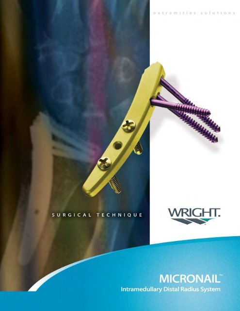
MICRONAILIntramedullary <strong>Distal</strong> <strong>Radius</strong> System
MICRONAIL intramedullary distalradius systemsurgical techniqueSURGEON DESIGN TEAMMARK WARBURTON, MDJOHN CAPO, MDVIRAK TAN, MDProper surgical procedures and techniques are the responsibility of the medicalprofessional. Each surgeon must evaluate the appropriateness of the procedureused based on personal medical training and experience. Wright cannotrecommend a particular surgical technique suitable for all patients.
MICRONAIL INTRAMEDULLARY DISTAL RADIUS SYSTEMMICRONAIL INTRAMEDULLARY DISTAL RADIUS SYSTEMas described byMark Warburton, MD; John Capo, MD; and Virak Tan, MDNOTE | For more information about the MICRONAIL System and the recommendedsurgical technique, please refer to the surgical and animation videos.PATIENT SELECTIONThe MICRONAIL Intramedullary <strong>Distal</strong> <strong>Radius</strong> System is primarily designedfor minimally-invasive fixation of extra-articular fractures and simple intraarticularfractures of the distal radius. It is particularly useful for treatment ofpatients who have failed non-operative treatment of such fractures and inosteotomies.IMPLANT/DESIGN FEATURES• Titanium alloy (Ti-6Al-4V ELI)• Universal configuration for left and right wrists• Available in four anatomical sizes• Zero profileA 2.0mm hole located in the proximal body allows fortemporary fixation using a K-wire duringThree 2.5mm fixed-angle locking screws buttress the subchondralplate and secure the distal fracture fragment(s)to the nail. The distal screws are anatomically configuredto approximate the radial inclination while thevolar-dorsal angle divergence provides stable, threepointfixation. The distal screw heads are completelyrecessed below the surface of the nail.fracture reduction.Two 2.7mm self-tapping, bi-cortical, proximal screwsresist shortening and angulation of the distal fracturefragment. The screws are placed through the proximalbody of the nail while the low-profile head rests on thedorsal surface of the bone.one
MICRONAIL INTRAMEDULLARY DISTAL RADIUS SYSTEMINITIAL REDUCTIONAchieve provisional angular (dorsal/volar) reduction prior to initiating theMICRONAIL procedure. To stabilize reduction, temporarily place a 0.062"K-wire (P/N 59410625) dorsal to volar | FIGURES 1, 2 along the ulnar cortexof the radius. | FIGURE 3 Length can be adjusted intra-operatively.FIGURE 1 | Optional K-wireFIGURE 3 | Keep K-wire out of broaching path.FIGURE 2 |two
MICRONAIL INTRAMEDULLARY DISTAL RADIUS SYSTEMSURGICAL EXPOSUREMake a 2-3cm longitudinal incision centered over the radial styloid. Bluntlydissect through the subcutaneous tissue. Mobilize any branches of theradial sensory nerve and retract from the surgical field. Dissect down tothe periosteum between the 1st and 2nd dorsal extensor compartments.| FIGURE 62-3cm incisionFIGURE 4 |FIGURE 6 |FIGURE 5 |Altered material reprinted with permission fromThe Journal of Bone and Joint Surgery, Inc.three
MICRONAIL INTRAMEDULLARY DISTAL RADIUS SYSTEMCANAL ENTRYCreate a bolster using two folded towels and place beneath the wrist. Deviatethe wrist ulnarly to gain access to the medullary canal. Insert the StarterAwl (P/N 26949471) through the cortical window and into the medullarycanal until the shoulder of the awl is countersunk beneath the corticalbone. | FIGURES 11, 12 Keep the tip of the starter awl against the radialcortex. | FIGURE 13FIGURE 11 |FIGURE 13 |FIGURE 12 |five
MICRONAIL INTRAMEDULLARY DISTAL RADIUS SYSTEMSubchondralsupportFIGURE 14 |FIGURE 16 | Insert guide wire 2-3mm proximal to articular surface.BROACHINGBroach in a manner similar to a total hip arthroplasty or total shoulder arthroplasty.Gently tap the Broaches (P/N 26949451 through 4) with a smallmallet as needed to advance or remove the broaches. | FIGURE 14 Broachdown the axis of the radius staying parallel with the dorsal surface and closeto the radial cortex creating a rectangular path for the <strong>Implant</strong>.| FIGURE 15Verify proper broach placement by inserting a K-wire through the distal holeof the Broaches. The K-wire should lie just below the subchondral bone.| FIGURE 16FIGURE 15 |SIZINGBroach using progressively larger Broaches until the Broach does not spinwithin the medullary canal (i.e. 2-finger pressure). Select appropriatelysized<strong>Implant</strong> (P/N 59410001 through 4). Down-sizing the <strong>Implant</strong> isrecommended rather than “over-stuffing” the canal. This allows for someability to fine-tune the reduction prior to inserting the proximal screws butdoes not sacrifice permanent stability.six
MICRONAIL INTRAMEDULLARY DISTAL RADIUS SYSTEMAAttach Proximal Targeting GuideBIMPLANT INSERTIONInsert the <strong>Implant</strong> into the medullary canal using the outrigger assembly.| FIGURE 17 Position the Outrigger so the proximal guide is parallel to thedorsal surface of the radius. | FIGURE 18 Verify proper implant placementby inserting a 2.0mm Drill Bit (P/N 26949461) through the most distal holeof the Outrigger. This can be done by hand power. The drill bit should liewithin 3mm of the subchondral bone. | FIGURE 19 Also, verify in lateralview that reduction has been maintained.Attach <strong>Implant</strong>Incorrect Correct IncorrectFIGURE 18 |CAttach Threaded Handle toOutrigger AssemblyFIGURE 17 |SubchondralsupportFIGURE 19 |seven
MICRONAIL INTRAMEDULLARY DISTAL RADIUS SYSTEMFIGURE 20 |BUTTRESS SCREW PLACEMENTDrill the hole for the most distal Buttress Screw. This may be done by handpower using the Driver Handle. | FIGURE 20 Use the laser etchings on thedrill bit to determine proper screw length paying careful attention to stayout of the DRUJ. The most common screw lengths are 20-24mm. Use theScrewdriver Handle (P/N 44112009) and self-retaining CruciformScrewdriver (P/N 26949470) to remove the appropriate size 2.5mm ButtressScrew (P/N 59412516 through 28) from the screw caddy. A firm stop will befelt when the Buttress Screw is locked into the implant.If position and length of the most distal Buttress Screw are satisfactory,| FIGURE 21 the steps are repeated for the two remaining Buttress Screws.Care should be taken to retract any soft tissues. If necessary, the initialincision can be enlarged.The Buttress Screws should now be positioned in a divergent fashion and thedistal fragment should now be securely captured. | FIGURES 22, 23FIGURE 21 |FIGURE 22 |FIGURE 23 |eight
MICRONAIL INTRAMEDULLARY DISTAL RADIUS SYSTEMPROXIMAL EXPOSUREUsing the Proximal Targeting Guide as a template, mark a 2-3cm line on theskin of the patient that spans the two screw holes. Temporarily removethe Proximal Targeting Guide and make the skin incision. | FIGURE 24Retract the extensor tendons and bluntly dissect the underlying soft tissueto the surface of the radius. | FIGURE 25 Reattach the ProximalTargeting Guide.FIGURE 24 |FIGURE 25 |nine
MICRONAIL INTRAMEDULLARY DISTAL RADIUS SYSTEMFINAL REDUCTIONPrior to securing the implant proximally, final reduction can be performed.Any provisional K-wires that remain should be removed. Restore length asneeded by manipulating the Threaded Handle. If necessary, temporarilymaintain reduction by inserting a K-wire through one of the K-wire holeson the Proximal Targeting Guide. | FIGURES 26, 27FIGURE 26 |CORTICAL SCREW PLACEMENTInsert the three nested proximal guides (Obturator, Drill Guide and TissueProtector) into the Proximal Targeting Guide | FIGURE 28 until theycome to rest on the cortical bone surface. | FIGURE 29 Remove theObturator (P/N 26949483) to drill the hole for the Cortical Screw.FIGURE 27 |ObturatorDrill guideTissue protectorFIGURE 29 |FIGURE 28 |ten
measuring edgeDrill through the first (dorsal) cortex and through the implant until the drillbit reaches the second (volar) cortex. Determine screw length by notingwhich laser marking on the drill bit is closest to the measuring edge of theTissue Protector (P/N 26949480). | FIGURE 30 Add 2mm as necessary.Complete the bicortical hole by drilling through the second (volar) cortex.Remove the Drill Guide (P/N 26949472) and insert the Screw Guide (P/N26949446). Insert the appropriate size screw and tighten until the head isflush with the bone. Repeat these steps for the remaining Cortical Screw.Cortical Screws are typically 12-14cm long.FIGURE 30 |CLOSURERemove the Outrigger Assembly by removing the provisional K-wire andloosening the distal locking knob.Take the forearm and wrist through a full ROM to ensure that there are nopenetrating screws in the DRUJ or radiocarpal joint and check overallfracture stability. Irrigate the surgical site and perform standard skinclosure.POSTOPERATIVE TREATMENTPlace the wrist in a splint for 7-10 days. Start finger motion immediately post-op.At the first post-op visit, remove the splint and progress therapy.FIGURE 31 | Final lateral view of MICRONAIL SystemFIGURE 32 | Final AP view of MICRONAIL Systemeleven
MICRONAIL INTRAMEDULLARY DISTAL RADIUS SYSTEMAPPENDIX A | ORDERING INFORMATIONMICRONAIL INTRAMEDULLARY DISTAL RADIUS SYSTEMKIT # CATALOG # DESCRIPTION KIT QTY5941KITA 59410001 SIZE 1 DISTAL RADIUS IMPLANT 259410002 SIZE 2 DISTAL RADIUS IMPLANT 259410003 SIZE 3 DISTAL RADIUS IMPLANT 259410004 SIZE 4 DISTAL RADIUS IMPLANT 259412710 2.7 X 10MM CORTICAL SCREW 459412712 2.7 X 12MM CORTICAL SCREW 459412714 2.7 X 14MM CORTICAL SCREW 459412716 2.7 X 16MM CORTICAL SCREW 459412718 2.7 X 18MM CORTICAL SCREW 459412720 2.7 X 20MM CORTICAL SCREW 459412516 2.7 X 16MM BUTTRESS SCREW 459412518 2.5 X 18MM BUTTRESS SCREW 459412520 2.5 X 20MM BUTTRESS SCREW 459412522 2.5 X 22MM BUTTRESS SCREW 459412524 2.5 X 24MM BUTTRESS SCREW 459412526 2.5 X 26MM BUTTRESS SCREW 459412528 2.5 X 28MM BUTTRESS SCREW 426949461 MICRONAIL 2.0MM DRILL BIT 259410625 .062 X 5" K-WIRE, STERILE 4TOTAL IMPLANTS 66KIT # CATALOG # DESCRIPTION KIT QTY5941KIT1 26949440 MICRONAIL OUTRIGGER LEFT 126949441 MICRONAIL OUTRIGGER RIGHT 126949536 MICRONAIL THREADED HANDLE 126949474 MICRONAIL 2.7MM CORTICAL SCREW TAP 126949470 MICRONAIL CRUCIFORM SCREWDRIVER 226949468 MICRONAIL 6.1MM CANNULATED STARTER DRILL 144112009 CANNULATED SCREWDRIVER HANDLE 126949462 MICRONAIL STARTER DRILL / K-WIRE GUIDE 126949471 MICRONAIL STARTER AWL 126949451 MICRONAIL BROACH SIZE 1 126949452 MICRONAIL BROACH SIZE 2 126949453 MICRONAIL BROACH SIZE 3 126949454 MICRONAIL BROACH SIZE 4 126948001 MICRONAIL SMOOTH TRIAL SIZE 1 126948002 MICRONAIL SMOOTH TRIAL SIZE 2 126948003 MICRONAIL SMOOTH TRIAL SIZE 3 126948004 MICRONAIL SMOOTH TRIAL SIZE 4 126949442 MICRONAIL PROXIMAL TARGETING GUIDE SIZE 1 126949443 MICRONAIL PROXIMAL TARGETING GUIDE SIZE 2 126949444 MICRONAIL PROXIMAL TARGETING GUIDE SIZE 3 126949445 MICRONAIL PROXIMAL TARGETING GUIDE SIZE 4 126949446 MICRONAIL PROXIMAL SCREW GUIDE 126949472 MICRONAIL PROXIMAL DRILL GUIDE 126949480 MICRONAIL PROXIMAL TISSUE PROTECTOR 126949483 MICRONAIL PROXIMAL DRILL GUIDE OBTURATOR 126948010 MICRONAIL SLAPHAMMER 126949473 MICRONAIL SCREW LENGTH GAUGE 126948020 MICRONAIL REMOVAL ADAPTER 126949000 MICRONAIL INSTRUMENT TRAY 1TOTAL INSTRUMENTS 30TOTAL 965941202S MICRONAIL IN CLEAR RADIUS 1twelve
APPENDIX B | INSTRUMENTATIONTOP TRAYIMPLANTSDRIVER HANDLESTARTERDRILLGUIDESTARTER DRILLREMOVABLE SCREW CADDYDRILL BITBOTTOM TRAYBROACHOUTRIGGER HANDLESTARTER AWLTISSUEPROTECTORPROXIMAL GUIDESDRILL GUIDEOBTURATORSCREW GUIDEOUTRIGGERthirteen
ADDITIONALproductsSHORT WORKING TIME FORMULA84XS-0404MICRO MIIG® STAT4CCProcedure Kit for Graftingwith Fixation HardwareWright Medical Technology, Inc.5677 Airline RoadArlington, TN 38002901.867.9971 phone800.238.7188 toll-freewww.wmt.comWright Cremascoli Ortho SAZone Industrielle la FarlecleRue Pasteur BP 22283089 Toulon Cedex 09France011.33.49.408.7788 phoneTrademarks and ®Registered marks of Wright Medical Technology, Inc.Covered by one or more of the following US Patents: 6,527,775. Patents pending.Incorporates technology licensed from Mark Warburton, MD.©2005 Wright Medical Technology. Inc. All Rights Reserved. SO 286-1204 Rev. 07.05