Digital Earth Resistance Tester
Digital Earth Resistance Tester
Digital Earth Resistance Tester

You also want an ePaper? Increase the reach of your titles
YUMPU automatically turns print PDFs into web optimized ePapers that Google loves.
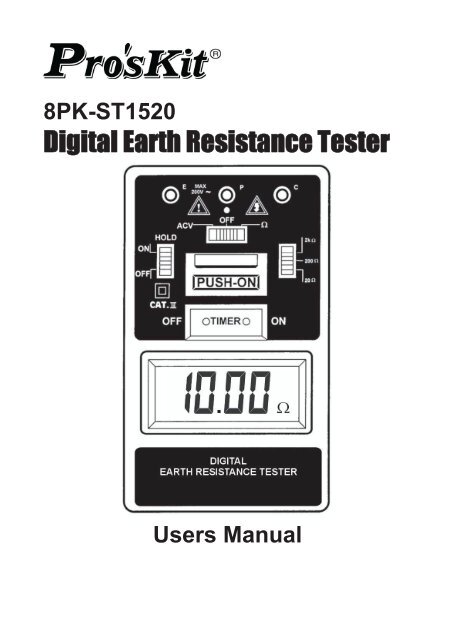
8PK-ST1520<strong>Digital</strong> <strong>Earth</strong> <strong>Resistance</strong> <strong>Tester</strong>Users Manual
Index1.INTRODUCTION ............................2.SAFETY NOTES.............................3.FATURES........................................4.SPECIFICATIONS..............................5.LAYOUT...........................................6.MEASURING METHODS.................7.MAINTENANCE................................Page123456-781.INTRODUCTIONThis meter has been designed and testedaccording to CE safety requirements for ElectronicMeasuring Apparatus, EN61010-1 and other safetystandards. Follow all warnings to ensure safeoperation.●Application:<strong>Earth</strong> <strong>Resistance</strong> <strong>Tester</strong> is used to measure theohms(Ω) of an earth grounding installation forbuildings (residential, office, labs, hospitals),computer server rooms, military installations,cellular sites, radio and cable towers, etc. It isused to determine if the earth (or ground) is agood conductor of electricity.1
●Purpose of <strong>Earth</strong> Grounding:(1)Avoid human and animal electrical shock.(2)Avoid unnecessary property and equipmentdamage.(3)Prevent fire or explosion.(4)Integrate electrical signal to attain properoperation or measuring purpose.(5)Provide a means of dissipation for powersurges caused by lightning strikes, static charges,and other types of electrical interference.2.SAFETY NOTES●Read the following safety information carefullybefore attempting to operate or service the meter.●Use the meter only as specified in this manual.otherwise, the protection provided by this metermay be impaired.●Rated environmental conditions:(1) Indoor Use.(2) Installation Category III.(3) Pollution Degree 2.(4) Altitude up to 2000 meter.(5) Relative humidity 80% max.(6) Ambient temperature 0~40°C.●Observe the International Electrical Symbolslisted Below:2
Meter is protected throughout bydouble insulation or reinforcedinsulationWarning! Risk of electric shock.Caution! Refer to this manualbefore using the Meter.3.FEATURES●Capable of measuring earth voltage.●2mA measuring current permits earth resistancetests without tripping earth leakage currentbreakers in the circuit under test.●Battery operated.●Auto power off function. The timer operates automaticallyabout 3~6 minutes when the "PUSHBUTTON SWITCH" and "TIMER ON BUTTON"are pressed at the same time to keep the testerpower on.●Data hold function.●Small and light weight.●Designed to meet EN61010-1 CAT III 200V.3
4. SPECIFICATIONSMeasurement Ranges <strong>Earth</strong> <strong>Resistance</strong>0-20Ω/0-200Ω/0-2000Ω<strong>Earth</strong> VoltageAccuracy<strong>Earth</strong> <strong>Resistance</strong>ResolutionMeasurement SystemLow Battery IndicationData Hold IndicationOver RangeIndicationOpen CircuitIndicationDisplay LCDPower SourceDimensionsWeightAccessories0-200V AC (40-500Hz)<strong>Earth</strong> <strong>Resistance</strong>± ( 2% rdg+2dgt ) or ± 0.1Ω.which is greater.<strong>Earth</strong> Voltage± ( 1% rdg+2dgt )0-20Ω(0.01Ω)0-200Ω(0.1Ω)0-2000Ω(1Ω)<strong>Earth</strong> resistance by constantcurrentinverter 820Hz approx. 2mA."B" symbol appears on the display"DH" symbol appears on thedisplay"1"(SMD)LED will be unlit3½ digit (2000 counts)1.5V(AA)×6.163(L)×100(W)×50(D)mm480g approx. (battery included)Test leads (AL-36:red-15m yellow-10m green-5m)Auxiliary earth bars.Heavy-duty caseInstruction manualBatteries4
5.LAYOUT(1) "E", "P", "C" Terminal(2) Operation Indicator(3) Data Hold Switch(4) Timer Off Button(5) LCD Display(6) Function Switch(7) Ohm Range Switch(8) PushbuttonOperation(9)Timer On Button5
6.MEASURING METHODSBEFORE PROCEEDING MEASUREMENT, READSAFETY NOTES ON PAGE 2.In proceeding with measurement, if "B"symbol appears on the display, replacewith new batteries.●<strong>Earth</strong> Voltage Measurement:(1) Connection with test leads:Connect green, yellow test leads to instrumentterminals E, P with auxiliary earth bars P1,driven into earth " IN A STRAIGHTLINE".(Fig.1)(2) Set the function switch to ACV position andpress the"PUSH-ON" button and "TIME ON"button at the same time make certain that thevoltage reading is LESS THAN 10V AC,otherwise accurate earth resistancemeasurement may not be made.6
●<strong>Earth</strong> <strong>Resistance</strong> Measurement:(1) Connection with test leads:Connect green, yellow and red test leads toinstrument terminals E, P and C with auxiliaryearth bars P1, C1 driven into earth "IN ASTRAIGHT LINE".(Fig.2)(2) Set the Range Switch to suitable range andset the function switch to Ω position then pressthe PUSH-ON BUTTON and TIME ON BUTTONat the same time and take the reading on thedisplay.WARNING●When none of E, P and C terminalsconnected with test leads, the display shows"1" at Ω function.●Follow the proper connection such as Fig.2,the LED(red) indicator will lit. This proves acorrect current circulation is under its operation.7
7.MAINTENANCE●Battery Replacement:When the symbol "B" appears on the display,replace the batteries as follows :(1) Disconnect the test leads from the instrumentand turn off the power.(2) Use a screwdriver to unscrew the screw onback cover then slide the cover, take out thebatteries and replace with new batteries TypeSUM-3.(3) Place back cover and secure by a screw.●Cleaning and storage:(1) Periodically wipe the case with a damp clothand detergent ; do not use abrasives orsolvents.(2) If the meter is not to be used for periods oflonger than 60 days, remove the batteries andstore them separately.WARNINGTo avoid electrical shock or damage to themeter, do not get water inside the case.8