MAGNA FLAME - System Control Engineering
MAGNA FLAME - System Control Engineering
MAGNA FLAME - System Control Engineering

Create successful ePaper yourself
Turn your PDF publications into a flip-book with our unique Google optimized e-Paper software.
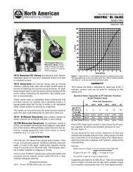
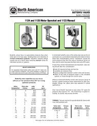
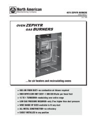
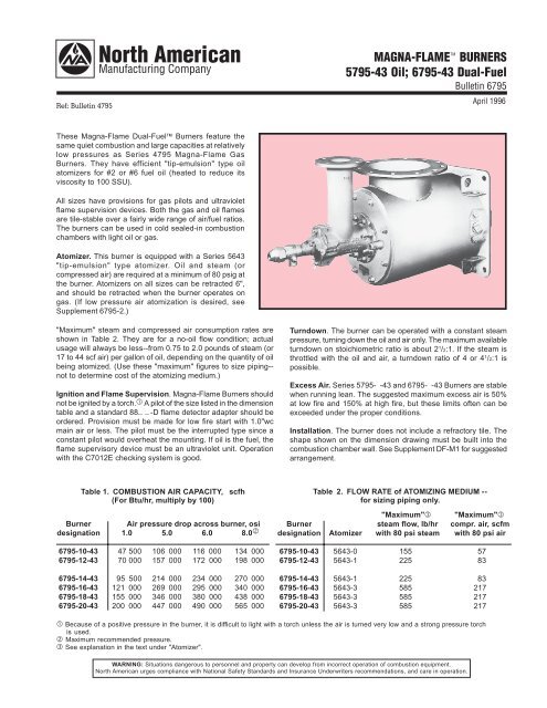
Ref: Bulletin 4795<strong>MAGNA</strong>-<strong>FLAME</strong> TMBURNERS5795-43 Oil; 6795-43 Dual-FuelBulletin 6795April 1996These Magna-Flame Dual-Fuel Burners feature thesame quiet combustion and large capacities at relativelylow pressures as Series 4795 Magna-Flame GasBurners. They have efficient "tip-emulsion" type oilatomizers for #2 or #6 fuel oil (heated to reduce itsviscosity to 100 SSU).All sizes have provisions for gas pilots and ultravioletflame supervision devices. Both the gas and oil flamesare tile-stable over a fairly wide range of air/fuel ratios.The burners can be used in cold sealed-in combustionchambers with light oil or gas.Atomizer. This burner is equipped with a Series 5643"tip-emulsion" type atomizer. Oil and steam (orcompressed air) are required at a minimum of 80 psig atthe burner. Atomizers on all sizes can be retracted 6",and should be retracted when the burner operates ongas. (If low pressure air atomization is desired, seeSupplement 6795-2.)"Maximum" steam and compressed air consumption rates areshown in Table 2. They are for a no-oil flow condition; actualusage will always be less--from 0.75 to 2.0 pounds of steam (or17 to 44 scf air) per gallon of oil, depending on the quantity of oilbeing atomized. (Use these "maximum" figures to size piping--not to determine cost of the atomizing medium.)Ignition and Flame Supervision. Magna-Flame Burners shouldnot be ignited by a torch. A pilot of the size listed in the dimensiontable and a standard 88— —-D flame detector adapter should beordered. Provision must be made for low fire start with 1.0"wcmain air or less. The pilot must be the interrupted type since aconstant pilot would overheat the mounting. If oil is the fuel, theflame supervisory device must be an ultraviolet unit. Operationwith the C7012E checking system is good.Turndown. The burner can be operated with a constant steampressure, turning down the oil and air only. The maximum availableturndown on stoichiometric ratio is about 2 1 /2:1. If the steam isthrottled with the oil and air, a turndown ratio of 4 or 4 1 /2:1 ispossible.Excess Air. Series 5795- -43 and 6795- -43 Burners are stablewhen running lean. The suggested maximum excess air is 50%at low fire and 150% at high fire, but these limits often can beexceeded under the proper conditions.Installation. The burner does not include a refractory tile. Theshape shown on the dimension drawing must be built into thecombustion chamber wall. See Supplement DF-M1 for suggestedarrangement.Table 1. COMBUSTION AIR CAPACITY, scfh(For Btu/hr, multiply by 100)Burner Air pressure drop across burner, osidesignation 1.0 5.0 6.0 8.0 ‚6795-10-43 47 500 106 000 116 000 134 0006795-12-43 70 000 157 000 172 000 198 0006795-14-43 95 500 214 000 234 000 270 0006795-16-43 121 000 269 000 295 000 340 0006795-18-43 155 000 346 000 380 000 438 0006795-20-43 200 000 447 000 490 000 565 000Table 2. FLOW RATE of ATOMIZING MEDIUM --for sizing piping only."Maximum"ƒ "Maximum"ƒBurner steam flow, lb/hr compr. air, scfmdesignation Atomizer with 80 psi steam with 80 psi air6795-10-43 5643-0 155 576795-12-43 5643-1 225 836795-14-43 5643-1 225 836795-16-43 5643-3 585 2176795-18-43 5643-3 585 2176795-20-43 5643-3 585 217 Because of a positive pressure in the burner, it is difficult to light with a torch unless the air is turned very low and a strong pressure torchis used.‚ Maximum recommended pressure.ƒ See explanation in the text under "Atomizer".WARNING: Situations dangerous to personnel and property can develop from incorrect operation of combustion equipment.North American urges compliance with National Safety Standards and Insurance Underwriters recommendations, and care in operation.
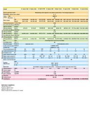
NORTH AMERICAN Mfg. Co.Cleveland, OH 44105-5600 USABulletin 6795, 4-96Page 2DIMENSIONSin inchesHHP BOLT CIRCLEJ BOLT CIRCLEE DIA.4 HOLES5795-43OilJJKK CLEARANCE REQ’D FROM FURNACEWALL TO REMOVE ATOMIZER1/2"H°K DIA.F DIA.G NO. OF HOLESFFL DIA.M NO. OF HOLESA PIPE SIZEAIR INLETB PIPE SIZEGAS INLET Y XRN°Q DIA.2”45°45°1” PIPE TAPFOR <strong>FLAME</strong> DETECTORBBCC PILOT TAPPILOT CONN(REFRACTORYTILE NOTBY NA)SVU6795-43Dual FuelSST SQ.SD PIPE SIZEOIL INLETWZ1" PIPE TAPOBS. PORT CONNS.DDDIA.3° TAPEREEDIA.C PIPE SIZESTEAM INLETGG CLEARANCE REQ’D FROM FURNACEWALL TO REMOVE ATOMIZERMIN. TILE LENGTH6" AA DD†Burnerdimensions in inches and degreesdesignation A B C D E F G H° J K L M N P Q R S T U6795-10 10 4 3/4 3/8 7/8 3/4 8 22 1 /2 7 1 /2 9 1 12 15 14 1 /4 16 1/2 8 18 1 /2 14 3 /46795-12 12 4 1 1/2 1 3/4 8 22 1 /2 7 1 /2 9 1 12 15 17 19 1/2 9 21 14 3 /46795-14 14 6 1 1/2 1 1 /8 7/8 8 22 1 /2 9 1 /2 11 1 1 /8 12 15 18 3 /4 21 1/2 9 1 /2 22 14 3 /46795-16 16 6 1 1 /2 3/4 1 1 /8 7/8 8 22 1 /2 9 1 /2 11 3/4 16 11 1 /4 19 1 /4 21 1 /4 1/2 10 1 /2 24 14 3 /46795-18 18 6 1 1 /2 3/4 1 1 /4 7/8 8 22 1 /2 9 1 /2 11 3/4 16 11 1 /4 21 1 /4 23 1 /4 7/8 12 27 14 3 /46795-20 20 8 1 1 /2 3/4 1 1 /4 7/8 8 22 1 /2 11 3 /4 13 1 /2 3/4 20 9 23 1 /8 25 1 /4 7/8 13 30 14DIMENSIONS SHOWN ARE SUBJECT TO CHANGE. PLEASE OBTAIN CERTIFIED PRINTS FROM NORTH AMERICAN MFG. CO.IF SPACE LIMITATIONS OR OTHER CONSIDERATIONS MAKE EXACT DIMENSION(S) CRITICAL.RecommendedBurner dimensions in inches Pilot Assembly Weight, lbdesignation V W X Y Z AA BB CC DD EE FF GG HH JJ KK designation Oil Dual-Fuel6795-10 11 1 3 /16 12 3 /4 12 7 /8 10 1 /2 41 7 /8 2 3 /4 1 1 /2 11 16 5/8 70 12 1 /4 30 3 /4 54 4014-2-T 270 3106795-12 12 1 /2 2 3 /16 15 14 1 /4 11 46 3 /8 2 3 /4 1 1 /2 12 1 /2 18 5/8 78 13 1 /2 34 5 /8 58 4014-2-T 330 3706795-14 13 1 /2 2 3 /16 18 16 1 /4 12 52 3 /8 2 7 /8 2 14 3 /4 20 3/4 90 14 3 /4 38 7 /8 66 4014-3-AT 340 4006795-16 14 1 /2 2 7 /8 19 17 1 /4 13 1 /2 57 5 /8 2 7 /8 2 17 22 3/4 98 16 3 /4 43 5 /8 73 4014-3-AT 380 4406795-18 15 1 /2 2 7 /8 19 1 /2 17 3 /4 13 1 /2 58 5 /8 2 7 /8 2 19 1 /4 24 3/4 100 17 1 /4 44 5 /8 76 4014-3-AT 430 5106795-20 16 1 /2 2 7 /8 20 19 1 /2 13 1 /2 60 7 /8 2 7 /8 2 21 1 /2 26 3/4 104 18 1 /2 46 3 /8 78 4014-3-BT 470 580Furnace opening should be 1 /2" larger than dimension EE.Furnace opening should be 3 /4" larger than dimension EE.† After a length of 1.2 DD flare out the tile at a 30° angle (60° included angle.)North American Mfg. Co., 4455 East 71st Street, Cleveland, OH 44105-5600 USA, Phone 216-271-6000, Facsimile 216-641-7852E-mail sales@namfg.com l www.namfg.comPrinted in USANA700-B6795