Bosch Rexroth IndraControl VPB40.1 Project Planning Manual
Bosch Rexroth IndraControl VPB40.1 Project Planning Manual
Bosch Rexroth IndraControl VPB40.1 Project Planning Manual

Create successful ePaper yourself
Turn your PDF publications into a flip-book with our unique Google optimized e-Paper software.
Electric DrivesLinear Motion andand Controls HydraulicsAssembly Technologies Pneumatics Service
IV/81<strong>Bosch</strong> <strong>Rexroth</strong> AG DOK-SUPPL*-VPB*40.1***-PR02-EN-P<strong>Rexroth</strong> <strong>IndraControl</strong> VPB 40.1 Control Cabinet PC
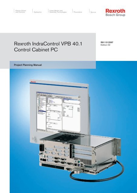
DOK-SUPPL*-VPB*40.1***-PR02-EN-P<strong>Rexroth</strong> <strong>IndraControl</strong> VPB 40.1 Control Cabinet PC<strong>Bosch</strong> <strong>Rexroth</strong> AG 5/81System Presentation1 System Presentation1.1 Brief Description VPB 40.1The VPB 40.1 is a control cabinet PC that forms a PC-based operator terminalwhen combined with a VDP 16, VDP 40 or VDP 60 display. Depending on theapplication or configuration, the operator terminal can also fulfill the controlfunctionalities.1.2 VariantsFig.1-1:1.2.1 Characteristic FeaturesVPB 40.1 with 3-slot box and connected display VDP (not included inthe scope of delivery)The VPB 40.1 is connected to the G4 or G5 serial display interface of VDP 16,VDP 40 or VDP 60 via a connecting cable with a length of up to 30 m. Thus,the VPB 40.1 can be installed in the control cabinet and the display in its dooror at the machine.The VPB 40.1 consists of two tightly connected parts:●●The PC box contains the actual PC, including the hard disk and the powersupply unit with uninterruptible power supply (UPS). Depending on thevariant the PC box provides three or four slots. The standard interface andsome special interfaces are available on a plugboard.The display interface and a RS422 interface (X39), which is to be used asalternative for the 24 V interface XCOM1, are integrated in the secondhousing part mounted on the PC box. Furthermore, five LEDs to displaydevice states and errors are arranged on this housing. Also, the optionallyavailable DVD ROM drive or the CD RW recorder system are mountedhere.The VPB 40.1 is available in two different housing variants. The possible variantsare described in the designation codes, see chapter 11.1 "Type DesignationCode" on page 73. Principally, they differ in the used PC box equippedwith 3 or 4 slots.PC box Type A Type CFree slots 3 4Voltage supplyAC 85 V to AC 264 Vor DC 24 V
6/81<strong>Bosch</strong> <strong>Rexroth</strong> AG DOK-SUPPL*-VPB*40.1***-PR02-EN-P<strong>Rexroth</strong> <strong>IndraControl</strong> VPB 40.1 Control Cabinet PCSystem PresentationPC box Type A Type CIntegrated UPSOptional drivesIntegrated UPS logic,Battery packs to be connected externallyDVD-ROM,DVD-ROM / CD-RWFig.1-2:PC box, type A and type C1.3 Operating System1.4 CommissioningFor license reasons the VPB 40.1 is only delivered with already installed operatingsystem.Mount the device properly, see also chapter 5 "Dimensions, Installation" onpage 25. Then connect the device to the power supply and, if required, to thenetwork.
DOK-SUPPL*-VPB*40.1***-PR02-EN-P<strong>Rexroth</strong> <strong>IndraControl</strong> VPB 40.1 Control Cabinet PC<strong>Bosch</strong> <strong>Rexroth</strong> AG 7/81Important Instructions on Use2 Important Instructions on Use2.1 Appropriate Use2.1.1 Introduction<strong>Rexroth</strong> products represent state-of-the-art developments and manufacturing.They are tested prior to delivery to ensure operational safety and reliability.WARNINGPhysical injury and material damage might resultfrom an inappropriate use of the products!The products are designed for the use in an industrial environment and maytherefore only be used for the intended purpose. If they are not used as intended,situations causing personal injury as well as material damage can occur.2.1.2 Areas of Use and Application<strong>Rexroth</strong> disclaims as manufacturer any warranty, liability or damagesoccurring due to inappropriate use of the products. Furthermore,<strong>Rexroth</strong> is not paying any compensation. The user isresponsible for any risks resulting from inappropriate use of theproducts.Before using <strong>Rexroth</strong> products, the following requirements must be met to ensureappropriate use of the products:●●●●Anyone handling one of the <strong>Rexroth</strong> products in any way has to read andunderstand the respective safety-related guidelines as well as the instructionson appropriate use.Hardware products have to remain in their original state, in other words,no modification regarding the design are allowed. Software products mustnot be decompiled and their source codes must not be modified.Damaged or faulty products must not be implemented or put into operation.It must be ensured that the products are installed as specified in the documentation.The VPB 40.1 by <strong>Rexroth</strong> is a control cabinet PC and becomes a PC-basedoperator terminal when used with a VDP display. Depending on the applicationand configuration, control functionality can also be carried out.NOTICEDanger of destruction of the device if not expresslystated accessories, add-on componentsand other components, cables, conduits,software and firmware is used.The VPB 40.1 may only be used with the accessories and add-on componentsspecified in this documentation. Components not named expressly mentionedmust neither be mounted nor connected. The same applies to cables and conduits.The products may only be operated with the expressly stated configurationsand component combinations as well as with the software and firmware whichis given and specified in the respective functional description.Typical areas of application of the VPB 40.1 are:
8/81<strong>Bosch</strong> <strong>Rexroth</strong> AG DOK-SUPPL*-VPB*40.1***-PR02-EN-P<strong>Rexroth</strong> <strong>IndraControl</strong> VPB 40.1 Control Cabinet PCImportant Instructions on Use●2.2 Inappropriate Use●●●●Handling systems and assembly systemsPackaging and food processing machinesPrinting machines and paper converting machinesMachine toolsWood working machinesThe VPB 40.1 may only be operated under the assembly conditions and installationconditions, in the specified position of application and under thespecified ambient conditions (temperature, degree of protection, humidity, EMCetc.) given in this documentation.The application of VPB 40.1 that are not whithin the specicified areas of applicationor under operating conditions deviating from the operating conditionsand technical data specified in the documentation are considered as "inappropriate".VPB 40.1 must not be used if ...●●it is exposed to operating conditions that do not fulfill the ambient conditionsspecified. For instance, operation under water, in case of extremevariations of temperature or in extreme maximum temperatures is not allowed.the intended applications have not expressly been allowed by <strong>Rexroth</strong>.Please note the general specifications in the general safety instructions!
DOK-SUPPL*-VPB*40.1***-PR02-EN-P<strong>Rexroth</strong> <strong>IndraControl</strong> VPB 40.1 Control Cabinet PC<strong>Bosch</strong> <strong>Rexroth</strong> AG 9/813 Safety Instructions for Electric Drives and Controls3.1 Definitions of TermsApplication DocumentationComponentControl SystemDeviceElectrical EquipmentElectric Drive SystemInstallationMachineManufacturerProduct<strong>Project</strong> <strong>Planning</strong> <strong>Manual</strong>Qualified PersonsSafety Instructions for Electric Drives and ControlsApplication documentation comprises the entire documentation used to informthe user of the product about the use and safety-relevant features for configuring,integrating, installing, mounting, commissioning, operating, maintaining,repairing and decommissioning the product. The following terms are also usedfor this kind of documentation: User Guide, Operation <strong>Manual</strong>, Commissioning<strong>Manual</strong>, Instruction <strong>Manual</strong>, <strong>Project</strong> <strong>Planning</strong> <strong>Manual</strong>, Application <strong>Manual</strong>, etc.A component is a combination of elements with a specified function, which arepart of a piece of equipment, device or system. Components of the electric driveand control system are, for example, supply units, drive controllers, mainschoke, mains filter, motors, cables, etc.A control system comprises several interconnected control components placedon the market as a single functional unit.A device is a finished product with a defined function, intended for users andplaced on the market as an individual piece of merchandise.Electrical equipment encompasses all devices used to generate, convert, transmit,distribute or apply electrical energy, such as electric motors, transformers,switching devices, cables, lines, power-consuming devices, circuit board assemblies,plug-in units, control cabinets, etc.An electric drive system comprises all components from mains supply to motorshaft; this includes, for example, electric motor(s), motor encoder(s), supplyunits and drive controllers, as well as auxiliary and additional components, suchas mains filter, mains choke and the corresponding lines and cables.An installation consists of several devices or systems interconnected for a definedpurpose and on a defined site which, however, are not intended to beplaced on the market as a single functional unit.A machine is the entirety of interconnected parts or units at least one of whichis movable. Thus, a machine consists of the appropriate machine drive elements,as well as control and power circuits, which have been assembled fora specific application. A machine is, for example, intended for processing,treatment, movement or packaging of a material. The term "machine" also coversa combination of machines which are arranged and controlled in such a waythat they function as a unified whole.The manufacturer is an individual or legal entity bearing responsibility for thedesign and manufacture of a product which is placed on the market in the individual'sor legal entity's name. The manufacturer can use finished products,finished parts or finished elements, or contract out work to subcontractors.However, the manufacturer must always have overall control and possess therequired authority to take responsibility for the product.Examples of a product: Device, component, part, system, software, firmware,among other things.A project planning manual is part of the application documentation used tosupport the sizing and planning of systems, machines or installations.In terms of this application documentation, qualified persons are those personswho are familiar with the installation, mounting, commissioning and operationof the components of the electric drive and control system, as well as with thehazards this implies, and who possess the qualifications their work requires. Tocomply with these qualifications, it is necessary, among other things,
10/81<strong>Bosch</strong> <strong>Rexroth</strong> AG DOK-SUPPL*-VPB*40.1***-PR02-EN-P<strong>Rexroth</strong> <strong>IndraControl</strong> VPB 40.1 Control Cabinet PCSafety Instructions for Electric Drives and ControlsUser1) to be trained, instructed or authorized to switch electric circuits and devicessafely on and off, to ground them and to mark them2) to be trained or instructed to maintain and use adequate safety equipment3) to attend a course of instruction in first aidA user is a person installing, commissioning or using a product which has beenplaced on the market.3.2 General Information3.2.1 Using the Safety Instructions and Passing Them on to OthersDo not attempt to install and operate the components of the electric drive andcontrol system without first reading all documentation provided with the product.Read and understand these safety instructions and all user documentation priorto working with these components. If you do not have the user documentationfor the components, contact your responsible <strong>Bosch</strong> <strong>Rexroth</strong> sales partner. Askfor these documents to be sent immediately to the person or persons responsiblefor the safe operation of the components.If the component is resold, rented and/or passed on to others in any other form,these safety instructions must be delivered with the component in the officiallanguage of the user's country.Improper use of these components, failure to follow the safety instructions inthis document or tampering with the product, including disabling of safety devices,could result in property damage, injury, electric shock or even death.3.2.2 Requirements for Safe UseRead the following instructions before initial commissioning of the componentsof the electric drive and control system in order to eliminate the risk of injuryand/or property damage. You must follow these safety instructions.●●●●●●●●●<strong>Bosch</strong> <strong>Rexroth</strong> is not liable for damages resulting from failure to observethe safety instructions.Read the operating, maintenance and safety instructions in your languagebefore commissioning. If you find that you cannot completely understandthe application documentation in the available language, please ask yoursupplier to clarify.Proper and correct transport, storage, mounting and installation, as wellas care in operation and maintenance, are prerequisites for optimal andsafe operation of the component.Only qualified persons may work with components of the electric drive andcontrol system or within its proximity.Only use accessories and spare parts approved by <strong>Bosch</strong> <strong>Rexroth</strong>.Follow the safety regulations and requirements of the country in which thecomponents of the electric drive and control system are operated.Only use the components of the electric drive and control system in themanner that is defined as appropriate. See chapter "Appropriate Use".The ambient and operating conditions given in the available applicationdocumentation must be observed.Applications for functional safety are only allowed if clearly and explicitlyspecified in the application documentation "Integrated Safety Technology".If this is not the case, they are excluded. Functional safety is a safety
DOK-SUPPL*-VPB*40.1***-PR02-EN-P<strong>Rexroth</strong> <strong>IndraControl</strong> VPB 40.1 Control Cabinet PC<strong>Bosch</strong> <strong>Rexroth</strong> AG 11/81●●●●●concept in which measures of risk reduction for personal safety dependon electrical, electronic or programmable control systems.The information given in the application documentation with regard to theuse of the delivered components contains only examples of applicationsand suggestions.The machine and installation manufacturers must– make sure that the delivered components are suited for their individualapplication and check the information given in this applicationdocumentation with regard to the use of the components,– make sure that their individual application complies with the applicablesafety regulations and standards and carry out the requiredmeasures, modifications and complements.Commissioning of the delivered components is only allowed once it is surethat the machine or installation in which the components are installedcomplies with the national regulations, safety specifications and standardsof the application.Operation is only allowed if the national EMC regulations for the applicationare met.The instructions for installation in accordance with EMC requirements canbe found in the section on EMC in the respective application documentation.The machine or installation manufacturer is responsible for compliancewith the limit values as prescribed in the national regulations.The technical data, connection and installation conditions of the componentsare specified in the respective application documentations and mustbe followed at all times.National regulations which the user must take into account●●●●European countries: In accordance with European EN standardsUnited States of America (USA):– National Electrical Code (NEC)– National Electrical Manufacturers Association (NEMA), as well aslocal engineering regulations– Regulations of the National Fire Protection Association (NFPA)Canada: Canadian Standards Association (CSA)Other countries:Safety Instructions for Electric Drives and Controls– International Organization for Standardization (ISO)– International Electrotechnical Commission (IEC)3.2.3 Hazards by Improper Use●●●●●High electrical voltage and high working current! Danger to life or seriousinjury by electric shock!High electrical voltage by incorrect connection! Danger to life or injury byelectric shock!Dangerous movements! Danger to life, serious injury or property damageby unintended motor movements!Health hazard for persons with heart pacemakers, metal implants andhearing aids in proximity to electric drive systems!Risk of burns by hot housing surfaces!
12/81<strong>Bosch</strong> <strong>Rexroth</strong> AG DOK-SUPPL*-VPB*40.1***-PR02-EN-P<strong>Rexroth</strong> <strong>IndraControl</strong> VPB 40.1 Control Cabinet PCSafety Instructions for Electric Drives and Controls●●●Risk of injury by improper handling! Injury by crushing, shearing, cutting,hitting!Risk of injury by improper handling of batteries!Risk of injury by improper handling of pressurized lines!3.3 Instructions with Regard to Specific Dangers3.3.1 Protection Against Contact with Electrical Parts and HousingsThis section concerns components of the electric drive and controlsystem with voltages of more than 50 volts.Contact with parts conducting voltages above 50 volts can cause personaldanger and electric shock. When operating components of the electric driveand control system, it is unavoidable that some parts of these componentsconduct dangerous voltage.High electrical voltage! Danger to life, risk of injury by electric shock or seriousinjury!●●●●Only qualified persons are allowed to operate, maintain and/or repair thecomponents of the electric drive and control system.Follow the general installation and safety regulations when working onpower installations.Before switching on, the equipment grounding conductor must have beenpermanently connected to all electric components in accordance with theconnection diagram.Even for brief measurements or tests, operation is only allowed if theequipment grounding conductor has been permanently connected to thepoints of the components provided for this purpose.● Before accessing electrical parts with voltage potentials higher than 50 V,you must disconnect electric components from the mains or from the powersupply unit. Secure the electric component from reconnection.●●●●●●With electric components, observe the following aspects:Always wait 30 minutes after switching off power to allow live capacitorsto discharge before accessing an electric component. Measure the electricalvoltage of live parts before beginning to work to make sure that theequipment is safe to touch.Install the covers and guards provided for this purpose before switchingon.Never touch electrical connection points of the components while poweris turned on.Do not remove or plug in connectors when the component has been powered.Under specific conditions, electric drive systems can be operated at mainsprotected by residual-current-operated circuit-breakers sensitive to universalcurrent (RCDs/RCMs).Secure built-in devices from penetrating foreign objects and water, as wellas from direct contact, by providing an external housing, for example acontrol cabinet.
DOK-SUPPL*-VPB*40.1***-PR02-EN-P<strong>Rexroth</strong> <strong>IndraControl</strong> VPB 40.1 Control Cabinet PC<strong>Bosch</strong> <strong>Rexroth</strong> AG 13/81High housing voltage and high leakage current! Danger to life, risk of injury byelectric shock!●●●Safety Instructions for Electric Drives and ControlsBefore switching on and before commissioning, ground or connect thecomponents of the electric drive and control system to the equipmentgrounding conductor at the grounding points.Connect the equipment grounding conductor of the components of theelectric drive and control system permanently to the main power supply atall times. The leakage current is greater than 3.5 mA.Establish an equipment grounding connection with a copper wire of across section of at least 10 mm 2 (8 AWG) or additionally run a secondequipment grounding conductor of the same cross section as the originalequipment grounding conductor.3.3.2 Protective Extra-Low Voltage as Protection Against Electric ShockProtective extra-low voltage is used to allow connecting devices with basic insulationto extra-low voltage circuits.On components of an electric drive and control system provided by <strong>Bosch</strong><strong>Rexroth</strong>, all connections and terminals with voltages between 5 and 50 voltsare PELV ("Protective Extra-Low Voltage") systems. It is allowed to connectdevices equipped with basic insulation (such as programming devices, PCs,notebooks, display units) to these connections.Danger to life, risk of injury by electric shock! High electrical voltage by incorrectconnection!If extra-low voltage circuits of devices containing voltages and circuits of morethan 50 volts (e.g., the mains connection) are connected to <strong>Bosch</strong> <strong>Rexroth</strong>products, the connected extra-low voltage circuits must comply with the requirementsfor PELV ("Protective Extra-Low Voltage").3.3.3 Protection Against Dangerous MovementsDangerous movements can be caused by faulty control of connected motors.Some common examples are:●●●●●●Improper or wrong wiring or cable connectionOperator errorsWrong input of parameters before commissioningMalfunction of sensors and encodersDefective componentsSoftware or firmware errorsThese errors can occur immediately after equipment is switched on or evenafter an unspecified time of trouble-free operation.The monitoring functions in the components of the electric drive and controlsystem will normally be sufficient to avoid malfunction in the connected drives.Regarding personal safety, especially the danger of injury and/or property damage,this alone cannot be relied upon to ensure complete safety. Until theintegrated monitoring functions become effective, it must be assumed in anycase that faulty drive movements will occur. The extent of faulty drive movementsdepends upon the type of control and the state of operation.
14/81<strong>Bosch</strong> <strong>Rexroth</strong> AG DOK-SUPPL*-VPB*40.1***-PR02-EN-P<strong>Rexroth</strong> <strong>IndraControl</strong> VPB 40.1 Control Cabinet PCSafety Instructions for Electric Drives and ControlsDangerous movements! Danger to life, risk of injury, serious injury or propertydamage!A risk assessment must be prepared for the installation or machine, with itsspecific conditions, in which the components of the electric drive and controlsystem are installed.As a result of the risk assessment, the user must provide for monitoring functionsand higher-level measures on the installation side for personal safety. Thesafety regulations applicable to the installation or machine must be taken intoconsideration. Unintended machine movements or other malfunctions are possibleif safety devices are disabled, bypassed or not activated.To avoid accidents, injury and/or property damage:●●●●●●●●●Keep free and clear of the machine’s range of motion and moving machineparts. Prevent personnel from accidentally entering the machine’s rangeof motion by using, for example:– Safety fences– Safety guards– Protective coverings– Light barriersMake sure the safety fences and protective coverings are strong enoughto resist maximum possible kinetic energy.Mount emergency stopping switches in the immediate reach of the operator.Before commissioning, verify that the emergency stopping equipmentworks. Do not operate the machine if the emergency stopping switchis not working.Prevent unintended start-up. Isolate the drive power connection by meansof OFF switches/OFF buttons or use a safe starting lockout.Make sure that the drives are brought to safe standstill before accessingor entering the danger zone.Additionally secure vertical axes against falling or dropping after switchingoff the motor power by, for example,– mechanically securing the vertical axes,– adding an external braking/arrester/clamping mechanism or– ensuring sufficient counterbalancing of the vertical axes.The standard equipment motor holding brake or an external holding brakecontrolled by the drive controller is not sufficient to guarantee personalsafety!Disconnect electrical power to the components of the electric drive andcontrol system using the master switch and secure them from reconnection("lock out") for:– Maintenance and repair work– Cleaning of equipment– Long periods of discontinued equipment usePrevent the operation of high-frequency, remote control and radio equipmentnear components of the electric drive and control system and theirsupply leads. If the use of these devices cannot be avoided, check themachine or installation, at initial commissioning of the electric drive andcontrol system, for possible malfunctions when operating such high-frequency,remote control and radio equipment in its possible positions ofnormal use. It might possibly be necessary to perform a special electromagneticcompatibility (EMC) test.
DOK-SUPPL*-VPB*40.1***-PR02-EN-P<strong>Rexroth</strong> <strong>IndraControl</strong> VPB 40.1 Control Cabinet PC<strong>Bosch</strong> <strong>Rexroth</strong> AG 15/81Safety Instructions for Electric Drives and Controls3.3.4 Protection Against Magnetic and Electromagnetic Fields During Operationand MountingMagnetic and electromagnetic fields generated by current-carrying conductorsor permanent magnets of electric motors represent a serious danger to personswith heart pacemakers, metal implants and hearing aids.Health hazard for persons with heart pacemakers, metal implants and hearingaids in proximity to electric components!●●●3.3.5 Protection Against Contact With Hot PartsPersons with heart pacemakers and metal implants are not allowed toenter the following areas:– Areas in which components of the electric drive and control systemsare mounted, commissioned and operated.– Areas in which parts of motors with permanent magnets are stored,repaired or mounted.If it is necessary for somebody with a heart pacemaker to enter such anarea, a doctor must be consulted prior to doing so. The noise immunity ofimplanted heart pacemakers differs so greatly that no general rules canbe given.Those with metal implants or metal pieces, as well as with hearing aids,must consult a doctor before they enter the areas described above.Hot surfaces of components of the electric drive and control system. Risk ofburns!●●●●●●Do not touch hot surfaces of, for example, braking resistors, heat sinks,supply units and drive controllers, motors, windings and laminated cores!According to the operating conditions, temperatures of the surfaces canbe higher than 60 °C (140 °F) during or after operation.Before touching motors after having switched them off, let them cool downfor a sufficient period of time. Cooling down can require up to 140 minutes!The time required for cooling down is approximately five times thethermal time constant specified in the technical data.After switching chokes, supply units and drive controllers off, wait 15 minutesto allow them to cool down before touching them.Wear safety gloves or do not work at hot surfaces.3.3.6 Protection During Handling and MountingFor certain applications, and in accordance with the respective safety regulations,the manufacturer of the machine or installation must take measuresto avoid injuries caused by burns in the final application. Thesemeasures can be, for example: Warnings at the machine or installation,guards (shieldings or barriers) or safety instructions in the applicationdocumentation.Risk of injury by improper handling! Injury by crushing, shearing, cutting, hitting!●●●Observe the relevant statutory regulations of accident prevention.Use suitable equipment for mounting and transport.Avoid jamming and crushing by appropriate measures.
16/81<strong>Bosch</strong> <strong>Rexroth</strong> AG DOK-SUPPL*-VPB*40.1***-PR02-EN-P<strong>Rexroth</strong> <strong>IndraControl</strong> VPB 40.1 Control Cabinet PCSafety Instructions for Electric Drives and Controls●●●●●Always use suitable tools. Use special tools if specified.Use lifting equipment and tools in the correct manner.Use suitable protective equipment (hard hat, safety goggles, safety shoes,safety gloves, for example).Do not stand under hanging loads.Immediately clean up any spilled liquids from the floor due to the risk ofslipping.3.3.7 Battery SafetyBatteries consist of active chemicals in a solid housing. Therefore, improperhandling can cause injury or property damage.Risk of injury by improper handling!●●●●●●Do not attempt to reactivate low batteries by heating or other methods (riskof explosion and cauterization).Do not attempt to recharge the batteries as this may cause leakage orexplosion.Do not throw batteries into open flames.Do not dismantle batteries.When replacing the battery/batteries, do not damage the electrical partsinstalled in the devices.Only use the battery types specified for the product.Environmental protection and disposal! The batteries contained inthe product are considered dangerous goods during land, air, andsea transport (risk of explosion) in the sense of the legal regulations.Dispose of used batteries separately from other waste. Observe thenational regulations of your country.3.3.8 Protection Against Pressurized SystemsAccording to the information given in the <strong>Project</strong> <strong>Planning</strong> <strong>Manual</strong>s, motors andcomponents cooled with liquids and compressed air can be partially suppliedwith externally fed, pressurized media, such as compressed air, hydraulics oil,cooling liquids and cooling lubricants. Improper handling of the connected supplysystems, supply lines or connections can cause injuries or property damage.Risk of injury by improper handling of pressurized lines!●●●●●Do not attempt to disconnect, open or cut pressurized lines (risk of explosion).Observe the respective manufacturer's operating instructions.Before dismounting lines, relieve pressure and empty medium.Use suitable protective equipment (safety goggles, safety shoes, safetygloves, for example).Immediately clean up any spilled liquids from the floor due to the risk ofslipping.
DOK-SUPPL*-VPB*40.1***-PR02-EN-P<strong>Rexroth</strong> <strong>IndraControl</strong> VPB 40.1 Control Cabinet PC<strong>Bosch</strong> <strong>Rexroth</strong> AG 17/81Safety Instructions for Electric Drives and ControlsEnvironmental protection and disposal! The agents (e.g., fluids)used to operate the product might not be environmentally friendly.Dispose of agents harmful to the environment separately from otherwaste. Observe the national regulations of your country.3.4 Explanation of Signal Words and the Safety Alert SymbolThe Safety Instructions in the available application documentation contain specificsignal words (DANGER, WARNING, CAUTION or NOTICE) and, whererequired, a safety alert symbol (in accordance with ANSI Z535.6-2006).The signal word is meant to draw the reader's attention to the safety instructionand identifies the hazard severity.The safety alert symbol (a triangle with an exclamation point), which precedesthe signal words DANGER, WARNING and CAUTION, is used to alert thereader to personal injury hazards.DANGERIn case of non-compliance with this safety instruction, death or serious injurywill occur.WARNINGIn case of non-compliance with this safety instruction, death or serious injurycould occur.CAUTIONIn case of non-compliance with this safety instruction, minor or moderate injurycould occur.NOTICEIn case of non-compliance with this safety instruction, property damage couldoccur.
18/81<strong>Bosch</strong> <strong>Rexroth</strong> AG DOK-SUPPL*-VPB*40.1***-PR02-EN-P<strong>Rexroth</strong> <strong>IndraControl</strong> VPB 40.1 Control Cabinet PC
DOK-SUPPL*-VPB*40.1***-PR02-EN-P<strong>Rexroth</strong> <strong>IndraControl</strong> VPB 40.1 Control Cabinet PC<strong>Bosch</strong> <strong>Rexroth</strong> AG 19/81Technical Data4 Technical Data4.1 PC BoxPC box Type C Type AProcessorRAMHard diskOptional drivesInterfacesCeleron-M, 1.3 GHzPentium-M 1.8 GHzand integrated graphics controllerwith a maximum of 8 MB video memory512 MB1 GBMin. 30 GB, mounted within a vibration-resistant suspensionDVD ROM or DVD ROM / CD RW●●●1 × display interface (25-pin, D-Sub)1 × parallel interface (25-pin, D-Sub)1 x external VGA connection (15-pin, HD-Sub)● 2 × USB connection (type A)●●●●1 × Ethernet connection (RJ 45, 10/100 base-T)1 × keyboard connection (PS/2)1 × mouse connection (PS/2)1 x external battery connection● 3 x serial standard interfaces RS232 (9-pin, D-Sub) 1)●1 × RS422 interface (9-pin, D-Sub)Slots 3 × PCI, 1 × PCI / ISA 2 × PCI, 1 × PCI / ISADegree of protectionVoltage supplyMax. powerconsumptionWeightPC box: IP 20AC 85 V to AC 264 V or DC 24 V200 Wwithout CD-ROM 6.1 kgwith CD-ROM + 0.2 kg additionallyfor 4 th slot + 0.1 kg additionallyFig.4-1:Technical data of the PC box4.2 Power Supply Unit 115 V / 230 VNominal input voltageInput voltage rangeInput currentAC 115 V or AC 230 VAC 85 V... AC 264 V1.0 A for nominal voltage AC 230 V2.0 A for nominal voltage AC 115 V1)For connected display: two serial interfaces
20/81<strong>Bosch</strong> <strong>Rexroth</strong> AG DOK-SUPPL*-VPB*40.1***-PR02-EN-P<strong>Rexroth</strong> <strong>IndraControl</strong> VPB 40.1 Control Cabinet PCTechnical DataMax. inrush current(cold start 25 °C)40 A for nominal voltage AC 230 V20 A for nominal voltage AC 115 VOutput voltages+5 V+12 V-12 V+20 VISO 6 VMaximum output powerCurrent (max.)20 A3 A500 mA2 A200 mA160 WTolerance (incl. residual ripple)±5 %±5 %±5 %±5 %±5 %Efficiency 0.8Fig.4-2:Technical data of the power supply unit 115 V / 230 V4.3 24 V Voltage SupplyNOTICEThe control cabinet PC VPB 40.1 can be damagedif the power supply unit is switched off ifthe total output power exceeds 160 W.When maximum output currents are specified, please observe that the currentsare the maximum possible currents for the respective output voltage. However,it is not possible to produce the maximum current from all output voltages, asthe maximum total output power of 160 W must not be exceeded.Nominal input voltageDC 24 VInput voltage range DC 24 V +20 %, -15 %Emitted interference and surgeimmunityMax. input currentMax. inrush currentU max = 35 V (for t < 100 ms)6 A for nominal voltage 24 V25 A for nominal voltage 24 VOutput voltages+5 V+12 V+24 V-12 VISO 6 VMax. output powerCurrent (max.)13 A3 A2 A500 mA200 mA110 WTolerance (incl. residual ripple)±5 %±5 %±5 %±5 %±5 %Efficiency 0.8Fig.4-3:Technical data of the 24 V power supply unit
DOK-SUPPL*-VPB*40.1***-PR02-EN-P<strong>Rexroth</strong> <strong>IndraControl</strong> VPB 40.1 Control Cabinet PC<strong>Bosch</strong> <strong>Rexroth</strong> AG 21/81Technical Data4.4 Ambient ConditionsNOTICEThe control cabinet PC VPB 40.1 can be damagedif the power supply unit is switched off ifthe total output power exceeds 110 W.When maximum output currents are specified, please observe that the currentsare the maximum possible currents for the respective output voltage. However,it is not possible to produce the maximum current from all output voltages atthe same time, as the maximum total output power (= max. 110 W) must notbe exceeded.In operationStorage / TransportMax. surrounding air temperature +5 ℃ ... +45 °C -20 ℃ to +60 ℃Max. temperature gradient Temporal temperature changes up to 3 ℃per minuteNot definedRelative humidityAir pressureMechanical strengthClimatic class 3K3 according to EN60721,non-condensing.Up to 2000 m above MSL according toDIN 60204Max. vibration:Frequency range:10 to 150 HzExcursion: 0.075 mm for 10 ... 57 HzAcceleration: 1 g for 57 to 150 Hzacc. to EN 60068-2-6Climatic class 3K3 according to EN60721,non-condensing.Max. shock:15 g acc. to DIN IEC 68-2-27,No breakdown of the functionDegree of pollution 2 2Fig.4-4:Ambient conditions4.5 Used StandardsThe system components of the VPB 40.1 correspond to the following standards:StandardEN 60 204-1EN 50 081-2EN 50 082-2EN 60 742EN 60 950EN 61 131EN 61 131-2EN 418MeaningElectrical equipment of machinesGeneric standards - emission standard (industrial environments)Generic standards - noise immunity (industrial environments)Transformer for 24 V power supply unit, protective separationOvervoltage category II24 V outputs requirements24 V current supply requirementsSafety of machinery, emergency stop devices
22/81<strong>Bosch</strong> <strong>Rexroth</strong> AG DOK-SUPPL*-VPB*40.1***-PR02-EN-P<strong>Rexroth</strong> <strong>IndraControl</strong> VPB 40.1 Control Cabinet PCTechnical DataStandardEN 60 529EN 60 068-2-6EN 60 068-2-27MeaningDegrees of protection (including housings and installationcompartments)Vibration testShock testFig.4-5:Used standards4.6 CE Marking4.6.1 Declaration of ConformityThe electronic products described in the project planning manual comply withthe requirements and goals of the following EC guideline and with the agreedEuropean standards:EMC guideline 2004/108/ECThe electronic products described in the project planning manual comply withthe requirements on the operation within the industrial environment:Standard Title EditionDIN EN61000-6-4(VDE 0839-6-4)DIN EN61000-6-2(VDE 0839-6-2)Electromagnetic compatibility (EMC)Volume: 6-4: Generic standards - emitted interferencefor industrial environments (IEC61000-6-4:2006)Electromagnetic compatibility (EMC)Volume: 6-2: Generic standards – noise immunityfor industrial environments (IEC 61000-6-2:2005)September2007March 2006Fig.4-6:4.6.2 Note for the Machine ManufacturerElectromagnetic compatibility (EMC) standardsThe electronic products described in this project planning manual do not fallunder the machines listed in the EC guidelines. Therefore, explanations are notrequired for the 89/392/EMC guideline and do not exist.89/392/EMC, the EC guideline for machines, specifies the requirements on amachine. In this guideline, a machine is defined as a combination of the componentsor mechanisms combined with each other. The described productsbelong to the electrical equipment of a machine. Therefore, they are to be includedin the declaration of conformity of the machine manufacturer.The standard EN 60204-1 (safety of machinery, general requirements on theelectrical equipment of the machines) can be used for the electrical equipmentof the machines.NOTICELoss of CE conformity due to modifications ofthe device.The CE marking is only valid for the device in its delivery status. After modifyingthe device, the CE conformity is to be verified.
DOK-SUPPL*-VPB*40.1***-PR02-EN-P<strong>Rexroth</strong> <strong>IndraControl</strong> VPB 40.1 Control Cabinet PC<strong>Bosch</strong> <strong>Rexroth</strong> AG 25/81Dimensions, Installation5 Dimensions, Installation5.1 General Information5.2 Housing DimensionsAll values are given in mm.The VPB 40.1 can be mounted, e. g. in the control cabinet with the help of fourfastening holes. For the corresponding dimensions, please refer to figures fig.5-1 "Horizontal mounting of the VPB 40.1 (device with 3-slot box)" on page25 and fig. 5-5 "VPB 40.1 dimensions (top view)" on page 27.The VPB 40.1 can be mounted horizontally (net connection on the left side) aswell as vertically (net connection on the top).364350 7X20A3A230A1X19XCOM31XDPXMouseXUSB1130,2185F1X10XCOM1S1XCOM2 XVGA XEthernet XKeyb.XUSB2XLPT11 1X39 X71VI Vo T UPSHDFig.5-1:Horizontal mounting of the VPB 40.1 (device with 3-slot box)The height of the VPB 40.1 depends on the number of slots of the used PC box:PC box Number of slots VPB 40.1 heightType A 3 130.2 mm (plus 10 mm for the screw of the harddisk cover)Type C 4 150.5 mm (plus 10 mm for the screw of the harddisk cover)Fig.5-2:VPB 40.1 height
1126/81<strong>Bosch</strong> <strong>Rexroth</strong> AG DOK-SUPPL*-VPB*40.1***-PR02-EN-P<strong>Rexroth</strong> <strong>IndraControl</strong> VPB 40.1 Control Cabinet PCDimensions, InstallationX20F1X19X10XCOM3XCOM1 S1364350 7A3A2A1XDPXMouseXUSB1XCOM2 XVGA XEthernet XKeyb.XUSB2 XLPT11 1X39 X71VI Vo T UPSHD85130,230Fig.5-3:Vertical mounting of the VPB 40.1 (device with 3-slot box)The width of the VPB 40.1 depends on the number of slots of the used PC box:PC box Number of slots VPB 40.1 widthType A 3 130.2 mm (plus 10 mm for the screw of the harddisk cover)Type C 4 150.5 mm (plus 10 mm for the screw of the harddisk cover)Fig.5-4:VPB 40.1 width
DOK-SUPPL*-VPB*40.1***-PR02-EN-P<strong>Rexroth</strong> <strong>IndraControl</strong> VPB 40.1 Control Cabinet PC<strong>Bosch</strong> <strong>Rexroth</strong> AG 27/81Dimensions, Installation214262,5Fig.5-5:VPB 40.1 dimensions (top view)5.3 Installation NotesMinimum distances for cooling, cables,DVD drive and maintenance●●●●●Avoid installation locations exposed to direct sunlight/UV-light becausethis causes additional heat development.Install the control cabinet PC in a way ensuring easy access to the connectorpanel.Provide a sufficient space of 50 mm (on all sides of the device) for sufficientcooling and cable routing.Lay all connecting cables in loops and use strain reliefs for all cables.Keep as much distance as possible to noise sources.For cooling, cables, maintenance and the DVD drive the following minimumdistances must be observed as shown in the following figures:25Provide sufficient distance forhard disk replacement, if necessary10X20A3A2A1X19XCOM3XDPXMouse1XUSB111min. 50F1X10XCOM1S1XCOM2XVGAXEthernetXKeyb.XUSB2XLPT11 1 VI Vo T UPS HDX39X71Fig.5-6:Minimum distances for cooling, cables, DVD drive and maintenance:Front View
28/81<strong>Bosch</strong> <strong>Rexroth</strong> AG DOK-SUPPL*-VPB*40.1***-PR02-EN-P<strong>Rexroth</strong> <strong>IndraControl</strong> VPB 40.1 Control Cabinet PCDimensions, Installation50min. 50214300 (depends on the connector and bending radius of the cable)Provide sufficient distance to openthe DVD drive, if necessary(DVD tray opens 130 mm).VDP connecting cableFig.5-7:Minimum distances for cooling, cables, DVD drive and maintenance:Top view
DOK-SUPPL*-VPB*40.1***-PR02-EN-P<strong>Rexroth</strong> <strong>IndraControl</strong> VPB 40.1 Control Cabinet PC<strong>Bosch</strong> <strong>Rexroth</strong> AG 29/816 Display and Operating Components6.1 Monitor and KeyboardDisplays with foil keyboard andtouch screenDisplay and Operating ComponentsTo display and operate the VPB 40.1 we recommend the displays VDP 16,VDP 40 and VDP 60 especially designed by <strong>Bosch</strong> <strong>Rexroth</strong> for industrial applications.The displays are connected with the VPB 40.1 via the G5 displayinterface. These displays are equipped either with a keypad or with a touchscreen with varying display size.Connection monitorFor detailed information, please refer to the relevant documentation.A standard monitor (female connector XVGA), a PS2 keyboard (female connectorXKeyb.) and a PS2 mouse (female connector XMouse) can be alsoconnected with the VPB 40.1. Please observe that most of the standard miceand keyboards are not suitable for the industrial environment and are very susceptibleto electromagnetic disturbances.NOTICE6.2 Operating and Error DisplayLEDs for operating and error displayThe VPB 40.1 control cabinet PC cannot beoperated if keyboard and mouse are connectedto the VPB 40.1 if a VDP display is used.If a VDP is used, keyboard and mouse may only be connected to this display.Don't use the keyboard and mouse interfaces at the VPB 40.1.In the lower right part of the connector panel there are five LEDs to display thedevice states and errors. Apply the specified measure if one of the followingLEDs display either an error or a note.LED Display Meaning MeasureVi LED green Normal mode -LED offNo supply voltage AC 230 V/115 Vor DC 24 VCheck the supply voltageat the power supply unit!Vo LED green Normal mode -LED off Internal 5 V supply faulty! -T LED off Normal modeLED flashesyellowOvertemperatureReduce surrounding airtemperature!Check fan on the controlcabinet PC!
30/81<strong>Bosch</strong> <strong>Rexroth</strong> AG DOK-SUPPL*-VPB*40.1***-PR02-EN-P<strong>Rexroth</strong> <strong>IndraControl</strong> VPB 40.1 Control Cabinet PCDisplay and Operating ComponentsLED Display Meaning MeasureUPS LED off Normal mode -LED redVPB 40.1 is currently operating inbattery mode, i. e. no voltage supplyis available!Restore power supply andinitiate controlled restart!LED flashesredBattery pack discharged, defectiveor not connectedCheck battery!Maintain the charging timeof 5 hours!HDD LED yellow Hard disk access -Fig.6-1:LEDs to operating and error display on the connector panel
DOK-SUPPL*-VPB*40.1***-PR02-EN-P<strong>Rexroth</strong> <strong>IndraControl</strong> VPB 40.1 Control Cabinet PC<strong>Bosch</strong> <strong>Rexroth</strong> AG 31/81Connections7 Connections7.1 View on the Connector PanelX20A3A2A1X19XCOM3XDPXMouse1XUSB111F1X10XCOM1S1XCOM2XVGAXEthernetXKeyb.XUSB2XLPT11 1 VI Vo T UPS HDX39X71Fig.7-1:Position of the connections7.2 Interfaces7.2.1 General InformationNot each variant provides all the described interfaces. Which interfacesare integrated in the respective device depends on the deviceconfiguration.NOTICEMalfunctions due to insufficient shielding!Use only shielded cables and metallic, conductive connectors or coupling housingswith large-area shield support.7.2.2 OverviewInterfaces - OverviewDesignationat thehousingConnection typeConnector type (integrated)Mating connector orcable (from outside)XCOM1,XCOM2,XCOM3Serial interfaces:RS232 (UART 16550)D-Sub male connector,9-pinD-Sub female connector,9-pinXLPT1Parallel interface: supportsstandard SPP-, EPP-, ECPmodeD-Sub female connector,25-pinD-Sub male connector,25-pin (e. g.printer cable)XUSB1,XUSB2USB interfacesUSB female connector,4-pin, type AUSB male connector,4-pinXEthernet Network connection:Ethernet 10Base T /100Base XRJ45 female connector,8-pinRJ45 connector(twisted pair, 8-wire)XVGAVGA connection of an externalmonitorVGA-HDconnector,femaleVGA-HD male connector,15-pin15-pin
32/81<strong>Bosch</strong> <strong>Rexroth</strong> AG DOK-SUPPL*-VPB*40.1***-PR02-EN-P<strong>Rexroth</strong> <strong>IndraControl</strong> VPB 40.1 Control Cabinet PCConnectionsDesignationat thehousingConnection typeConnector type (integrated)Mating connector orcable (from outside)XKeyb. PS/2 keyboard/mouse Mini-DIN PS/2 femaleconnector, 6-pinXMouse PS/2 mouse Mini-DIN PS/2 femaleconnector, 6-pinMini-DIN PS/2 maleconnector, 6-pinMini-DIN PS/2 maleconnector, 6-pinX10PC voltage supply: DC 24 V(alternative to X20)Male connector terminal,MSTB 1.5, 4-pinFemale connectorterminal, MSTB 1.5,4-pinX19Battery for uninterruptiblepower supply (UPS)Tyco/AMPN-LOK,2-pinMATE-Cable to the batteryof the UPSX20 PC voltage supply: AC 230V/115 VX39 or X43 Serial RS422 interfaceDisplay interfacesAC male connectorD-Sub connector,9-pinAC female connectorD-Sub female connector,9-pinX71orG4 display interface (forVDP 16, VDP 40 or VDP 60)D-Sub female connector,25-pinD-Sub male connector,25-pinX71G5 display interface (forVDP 16 or VDP 40)D-Sub female connector,25-pinD-Sub male connector,25-pinFig.7-2:VPB 40.1 interfaces7.2.3 Serial Interfaces XCOM1 to XCOM3XCOM1 to XCOM3 –Serial InterfacesDepending on the device variant up to three serial standard interfaces areavailable at the connections XCOM1 to XCOM3.D-Sub connector, 9-pinTypeCable lengthRS23215 m max.Cable type Shielded, cross-section min. 0.14 mm 2Transmission rateHandshakeMax. 115200 bits/sHardware and software handshake (XON, XOFF)XCOM1 XCOM2 XCOM3Interrupt (IRQ) 4 3 11I/O address 3F8H 2F8H 3E8HBIOS presetting Enabled Enabled EnabledFig.7-3:Serial interfaces - XCOM1 to XCOM3
DOK-SUPPL*-VPB*40.1***-PR02-EN-P<strong>Rexroth</strong> <strong>IndraControl</strong> VPB 40.1 Control Cabinet PC<strong>Bosch</strong> <strong>Rexroth</strong> AG 33/81ConnectionsFig.7-4:Pin assignment XCOM1 to XCOM3NOTICE7.2.4 Serial Interfaces, SettingsControl panelBIOSA safe function of a device connected to aCOM interface is not possible if the COM interfaceis already used internally.A safe function of a device connected to a COM interface is only possible if theCOM interface is not used internally. Depending on the variant and the usedsoftware packages, the interfaces can already be occuppied.To find out settings of the transfer parameters for the serial interfaces pleaserefer to the description of the installed operating system. In Windows XP underStart Settings Control panel Device manager.The BIOS settings of the serial interfaces are:InterfaceCOM1COM2COM3COM4BIOS setting3F8H2F8H3E8H2E8HFig.7-5:BIOS settingsNOTICEA safe function of a device connected to aCOM interface is not possible if Interrupt or I/Oaddress conflicts arise.Interrupt (IRQ) and I/O address have to correspond to the settings carried outin BIOS.If an address conflict regarding COM3 occurs, e. g., IRQ 11 is already occupiedby other extension cards of the PC, free IRQs have to be used.RS232 interface for <strong>IndraControl</strong>VPB 40.1A new motherboard is used for the the <strong>IndraControl</strong> devices VPB and VPP type1 devices. Due to the new motherboard, serial RS232 components may notfunction correctly. The reason for this is a change of Interrupt 10 and 11 of theserial COM interfaces in the serial COM ports 3 and 4. For troubleshooting
34/81<strong>Bosch</strong> <strong>Rexroth</strong> AG DOK-SUPPL*-VPB*40.1***-PR02-EN-P<strong>Rexroth</strong> <strong>IndraControl</strong> VPB 40.1 Control Cabinet PCConnectionsadjust the values of the COM interfaces in the BIOS. Alternatively, the IRQ canalso be adjusted via the configuration software of the serial device.BIOS setting since Q1/2007 BIOS setting until Q1/2007Menu: I/O Device ConfigurationMenu: Integrated PeripheralsSerial port C (COM3):[Enabled]Onboard Serial Port3:[3E8/IRQ11]Base I/O address:[3E8]Interrupt: [IRQ 10]Serial port D (COM4):[Enabled]Onboard Serial Port4:[2E8/IRQ10]Base I/O address:[2E8]Interrupt: [IRQ 11]Fig.7-6:7.2.5 Parallel Interface XLPT1XLPT1 – Parallel interface for printer,scanner, etc.BIOS settings of the COM interfacesFor any questions, please contact your service/sales person or the help desk+49 (0) 9352 / 40 50 60, see also chapter 12 "Service and Support" on page77.D-Sub female connector, 25-pinType:SPP (ex works), EPP, ECPCable length:3 m max.Cable type: Shielded, cross-section min. 0.14 mm 2Interrupt (IRQ): 7I/O address:378HFig.7-7:Parallel interface - XLPT1
DOK-SUPPL*-VPB*40.1***-PR02-EN-P<strong>Rexroth</strong> <strong>IndraControl</strong> VPB 40.1 Control Cabinet PC<strong>Bosch</strong> <strong>Rexroth</strong> AG 35/81Connections3XLPT1Interface modeEPP SPPmax. 3mm113 114 2514 25WriteData0Data1STROBEData0Data1123Data2 Data24Data3 Data35Data4 Data46Data5 Data57Data6 Data68Data7 Data791Intr ACK10Wait BUSY11n.u. PAPER out12n.u. SEL out13Datastb AUTOFD14n.u. ERROR15n.u. INIT16Addrstrb SEL in17GND GND18GND GND19GND GND20GND GND21GND GND22GND GND23GND GND24GND GND25To peripheraldevicesShield overmetallic housing ofthe plug-in connectorFig.7-8:7.2.6 USB Interfaces XUSBXUSB – serial interfaces for printer,scanner, CD-ROM driveXLPT1 interfaceThe parallel interface normally runs in the standard mode SPP. The parallelinterface can be operated also in the EPP-Mode (Enhanced Parallel Port) or inthe ECP-Mode (Extended Capabilities Port) if adequate peripheral componentsare available. The mode can be changed in the BIOS settings.The devices feature two USB interfaces on the connector panel (XUSB1 andXUSB2) and one in the device (on the carrier board).NOTICEA connected USB device does not function ifthe current consumption exceeds 500 mA.The maximum power consumption of the connected device must not exceed500 mA per USB connector. If the load exceeds 500 mA, the internal currentmonitoring is activated.
36/81<strong>Bosch</strong> <strong>Rexroth</strong> AG DOK-SUPPL*-VPB*40.1***-PR02-EN-P<strong>Rexroth</strong> <strong>IndraControl</strong> VPB 40.1 Control Cabinet PCConnectionsFig.7-9:PinUSB interfaces XUSB1 and XUSB2Function1 USB power supply (max. 500 mA)2 Data -3 Data +4 USB groundFig.7-10:7.2.7 Ethernet Interface XEthernetXEthernet – Network ConnectionUSB interfaces - XUSB1 and XUSB2The VPB 40.1 can be connected to an Ethernet network via the XEthernet interface.RJ45, female connector, 8-pinType:Cable length:Cable type:Transmission rate:Ethernet 10Base T / 100Base X100 m max.Shielded, twisted pair10 or 100 MBit/sFig.7-11:Ethernet interface - XEthernetFig.7-12:Ethernet interface XEthernetThe driver configuration of the network connection can be called up in the taskbar or in the "Control Panel" with the "Network board" icon. Here you can setamong other values, if the data transmission shall occur with 10 Mbit/s or with100 Mbits/s via the network.
DOK-SUPPL*-VPB*40.1***-PR02-EN-P<strong>Rexroth</strong> <strong>IndraControl</strong> VPB 40.1 Control Cabinet PC<strong>Bosch</strong> <strong>Rexroth</strong> AG 37/81Connections7.2.8 VGA Interface XVGAXVGA – Connection external monitorNOTICENo or incorrect network data transmission if thedata rate is set manually!Please note that the network card of the outstation has to be able to processthe same data transmission rate.An external monitor can be connected to the VGA connection (XVGA).●Video RAM: max. 8 MBNOTICENo display of BIOS messages on the externalmonitor if the monitor has been connected firstafter switching on the VPB 40.1.Please observe that the external monitor has to be already connected duringthe booting process of the VPB 40.1, as otherwise the VGA interface is notinitialized by the BIOS.NOTICENo screen output via an additional graphicscard if the internal graphics adapter is notswitched off.Before plugging-in a graphics card, the video adapter integrated in BIOS is tobe switched off.HD female connector, 15-pinCable length:1.5 m max.Cable type: Shielded, cross-section min. 0.14 mm 2Max. resolution:1600 x 1200 pixels, 4294 mill. colors max.Fig.7-13:VGA inerface - XVGAFig.7-14:XVGA interface
38/81<strong>Bosch</strong> <strong>Rexroth</strong> AG DOK-SUPPL*-VPB*40.1***-PR02-EN-P<strong>Rexroth</strong> <strong>IndraControl</strong> VPB 40.1 Control Cabinet PCConnectionsResolutionThe following standard resolutions can be operated with an image refresh rateof at least 72 Hz.●●●●VGA mode: 640 × 480 pixels 32 bit colorsSVGA mode: 800 × 600 pixels 32 bit colorsXGA mode: 1024 × 768 pixels 32 bit colorsSXGA mode: 1280 x 1024 pixels, 24 bit colorsThe resolution and number of the colors are set in the control panel of the operatingsystem.WARNINGSetting incorrect resolutions and colors maydestroy the monitor!Please note the technical data of the monitor and adapt the operating systemparameters accordingly.Recommended monitors for external use are low-radiation models accordingto TCO95. Additionally, you should achieve the desired display resolution witha refresh rate of at least 72 Hz.7.2.9 Combined Keyboard/Mouse Interface XKeyb.XKeyb. – PS/2 Mini DIN Keyboard /Mouse InterfacePS/2 Mini DIN female connector, 6-pinCable length:1.5 m max.Cable type: Shielded, cross-section min. 0.14 mm 2Fig.7-15:Combined keyboard/mouse interface - PS/2 Mini-DIN-connectorXPS2KB6 54 32 1ShieldKeyboard DataMouse DataGNDPower, DC +5VKeyboard ClockMouse Clock123456max 1.5 mKeyboardShield above metallichousing of the plugFig.7-16:Combined keyboard/mouse interface XKeyb.7.2.10 Mouse Interface XMouseXMouse – PS/2 mouse interfaceNOTICENo mouse or keyboard entries are possible if amouse or keyboard is plugged in the <strong>VPB40.1</strong> if a VDP is connected.If a BTT or VDP is connectd, keyboard and mouse may be connected only tothis device and not to the VPB 40.1.PS/2 Mini DIN female connector, 6-pinCable length:1.5 m max.Cable type: Shielded, cross-section min. 0.14 mm 2
DOK-SUPPL*-VPB*40.1***-PR02-EN-P<strong>Rexroth</strong> <strong>IndraControl</strong> VPB 40.1 Control Cabinet PC<strong>Bosch</strong> <strong>Rexroth</strong> AG 39/81ConnectionsPS/2 Mini DIN female connector, 6-pinInterrupt (IRQ): 12BIOS presetting: PS/2 mouse support: EnabledPS/2Mouse: Auto detectFig.7-17:Mouse interface - PS/2 mousemax. 1.5 mXPS2MSMouse DataGNDPower, +5VDCMouse Clock123456MouseShieldFig.7-18:Mouse interface XMouseShield above the metallic housingof the plugIf a PS/2 mouse is not recognized by the system, the mouse must be activatedin the BIOS by switching from "Disabled" to "Autodetect". The operating systemwill not recognize the plugging-in of an external mouse after completed startup,because the mouse is initialized during the booting process.NOTICEEntries with a connected mouse are only possibleif it is PS/2 compatible.The connected mouse must comply with the PS/2 standard. Normally, the BIOSreserves IRQ 12 for the PS/2 mouse If there are address conflicts, e. g., if IRQ12 has already been used by another PC extension card, the IRQ of this extensioncard should be changed to unassigned IRQ.NOTICEEntries with a connected mouse are only possibleif no other mouse is connected in parallel.If a keyboard with an integrated mouse is connected to the XKeby interface, noadditional mouse must be connected to the mouse interface. The mouse integratedin the keyboard is available.
40/81<strong>Bosch</strong> <strong>Rexroth</strong> AG DOK-SUPPL*-VPB*40.1***-PR02-EN-P<strong>Rexroth</strong> <strong>IndraControl</strong> VPB 40.1 Control Cabinet PCConnections7.2.11 PC Voltage Supply X10, X20X10 - DC 24 V voltage supplyThis connection is used for device variants for DC 24 V. All internally requiredvoltages are generated with electrical isolation via a DC/DC converter. Theconnection is designed as connector terminal MSTB 1.5, 4-pin. To this connectorterminal, cables with a cross-section of maximum 1.5 mm 2 can beconnected.NOTICEDestruction of screw terminals, insufficientcontact and loss of UL/CSA certificiation if nocopper wire is used and/or wrong tighteningtorque.For terminal connectors use copper wire only. Tighten the screws of the screwterminals with a torque of 5.5 lb in (0.6 Nm).X10_+1 2 3 4Pin1234Assignment24 V24 V0 V0 VFig.7-19:ParameterDC 24 V connection, X10, pin assignmentValueRated voltage U N DC 24 V ; +20 %, -15 %Residual ripple at U NSee fig. 7-22 "Limit values of the DC 24 Vvoltage" on page 41Emitted interference and surge immunity U max = 35 V (for t < 100 ms)Current consumption for U NInput fuseReverse voltage protection4.8 A max.M6, 3A (5x20) medium time-lagVia decoupling diodeThe line-side fuse is activated when polarityreversal occurs.Fig.7-20:DC 24 V connection, technical dataDANGERDanger without protective separation!The DC 24 V input voltage must comply with the requirements of the "Protectiveseparation"!Plug and unplug the connector only if there is no voltage!
DOK-SUPPL*-VPB*40.1***-PR02-EN-P<strong>Rexroth</strong> <strong>IndraControl</strong> VPB 40.1 Control Cabinet PC<strong>Bosch</strong> <strong>Rexroth</strong> AG 41/81ConnectionsFig.7-21: Safety transformer according to EN 60742Interfering AC voltage components such as the ones resulting from an uncontrolledthree-phase bridge circuit without smoothing and with a ripple factor (seeDIN 40110/10.75, section 1.2) of 5 % are allowed.That results in the greatest absolute value of 30.2 V as upper voltage limit. Thelowest obsolete value of 18.5 V is the lower voltage limit.Fig.7-22:Limit values of the DC 24 V voltage
42/81<strong>Bosch</strong> <strong>Rexroth</strong> AG DOK-SUPPL*-VPB*40.1***-PR02-EN-P<strong>Rexroth</strong> <strong>IndraControl</strong> VPB 40.1 Control Cabinet PCConnectionsL1L2L3PEPE10 mm 2 (green/yellow)Power supply withsafety transformeracc. to EN 60742Overvoltage category IIIDC 24 VOvervoltage category ICross-sections dependingon current consumption,min. of 4 mm 2 .For higher current con- 2sumption . use 2 x 4 mmLength max. 4 m6 mm2 (1) (blue)AAB24 V loadload0 VEarth bar10 mm 2 (green/yellow) (2)A = Terminal block 4 mm 2B = Terminal block 10 mm 2: Terminals in isolated arrangementVPB 40.1(DC 24 V version)Control cabinet PCCross sections dependingon current consumption,but a min. of 0.75 mm 2 (3)PEPower supplyX10(1) Easily removable and visible(2) PE bars should be preferably installed on the mounting platein a conductive manner. In the case of isolated PE bars bothends must be connected to mounting plate by means of copperstrips with a maximum length of 20 cm.The cross-section of the copper strips has to be, at least, equalto that of the incoming mains cable.2(3) 0.75 mm up to 6 m1.5 mm 2 up to 10 mDistances exceeding 10 m requirea separate local power supplyFig.7-23: Wiring of the DC 24 V power connection to the VPB 40.1DANGERHigh electrical voltage! Danger to life and riskof injury caused by electric shock or bodilyharm caused by net voltage on the protectiveextra-low voltage (e.g. +24V)! Connection ofpower supply units, which cause protective extra-lowvoltage, to net voltages, for which theyare not designed.The power supply unit with safety transformer according to EN 60742 mustcomply with overvoltage category III, see fig. 7-23 "Wiring of the DC 24 V powerconnection to the VPB 40.1" on page 42.X20 – AC 230/115 V Power Supply This connection is used for device variants for AC 230/115 V.All internally required voltages are generated by the AC 230/115 V power supplyunit.
DOK-SUPPL*-VPB*40.1***-PR02-EN-P<strong>Rexroth</strong> <strong>IndraControl</strong> VPB 40.1 Control Cabinet PC<strong>Bosch</strong> <strong>Rexroth</strong> AG 43/81ConnectionsCAUTIONThe supply voltage must comply with overvoltagecategory II! Otherwise the integrated powersupply unit might be destroyed.Use an isolating transformer to generate the AC230/115 V, see fig. 7-26 "AC230 V voltage connection via isolating transformer" on page 44.The AC 230/115 V connection occurs via a 3-pin inlet connector for AC connectorson the connector panel. The maximum line cross-section for the connectedlines is 1.5 mm 2 .PE PEX20AssignmentBelegungN1PEU2Fig.7-24:ParameterRated voltageAC 230/115 V connection, X20, pin connectionValueAC 85 V... AC 264 Vauto rangeCurrent consumption for U N = AC 230 VCurrent consumption for U N = AC 115 V0.7 A1.4 AInrush current for U N = AC 230 V 30 A cold start 25 °CInrush current for U N = AC 115 V 15 A cold start 25 °CInput fuse 1.6 A (5×20)Fig.7-25:Technical data AC 230/115 V connection
44/81<strong>Bosch</strong> <strong>Rexroth</strong> AG DOK-SUPPL*-VPB*40.1***-PR02-EN-P<strong>Rexroth</strong> <strong>IndraControl</strong> VPB 40.1 Control Cabinet PCConnectionsIncoming mainsL1L2L3NU1V1W1NPEPEPEPEPEPE2Min.16mm(green/yellow)216mm(green/yellow)26 mm210mm(green/yellow)(green/yellow)PE t star poin216mm(green/yellow)To control cabinet housingTo machineAll housing components (PE bolt)PE terminal bar for 0 V wiring(see fig. 2)Don't use the neutralconductor "N"without permissionof the operator!PEFuses; motor protection key preferredTransformer as perEN 6074224 mm (green/yellow)N1400V230V4mm2 (green/yellow)U2PEOvervoltagecategory IIIOvervoltagecategory II4 mm2 (green/yellow)PEN1U2230 V supplyoperator terminalsservice plug receptaclesL1.1L2.1L3.1NPE: Terminals in isolated configurationE.g., drivesFig.7-26:AC 230 V voltage connection via isolating transformer7.2.12 Battery Connection X19X19 Battery ConnectionDANGERHigh electrical voltage! Danger to life and riskof injury caused by electric shock or bodilyharm caused by net voltage on the protectiveextra-low voltage (e.g. +24V)! Connection ofpower supply units, which cause protective extra-lowvoltage, to net voltages, for which theyare not designed.Power supply units, whose net connection is designed for overvoltage categoryII, are to be connected to a net voltage with overvoltage category II, see fig.7-26 "AC 230 V voltage connection via isolating transformer" on page 44.Connection terminal for an external battery for the integrated UPS:2-pinCable length3.0 m max.Cable type Unshielded, cross-section min. 1.5 mm 2Fig.7-27:Battery connection - X19
1DOK-SUPPL*-VPB*40.1***-PR02-EN-P<strong>Rexroth</strong> <strong>IndraControl</strong> VPB 40.1 Control Cabinet PC<strong>Bosch</strong> <strong>Rexroth</strong> AG 45/81Connections1X20A3A2X19A1X19XCOM3XDPXMouseXUSB111F1X10XCOM1S1XCOM2XVGAXEthernetXKeyb.XUSB2XLPT11 1 VI Vo T UPS HDX39X711Fig.7-28:7.2.13 Display Interfaces X71X19 battery connectionBattery connectionG4 display interface The G4 display interface is assigned to the 25-pin D-Sub female connector X71.Connect a VDP 16, VDP 40 or VDP 60 display to this female connector via aready-made cable available as accessory, see chapter 11.2.4 "ConnectingCable to VDP 16, VDP 40 and VDP 60 (G4 and G5 Display Interface)" on page74.G5 display interface The G5 display interface is assigned to the 25-pin D-Sub female connector X71.Connect a VDP 16 or VDP 40 display to this female connector via a ready-madecable available as accessory, see chapter 11.2 "Accessories" on page 74.NOTICEConnect only devices with the same display interfaceNo screen output an operation possible at theVDP if G4 and G5 components are operatedtogether.ExampleIf the control cabinet PC features a G5 interface, the connected operator displayalso must feature a G5 interface.
46/81<strong>Bosch</strong> <strong>Rexroth</strong> AG DOK-SUPPL*-VPB*40.1***-PR02-EN-P<strong>Rexroth</strong> <strong>IndraControl</strong> VPB 40.1 Control Cabinet PC
DOK-SUPPL*-VPB*40.1***-PR02-EN-P<strong>Rexroth</strong> <strong>IndraControl</strong> VPB 40.1 Control Cabinet PC<strong>Bosch</strong> <strong>Rexroth</strong> AG 47/81Maintenance and Installation8 Maintenance and Installation8.1 General InformationMaintenanceThe VPB 40.1 are maintenance-free. However, some components are subjectto wear and must be replaced.Include the following measures in the maintenance schedule:●●At least once a year, check all plug and terminal connections of the componentsregarding proper tightness and possible damage. Check thatcables are not broken or crushed. Replace damaged parts immediately.Check the fan at least once a year.DANGERRisk of injury by rotating fan impeller!The fan impeller must not to be touched with the hands and must not come intocontact with other objects.●Ensure that the batteries of the VPB 40.1 are fully functional. Activate thebattery test of the UPS program, so that the battery pack is checked duringeach restart.Function compatibility for spare parts is ensured for at least fiveyears.8.2 Hard DiskThe hard disk frame can be accessed by a flap. The hard disk can be replaced,also including the installation frame.WARNINGData loss due to irregular or missing data backup!Backup all required application data as well as operating system settings on anexternal data carrier!WARNINGDamages on the VPB 40.1 due to electrostaticdischarges!Comply with all ESD protective measures while working with modules andcomponents! Avoid electrostatic discharges!NOTICEBackup the hard disk regularly.Loss of data and resinstallation of the operatingsystem and application programs after ahard disk exchange due to a missing or irregularbackup.The hard disk to be inserted must already have an installed operatingsystem, if no floppy disk drive is connected to the VPB 40.1.In any case, it is recommended to have a completely installed operatingsystem on the hard disk, to shorten the installation time!
48/81<strong>Bosch</strong> <strong>Rexroth</strong> AG DOK-SUPPL*-VPB*40.1***-PR02-EN-P<strong>Rexroth</strong> <strong>IndraControl</strong> VPB 40.1 Control Cabinet PCMaintenance and Installation1. All required user data as well as the operating system settings of yoursystem are to be stored either on an external storage medium or via thenetwork connection!2. Switch off the supply voltage.3. Wait until the power supply unit switches off automatically after the UPSoperation (the UPS LED on the connector panel of the VPB 40.1 flashesred until the UPS switches off the power supply unit).4. Now, unplug the battery cable (connector X19).5. If required, unplug all connectors from the VPB 40.1.6. Loosen the fastening screw of the installation frame on the top side of theVPB 40.1, see fig. 8-1 "Position of installation frame and fasteningscrew" on page 48. Lift the hard disk frame and after releasing the retainingspring unplug the ribbon cable, with which the hard disk is connectedto the main board. Now you can remove the installation frame withthe hard disk.112Fig.8-1:Fastening screwInstallation framePosition of installation frame and fastening screw1. The new hard disk is shipped including the installation frame. As describedabove, the new hard disk is always mounted with the installation frame inreverse order.NOTICE2Damage of hard disk due to improperlyconnected or wrong hard disk cable.Check the cable connections leading to the hard disk and the interfaceconnectors for tightness and verify, if the voltage supply is ready for use.
DOK-SUPPL*-VPB*40.1***-PR02-EN-P<strong>Rexroth</strong> <strong>IndraControl</strong> VPB 40.1 Control Cabinet PC<strong>Bosch</strong> <strong>Rexroth</strong> AG 49/81Maintenance and Installation8.3 CMOS Battery2. The new hard disk parameters are automatically identified by the system.If the operating system does not boot automatically, the power supply isto be interrupted for at least 10 seconds. A restart needs to be carried outagain.3. After properly booting the PC the user data and the operating system settingsfor the normal mode have to be restored.The battery used for buffering the RAM and the clock has a limited service life,see also chapter 4.8 "Wear Parts" on page 23.This lithium battery must not be changed by the user. The battery may only beexchanged by the <strong>Bosch</strong> <strong>Rexroth</strong> Service (see chapter 12 "Service and Support"on page 77) or by personnel trained and authorized by the Service.WARNINGWarning: Battery safety. Risk of fire, explosion,and burns.Do not recharge, disassemble, crush, heat above 100°C (212°F) or incinerate.Dispose of used battery promptly. Keep away from children!8.4 Battery PackConnection battery packFor the uninterruptible power supply of VPB 40.1 an external battery pack forcontrol cabinet mounting is available.The battery pack is connected with the 2-pin male connector strip X19 situatedat the connector panel on the upper side of the PC box. For this, use an unshieldedcable with line cross-sections of at least 1.5 mm 2 . The cable length ismaximum 3.0 m.<strong>Bosch</strong> <strong>Rexroth</strong> provides ready-made cables with a length of 1.0 m and 3.0 m,see chapter 11.2.2 "Battery Pack and cables" on page 74.VPB 40.1X19Battery Akku-Pack packFig.8-2:External battery packTo connect the external batteries proceed as follows:1. Select a suitable position for mounting the battery in the control cabinet.The battery pack should be mounted in a cool place in the control cabinetbecause the surrounding air temperature directly influences the servicelife of the battery. A required mounting position can be selected (see thefollowing figures).
50/81<strong>Bosch</strong> <strong>Rexroth</strong> AG DOK-SUPPL*-VPB*40.1***-PR02-EN-P<strong>Rexroth</strong> <strong>IndraControl</strong> VPB 40.1 Control Cabinet PCMaintenance and InstallationConnecting cableFig.8-3:Battery pack for screw mounting: Mounting position148154Connecting cableFig.8-4:Battery pack for top-hat rail mounting: Mounting position2. Provide sufficient distances (in mm) for cooling and cable routing (see thefollowing figures).
DOK-SUPPL*-VPB*40.1***-PR02-EN-P<strong>Rexroth</strong> <strong>IndraControl</strong> VPB 40.1 Control Cabinet PC<strong>Bosch</strong> <strong>Rexroth</strong> AG 51/81Maintenance and InstallationMinimum distances:10 or 20 on both sidesFig.8-5:Battery pack for screw mounting: Minimum distances for coolingand cable routingMinimum distances:10 or 20 on both sides50177Fig.8-6:Battery pack for top-hat rail mounting: Minimum distances for coolingand cable routing3. Fix the battery pack in the control cabinet.
52/81<strong>Bosch</strong> <strong>Rexroth</strong> AG DOK-SUPPL*-VPB*40.1***-PR02-EN-P<strong>Rexroth</strong> <strong>IndraControl</strong> VPB 40.1 Control Cabinet PCMaintenance and Installation4. Switch off the supply voltage for the VPB 40.1. If required, unplug all connectorsfrom the VPB 40.1.5. Connect the 2-pin battery cable to interface X19 of the operator terminal.The original cable is reverse voltage protected.1X20A3A2X19A1X19XCOM3XDPXMouse1XUSB111F1X10XCOM1S1XCOM2XVGAXEthernetXKeyb.XUSB2XLPT11 1 VI Vo T UPS HDX39X71Fig.8-7:Position and pin assignment of the battery connectionDANGEREnsure that the polarity of the battery is correct. In the case of a polarity reversalof the battery a F10A (5x20) fuse is released on the power supply unit. Noteson the replacement of the fuse are given in chapter 8.6 "Exchanging theFuses" on page 56.1. Switch on the supply voltage for the VPB 40.1 again.2. Observe the illuminated symbol "UPS" on the front panel of the connectedVDP:●●UPS illuminated symbol off: Batteries already chargedUPS illuminated symbol flashes red: Batteries dischargedWait approximately 5 hours until the batteries are charged and theUPS symbol extinguishes.NOTICEInsufficient UPS protection for controlled shutdownof the PC during the charging time if thenew battery pack is not yet charged.Therefore use charged batteries, if possible. The charging time of a 2.5 Ahbattery is approximately 5 hours.Replacing the battery packThe battery pack must be replaced in the following cases:●●●The battery test failed during system boot.The number of charging cycles exceeds the value depending on the surroundingair temperature and specified in "Charging cycles" on page53.The red illuminated symbol "UPS" on the VDP front panel flashes longerthan eight hours.
DOK-SUPPL*-VPB*40.1***-PR02-EN-P<strong>Rexroth</strong> <strong>IndraControl</strong> VPB 40.1 Control Cabinet PC<strong>Bosch</strong> <strong>Rexroth</strong> AG 53/81Maintenance and InstallationWARNINGData loss in the RAM during battery exchangedue to missing data backup!Before replacing the battery backup important data because during battery exchangea voltage loss is possible, which might cause data loss in the RAM.Charging cyclesA charging cycle is determined by switching the PC power supply unit on andoff. As long as the operator terminal is connected to the supply system, a totaldischarge of the battery pack is avoided.The number of charging cycles of the battery pack and thus, its service life isdependent on the surrounding air temperature, in which the battery pack isused. Surrounding air temperature defines the temperature, in which the operatorterminal and the battery pack are situated, e. g. the internal temperatureof the control cabinet or in an operator panel housing.The following table can be used as guideline:Surrounding air temperatureMaintenance interval25 °C 10 years35 °C 5 years45 °C 2.5 yearsFig.8-8:Battery pack - maintenance interval: external battery pack for top-hat railmounting and for screw mounting8.5 Extension Cards8.5.1 General InformationThe used batteries are recyclable and can be returned to <strong>Bosch</strong><strong>Rexroth</strong> after replacement. They must not be disposed in the standardhousehold refuse!For plugging extension cards slots for PCI and ISA bus are available. Accordingto the PC box type a maximum of four PCI cards and of one ISA board is possible,see also chapter 4.1 "PC Box" on page 19. The maximum length allowedfor the cards is 180 mm.WARNINGRisk of damage to the VPB 40.1 or to the extensioncards due to electrostatic discharges!Comply with all ESD protective measures while working with modules andcomponents! Avoid electrostatic discharges!WARNINGRisk of damage to the VPB 40.1 or the applicationsoftware by integrating optional cardsthat are not released!Install only released extension cards. Installation is only to be carried out byauthorized personnel.8.5.2 Installing Extension Cards1. Switch off the supply voltage.
54/81<strong>Bosch</strong> <strong>Rexroth</strong> AG DOK-SUPPL*-VPB*40.1***-PR02-EN-P<strong>Rexroth</strong> <strong>IndraControl</strong> VPB 40.1 Control Cabinet PCMaintenance and Installation2. Wait until the power supply unit switches off automatically after the UPSoperation (the UPS LED on the connector panel of the VPB 40.1 flashesred until the UPS switches off the power supply unit).3. Now, unplug the battery cable (connector X19).4. If required, unplug all connectors from the VPB 40.1.5. Remove the housing cover at the rear side. For this, only loosen the fasteningscrew at the side, at which the additional slots are situated. Thispart of the housing cover can now be removed.121Fastening screws2Rear covering plateFig.8-9: Position of housing cover and fastening screw6. The cover closing the air gap must be removed.7. Remove the fastening screws from the slot cover.8. Place the extension card and fix it with the fastening screw.
DOK-SUPPL*-VPB*40.1***-PR02-EN-P<strong>Rexroth</strong> <strong>IndraControl</strong> VPB 40.1 Control Cabinet PC<strong>Bosch</strong> <strong>Rexroth</strong> AG 55/81Maintenance and InstallationExtension board for 3 cardsISA/PCI slot A3PCI slot A2PCI slot A1Connector coverCoverFig.8-10: Position of the slots for extension cards9. Then, snap in the cover again.10. Mount the housing cover.11. Plug in the battery cable again.WARNINGDestruction of an extension card or of the mainboard caused by parallel equipment with PCIand ISA card!The combined PCI/ISA bus slot must not be equipped with a PCI card and anISA card at the same time!If the card is equipped with a Plug and Play (PnP) function, it is automaticallyrecognized by the operating system and integrated in the system, provided thatthere are no hardware conflicts (IRQ etc.) with other extension cards or connecteddevices.There can be different causes if functions - based on the new card - are notavailable after the system reboot:●●●●The card is not properly seated in the PCI or ISA slot.The driver software of the card is not installed or its installation is faulty.IRQ (Interrupt) conflict with other PC hardware components.The software of the card was not installed.WARNINGRisk of destruction of the main board or the ISAcard caused by address conflicts (IRQ, memoryaccess, I/O address)!Consider the specifications of the card manufacturer. It might be required to setnew configurations in the BIOS and in the operating system (e.g. WindowsControl Panel).
56/81<strong>Bosch</strong> <strong>Rexroth</strong> AG DOK-SUPPL*-VPB*40.1***-PR02-EN-P<strong>Rexroth</strong> <strong>IndraControl</strong> VPB 40.1 Control Cabinet PCMaintenance and Installation8.5.3 BIOS SettingsIRQ0 to IRQ6, IRQ8 to IRQ13 and IRQ15 are already assigned andare not available for PCI and ISA extension cards anymore!PCI slotIn the BIOS submenu "PnP/PCI Configurations", each PCI slot can be assignedto an IRQ address. By specifying the IRQ address the priority is specified at thesame time.If only PnP 1) cards are used, the "AUTO" setting is to be kept.8.6 Exchanging the FusesSeveral fuses are integrated in the VPB 40.1 devices. The two following figuresshow their position. If a fuse has to be replaced, the new fuse must have thevalues specified in fig. 8-13 "Fuses" on page 58. Furthermore, it must be ULcertified.●DANGERLethal electric shock by live parts with morethan 50 V! Risk to damage the device due toshort-circuits!Before you open the control cabinet PC VPB 40.1 to replace a fuse, disconnectit from the power supply (230 V or 24 V)!● Also disconnect the external batteries, before you open the VPB 40.1 .WARNINGRisk to damage the operator terminal by electrostaticdischarges!Comply with all ESD-protection measures during replacing a fuse! Avoid electrostaticdischarges!1) PnP card = Plug-and-Play card
DOK-SUPPL*-VPB*40.1***-PR02-EN-P<strong>Rexroth</strong> <strong>IndraControl</strong> VPB 40.1 Control Cabinet PC<strong>Bosch</strong> <strong>Rexroth</strong> AG 57/81Maintenance and InstallationFig.8-11:Fuse F1 on the connector panelFig.8-12:Fuses on the power supply unit and the carrier board (under the harddiskcase)
58/81<strong>Bosch</strong> <strong>Rexroth</strong> AG DOK-SUPPL*-VPB*40.1***-PR02-EN-P<strong>Rexroth</strong> <strong>IndraControl</strong> VPB 40.1 Control Cabinet PCMaintenance and InstallationPosition Function Values Order numberConnector panelInput voltage 24 V6.3 A, time-lag1070 922 300(F1, see fig. 8-11 "Fuse F1 onthe connector panel" on page57)(5 x 20)Supply unit boardInput voltage 230 V2 A, time-lag1070 906 959(No. 3, see fig. 8-12 "Fuseson the power supply unit andthe carrier board (under theharddisk case)" on page 57)(5 x 20)Carrier board(No. 1, see fig. 8-12 "Fuseson the power supply unit andthe carrier board (under theharddisk case)" on page 57)Batttery minus10 A, fast-acting(5 x 20)1070 904 575Supply unit board(No. 2, see fig. 8-12 "Fuseson the power supply unit andthe carrier board (under theharddisk case)" on page 57)Battery plus10 A, fast-acting(5 x 20)1070 904 575Fig.8-13:Fuses
DOK-SUPPL*-VPB*40.1***-PR02-EN-P<strong>Rexroth</strong> <strong>IndraControl</strong> VPB 40.1 Control Cabinet PC<strong>Bosch</strong> <strong>Rexroth</strong> AG 59/81Software9 Software9.1 Application Software of the Monitoring Functions9.1.1 Temperature MonitoringThe surrounding air temperature of the VPB 40.1 must not exceed +45 °C. Toensure operational reliability, the control cabinet PC features a temperaturemonitoring that measures the internal housing temperature.1. For temperatures > 50 °C in the housing a temperature warning is indicated:●●via the red flashing LED on the front panel of the VDP orvia a message window displayed by the operating system. This messageis also to be evaluated by all application programs, especiallyby I/O processes.The temperature warning can be disabled by the program UPS NT forWindows (see chapter "UPS NT Program " on page 60).2. For temperatures greater than 65 °C the system is always shut down andswitched off via the UPS logic (see chapter 9.1.2 "Uninterruptible PowerSupply (UPS)" on page 59). This applies for all VPB 40.1 housing variants.DANGERUncontrolled machine movements!Always ensure that temperatures remain within the non-critical range. In thecase of application-sensitive procedures, ensure that machine movements areterminated in a controlled manner before the temperature monitoring functionswitches off the VPB 40.1.9.1.2 Uninterruptible Power Supply (UPS)General InformationNOTICEMalfunction of the UPS due to software not installedor wrongly installed.The uninterruptible power supply is only ready for operation, if the correspondingsoftware is installed. If necessary, the UPS NT software can be installedwith the BRCVInstall installation software on the VPB 40.1. The software canbe accessed via a desktop icon.Operating Principle of the UPSIn the event of a voltage breakdown or if the temperature exceeds 65 °C theUPS logic of the VPB 40.1 power supply unit allows a safe operating systemshutdown by means of an battery pack.In the event of a voltage breakdown > 20 ms, battery operation is activated(provided that the battery pack is ready for use).
60/81<strong>Bosch</strong> <strong>Rexroth</strong> AG DOK-SUPPL*-VPB*40.1***-PR02-EN-P<strong>Rexroth</strong> <strong>IndraControl</strong> VPB 40.1 Control Cabinet PCSoftwareNOTICEPossible damage of connected machines if theVPB 40.1 is switched off after at least threeminutes by the UPS hardware in the event ofpower failure and UPS operation.The UPS logic of the VPB 40.1 power supply unit is designed for a safe shutdownof all application programs and the operating system. The UPS logic isnot designed to maintain the operation during a longer voltage loss!DANGERUncontrolled machine movements or data lossdue to defective batteries.If there are no batteries in the unit or if the batteries are defective or discharged,the VPB 40.1 is RESET after a voltage breakdown > 20 ms!Uncontrolled machine movements or a data loss can be caused.Voltage Breakdown < 800 msVoltage Breakdown between800 ms and 60 sVoltage breakdown > 60 sIf the duration of the voltage breakdown is below 800 ms, the power supply unitswitches automatically from battery mode to normal mode.If the voltage breakdown is > 800 ms, the operation system initiates a systemshutdown after a selectable time (delay time). This delay time shall be used toclose all active applications by the user or by special routines.If the supply voltage is available again within 60 seconds, the UPS interruptsthe operating voltage for further 8 seconds. After that, the operating system isrebooted.If the voltage breakdown lasts longer than 60 seconds, the UPS switches offthe power supply unit.Setting the Delay Time in the UPS NT additional software, seechapter "UPS NT Program " on page 60.UPS NT ProgramThe UPS NT program controls and monitors the integrated uninterruptible powersupply (UPS). Additionally, the program features the following functions:●●●●●●Monitoring the system temperature in the deviceMonitoring the function of the fansMonitoring the internal operating voltagesChecking the charging status of the batteries, if requiredSetting the COM interface for the keyboard controllerSetting the SIS interface modeThe communication between program and UPS occurs via the serial interfaceCOM4.The program consists of two parts:1. Control Panel Applet2. Actual Windows NT serviceIn the event of votlage breakdown within a settable time (Delay Time: 60 secondsmax.) the UPS program has the following tasks:●●Sending a message to all active applications so that the user or specialapplication routines can close them.Shutdown the operating system after the expiration of the Delay Time.
DOK-SUPPL*-VPB*40.1***-PR02-EN-P<strong>Rexroth</strong> <strong>IndraControl</strong> VPB 40.1 Control Cabinet PC<strong>Bosch</strong> <strong>Rexroth</strong> AG 61/81SoftwareOnce the voltage monitoring has been activated, the system shutdown cannotbe stopped anymore.Closing all active applications prevents data loss in the event of an unexpectedvoltage breakdown. After a maximum of 60 seconds the UPS switches off thePC power supply unit, if the supply voltage has not been restored, see chapter"Operating Principle of the UPS" on page 59.During normal operation the user cannot access the UPS NT program. Theprogram can be operated and set only with special rights and after a restart ofthe operating system.NOTICEPossible damages to connected machines if ashutdown of the VPB 40.1 is caused by wrongUPS NT parameters.Parameters set in UPS NT may be only changed after consulting <strong>Bosch</strong><strong>Rexroth</strong>.UPS NT - Operation and ConfigurationNOTICEAdministrator rights are necessary for operation!No operation possible due to missing administratorrights.Start/StopThe UPS NT program starts automatically while Windows XP is booted.If the service shall be stopped, terminated or restarted (e.g. because of a reinstallationor update), select the service manager in the Windows Control Panel.Fig.9-1:Service manager of the Windows control panelThe respective operating status of the service is indicated in the Windows taskbar.
62/81<strong>Bosch</strong> <strong>Rexroth</strong> AG DOK-SUPPL*-VPB*40.1***-PR02-EN-P<strong>Rexroth</strong> <strong>IndraControl</strong> VPB 40.1 Control Cabinet PCSoftware123Fig.9-2:Service has been started, but is not ready for operation yetService is in operationService is in operation, however errors have been indicated during thestart (battery, temperature, fan and voltage errors)Indication of the operating status of the service in the Windows task barIn the service manager of Windows the status of the UPS NT service is indicated:●●UPS NT stopped: No entry in the status columnUPS NT started: Entry Started is displayed as statusClick on the Start or Stop buttons to start or stop the marked entry UPS NTService.ConfigurationFig.9-3:Services windowTo configure the UPS NT program, select UPS NT Control in the control panel,see fig. 9-4 "Symbol UPS NT Control in the Windows Control Panel" on page63.NOTICEClosing the program or stopping the monitoringis not possible due to missing administratorrights.The UPS NT program always runs as a Windows NT service. Changing theuser does not influence this behavior. The user cannot terminate the programor stop the monitoring without administrator rights.
DOK-SUPPL*-VPB*40.1***-PR02-EN-P<strong>Rexroth</strong> <strong>IndraControl</strong> VPB 40.1 Control Cabinet PC<strong>Bosch</strong> <strong>Rexroth</strong> AG 63/81SoftwareUPS Properties and MaintenanceUPS GeneralFig.9-4:Symbol UPS NT Control in the Windows Control PanelAfter selecting symbol UPS NT Control, the window UPS Properties and Maintenanceappears.The window offers the following tabs, in which further settings can be made:●●●●UPS General tabSystem Health tabProfi Bus / Mode COM3 tabAbout tabAfter calling up, first, the Register UPS General tab is active, with which thebasic settings of the starting and run time behavior of the UPS are specified.Fig.9-5:UPS General tab
64/81<strong>Bosch</strong> <strong>Rexroth</strong> AG DOK-SUPPL*-VPB*40.1***-PR02-EN-P<strong>Rexroth</strong> <strong>IndraControl</strong> VPB 40.1 Control Cabinet PCSoftwareNOTICENo monitoring (approx. 5 to 10 seconds) afterparameter modifications.To activate parameter modifications the UPS program is automatically stoppedand restarted During this time (approx. 5 to 10 seconds) there is no monitoring.COM Port:In this group the serial communication interface is selected to which the UPSis connected. If one or more serial interfaces are deactivated in the BIOS, WindowsNT "numbers" the remaining interfaces. Therefore, a new interface hasto be selected in the configuration dialog under COM port. If no interface isfound during the start of the service, a corresponding dialog box opens and theservice is terminated.The following settings can be made in the Advanced Controls group:Shutdown Delay Time:In this field a delay time for the shutdown from 0 to 45 seconds is defined. Thisis the time the user has to backup his data. After the expiration of the delay timeall application programs are terminated without a prompt!When defining the Shutdown Delay Time, observe that between the end of theShutdown Delay Time and the expiration of the 60 seconds after the powerdown signal remains enough time to shut down the operating system (for closingthe Windows system files and generating backups). If the time is too short,the shutdown process is interrupted, because the UPS interrupts the voltage ofthe power supply unit. This can cause data loss.NOTICEData loss of of not saved data of opened applicationprograms after expiration of the "ShutdownDelay Time".Once the Shutdown Delay Time has been expired, the operating system isshutdown without a prompt.Enable Startup Battery Test:If the Enable Startup Battery Test checkbox is activated, the battery pack ischecked during each restart. In error case an error dialog is generated and amessage is sent to the whole system. The UPS program is still running.After 12 hours the battery test is automatically repeated:●●If no further error occurs, the battery test is automatically repeated every12 hours.If an error occurs, an error dialog is generated, a message is sent to thewhole system and the UPS program is terminated.Enable Temp Control:If this checkbox is activated, the surrounding air temperature is monitored continuously.If +50 °C are exceeded, a warning window is displayed and on thedevice front the LED "Temp" flashes. The temperature warning can be switchedoff.For temperatures greater than +65 °C the system is always shut down andswitched off via the UPS logic.The voltage monitoring is still active after a temperature warning.Enable Fan Control:
DOK-SUPPL*-VPB*40.1***-PR02-EN-P<strong>Rexroth</strong> <strong>IndraControl</strong> VPB 40.1 Control Cabinet PC<strong>Bosch</strong> <strong>Rexroth</strong> AG 65/81If this check box is activated, the existing housing fans and CPU fans are monitored.In error case a corresponding message is indicated and is sent to thewhole system.Enable Voltage Control:If this checkbox is activated, the internal supply voltages are monitored. In errorcase a corresponding message is indicated and is sent to the whole system.No Powerdown on Shortbreak:If this checkbox is activated, interruptions of the supply voltage up to 5 secondsare permissible without influencing the operation. Only for voltage breakdowns> 5 seconds the UPS logic is started and the shutdown of the system is initiated.UPS Off, Disable UPS:The function UPS Off, Disable UPS deactivates the UPS monitoring and thedelay, when the power supply unit is switched off:●●If a voltage breakdown occurs, the PC switches immediately off.After a conventional shutdown of the system, there is no waiting time ofapproximately 60 seconds until the power supply unit switches off.This function shortens the waiting time during commissioning and software installation.However, this checkbox must not be activated in the normal mode!CAUTIONSoftwareData loss if voltage loss occurs during activated"UPS Off, Disable UPS" checkbox! Damagesto connected machines and to <strong>VPB40.1</strong> are possible if the VPB 40.1 switches offimmediately while the "UPS OFF" checkbox isactivated.If this checkbox is activated, a proper system shutdown is no longer possibleduring a voltage breakdown. The device switches off immediately! Therefore,this checkbox must not be activated during normal operation!CommandIn the Command group an executable program (*.exe; *.bat) can be enteredand activated, which should be started and executed after the initialization ofthe shutdown. This is always reasonable, if applications which do not respondto the system messages, have to be backuped or stopped. For this, correspondingclearing and terminating programs can be entered and activated. Ifseveral programs are to be executed or if the programs feature transfer parameters,they have to be combined and entered in a batch file.NOTICEPossible malfunctions if request parametersare transmitted.The entry must not contain any request parameters and the specified programmust not start any shutdown!DefaultIf the Default button is activated, all settings are reset to their Default values.These default values are:● COM Port: COM4● Shutdown Delay Time: 30 seconds● Enable Startup Battery Test: active
66/81<strong>Bosch</strong> <strong>Rexroth</strong> AG DOK-SUPPL*-VPB*40.1***-PR02-EN-P<strong>Rexroth</strong> <strong>IndraControl</strong> VPB 40.1 Control Cabinet PCSoftwareSystem Health●●●●●●Enable Temp Control: activeEnable Fan Control: activeEnable Voltage Control: activeDisable UPS: inactiveNo Powerdown on Shortbreak: activeExecute Command File: inactiveThis tab indicates the current measured values of the internal operating voltages,the battery voltage, the system temperature and the status of the fanfunction.Fig.9-6:System Health tabThe value of the battery voltage (Battery Voltage) is only updated after a batterytest. The battery test occurs automatically after a system start and then every12 hours or after having pressed the Test Battery button.●●The LED flashes red, if the value of the battery voltage, which was measuredunder load, is too low.The LED flashes green, if the battery pack is ready for operation.NOTICEPossible damages to the VPB 40.1 and theconnected machines if the UPS functionality isnot guaranteed anymore caused by excessivebattery tests.Excessive battery tests discharge the battery pack. Do not perform more thanfive battery tests within a 24 hour period.The following applies to the fan monitoring (Fan Speed):
DOK-SUPPL*-VPB*40.1***-PR02-EN-P<strong>Rexroth</strong> <strong>IndraControl</strong> VPB 40.1 Control Cabinet PC<strong>Bosch</strong> <strong>Rexroth</strong> AG 67/81SoftwareProfibus and further settings●●Red LED: Fan stands still, or fan speed is too low or too high.Green LED: Fan is working properly.Clicking on the StopAutoRefresh button, disables the automatic update of themeasured values and the labeling on the button changes to AutoRefresh.Clicking on the AutoRefresh button, enables the automatic update of the measuredvalues and the labeling on the button changes to StopAutoRefresh.The ProfiBus/Mode COM3 tab consists of the following both segments:●●Profibus Adr.: Select the PROFIBUS addressSelect COM3 Connection: Selection, if the COM3 interface is provided asserial interface at the XCOM3 connector or is internally connected with thekeyboard controller.Fig.9-7:Profi Bus / Mode COM3 tabSelect COM3 connectionXCOM3Keyboard ControllerCOM3 is accessible at connection XCOM3COM3 is internally connected with the keyboard controller to●●request the state of the M-keys via the serial interface(see section "M-keys" in chapter 6 "Display and OperatingComponents" on page 29 ) orreload firmware into the keyboard controllerFig.9-8:Select COM3 connection
68/81<strong>Bosch</strong> <strong>Rexroth</strong> AG DOK-SUPPL*-VPB*40.1***-PR02-EN-P<strong>Rexroth</strong> <strong>IndraControl</strong> VPB 40.1 Control Cabinet PCSoftwareAboutThe following applies to all settings:The UPS service is stopped. All changes will only be effective, whenthe PC is restarted (switch off and switch on the supply voltageagain).The Shutdown Count value indicated in the About tab indicates, how often theUPS has already shut down the system. A battery change is recommendedafter more than 3000 forced shutdowns by the UPS, but not later than the recommendedmaintenance interval, see "Battery" on page 23.Fig.9-9:About tab9.2 Touch Screen SoftwareFor certain VDP-type displays a touch screen is integrated, that allows the operationvia the touch-sensitive surface of the display.To ensure the communication of the touch screen controller with the PC, theserial interface XCOM2 inside the device is used. Therefore, the XCOM2 interfacemust not be used on these devices.The required driver software is to be installed by means of the installation software"BRCVInstall", which is archived on the desktop.After the installation settings and changes in the application Pointer Devices inthe Windows control panel are possible. The setup program can also bereached via Start ▶ Programs ▶ UPDD ▶ Settings
DOK-SUPPL*-VPB*40.1***-PR02-EN-P<strong>Rexroth</strong> <strong>IndraControl</strong> VPB 40.1 Control Cabinet PC<strong>Bosch</strong> <strong>Rexroth</strong> AG 69/81SoftwareFig.9-10:UPDD setup programs for the touch screenA dialog for different settings is displayed:Fig.9-11:Dialog for touch screen settingsFor further information, click on the Help button on the corresponding tab.Using Start ▶ Programs ▶ UPDD (see chapter 9.2 "Touch Screen Software"on page 68) further programs, e.g. Test or Calibrate can be called, if necessary.The program Calibrate might be of special interest. If required, the touch mousecan be calibrated with the help of this program. For this, touch, one after theother, the middle of the four crosses displayed on the screen.The online help provides further information on these programs. The online helpcan be started with the "GENER-EN.CHM" file, which is also filed in the D:\Programs\UPDD\ folder.
70/81<strong>Bosch</strong> <strong>Rexroth</strong> AG DOK-SUPPL*-VPB*40.1***-PR02-EN-P<strong>Rexroth</strong> <strong>IndraControl</strong> VPB 40.1 Control Cabinet PC
DOK-SUPPL*-VPB*40.1***-PR02-EN-P<strong>Rexroth</strong> <strong>IndraControl</strong> VPB 40.1 Control Cabinet PC<strong>Bosch</strong> <strong>Rexroth</strong> AG 71/8110 Environmental Protection and Disposal10.1 Environmental ProtectionProduction ProcessesNo Release of Hazardous SubstancesSignificant ComponentsThe products are made with energy- and resource-optimized production processeswhich allow re-using and recycling the resulting waste. We regularly tryto replace pollutant-loaded raw materials and supplies by more environmentfriendlyalternatives.Our products do not contain any hazardous substances which may be releasedin the case of appropriate use. Normally, our products will not have any negativinfluences on the environment.Basically, our products contain the following components:Electronic devices∙ steel∙ aluminum∙ copper∙ synthetic materials∙ electronic components and modulesEnvironmental Protection and DisposalMotors∙ steel∙ aluminum∙ copper∙ brass∙ magnetic materials∙ electronic components and modules10.2 DisposalReturn of ProductsPackagingBatteries and AccumulatorsOur products can be returned to our premises free of charge for disposal. It isa precondition, however, that the products are free of oil, grease or other dirt.Furthermore, the products returned for disposal must not contain any undueforeign material or foreign components.Send the products ”free domicile” to the following address:<strong>Bosch</strong> <strong>Rexroth</strong> AGElectric Drives and ControlsBuergermeister-Dr.-Nebel-Strasse 297816 Lohr am Main, GermanyThe packaging materials consist of cardboard, wood and polystyrene. Thesematerials can be recycled anywhere without any problem.For ecological reasons, please refrain from returning the empty packages tous.Batteries and accumulators can be labeled with this symbol.RecyclingThe symbol indicating "separate collection" for all batteries and accumulatorsis the crossed-out wheeled bin.The end user within the EU is legally obligated to return used batteries. Outsidethe validity of the EU Directive 2006/66/EC keep the stipulated directives.Used batteries can contain hazardous substances, which can harm the environmentor the people´s health when they are improper stored or disposed of.After use, the batteries or accumulators contained in <strong>Rexroth</strong> products have tobe properly disposed of according to the country-specific collection.Most of the products can be recycled due to their high content of metal. In orderto recycle the metal in the best possible way, the products must be disassembledinto individual modules.
72/81<strong>Bosch</strong> <strong>Rexroth</strong> AG DOK-SUPPL*-VPB*40.1***-PR02-EN-P<strong>Rexroth</strong> <strong>IndraControl</strong> VPB 40.1 Control Cabinet PCEnvironmental Protection and DisposalMetals contained in electric and electronic modules can also be recycled bymeans of special separation processes.Products made of plastics can contain flame retardants. These plastic parts arelabeled according to EN ISO 1043. They have to be recycled separately ordisposed of according to the valid legal requirements.
DOK-SUPPL*-VPB*40.1***-PR02-EN-P<strong>Rexroth</strong> <strong>IndraControl</strong> VPB 40.1 Control Cabinet PC<strong>Bosch</strong> <strong>Rexroth</strong> AG 73/81Ordering Information11 Ordering Information11.1 Type Designation CodeThe VPB 40.1 is available in various versions according to the following typedesignation code.Fig.11-1: Type designation code VPB 40.1
74/81<strong>Bosch</strong> <strong>Rexroth</strong> AG DOK-SUPPL*-VPB*40.1***-PR02-EN-P<strong>Rexroth</strong> <strong>IndraControl</strong> VPB 40.1 Control Cabinet PCOrdering Information11.2 Accessories11.2.1 Network ConnectionOrder code Parts numberDescriptionB-AC STECKER NETZ230VBKS-U-N-NTZKAB-IPCR‐HO-002,5-P1070912881 Mains connector 230 V, male inlet connectorfor non-heating apparatus, angular, forself-mounting1070048937 Mains cable 230 V with female inlet connectorfor non-heating apparatus, angular,cable length 2.5 mFig.11-2:11.2.2 Battery Pack and cablesConnectors and cablesOrder code Parts numberDescriptionSUP-E01-BTV 16/40 1070170041 External battery kit for top-hat rail mountingSUP-E02-BTV 16/40 R911170126 External battery kit for screw mountingIKL0264/003,0 1070170040 Connecting cable for external battery packBTV 16/40/60, cable length 3.0 mIKL0264/001,0 1070170156 Connecting cable for external battery packBTV 16/40/60, cable length 1.0 m11.2.3 Y-RepeaterFig.11-3:Battery pack and cablesThere are two variants of the Y-repeater available to connect two VDPs to acontrol cabinet PC.Order code Parts number DescriptionVAC01.1S-YG4-NNNVAC01.1S-YG4-EXTNR911307623R911170364Y-repeater for G4 displayinterfaceY-repeater for G4 and G5display interface for longcablesFig.11-4:Y-repeater11.2.4 Connecting Cable to VDP 16, VDP 40 and VDP 60 (G4 and G5 DisplayInterface)Use the following cables for a Y-repeater to connect the control cabinet PC tothe Y-repeater as well as the Y-repeater to the VDP:
DOK-SUPPL*-VPB*40.1***-PR02-EN-P<strong>Rexroth</strong> <strong>IndraControl</strong> VPB 40.1 Control Cabinet PC<strong>Bosch</strong> <strong>Rexroth</strong> AG 75/81Ordering InformationOrder code Parts number DescriptionBKS-U-H-G4****-IPCVDP-001,0-PBKS-U-H-G4****-IPCVDP-002,0-PBKS-U-H-G4****-IPCVDP-005,0-PBKS-U-H-G4****-IPCVDP-010,0-PBKS-U-H-G4****-IPCVDP-015,0-PBKS-U-H-G4****-IPCVDP-020,0-PBKS-U-H-G4****-IPCVDP-025,0-PBKS-U-H-G4****-IPCVDP-030,0-PBKS-U-H-G4****-IPCVDP-035,0-PBKS-U-N-G4****-IPCVDP-035,0-PBKS-U-N-G4****-IPCVDP-040,0-PBKS-U-N-G4****-IPCVDP-045,0-PBKS-U-N-G4****-IPCVDP-050,0-PR911307684R911170723R911306043R911306046R911308482R911306047R911170286R911170287R911170288R911170777R911170289R911170290R911170291Connecting cable controlcabinet PC – Y-repeater,flexible, 1 m(do not connect this cabledirectly to the VDP!)Connecting cable controlcabinet PC - VDP, highlyflexible, 2 mConnecting cable controlcabinet PC – VDP, highlyflexible, 5 mConnecting cable controlcabinet PC – VDP, highlyflexible, 10 mConnecting cable controlcabinet PC – VDP, highlyflexible, 15 mConnecting cable controlcabinet PC – VDP, highlyflexible, 20 mConnecting cable controlcabinet PC – VDP, highlyflexible, 25 mConnecting cable controlcabinet PC – VDP, highlyflexible, 30 mConnecting cable controlcabinet PC – VDP, highlyflexible, 35 mConnecting cable controlcabinet PC – VDP, nonflexible,35 mConnecting cable controlcabinet PC – VDP, nonflexible,40 mConnecting cable controlcabinet PC – VDP, nonflexible,45 mConnecting cable controlcabinet PC – VDP, nonflexible,50 mFig.11-5: Connecting cables to VDP 16, VDP 40 and VDP 60Please refer to the relevant documentation of the operator displays(VDP 16.3/40.3/60.3) for possible use of the cables.
76/81<strong>Bosch</strong> <strong>Rexroth</strong> AG DOK-SUPPL*-VPB*40.1***-PR02-EN-P<strong>Rexroth</strong> <strong>IndraControl</strong> VPB 40.1 Control Cabinet PC
DOK-SUPPL*-VPB*40.1***-PR02-EN-P<strong>Rexroth</strong> <strong>IndraControl</strong> VPB 40.1 Control Cabinet PC<strong>Bosch</strong> <strong>Rexroth</strong> AG 77/8112 Service and SupportService and SupportOur service helpdesk at our headquarters in Lohr, Germany and our worldwideservice will assist you with all kinds of enquiries. You can reach us around theclock - even on weekend and on holidays.HelpdeskService HotlineWorldwidePhone +49 (0) 9352 40 50 60 Outwith Germany please contactFax +49 (0) 9352 40 49 41our sales/service office inyour area first.E-mailInternetservice.svc@boschrexroth.dehttp://www.boschrexroth.comFor hotline numbers refer tothe sales office addresses onthe Internet.You will also find additional notes regarding service, maintenance(e.g. delivery addresses) and training.Preparing InformationFor quick and efficient help please have the following information ready:●●●Detailed description of the fault and the circumstancesInformation on the type plate of the affected products, especially type codesand serial numbersYour phone, fax numbers and e-mail address so we can contact you incase of questions.
78/81<strong>Bosch</strong> <strong>Rexroth</strong> AG DOK-SUPPL*-VPB*40.1***-PR02-EN-P<strong>Rexroth</strong> <strong>IndraControl</strong> VPB 40.1 Control Cabinet PC
DOK-SUPPL*-VPB*40.1***-PR02-EN-P<strong>Rexroth</strong> <strong>IndraControl</strong> VPB 40.1 Control Cabinet PC<strong>Bosch</strong> <strong>Rexroth</strong> AG 79/81IndexIndexSymbols24-V voltage supply............................................ 20AAccessories......................................................... 74Battery pack and cables ............................... 74Connecting cables ........................................ 74Network connection ...................................... 74Y-repeater .................................................... 74Accumulators...................................................... 71Air pressure......................................................... 21Ambient conditions.............................................. 21Appropriate use..................................................... 7Appropriate UseUse cases ...................................................... 7BBatteries.............................................................. 71BatteryWear parts .................................................... 23Battery connection.............................................. 44Battery pack........................................................ 74Charging cycles ............................................ 53Connection .................................................. 49Maintenance interval .................................... 53Replacement ................................................ 52BIOS settings...................................................... 56Buffer battery...................................................... 49CCables................................................................. 74CE marking......................................................... 22CMOS battery..................................................... 49Connecting cables.............................................. 74Connecting display interface............................... 45ConnectionDisplay interface ........................................... 45Connections........................................................ 31Contained substancessee "Significant components" ....................... 71DDeclaration of conformity.................................... 22Delay Time.......................................................... 64Dimensions......................................................... 25Installation notes .......................................... 27Display and operating components..................... 29Disposal.............................................................. 71Drive system......................................................... 9EElectric drive system............................................. 9EEnvironmental protection.................................... 71Ethernet connection............................................ 36External monitor.................................................. 38FFanService life .................................................... 24Fuse.................................................................... 56Fuse F1............................................................... 57Fuses............................................................ 56, 58GG4 display interface............................................ 45G5 display interface............................................ 45HHard diskOperating and storage conditions ................ 24Hazardous substances....................................... 71Housing cover, fastening screwPosition ........................................................ 54Housing dimensions............................................ 25IInappropriate use.................................................. 8Consequences, exclusion of liability .............. 7Installation frame, position.................................. 48Installing extension cards.................................... 53Interfaces............................................................ 31PS/2 keyboard .............................................. 38PS/2 mouse .................................................. 38VGA interface ............................................... 37XCOM1 ........................................................ 32XCOM2 ........................................................ 32XCOM3 ........................................................ 32XEthernet ..................................................... 36XLPT1 .......................................................... 34Interface VGA..................................................... 37KKeyboard............................................................. 29LLEDs................................................................... 29LEDs for operating and error display.................. 29MMaintenance....................................................... 47Battery pack ................................................. 49Exchanging the fuses ................................... 56
80/81<strong>Bosch</strong> <strong>Rexroth</strong> AG DOK-SUPPL*-VPB*40.1***-PR02-EN-P<strong>Rexroth</strong> <strong>IndraControl</strong> VPB 40.1 Control Cabinet PCIndexM...MaintenanceExtension cards ............................................ 53General information ...................................... 47Hard disk ...................................................... 47Max. surrounding air temperature....................... 21Maximum temperature gradient.......................... 21Mechanical strength............................................ 21Minimum distances............................................. 27Monitor................................................................ 29Mouse interface.................................................. 38NNetwork connection............................................ 74OOperating and error display................................ 29Ordering information........................................... 73PPackaging........................................................... 71Parallel interface XLPT1..................................... 34PC voltage supply............................................... 40PELV................................................................... 13Power supply unit 115 V / 230 V......................... 19Production processes......................................... 71Protective extra-low voltage................................ 13PS/2 keyboard connection.................................. 38PS/2 mouse connection...................................... 38RRecycling............................................................ 71Relative humidity................................................. 21Return of products.............................................. 71SSafety instructions for electric drives and controls.......................................................................9Serial interfacesSettings ........................................................ 33Serial interfaces XCOM1 to XCOM3................... 32Setting the Profibus address............................... 67Significant components....................................... 71State-of-the-art ..................................................... 7Supportsee Service Hotline ...................................... 77System presentation............................................. 5Brief description ............................................. 5Commissioning ............................................... 6Operating system ........................................... 6Variants .......................................................... 5TTechnical data..................................................... 19Ambient conditions ....................................... 21PC box ......................................................... 19Power supply unit 115 V / 230 V .................. 19Used standards ............................................ 21Voltage supply 24 V ..................................... 20Wear parts .................................................... 23Temperature monitoring...................................... 59Touch screen software........................................ 68Type designation codeVPB 40.1......................... 73UUL/CSA certified................................................. 23Uninterruptible power supply.............................. 59UPS program ............................................... 60UPS..................................................................... 59UPS NTOperation and Configuration ........................ 61UPS NT program................................................ 60UPS programDefault setting UPSNT ................................. 65Functionality ................................................. 60USB interfaces.................................................... 35UseAppropriate use .............................................. 7Inappropriate use ........................................... 8VVariants................................................................. 5VDP 16/40/60Connecting cables ........................................ 75VGA connection.................................................. 38Video adapterCRT .............................................................. 38WWear parts.......................................................... 23Hard disk ...................................................... 23XXCOM1............................................................... 32XCOM2............................................................... 32XCOM3............................................................... 32XEthernetEthernet interface ......................................... 36XUSB.................................................................. 35YY-repeater........................................................... 74
DOK-SUPPL*-VPB*40.1***-PR02-EN-P<strong>Rexroth</strong> <strong>IndraControl</strong> VPB 40.1 Control Cabinet PC<strong>Bosch</strong> <strong>Rexroth</strong> AG 81/81Notes
<strong>Bosch</strong> <strong>Rexroth</strong> AGElectric Drives and ControlsPostfach 13 5797803 Lohr, DeutschlandBgm.-Dr.-Nebel-Str. 297816 Lohr, DeutschlandTel. +49 (0)93 52-40-0Fax +49 (0)93 52-40-48 85www.boschrexroth.com/electricsR911312597Printed in GermanyDOK-SUPPL*-VPB*40.1***-PR02-EN-P