PREPARING FOR NAIL FIN WINDOW INSTALLATION ... - Pella.com
PREPARING FOR NAIL FIN WINDOW INSTALLATION ... - Pella.com
PREPARING FOR NAIL FIN WINDOW INSTALLATION ... - Pella.com

You also want an ePaper? Increase the reach of your titles
YUMPU automatically turns print PDFs into web optimized ePapers that Google loves.
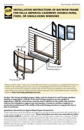
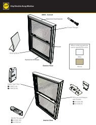
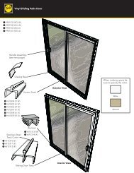
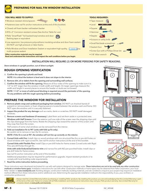
RESISTIVE BARRIERRESISTIVE BARRIERRESISTIVE BARRIERRESISTIVE BARRIERSill Flashing Tape #1Sill Flashing Tape #2Sill Flashing Tape #1Sill Flashing Tape #2Water Resistive BarrierSheathingWater Resistive BarrierFramingSheathingFramingRESISTIVE BARRIERNEW CONSTRUCTION <strong>INSTALLATION</strong> WITH <strong>NAIL</strong> <strong>FIN</strong> AFTER BUILDING WRAPRESISTIVE BARRIERRESISTIVE BARRIERRESISTIVE BARRIERRESISTIVE BARRIERWATER RESISTIVE BARRIERRESISTIVE BARRIER RESISTIVE BARRIERRESISTIVE BARRIERRESISTIVE BARRIER RESISTIVE BARRIERRESISTIVE BARRIERRESISTIVE BARRIERRESISTIVE BARRIERRESISTIVE BARRIERWATER RESISTIVE BARRIERRESISTIVE BARRIERRESISTIVE BARRIERRESISTIVE BARRIERRESISTIVE BARRIERRESISTIVE BARRIERWATER RESISTIVE BARRIERRESISTIVE BARRIERRESISTIVE BARRIERRESISTIVE BARRIERRESISTIVE BARRIERWATER RESISTIVE BARRIERRESISTIVE BARRIERWATER RESISTIVE BARRIERRESISTIVE BARRIERRESISTIVE BARRIERWindow TopNailing FinRESISTIVE BARRIERWATER RESISTIVE BARRIERRESISTIVE BARRIERRESISTIVE BARRIERRESISTIVE BARRIERRESISTIVE BARRIERWindow BottomFinCornerWindow TopNailing FinWATER RESISTIVE BARRIERWATER RESISTIVE BARRIERRESISTIVE BARRIERFinCornerWindow Bottom1 PREPARE THE OPENING 2 SETTING AND FASTENING THE <strong>WINDOW</strong>Refer to the nail fin installation preparation section at the beginning ofthis booklet.A. Cut the building wrap.Refer to the diagram forother window shapes onthe next page.B. Fold the building wrap inat the jambs and staple it inplace. Fold the top flap upand temporarily fasten withflashing tape.NF – 4RESISTIVE BARRIERRESISTIVE BARRIERRESISTIVE BARRIERRESISTIVE BARRIERRESISTIVE BARRIERRESISTIVE BARRIERWater Resistive Barrier1st cut6” 6”1C1ARESISTIVE BARRIERWATAER RESISTIVE BARRIER3rd cutRevised 10/17/2014RESISTIVE BARRIERRESISTIVE BARRIER2ndcutRESISTIVE BARRIER RESISTIVE BARRIERRESISTIVE BARRIER RESISTIVE BARRIERExterior1B 1DWater Resistive Barrier CornerFlashing1 st cutTapeCornerFlashing6”2 nd Tape 6”cutTopFlashing1C1A TapeSideFlashing 3 rd cutSideTapeSideFlashingTapeRESISTIVE BARRIERRESISTIVE BARRIERC. Cut 2 pieces of flashing tape 12" longer thanopening width.D. Apply sill flashing tape #1 at the sill extending 1" tothe exterior and 6" up each jamb.E. Cut 1" wide tabs at each corner by tearing the foil1/2" each way from corner.F. Apply sill flashing tape #2 overlapping tape #1 by1" minimum.NOTE: Press all tape down firmly.G. Install and level sill shims. Place 1" wide x 1/4" to3/8" thick shims 1/2" from each side. Keep shimsback 1/2" from interior face of window. Placeadditional shims under each mullion and slidingwindow interlocker.For vinyl windows, add shims so maximum spacingis 18".H. Attach shims to prevent movement after they arelevel.NOTE: Improper placement of shims may result inbowing the bottom of the window.RESISTIVE BARRIERRESISTIVE BARRIERWATAER RESISTIVE BARRIER1"6"1D 1FRESISTIVE BARRIERRESISTIVE BARRIERRESISTIVE BARRIER1/2"1"Exterior1/2"1B 1DFlashingTape B. Drive two fasteners, one near each end of the top nailing fin.SideFlashing (See nail fin anchor instructions at the end of this booklet)Tape C. Plumb and square the windowInteriorusing shims at the locations1”shown. Adjust shims to plumband square the window. Keep2Cshims 1/2" short of windowframe depth.2CMidNOTE: DO NOT shim abovethe window. Additionalshims are required at screw1”locations for large units and<strong>com</strong>binations. See the nail finInterioranchor instructions at the end of this booklet.D. Check the window placement by measuring from 2C1C the interior surface of the window frame or jamb1Eextension to the interior surfaceof the wall for consistency. If thedimensions are not equal, confirm 2Dthe fins are folded fully to 90º (ifapplicable).E. Drive two fasteners, one neareach end of the sill nailing fin.F. Check window operation.1E 1G1G 2A© 2014 <strong>Pella</strong> CorporationA. Insert the window into the opening on the sill spacers. Center thewindow between jambs.2A2 ndCornerFlashingTapeCornerFlashingTapeTopFlashingTape2B 2E2B2EInterior ViewFor windows over 53” tall.Vent awning and casement: See lock lever and crank handle instructionsat the end of this instruction. Lift the lock lever and turn the crank handleto open the window. Remove the shipping spacers. Open and close thewindow to test for proper operation.Double Hung: Cut the checkrail bands (if applicable) and removeshipping spacers. Open, close and tilt the sashes to test for properoperation. Check for equal sash to frame reveal from top to bottom.NOTE: Adjust shims to correct any issues with plumb, square, operationor reveal.G. Close and lock the window.H. Finish driving fasteners into the nailing fin. Refer to the nail fin anchorinstructions at the end of this booklet.NC_NFAWmm1INCHES2 32 0 3 0 4 0 5 0 6 0 7 0
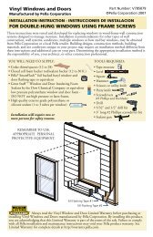
NEW CONSTRUCTION <strong>INSTALLATION</strong> WITH <strong>NAIL</strong> <strong>FIN</strong> AFTER BUILDING WRAP (CONTINUED)Corner CornerFlashing FlashingTape TapeCorner CornerFlashing FlashingTape TapeTop TopFlashing FlashingTape TapeSide SideFlashing FlashingTape TapeSide SideFlashing FlashingTape Tape3 INTEGRATING WITH THE BUILDING WRAPNOTE: Apply flashing tape 1/2"onto frame cladding with fold-up orslide-in fins. Pre-fold flashing tapeat 1/2" to assist with application.For siding less than 1/2" thick,adjust the placement of the tape toallow the exterior sealant to coverthe tape edge.FlashingTapeC. Apply top flashing tape.Rectangular Units: Cut one piece offlashing tape to extend 1" past both sideflashing tapes.3C 3B3C 3B1"Curved and angle top units without pre-applied fin corners:A. Cut four 1-1/2" long pieces offlashing tape.3AApply one to each end of sillfin to extend it 1-1/2" past eachjamb.1 stApply one to the bottom end ofeach jamb fin beginning 1-1/2"from the end of the fin and 3Alapping over the first piece offlashing tape.2 ndCurved Top Units: Using several shortpieces, start taping from the sides of thewindow working towards the peak. Cut eachpiece short enough so each piece overlaps theprevious piece. Tighter curved frames will requireshorter pieces of tape.Exterior3CExteriorB. Apply straight side flashing tape. Cut two piecesof flashing tape 4" taller than straight sides. Applytape over the fin and onto weather resistive barrier.Extend tape 2" above and below straight sides.Angle top Units: On the short side, do not allowthe side tape to extend higher than what the toptape will cover.3BBuilding Wrap Cutting Patterns for Window ShapesNOTE: DO NOT TAPE OVER BOTTOM <strong>NAIL</strong>ING <strong>FIN</strong>.D. Fold down top flap of weather resistive barrier.E. Apply flashing tape to top diagonal cuts. Cut pieces of flashing tape atleast 1" longer than each diagonal cut. Lap tape 1" past end of cut ontoweather barrier. Overlap multiple pieces of tape by 1" when necessary.NOTE: PRESS ALL FLASHING TAPE DOWN FIRMLY.3EExterior3E3E 4D3E4DExterior View3E4COvalArch HeadFull CircleDog HouseQuarter CircleTrapezoid RectangleHalf CircleRight TriangleCircle HeadOctagonF. Install interior sealant. Refer to the interior sealant instructions at the endof this booklet.G. Install head flashing, properly incorporating it with the siding and buildingwrap according to applicable code requirements.H. Install exterior sealant. (After wall cladding is installed) Refer to theexterior sealant instructions at the end of this booklet.NF – 5Revised 10/17/2014© 2014 <strong>Pella</strong> CorporationNC_NFAW
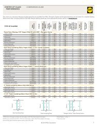
<strong>NAIL</strong> <strong>FIN</strong> <strong>WINDOW</strong> ANCHOR INSTRUCTIONSNote: Standard performance only. Additional anchoring may be required for performance upgrade, impact resistant products or to <strong>com</strong>ply with localbuilding code requirements.PLACE FASTENERS AT THE LOCATIONS INDICATED.EEEVERYSEAnchor clusters, see table.EEVERYSE250 Series5/32" drill3/8" drill forclearance holeEVERYSESingle-, Double-HungEXTERIORSliding Window XO / OXEHEAD5/32"EVERYSE7/8"1/2"3/8”1/2” 1/2”Sill accessory grooveAttachment clipHP Nail Fin Framewith Frame FillerJAMBSelf Adhesive Plastic SpacerAccessory GroovesEEVERYSEEEVERYSEAttachment clipEEVERYSEEVERYSClip Installation for MullionsDOUBLE-HUNG <strong>WINDOW</strong> SILLDrill (2) 5/32" holes or (3) for15 series units 3/8" from theedge in each clip.SW Vent TrackSW Pocket FillerESliding Window XOXEPlugCasementSelf-adhesive spacerHP Frame FillerPocket Cover RemovalENCOMPASS BY PELLA®/THERMASTAR BY PELLA® / PELLA® 250 SERIES AND PELLA® 350 SERIES <strong>WINDOW</strong>SProductEn<strong>com</strong>pass andThermaStar Windows250 SeriesWindows250 SeriesSH/SW/FX250 SeriesDH350 SeriesSH and DH350 Series 2 PanelSliding Windows350 Series 3 PanelSliding Windows350 SeriesCM, AW, FX350 Series FXCompositesPGRatingMax FrameWidth(inches)Max FrameHeight(inches)EdgeSpacing(E)Max.IntermediateSpacing (S)Anchor TypeWood *Anchor Cluster< 50 Any Any Every Other Pre-Punched 2" 11 Ga. Roofing Nail None50 Any Any Every Pre-Punched Hole #8 x 2" Screw with Washer None< 50 Any AnyEvery Other Pre-PunchedHole1.5" 11 Ga. Roofing Nail50 Any Any Every Pre-Punched Hole 1.5" 11 Ga. Roofing Nail50 Any Any Every Pre-Punched Hole #10 x 2" Screw with WasherDH/SH/FX: 5 nails 2" apart at Checkrails3 - #10 x 2" screws, 2" apart at Mullion EndsSW: 3 - #10 x 2" screws, 2" apart at Checkrailsand Mullion Ends** 3 jamb frame screws, 4" apart at Checkrails3 - #10x2" screws, 2" apart at Mullion Ends30 40" 63" 6" 8" 1.5" 11 Ga. Roofing Nail None40 40" 63" 6" 8" 1.5" 11 Ga. Roofing Nail 5 nails, 2" apart at Checkrails+40/-60 Any Any 6" 8" 1.5" 11 Ga. Roofing Nail5 nails, 2" apart at Checkrailsand Mullion Ends30 76" 48" 6" 8" 1.5" 11 Ga. Roofing Nail None40 76" 62" 6" 8" 1.5" 11 Ga. Roofing Nail 5 nails, 2 inches apart Meeting Stiles+40/-60 76" 72" 6" 8" #10 x 2" Screw with Washer 3 Screws, 2" apart at Meeting Stiles30 123" 48" 6" 8" 1.5" 11 Ga. Roofing Nail None40 123" 62" 6" 8" 1.5" 11 Ga. Roofing Nail 5 nails, 2" apart at Meeting StilesAllOtherAny Any 6" 8" #10 x 2" Screw with Washer 5 Screws, 2" apart at Meeting Stiles40 Any Any 6" 8" 1.5" 11 Ga. Roofing Nail None60 Any Any 4" 4" 1.5" 11 Ga. Roofing Nail NoneAll Any Any 4" 4" 1.5" 11 Ga. Roofing Nail 5 nails, 2" apart at Mullion Ends* For light gauge steel framing, use #10 self-drilling modified truss head screws.** High Performance Frame Fillers are required at each jamb anchor location.NOTE: Do not over-drive fasteners, but allow for movement of building materials.NF – 14Revised 10/17/2014© 2014 <strong>Pella</strong> CorporationRefer to the supplemental instruction included with the unit for securing mullion endanchors (if applicable).When screws are used in the Nail-Fin, a 1" fender washer is required at each screwanchor location.NC_NFAW
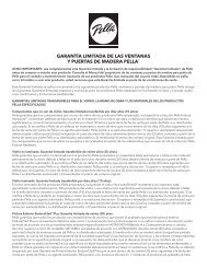
UNITS WITH WIDE PELLA® ENDURACLAD® EXTERIOR TRIM WITH NARROW <strong>FIN</strong>S AND NO PRE-PUNCHED HOLES ANCHOR INSTRUCTIONSNote: Standard performance only. Additional anchoring may be required for performance upgrade, impact resistant products or to <strong>com</strong>ply with localbuilding code requirements.Units with narrow fins and NO pre-punched holes must be anchored using frame screws or installation clips. These fins are for flashing purposes only.PLACE FRAME SCREWS OR CLIPS AT THE LOCATIONS INDICATEDEEVERYSM2 M2M1 M1SEEEVERYSEEEEEVERYSEEM2 M2 EVERYE S SM1 M1M2M1M2M1SEESM2M1M1M2EVERYSM1M1M2M2EVERYSEVERYSEVERYSEVERYSEEEEARCHITECT SERIES® (850), DESIGNER SERIES® (750) AND PELLA® PROLINE (450)<strong>WINDOW</strong> ANCHOR SPACING INSTRUCTIONSProductEdgeSpacing(E)Max.IntermediateSpacing(S)FirstMullionAnchor(M1)SecondMullionAnchor(M2)FastenerWood **Special NotesCasement / Awning 6" 16" 3"* 6" #8x3" Finish ScrewDouble- orSingle- Hung6" 16" 3"* 6" #8x3" Finish ScrewFixed Frame 6" 16" 3"* 6" #8x3" Finish Screw** = For light gauge steel framing, use #10 self-drilling/self-tapping screws; For concrete or masonry, use 3/16"masonry screws with 1-1/4" minimum embedment.* M1 anchor required if design pressure exceeds 20 psf.Exterior trim with narrow finPILOT HOLE LOCATIONS AND SIZESCasement HeadDouble-Hung HeadDouble-Hung HeadClad Frame HeadPrecision Fit ® Clad Frame1/2"Drill 1/8"clearance holeDrill 1/8"clearance hole1"Drill 1/8"clearance holeHeadblocking3/8"Casement JambDouble-Hung JambDouble-Hung JambDrill 1/8"clearance hole1"#6 x 1-1/2" screw1/4"Drill 1/8"clearance holeDrill 1/8"clearance holeClad Frame Sill#6 x 5/8” corrosionresistant screws5/8"Sillblocking6“ from endDrill 1/8"clearance holeDrill 1/8"clearance holeDrill 1/8"clearance holeLip1/2"Casement SillDouble-Hung SillDouble-Hung SillNF – 16Revised 10/17/2014© 2014 <strong>Pella</strong> CorporationNC_NFAW
INTERIOR AND EXTERIOR SEALANTInterior Sealant InstructionsCAUTION: Use low pressure polyurethane window and door insulating foams. Follow thedirections on the can. Do not use high pressure or latex foams.A. Insert the nozzle or straw between the rough opening and window frame from the interior. Use apliers (if necessary) to <strong>com</strong>press the end of a straw tube to allow it to fit in tight openings.B. Place a 1" deep bead of foam approximately 1" from the interior of the frame to allow forexpansion. DO NOT fill the entire depth of the rough opening cavity.NOTE: Apply foam between the frame and rough opening, NOT between jamb extensions andthe rough opening.C. To ensure a continuous interior seal, apply sealant over the interior surface of any shims or clipsinterrupting the foam seal.Backer rod (as necessary) and sealant can be used in place of the low expansion foam to createthe interior seal. However, foam has greater insulating properties. Fiberglass batt or similarinsulation is not re<strong>com</strong>mended as it can absorb water and does not act as an air seal.NOTE: Use a low odor, paintable sealant such as <strong>Pella</strong> Window and Door Installation Sealant.Re-check window operation and remove shipping spacers after foam installation. Excess foammay be removed with a serrated knife after it cures.InteriorAExterior Sealant InstructionsCAUTION: Use a high quality, multi-purpose exterior sealant such as <strong>Pella</strong> Window and Door InstallationSealant. Follow the directions on the cartridge.When applying siding, brick veneer , flashing, or other exterior finish materials, leave adequate spacebetween the window frame and the material for sealant application.AA. Insert backer rod 3/8" deep in the space around the window. Backer rod adds shape and controls thedepth of the sealant line.B. Apply a continuous bead of sealant to the entire perimeter of the window.C. Shape, tool and clean excess sealant. When finished, the sealant should be the shape of an hourglass.BNOTE: The siding details below apply to windows without a J-mould as part of the frame. The J-mouldframe is only intended for vinyl or metal sidings where the siding is extended behind the J-mouldportion of the frame. The J-mould should be removed and replaced with backer rod and sealant with allother siding or trim types.BRICK VENEERSIDINGSIDINGWITH TRIMInsulatingFoamBacker Rod andSealant typical3/8" ClearanceAccessory GroovePerimeter Sealantmust extend to roomside of AccessoryGroove.InsulatingFoamSealant typical1/8" ClearanceAccessoryGrooveInsulatingFoamSealant typical3/8" ClearanceAccessory GroovePerimeter Sealantmust extend to roomside of AccessoryGroove.3/8"1/8"3/8"3/8"Min.3/8"Min.NF – 17Revised 10/17/2014© 2014 <strong>Pella</strong> CorporationNC_NFAW
INSTALLING ROTO COVER AND CRANKLOCK LEVER <strong>INSTALLATION</strong> AND REMOVALNote: Finish the interior of the window and allowthe window to dry before proceeding with theseinstructions. (To open the window for finishing, partiallyinsert the lock handle into the jamb, unlock the unit,temporarily attach the crank handle and turn to open.)A. Place the cover over the operator stud and snap intoplace. Position the pocket end of the cover into place.Note: If the cover does not have the screw hole, applypressure on the pocket end of the cover to snap thecover into place and proceed to step C.B. Insert the provided screw into the hole in the bottomof the pocket. Use a # 1 Phillips screwdriver to securethe pocket screw snug against the bottom of the pocketto avoid scratching the crank handle knob. DO NOTover tighten.C. Use a medium size flat-blade screwdriver to loosen theset screw in the crank handle.D. Slide the crank handle onto the stud. Unlock, openwindow, then close and lock window.E. Fold the crank handle down and check alignment ofknob with the pocket.Note: You may need to adjust the crank position on thestud until the correct alignment is achieved.F. Open the crank and tighten the set screw.G. After the final installation, fold the crank over and snapthe knob into the pocket.Note: Even with the window open the crank canbe folded to avoid interferring with the windowtreatments.ABPocket EndScrew HoleOperator StudCrank HandleOperator StudSet ScrewKnobDPocketCEA. Unlock and open the window.B. Place the lock lever in the lockedposition.C. From the exterior of the window,Einsert a small flat-blade screwdriverinto the slot behind the lock lever.D. Pry the cam away from the sideof the window by rotating thescrewdriver a quarter turn. This willrelease the hook in the lever from theB Interiorcam hook.Exterior CE. Remove the lock lever by pulling itInterior Frame Covertoward the interior of the building.removed to showF. To install a lock lever, hold it in theorientation oflock position and insert it, from thescrewdriver betweenthe lever and cam.interior, into the slot until it snapsinto the cam.B InteriorExteriorC FEDInteriorExterior Finish of Existing Frame (Pocket Replacement)It is the responsibility of the homeowner, contractor or installer to ensure any exposed unfinished wood is covered or finished. Possible methods include, however are not limited to,covering with aluminum coil stock or painting.EDCleaning InstructionsGLASS—Remove any protective film and labels and clean the glass, using a soft, clean, grit-free cloth and mild soap or detergent. Be sure to remove all liquid by wiping dry or use aclean squeegee.<strong>Pella</strong>® ALUMINUM CLAD OR IMPERVIA FRAMES—The interior and exterior frame and sash are protected with a tough factory finish. Clean this surface with mild soap and water.Stubborn stains and deposits may be removed with mineral spirits. DO NOT use abrasives. DO NOT scrape or use tools that might damage the surface.En<strong>com</strong>pass by <strong>Pella</strong>®/Thermastar by <strong>Pella</strong>® and <strong>Pella</strong>® 350 Series Windows FRAMES—The vinyl frame may be cleaned using the same method as the glass. For stubborn dirt, a “nonabrasive"cleaner such as Bon-Ami® or Soft Scrub® may be used. Do not use solvents such as mineral spirits, toluene, xylene, naphtha or muriatic acid as they can dull the finish,soften the vinyl and/or cause failure of the insulated unit seal. Keep door tracks clear of dirt and debris. Keep weep holes open and clear of obstructions.Use of inappropriate solvents, brickwash or cleaning chemicals will cause adverse reactions with window and door materials and voids the Limited Warranty.Interior Finish (Wood Windows)If products cannot be finished immediately, cover with clear plastic to protect from dirt, damage and moisture. Remove any construction residue before finishing. Sand all woodsurfaces lightly with 180 grit or finer sandpaper. DO NOT use steel wool. BE CAREFUL NOT TO SCRATCH THE GLASS. Remove sanding dust. <strong>Pella</strong> products must be finished per thebelow instructions; failure to follow these instructions voids the Limited Warranty.• On casement and awnings, it is optional to paint, stain or finish the vertical and horizontal sash edges.• On single-hungs and double-hungs, do not paint, stain or finish the vertical sash edges, any finish on the vertical sash edges may cause the sash to stick; it is optional to paint,stain or finish the horizontal sash edges.Note: To maintain proper product performance do not paint, finish or remove the weatherstripping, mohair dust pads, gaskets or vinyl parts. Air and water leakage willresult if these parts are removed. After finishing, allow venting windows and doors to dry <strong>com</strong>pletely before closing them.<strong>Pella</strong> Corporation is not responsible for interior paint and stain finish imperfections for any product that is not factory-applied by <strong>Pella</strong> Corporation. For additional information onfinishing see the <strong>Pella</strong> Owner’s Manual or go to www.pella.<strong>com</strong>.Care and MaintenanceCare and maintenance information is available by contacting your local <strong>Pella</strong> retailer. This information is also available at www.pella.<strong>com</strong>.IMPORTANT NOTICEBecause all construction must anticipate some water infiltration, it is important that the wall system be designed and constructed to properly manage moisture. <strong>Pella</strong> Corporationis not responsible for claims or damages caused by anticipated and unanticipated water infiltration; deficiencies in building design, construction and maintenance; failure to install<strong>Pella</strong> products in accordance with <strong>Pella</strong>’s installation instructions; or the use of <strong>Pella</strong> products in wall systems which do not allow for proper management of moisture within the wallsystems. The determination of the suitability of all building <strong>com</strong>ponents, including the use of <strong>Pella</strong> products, as well as the design and installation of flashing and sealing systems arethe responsibility of the Buyer or User, the architect, contractor, installer, or other construction professional and are not the responsibility of <strong>Pella</strong>.<strong>Pella</strong> products should not be used in barrier wall systems which do not allow for proper management of moisture within the wall systems, such as barrier Exterior Insulation andFinish Systems (EIFS) (also known as synthetic stucco) or other non-water managed systems. Except in the states of California, New Mexico, Arizona, Nevada, Utah and Colorado,<strong>Pella</strong> makes no warranty of any kind on and assumes no responsibility for <strong>Pella</strong> windows and doors installed in barrier wall systems. In the states listed above, the installation of <strong>Pella</strong>Products in barrier wall or similar systems must be in accordance with <strong>Pella</strong>’s installation instructions.Product modifications that are not approved by <strong>Pella</strong> Corporation will void the warranty.NF – 18Revised 10/17/2014© 2014 <strong>Pella</strong> CorporationExteriorFNC_NFAWInterior