8750-1 - KTH Sales Inc.
8750-1 - KTH Sales Inc.
8750-1 - KTH Sales Inc.

Create successful ePaper yourself
Turn your PDF publications into a flip-book with our unique Google optimized e-Paper software.
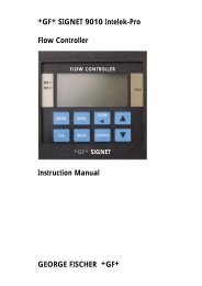
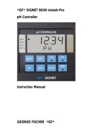
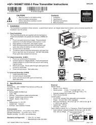
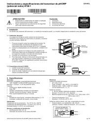
+GF+ SIGNET <strong>8750</strong>-1 pH/ORP Transmitter InstructionsENGLISH3-<strong>8750</strong>.090-1A-9/99 EnglishCAUTION!• Remove power to unit before wiringinput and output connections.• Follow instructions carefully to avoidpersonal injury.Contents1. Installation2. Specifications3. Electrical Connections4. Menu FunctionspH/ORP10.20 pH25.0°CRelay 1 Relay 2ENTER1. InstallationThe transmitter is available in two versions: a panel mount version, and an integral version for installation near the sensor (universalassembly)gasketpanelterminals1.1 Panel InstallationThe Panel Mounting kits are supplied with the hardware toinstall instrumentation into panels and maintain a NEMA 4Xseal.1. Punch out panel and de-burr edges. Recommendedclearance on all sides between instruments is 1 inch.2. Place gasket on instrument, and install in panel.3. Slide mounting bracket over back of instrument untilquick-clips snap into latches on side of instrument.4. Connect wires to terminals.5. To remove, secure instrument temporarily with tape fromfront or grip from rear of instrument. DO NOT RELEASE.Press quick-clips outward and remove.1.2 Universal Assembly (3-8050)1. Install transmitter base2. Connect wires to transmitter.3. Close unit and secure with push and twist lock.Seal cable entry.latchwiresmountingbracketquick-clipseal2. SpecificationsGeneralCompatible electrodes: +GF+ SIGNET 3-2720 pH/ORPPreamplifier/ElectrodeAccuracy: ± 0.03 pH, ± 2 mV' ORPEnclosure:• Rating: NEMA 4X/IP65 front• Case: PBT• Window: Polyurethane coated polycarbonate• Keypad: Sealed 4-key silicone rubber• Weight: Approx. 325g (12 oz.)Display:• Alphanumeric 2 x 16 LCD• Contrast: User selected, 5 levels• Update rate: 1 secondEnvironmentalOperating temperature: -10 to 70°C (14 to 158°F)Storage temperature: -15 to 80°C (5 to 176°F)Relative humidity: 0 to 95%, non-condensingStandards and Approvals• CSA, CE, UL listed• Manufactured under ISO 9001+GF+ SIGNET <strong>8750</strong>-1 pH/ORP Transmitter InstructionsElectricalSensor input range:• pH: 0.00 to 14.00 pH• temp. 3K Balco, -25 to 120°C (-13 to 248°F)• ORP: -1000 to +2000 mV, isolated(10KΩ I.D. resistance T+, T-)Current output:• 4 to 20 mA, isolated, fully adjustable and reversible• Power: 12 to 24 VDC ±5%, regulated• Max loop impedance: 50 Ω max. @ 12 V, 325 Ω max. @ 18 V,600 Ω max. @ 24 V• Update rate: 0.5 seconds• Accuracy: ±0.03 mA @ 25°C, 24 VOpen-collector output: Hi, Lo, Pulse Programmable• Open-collector, isolated, 50 mA sink or source, 30 VDC max.pull-up voltageInternal open-collectoroutput circuitS 15ΩIsolationD4 Output -3 Output +page 1 of 8
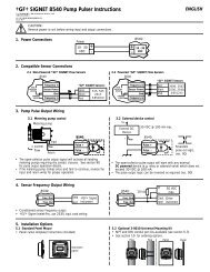
DimensionsPanel Mount96mm (3.8 in.)Field Mount96 mm (3.8 in.)Panel Cutout96 mm(3.8 in.)OptionalRear Cover92 x 92 mm(+ 0.8, - 0 mm)3.6 x 3.6 in.(+0.031, -0 in.)96 mm(3.8 in.)82 mm(3.23 in.)41 mm(1.6 in.)56 mm(2.2 in.)97 mm(3.8 in.)106 mm(4.18 in.)3. Electrical ConnectionsCaution: Failure to fully open terminal jaws before removing wire may permanentlydamage instrument.Wiring Procedure1. Remove 0.5 - 0.625 in. (13-16 mm) of insulation from wire end.2. Press the orange terminal lever downward with a small screwdriver to openterminal jaws.3. Insert exposed (non-insulated) wire end in terminal hole until it bottoms out.4. Release orange terminal lever to secure wire in place. Gently pull on each wireto ensure a good connection.21Wiring Removal Procedure1. Press the orange terminal lever downward with a small screwdriver to openterminal jaws.2. When fully open, remove wire from terminal.TerminalsSystem Power/Loop1. System Power/Loop +2. System Power/Loop -Description12-24 VDC ±5%, system power and current loop connections.Max. loop impedence: 50 Ω max. @ 12 V, 325 Ω max. @ 18 V,600 Ω max. @ 24 V12Temp -(WHITE)Open Collector Output3. Output +4. Output -Preamplifier/Sensor Input5. Red (V+)6. Black (V-)7. Shield (Sensr GND)8. Earth GND9. Brown (mV input)10. Blue (ISO GND)11. Green (Temp)12. White (Temp)Open-collector transistor output programmable as:• High/Low alarm with adjustable hysteresis• Proportional pulse output• Disable (Off) selectionPreamplifier positivePreamplifier negativePreamplifier shieldConnect if electrical noise is presentPreamplifier mV outputPreamplifier groundTC element (3K Balco pH, 10KΩ ORP ID resistance)TC element (3K Balco pH, 10KΩ ORP ID resistance)21 4System PwrLoop -System PwrLoop +3Output -Output +111098765Temp +(GREEN)Iso. GND(BLUE)mV Input(BROWN)EarthGNDSensr Gnd(SHIELD)V-(BLACK)V+(RED)Wiring Tips:• Do not route sensor cable in conduit containing AC power wiring - electricalnoise may interfere with sensor signal.• Routing sensor cabling in grounded metal conduit may prevent moisturedamage, electrical noise, and mechanical damage.• Seal cable entry points to prevent moisture damage.• When placing two wire ends into a single terminal, solder or crimp endstogether.page 2 of 8+GF+ SIGNET <strong>8750</strong>-1 pH/ORP Transmitter Instructions
3.1 System Power/Loop ConnectionsStand-alone application, no current loop usedConnection to a PLC with built-in power supplyTransmitterSys. Pwr.Loop -Sys. Pwr.Loop +Terminals21-+Power SupplyDC 12 - 24 VPowerSupplyPowerSupplyTransmitterSys. Pwr.Loop -Sys. Pwr.Loop +Terminals21Internal PLCConnectionPLC-+-+TerminalsPower SupplyGroundPowerSupplyLoop Input4-20 mALoop Input4-20 mAConnection to a PLC/Recorder, separate supplyExample: Two transmitter connected to PLC/Recorderwith separate power supplyTransmitter-+DC 12 - 24 VPowerSupplyPowerSupplyTransmitter 1Sys. Pwr.Loop -Sys. Pwr.Loop +21-+DC 12 - 24 VPowerSupplyPowerSupplySys. Pwr.Loop -Sys. Pwr.Loop +Terminals21PLC or Recorder-+Loop Input4-20 mA inLoop Input4-20 mA inTransmitter 2Sys. Pwr.Loop -Sys. Pwr.Loop +21PLC or Recorder-+-+Channel 14-20 mA inChannel 14-20 mA inChannel 24-20 mA inChannel 24-20 mA in3.2 Sensor Input ConnectionsWiring Tip:Do not route sensor cable inany conduit containing ACpower wiring - electrical noisemay interfere with the signal.Terminals*12111098765White (Temp)Green (Temp)Blue (ISO GND)Brown (mV input)Silver (Shield)Black (V-)Red (V+)* (connection of terminal 8 to Earth GNDmay reduce electrical interference)Preamp:+GF+ SIGNET 2720pH Electrodes+GF+ SIGNET 2714, 2714-HF+GF+ SIGNET 2716ORP Electrodes:+GF+ SIGNET 2715+GF+ SIGNET 27173.3 Output Functions• Low: Output triggers when process variable is less thansetpoint.• High: Output triggers when process variable is higher thansetpoint.Example: In Low Alarm Mode Operation, the output becomesactive when the process drops below the setpoint, andbecomes inactive when the process rises above the setpointplus hysteresis. The opposite is true for High Alarm Mode.HysteresisSetpointProcessOutput ActiveOutput Inactive+GF+ SIGNET <strong>8750</strong>-1 pH/ORP Transmitter InstructionsTime• Disable: Disables output pulse.• Proportional Pulse Mode OperationThe output emits a 100 mS pulse (simulated contact closure) atrate defined by the Output, Pulse Range, Output Rate, and theprocess condition (0 to 400 pulses/minute, as programmed)Example: As the process falls below 10 the output will startpulsing in relation to the process value, the max pulse endpointand the programmed pulses/min. Pulse rate will increase asthe process approaches the programmed endpoint.10 = 1 pulses/min.7.5 = 50 pulses/min.5 = 100 pulses/min.Pulse rate5Relay 1or Relay 2100 pulsesOutput1 Rate:100 Pulses/min>Relay 1: Pulse10.0000→5.0000>10Start→max. pulse endpoint0 pulsesProcess variablepage 3 of 8
4. Menu Functions - pHVIEW Menu: is displayed during standard operation.• Press UP or DOWN buttons to view process parameters.• Press UP and DOWN buttons at the same time, to exit anyother display and return to VIEW menu.• Display will return to VIEW menu in 10 minutes unless a keyis pressed.CALIBRATE Menu: contains display setup and outputparameters. A security code feature prevents unauthorizedtampering. To access CALIBRATE menu:• Press ENTER button for 2 seconds to display:• Press UP, UP, UP, DOWN buttons in sequenceto display:CALIBRATE: ----Enter Key CodeCALIBRATE: ---- XXXXEnter Key CodeOPTIONS Menu: contains setup and display features for minordisplay or output adjustments. To access OPTIONS menu:• Press ENTER button for 5 seconds to display:• Press UP, UP, UP, DOWN buttons in sequenceto display:OPTIONS: ----Enter Key CodeOPTIONS: XXXX ----Enter Key CodeMenu Tips• Right button scrolls to right, from top to bottom row, and allowsediting when ">" symbol is shown.• In CALIBRATE or OPTIONS menus, the transmitter willcontinue to measure and control outputs. When > is pressed,the input value is held at the last measured process value.• When sensor is not connected, unit will display CHECKSENSOR and any output controlled by sensor will be at 3.6 mAor OFF.ExampleTo change date, first enter CALIBRATE menu (Press ENTER button for 2 seconds; Press UP, UP, UP, DOWN buttons in sequence)Once in CALIBRATE menu, press UP button 1 time.1. Display shows rightarrow2. Press RIGHT buttonto display "01" blinking3. Press buttons to scrollthrough numbers.4. Press ENTER buttonto save5. Display now readsnew dateLAST CAL:01-01-99 >LAST CAL:01-01-99LAST CAL:08-01-99SAVINGLAST CAL:08-01-99+GF+ SIGNET+GF+ SIGNET +GF+ SIGNET+GF+ SIGNET +GF+ SIGNETENTERENTERENTERENTERENTERMenu Functions - pHView Menu Range Calibrate Menu Range Preset Options Menu Range PresetpH: 0-15 pH Set: ± 25°C 3KΩ = Contrast: 1-5 3Temp: -38 - 140°C Temperature > 25°C Level >Input: -999 Set: 0-14 7.00 pH Averaging: Off OffmV to Standard > pH (0 offset) Off > Low (4secs)+1999 High (8secs)Loop Output: 4-20 mA Set: 0-14 4.00 pH Output Active: Low LowmA Slope > pH (ideal scope) Low > HighLast Cal: 00-00-00 Loop Range: pH 0-14 pH 14.00 Temp Display: °C °CDate to 0.00 > 14.00 > °C > °F39-39-99 (4mA) (20 mA)Easy pH 4,7,10 Output Source: pH or pH Loop Adjust: 3.8 to 4.00Cal: > buffers pH > Temp. 4.00 mA > 5.0 mA mAOutput Mode: Off Off Loop Adjust: 19.0 to 20.00Off > Low 20.00 mA > 21.0 mA mAHighPulseLow or High Test Loop: 0-14 pH processselected > 4-20 mA valueOutput Setpoint: 0-14 4.00 pH Test Output: On or last4.00 pH > pH > Off stateOutput Hys: 0-14 0.5 pH0.50 pH > pHPulse SelectedOutput Range: 0-14 pH 4-8 pH4.00 > 8.00 >(Start>Endpoint)Output Rate: 0-400 120120 pulses/min > pulses/min pulses/minLast Cal: 00-00-00 to 01-01-9901-01-99 > 39-39-99page 4 of 8+GF+ SIGNET <strong>8750</strong>-1 pH/ORP Transmitter Instructions
4. Menu Functions - ORPVIEW Menu: is displayed during standard operation.• Press UP or DOWN buttons to view process parameters.• Press UP and DOWN buttons at the same time, to exit anyother display and return to VIEW menu.• Display will return to VIEW menu in 10 minutes unless a keyis pressed.CALIBRATE Menu: contains display setup and outputparameters. A security code feature prevents unauthorizedtampering. To access CALIBRATE menu:• Press ENTER button for 2 seconds to display:• Press UP, UP, UP, DOWN buttons in sequenceto display:CALIBRATE: ----Enter Key CodeCALIBRATE: ---- XXXXEnter Key CodeOPTIONS Menu: contains setup and display features for minordisplay or output adjustments. To access OPTIONS menu:• Press ENTER button for 5 seconds to display:• Press UP, UP, UP, DOWN buttons in sequenceto display:OPTIONS: ----Enter Key CodeOPTIONS: XXXX ----Enter Key CodeMenu Tips• Right button scrolls to right, from top to bottom row, and allowsediting when ">" symbol is shown.• In CALIBRATE or OPTIONS menus, the transmitter willcontinue to measure and control outputs. When > is pressed,the input value is held at the last measured process value.• When sensor is not connected, unit will display CHECKSENSOR and any output controlled by sensor will be at 3.6 mAor OFF.ExampleTo change date, first enter CALIBRATE menu (Press ENTER button for 2 seconds; Press UP, UP, UP, DOWN buttons in sequence)Once in CALIBRATE menu, press UP button 1 time.1. Display shows rightarrow2. Press RIGHT buttonto display "01" blinking3. Press buttons to scrollthrough numbers.4. Press ENTER buttonto save5. Display now readsnew dateLAST CAL:01-01-99 >LAST CAL:01-01-99LAST CAL:08-01-99SAVINGLAST CAL:08-01-99+GF+ SIGNET+GF+ SIGNET +GF+ SIGNET+GF+ SIGNET +GF+ SIGNETENTERENTERENTERENTERENTERMenu Functions - ORPView Menu Range Calibrate Menu Range Preset Options Menu Range PresetORP mV: -1000 to Set: -1000 to N/A Contrast: 1-5 3Input mV: +2000 mV Standard > +2000 mV Level >Loop Output: 4-20 mA Set: -1000 to N/A Averaging: Off OffmA Slope > +2000 mV Off > Low (4secs)Last Cal: 00-00-00 High (8secs)Date 39-39-99 Loop Range:mV -1000 to -1000 to Output Active: Low LowEasy 87 and -1000 ->+1000 > +2000 mV +1000 mV Low > HighCal: > 264 mV (4mA) (20 mA) Loop Adjust: 3.8 to 4.00solutions Output Mode: Off Low 4.00 mA > 5.0 mA mALow > Low Loop Adjust: 19.0 to 20.00Hi 20.00 mA > 21.0 mA mAPulse Test Loop: 4-20 mA N/ALow or High selected >Output Setpnt: -1000 to -500 mV Test Output: On or N/A-500 mV > +2000 mV > OffOutput Hys: 0 to 10 mV10 mV > 2000mVPulse selectedOutput Range:mV -1000 to -500 to-500 -> +500 > +2000 mV +500 mV(Start>Endpoint)Output PlsRate: 0-400 120120 pulses/min > pulses/min pulses/minLast Cal: 00-00-00 to 01-01-9901-01-99 > 39-39-99page 6 of 8+GF+ SIGNET <strong>8750</strong>-1 pH/ORP Transmitter Instructions
EASY CAL Procedure - ORPThis procedure simplifies system calibration using standard pH buffers. Use 4.0, 7.0 buffers saturated with Quinhydrone (customersupplied). If standard pH buffers are not available, the system can be calibrated using the CALIBRATE menu STANDARD and SLOPEsettings. Access CALIBRATE menu and set sensor temperature before performing EASY CAL for new electrode installations.EASY CAL: ----Enter Key CodePress UP, UP, UP, DOWN buttons in sequence to enter menu,will appear during code entry.To Calibrate: Response: To Accept:Place Sensor inORP Buffer #1Place electrode tipin first pH buffer;pH 7.0 ≈ 87 mVpH 4.0 ≈ 246 mV1* ORP: + 84 mVInput: + 82 mVAllow for stabilization30 seconds** ORP: + 84 mVInput: + 82 mVENTERto accept* ORP: + 87 mVInput: + 82 mV* For best results, gently stir the submergedelectrode for approximately 5seconds during the stabilization period.Large temperature differences fromprocess fluids to buffers may requirelonger stabilization time.Place Sensor inORP Buffer #2* ORP: +262 mVInput: +260 mV* ORP: +262 mVInput: +260 mVPlace electrode tipin second (different)pH buffer.pH 4.0 ≈ 246 mVpH 7.0 ≈ 87 mVTo exit menus and return toVIEW press UP and DOWNbutton at the same time2Allow for stabilization PressENTERto acceptsecond buffer calibration.30 seconds*Display returns to VIEWMenu in 10 minutes orwhen ENTER is pressed* ORP: +264 mVInput: +260 mVGood Easy CalPress Technical notes:The difference between the actual mV and value shown is a good indication of the condition of the electrode.Differences in excess of 50 mV may indicate a need to service the electrode.Troubleshooting - ORPDisplayCheck Sensor ?ProblemNo sensor detected.You may enter the CALIBRATION andOPTIONS menu to program setpoint valueseven though Check Sensor? is displayed.SolutionConnect sensor/preamplifier or proper resistance forunit of measure: 10KΩ for ORP.Out of RangeCheck SensorOut of RangeUse Manual CAL! Same Buffer(EasyCal only)Display stuck atORP: +2000 mVorORP: -1000 mVStandard too closeto Slope !Slope too closeto Standard !SETUP READ ERRORPress Any KeyElectrode not installed in preamplifier1. Did not use pH 4, 7 buffers saturated withquinhydrone2. Excessive probe mV offsetSame buffer used for Standard and Slope.Excessive positive or negativemV input from preamplifier1. ORP Standard value within 120 mVof Slope value2. Probe efficiency is too small1. ORP Slope value within 120 mVof Standard value2. Probe efficiency is too smallMemory fault occurred1. Install sensor in preamp2. Verify "Sensor ID" connection to transmitter(White/Green wires from preamplifier)1. Use pH 4, 7 buffers saturated with quinhydrone2. Clean probe and retry EASY CAL. Use Manualcalibration for Standard and Slope if mV offsetexceeds 50 mV.Place probe in alternate buffer solution.1. Verify preamplifier wiring2. Check preamplifier with preamplifier tester.3. Disconnect preamp completely out of range.Check Sensor should appear1. Use ORP values with a difference in reading greaterthan 120 mV's.2. Maintain probe and retry1. Use ORP values with a difference in reading greaterthan 120 mV's.2. Maintain probe and retryPress any key to reload presets,then reprogram setpoints+GF+ SIGNET <strong>8750</strong>-1 pH/ORP Transmitter Instructionspage 7 of 8
+GF+ SIGNETSignet Scientific Company, 3401 Aerojet Avenue, El Monte, CA 91731-2882 U.S.A. • Tel. (626) 571-2770 • Fax (626) 573-2057For Worldwide <strong>Sales</strong> and Service, visit our website: www.gfsignet.com • Or call (in the U.S.): (800) 854-4090GEORGE FISCHER +GF+ Piping Systems3-<strong>8750</strong>.090-1/(A-9/99) English © Scientific Company 1999 Printed in U.S.A. on Recycled Paperpage 8 of 8+GF+ SIGNET <strong>8750</strong>-1 pH/ORP Transmitter Instructions