STATIONARY KOMPENSATOR - saf-holland
STATIONARY KOMPENSATOR - saf-holland
STATIONARY KOMPENSATOR - saf-holland
- No tags were found...

You also want an ePaper? Increase the reach of your titles
YUMPU automatically turns print PDFs into web optimized ePapers that Google loves.
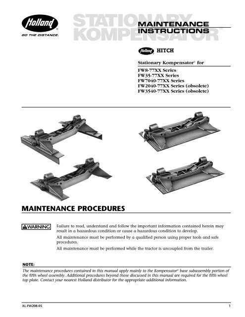
GO THE DISTANCE.<strong>STATIONARY</strong>MAINTENANCE<strong>KOMPENSATOR</strong>®INSTRUCTIONSHITCHStationary Kompensator ® forFW8-77XX SeriesFW35-77XX SeriesFW7040-77XX SeriesFW2040-77XX Series (obsolete)FW3540-77XX Series (obsolete)MAINTENANCE PROCEDURESFailure to read, understand and follow the important information contained herein mayresult in a hazardous condition or cause a hazardous condition to develop.All maintenance must be performed by a qualified person using proper tools and <strong>saf</strong>eprocedures.All maintenance must be performed while the tractor is uncoupled from the trailer.NOTE:The maintenance procedures contained in this manual apply mainly to the Kompensator ® base subassembly portion ofthe fifth wheel assembly. Additional procedures beyond those discussed in this manual are required for the fifth wheeltop plate. Contact your nearest Holland distributor for the appropriate additional information.XL-FW208-05 1
AS-NEEDED LUBRICATION:The following should be performed at installation andthen at least once per week or more frequently asrequired by operating conditions.1. Apply grease to the top bearing surface ofthe shoe (ITEM 2) through the grease fittingson the fifth wheel top plate (see Figure 1, ➊).2. Lift up on the fifth wheel top plate and applygrease to:A. ...the grease fittings ➋ on the side of theshoes (ITEM 3) which fills a reservoir thatrequires approximately 2 pounds of greaseto fill.B. ...the grease fittings ➌ on the base (ends) ofthe cradle (ITEM 14).C. ...the fittings ➍ on the front and back ofthe cradle (ITEM 15).FIGURE 1Greaseresevoir➍Grease frontcradle zerks.➊Grease top plate contactsurfaces. The grease fitting ison the side or under the frontof the top plate.Fill reservoirswith grease,then applygrease to shoesusing zerks.Grease cradle zerks.All of the following must be performed after theinitial 5,000 miles of service and then every 60,000miles or 6 months, whichever comes first.Perform all inspections and adjustment<strong>saf</strong>ter a thorough steam cleaning.NOTE: Severe service applications may requiremore frequent intervals.1. Inspection – GeneralA. Inspect the fifth wheel mounting. Checkbolt torque and replace any loose,missing, or damaged bolts. Check forbroken, distorted, or cracked components.Repair or replace as needed.B. Inspect fifth wheel top plate andKompensator assembly for bent, worn,cracked, or broken parts. Replace withHOLLAND parts only. (See Figure 2.)2. Fifth Wheel Locking Mechanism: MeasureFore-Aft Movement.A. Test the operation of the fifth wheel lockingmechanism using a Holland TF-TLN-5001,2˝ Kingpin or TF-TLN-1500, 3 1 /2˝ KingpinLock Tester. Inspect for proper locking.➌➋FIGURE 2Check for warn,bent, or brokenparts. Replace withHolland parts only.Check bolt torque.Replace missingor damaged bolts.Check forcracked,broken, ordistortedcomponents.Do not use any fifthwheel which does notoperate properlyB. Check the adjustment of the fifth wheellocks by moving the lock tester fore andaft when locked in the locking mechanism.Fore and aft play should be adjusted to lessthan 0.06˝ ( 1 /16˝). Adjust the fifth wheellocks as described in Holland Publications“Fifth Wheel Maintenance Procedures”XL-FW303-XX, XL-FW308-XX, andXL-FW354-XX for the particular type oflocking mechanism. If the locks cannot beproperly adjusted due to wear, the fifthwheel should be repaired or replaced. YourHOLLAND Distributor has parts, part kitsand fifth wheel top plates available.Improper adjustment cancause improper locking ofthe mechanism.C. The trailer kingpin should also beinspected for wear and damage.A HOLLAND Kingpin Gauge (TF-0110)is available to aid this inspection.3. Kompensator Base Sub-Assembly:Measure Fore-Aft Movement.A. Measure the fore and aft movement of theshoe sub-assembly in the Kompensatorbracket. (See Figure 3.)Check fore/aftmovement of shoe.Shim if greaterthan .060".Bearing plateITEM 12, ITEM 13Shim ITEM 11FIGURE 3 FIGURE 42 XL-FW208-05
Add shims (ITEM 11) and/or new bearingplates (ITEM 12 or ITEM 13) when thismovement exceeds 0.060˝ ( 1 /16˝). See Figures3 through 6.FIGURE 5 FIGURE 6BEARINGPLATESHIMB. If shimming is required, shim as follows:1. Remove shoes and disassembleKompensator. See Figure 3.2. Remove bearing plates (ITEM 12 andITEM 13). Measure thickness if less than.31˝ ( 5 /16˝) thick. Replace with newHolland part.3. Install shims.4. Check for free lateral movement of shoein frame. DO NOT over shim.Recheck fore and aft movement of theshoe subassembly. Movement is to be lessthan .06˝ ( 1 /16˝).C. Inspect the cushions (ITEM 5) and othercomponents for distortion and splitting orcracking. If disassembly is required, followsteps 1–5 under section 4 below, and replaceas required.4. Kompensator Base Subassembly: MeasureUpward Movement:A. Measure upward clearance on the assembly.Do this on one side at a time by lifting the fifthwheel top plate upward manually with the aidof a bar (see Figure 7). Clamp the shoe (ITEM 2)on the opposite side to prevent its movement,which will affect the measurement (see Figure7). If the total movement exceeds 0.5˝ ( 1 /2˝),the unit should be disassembled for furtherinspection.FIGURE 8FIGURE 9If disassembly is required, follow thesteps below:1. Remove the fifth wheel top plate fromthe Kompensator base removing theappropriate roll pins and bracketpins or cotter pins, nuts and bolts,depending upon model.2. Remove all loose internal parts (shoes,tie rod, etc.).3. Inspect all parts for distortion, wearand cracking. Replace if necessary.4. Measure the thickness of the curvedbase of the shoe sub-assembly(ITEM 2). The shoe should be replaced ifthe base thickness measures less than0.31˝ ( 5 /16˝). See Figure 8.5. Reassemble and lubricate as notedabove. Check for free lateral andfore-aft movement of the shoesub-assemblies after reassembly.NOTE:For severe dusty/dirty environments, shoedust covers (see Figure 9) are available.request Holland parts XA-0128-Land XA-0128-R.DUST COVERSSHOE BASEMeasure shoe basethickness. Replace ifit is less than .31˝( 5 /16˝).FIGURE 7Pry or lift one side at a time.Disassemble if it exceeds 0.5".XL-FW208-05 3
Parts Breakdown202123 124* or 4A**910115678764* or 4A**14RK-01370 KIT – OPTIONAL1515LOCKOUT PARTS 18 14(BOTH SIDES)91059101113321915 1516171ITEM PART NO. NO. PART NAME ITEM PART NO. NO. PART NAME1 XA-45-77XX 1 Kompensator ® Frame11 XA-0014 2 Shim (as required)2 XA-0024 2 Shoes Subassembly – includes part no. (3) 12 XA-01997 1 Bearing Plate – Right Hand3 XB-H-38-F 2 Grease Fitting13 XA-01998 1 Bearing Plate – Left Hand4* XB-0011 2 Rubber Cushion14 XB-H-38-A 4 90° Grease Fitting4A** XB-0012 2 Rubber Cushion15 XB-H-38 4 Grease Fitting5 XB-0009 2 Cushion16 XA-01429 2 “L” Pin Subassembly6 XA-1284-2 2 Washer17 XA-01427 2 Lockout Stop7 XB-01923 2 Spring18 XB-382 2 Cotter Pin .19˝ x 1.25˝8 XA-39 1 Tie Bar19 XB-847 2 Shackle Pin9 XB-C-59 4 Hex Nut 1 /2˝-1320 XA-0128-L 1 Dust Cover (optional)10 XB-T-45-1 4 Lock Washer 1 /2˝21 XA-0128-R 1 Dust Cover (optional)* Bushings used in conjunction with FW8, FW35, FW2040, FW3540 or FW3640 series fifth wheels.** Bushings used in conjunction with FW7040 series fifth wheels.GO THE DISTANCE.HOLLAND USA, INC.1950 Industrial Blvd. • P.O. Box 425 • Muskegon, MI 49443-0425Phone 888-396-6501 • Fax 800-356-3929www.the<strong>holland</strong>groupinc.comCopyright © April 2002 • The Holland Group, Inc.Holland USA, Inc. Facilities:Denmark, SC Muskegon, MIDumas, AR Warrenton, MOHolland, MI Whitehouse Station, NJMilpitas, CA Wylie, TXHolland International, Inc.Holland, MIPhone: 616-396-6501Fax: 616-396-1511Holland Hitch of Canada, Ltd.Woodstock, Ontario • CanadaPhone: 519-537-3494Fax: 800-565-7753Holland Equipment, Ltd.Norwich, Ontario • CanadaPhone: 519-863-3414Fax: 519-863-2398Holland Hitch Western, Ltd.Surrey, British Columbia • CanadaPhone: 604-574-7491Fax: 604-574-0244Ph: 888-396-6501 Fax: 800-356-39294 XL-FW208-05