tachoISSUE3 en - Triumph Instructions.com
tachoISSUE3 en - Triumph Instructions.com
tachoISSUE3 en - Triumph Instructions.com

You also want an ePaper? Increase the reach of your titles
YUMPU automatically turns print PDFs into web optimized ePapers that Google loves.
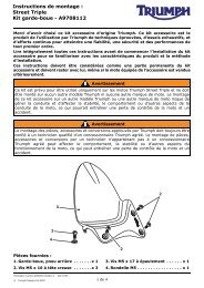
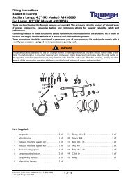
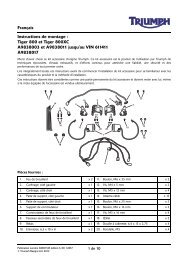
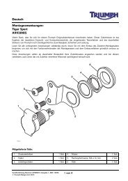
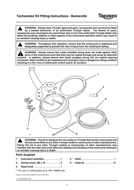
Tachometer Kit Fitting <strong>Instructions</strong> - BonnevilleWARNING: Always have <strong>Triumph</strong> approved parts, accessories and conversions fittedby a trained technician of an authorised <strong>Triumph</strong> dealer. The fitm<strong>en</strong>t of parts,accessories and conversions by a technician who is not of an authorised <strong>Triumph</strong> dealer mayaffect the handling, stability or other aspects of the motorcycle operation which may result inan accid<strong>en</strong>t causing injury or death.WARNING: Throughout this operation, <strong>en</strong>sure that the motorcycle is stabilised andadequately supported to prev<strong>en</strong>t the risk of injury from the motorcycle falling.WARNING: Always <strong>en</strong>sure that newly installed wiring does not chafe against otherparts of the motorcycle such that they may be rubbed through and cause an electricalproblem. In addition, always <strong>en</strong>sure that newly installed wiring will not restrict steeringmovem<strong>en</strong>t. Both conditions are hazardous and could give rise to a dangerous riding conditionresulting in a fire, loss of motorcycle control and/or an accid<strong>en</strong>t.134*2WARNING: This kit is designed for use solely on <strong>Triumph</strong> Bonneville motorcycles andshould not be fitted to any other <strong>Triumph</strong> model or motorcycles of other manufacturers.Fitting this kit to any other <strong>Triumph</strong> models or motorcycles of other manufacturers mayinterfere with the rider and could affect the stability and handling of the motorcycle leading toan accid<strong>en</strong>t causing injury or death.Parts Supplied1. Instrum<strong>en</strong>t assembly .............. 12. Domed screw, M6 x 16 ............ 43. Reset knob ....................... 1* For use on motorcycles up to VIN 149948 only.<strong>Instructions</strong> part number A9900173 issue 2 ADC 82135*4.* Cable ............................ 15.* Cable tie ........................ 15E <strong>Triumph</strong> Designs 20021
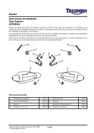
Tachometer Kit Fitting <strong>Instructions</strong> - Bonneville1. Undo the two screws located under the rear ofthe seat and remove the seat.2. Disconnect the battery, disconnecting th<strong>en</strong>egative (-) lead first.3. Undo the screws and free the headlight rimfrom the shell.7. Disconnect the breather hose from theright-hand side of the tank.NOTE: On California models, thishose is the evaporative loss systemhose. Plug the hose <strong>en</strong>d whilst it isdisconnected.8. Remove the fuel tank, taking care not to losethe mounting rubbers.9. Insert one <strong>en</strong>d of the cable supplied with thekit into the igniter connection block as shownbelow.12T90804811. Headlight rim screw4. Disconnect the wiring connectors from theheadlight bulb and sidelight bulb and removethe headlight.Motorcycles up to VIN 149948 only5. Turn the fuel tap OFF and disconnect the hosefrom the tapWARNING: Observe the warningadvice giv<strong>en</strong> in the service manualon the safe handling of fuel and fuelcontainers.A fire, causing personal injury and damageto property could result from spilled fuel orfuel not handled or stored correctly.11. Cable2. Igniter connection block10. Route the cable from the igniter to the back ofthe headlamp shell as shown. Secure thecable to the main harness and frame at regularintervals using the cable ties supplied with thekit.6. Slack<strong>en</strong> and remove the fuel tank mountingbolts.1T908.APS.021. Fuel tank mounting bolts2
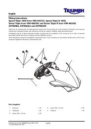
Tachometer Kit Fitting <strong>Instructions</strong> - Bonneville11. Feed the cable through the back of theheadlamp shell. Locate the main harnessinstrum<strong>en</strong>t connector block. Insert the free<strong>en</strong>d of the cable into the top row of theconnector block 3rd from the left as shown.14. Unscrew the retaining ring and detach thecable from the speedometer.1 21T908.16.101. Speedometer cable retaining ring1. Cable2. Instrum<strong>en</strong>t connector blockAll VINs12. Disconnect the instrum<strong>en</strong>t connector block.13. Unscrew the mounting bolts and free thespeedometer assembly from the top yoke.NOTE: The fixings will not be refitted butshould be retained for future re•use if thetachometer kit is ever removed.15. Note the instrum<strong>en</strong>t assembly sub•harnessrouting for future refer<strong>en</strong>ce. Withdraw theinstrum<strong>en</strong>t connector from the back of theheadlamp connector. Remove the <strong>com</strong>pletespeedometer assembly from the motorcycle.16. Undo the retaining screw and remove the tripmeter reset knob. The retaining screw will bere•used.NOTE: The trip meter reset knob will notbe refitted but should be retained forfuture re•use if the tachometer kit is everremoved.111T908.A1.011. Speedometer assembly mounting bolts1. Trip meter reset knob3
Tachometer Kit Fitting <strong>Instructions</strong> - Bonneville17. Unscrew the speedometer cover nuts. Collectthe two washers and remove the cover fromthe base of the speedometer.19. Lift the speedometer out from thespeedometer housing. Remove the mountingrubber from the housing.121T908.16.161. Speedometer cover nuts18. Collect two further washers from the threadedposts. Free the bulbholders from thespeedometer as shown below.T908.16.341. Speedometer housing2. Mounting rubber20. Undo the screws and remove the cover fromthe base of the housing to gain access to thebulbholders.31T908.16.171. Threaded post2. Washer3. Bulbholder23T908.16.111. Bulbholder cover21. Push each bulbholder forwards through thehousing.1T908.16.121. Bulbholder4
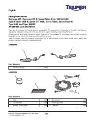
Tachometer Kit Fitting <strong>Instructions</strong> - Bonneville27. Position the bulbholder cover to theinstrum<strong>en</strong>t assembly as shown. Refit thescrews and secure the cover to the instrum<strong>en</strong>tassembly.129. Install the speedometer into the instrum<strong>en</strong>tassembly and fit the bulbholders. Fit a washeronto each threaded post. Seat the cover onthe speedometer. Refit the nuts and washersand tight<strong>en</strong> securely.231. Screw2. Bulbholder cover3. Instrum<strong>en</strong>t assembly28. Fit the original mounting rubber to the newinstrum<strong>en</strong>t assembly as shown below.Ensure that the mounting rubber tab <strong>en</strong>gagesin the slot.1. Speedometer2. Bulbholder3. Washer4. Threaded post5. Speedometer cover6. Nut6 3 5 3 4 212330. Fit the trip meter reset knob supplied with thekit to the speedometer. Ensure that the flatsurface inside the trip knob <strong>en</strong>gages with theflat on the trip meter reset spindle. Secureusing the original retaining screw.11. Mounting rubber2. Tab3. Slot2131. Trip meter reset knob2. Trip meter reset spindle3. Retaining screw6
Tachometer Kit Fitting <strong>Instructions</strong> - Bonneville31. Route the instrum<strong>en</strong>t assembly sub•harnessas noted in step 15. Feed the instrum<strong>en</strong>tassembly connector through the back of theheadlamp shell and connect to the mainharness.32. Reconnect the speedometer cable.33. Attach the instrum<strong>en</strong>t assembly to the topyoke as shown below using the four M6 x 16domed screws supplied with the kit. Tight<strong>en</strong>the bolts to 9Nm.1136. Ensure the collars and rear mounting rubbersare correctly fitted th<strong>en</strong> install the fuel tankmounting bolts, tight<strong>en</strong>ing them to 9Nm.37. Turn the fuel tap ON and check for fuel leaks.All VINs38. Reconnect the wiring connectors to theheadlight and sidelight bulbs.39. Seat the headlight rim correctly in its shell andsecurely tight<strong>en</strong> its screws.40. Reconnect the battery, connecting thepositive (+) terminal first.41. Check for correct operation of the headlamp.42. Check for correct operation of all tell•talelights and instrum<strong>en</strong>t illumination.43. Check for correct operation of all other lightingand light signalling devices.44. Install the seat, tight<strong>en</strong>ing its screws to10 Nm.1. Domed screwMotorcycles up to VIN 149948 only34. Ensure the fuel tank front mounting rubbersare correctly fitted to the frame th<strong>en</strong> refit thetank.1T908.APS.071. Fuel tank front mounting rubbers35. Securely reconnect the fuel hose andbreather hose to the tank. On Californiamodels connect the evaporative loss systemhose.7