Hanging Platform - Combisafe
Hanging Platform - Combisafe
Hanging Platform - Combisafe

You also want an ePaper? Increase the reach of your titles
YUMPU automatically turns print PDFs into web optimized ePapers that Google loves.
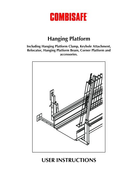
®COMBISAFE<strong>Hanging</strong> <strong>Platform</strong>Including <strong>Hanging</strong> <strong>Platform</strong> Clamp, Keyhole Attachment,Relocator, <strong>Hanging</strong> <strong>Platform</strong> Beam, Corner <strong>Platform</strong> andaccessories.USER INSTRUCTIONS
<strong>Combisafe</strong> <strong>Hanging</strong> <strong>Platform</strong>ContentsMAINTENANCE ....................................................................................................... 47Safety checks ..................................................................................................... 47Reconditioning .................................................................................................. 47Scrapping .......................................................................................................... 48Storage .............................................................................................................. 48© <strong>Combisafe</strong> International AB - UI 2100-EN-1040Subject to changes.3
General<strong>Combisafe</strong> <strong>Hanging</strong> <strong>Platform</strong>GeneralThe <strong>Combisafe</strong> <strong>Hanging</strong> <strong>Platform</strong> is used, for example, for roof work, finishingwork or lighter work where a platform or scaffolding is required.A <strong>Hanging</strong> <strong>Platform</strong> is often cheaper to install than traditional scaffolding. In addition,it does not take up any ground space, and there is no risks of burglary viathe scaffolding.The system is based on Consoles where Steel Boardwalks or scaffold planks arelaid to create a working area. The Consoles can be fitted in different ways usingthe various attachments.These attachments provide a range of assembly options: the <strong>Hanging</strong> <strong>Platform</strong> canbe used for many different applications and for many different types of job.You can adjust the attachments in the <strong>Hanging</strong> <strong>Platform</strong> Console, which also providethe option of adjusting the height of the working surface of the <strong>Hanging</strong> <strong>Platform</strong>.The <strong>Hanging</strong> <strong>Platform</strong> has been type approved in accordance with AFS 1990:12and SS-EN12811-1 from SP Swedish Testing and Research Institute, Type test certificateNo 270303Type test certificate No 270303.4
<strong>Combisafe</strong> <strong>Hanging</strong> <strong>Platform</strong>Safety instructionsSafety instructionsAlways check products and equipment before useCheck all component parts to the <strong>Hanging</strong> <strong>Platform</strong> system before assembly.Never use damaged or rusty materials as this can affect safety.Do not combine productsIt is not recommended to install, combine or interconnect <strong>Hanging</strong> <strong>Platform</strong>susing products other than those supplied by <strong>Combisafe</strong>. <strong>Combisafe</strong> product liabilityonly applies to combinations with correctly fitted <strong>Combisafe</strong> products.Always use personal fall arrest equipmentPersonal fall arrest equipment must always be worn during assembly anddismantling when a risk of falling exists. This also applies to work carried out froma MEWP (mobile elevating working platform).1974_600Figure 1. Personal fall arrest equipmentInspection after a fallIf a guard rail is subject to an accident or exposed to a heavy load, the rail mustbe checked by a competent person. Contact <strong>Combisafe</strong> in the event of uncertainty.5
Safety instructions<strong>Combisafe</strong> <strong>Hanging</strong> <strong>Platform</strong>Wind, ice and snowThe <strong>Hanging</strong> <strong>Platform</strong> is designed to withstand a wind load of 770 N/m² (equal toa wind speed of around 35 m/s) and a wind load of 200 N/m² under working conditions(equal to a wind speed of around 18 m/s).Should you increase the density of the guard rail, for example, by using scaffoldsheeting or plywood, the wind load at the given wind strength will increase. Nevercover the guard rail without checking that the permitted wind load has not beenexceeded.The <strong>Hanging</strong> <strong>Platform</strong> is not designed for exposure to static or dynamic loads resultingfrom ice and snow. Always keep the <strong>Hanging</strong> <strong>Platform</strong> free from ice andsnow.Remember• Plan the fall guard at an early stage, this will benefit everyone.• Only use inspected safety products.• Ensure sound and safe access to the installation site/work site and to the<strong>Hanging</strong> <strong>Platform</strong>. Remember not to jump down onto the <strong>Platform</strong>.• Cordon off below and around the assembly area in connection with the installationso that unauthorized personnel are not injured if, for example, youshould drop tools or material.• Use tools designed for the type of work to be carried out.• Tighten screws properly and check that split pins lock correctly.• Keep threads clean and lubricated.• Keep the installation area in order.• A safe workplace is an agreeable workplace.• Many fall accidents occur from a low height.• Ensure that the height of the guard rail above the eaves is sufficient.• Check the pitch of the roof if the <strong>Hanging</strong> <strong>Platform</strong> is used as fall guard forroofs (see EN13374).• Check the marking with information on installed system.6
Technical data<strong>Combisafe</strong> <strong>Hanging</strong> <strong>Platform</strong>2100 <strong>Hanging</strong> <strong>Platform</strong> ConsoleTechnical data153426Figure 2. <strong>Hanging</strong> <strong>Platform</strong> ConsoleItem Quantity Part no. Description Weight:1 1 10021 <strong>Hanging</strong> <strong>Platform</strong> Console Body 13 kg2 1 100043 Wood insert, bottom 1.0 kg3 2 100044 Wood insert, side 0.5 kg4 3 100062 Wood screw ST 5.5x32 -5 1 1900 Lock Pin 0,1 kg6 1 100165 Shaft Locking Pin -Weight: 15 kgSurface finish: Hot-dip galvanizedThe <strong>Hanging</strong> <strong>Platform</strong> Console is the foundation of the <strong>Hanging</strong> <strong>Platform</strong> system,it is the load bearing part where the walking surface and the rail are anchored. Itcan be installed in different ways.8
<strong>Combisafe</strong> <strong>Hanging</strong> <strong>Platform</strong>Technical data2130 <strong>Hanging</strong> <strong>Platform</strong> ClampFigure 3. <strong>Hanging</strong> <strong>Platform</strong> ClampItem Quantity Part no. Description Weight:1 1 10329 <strong>Hanging</strong> <strong>Platform</strong> Clamp Body 4.3 kg2 1 10025 Clamp screw for <strong>Hanging</strong> <strong>Platform</strong> 0.6 kgClamp3 1 10013 Clamp cap 0.07 kg4 1 100033 Screw M12-200 0.2 kg5 1 100004 Starlock washer -Weight: 5 kgSurface finish: Hot-dip galvanized / ElectrogalvanizedThe <strong>Hanging</strong> <strong>Platform</strong> Clamp is used to install the <strong>Hanging</strong> <strong>Platform</strong> to the rooftruss heads.9
Technical data<strong>Combisafe</strong> <strong>Hanging</strong> <strong>Platform</strong>2150 Keyhole AttachmentWeight: 3.6 kgSurface finish: Hot-dip galvanizedFigure 4. Keyhole AttachmentThe Keyhole Attachment is used when you want to install the <strong>Hanging</strong> <strong>Platform</strong>with a screw assembly, e,g. to a wall.10
<strong>Combisafe</strong> <strong>Hanging</strong> <strong>Platform</strong>Technical data2140 Relocator40010533Weight: 3.9 kgSurface finish: Hot-dip galvanizedFigure 5. RelocatorThe Relocator is used when you want to extend the area of the <strong>Hanging</strong> <strong>Platform</strong>.NOTEOnly use the Relocator together with the Keyhole Attachment and doubleShaft Locking Pins in the Telescope Arm.11
Technical data<strong>Combisafe</strong> <strong>Hanging</strong> <strong>Platform</strong>2170 <strong>Hanging</strong> <strong>Platform</strong> BeamFigure 6. <strong>Hanging</strong> <strong>Platform</strong> BeamItem Quantity Part no. Description Weight:1 1 100041 Nut M16 -Weight: 8.6 kgSurface finish: Hot-dip galvanizedThe <strong>Hanging</strong> <strong>Platform</strong> Beam is used when you want to install the <strong>Hanging</strong> <strong>Platform</strong>extending from an edge. The cantilever can be adjusted as necessary.12
<strong>Combisafe</strong> <strong>Hanging</strong> <strong>Platform</strong>Technical dataFigure 7. <strong>Hanging</strong> <strong>Platform</strong> Beam, dimensions and loadsX [mm] Y [mm] F1 [kN] F2 [kN]770 200 2.2 8.5670 300 3.5 9.8570 400 5.2 11.5470 500 7.6 13.9370 600 11.4 17.7F1 are the forces that act on the attachment in the concrete. This consists of twoexpanders with a c-c distance of 100 mm.13
Technical data<strong>Combisafe</strong> <strong>Hanging</strong> <strong>Platform</strong>2300 Steel BoardwalkWeight: 26 kgSurface finish: Hot-dip galvanizedFigure 8. Steel BoardwalkThe Steel Boardwalks are the actual walking surface in the system. They havemany advantages over scaffold planks, but scaffold planks can still be used for thewalking surface.2305 End Toe Board2350_001Figure 9. End Toe BoardWeight: 1 kgSurface finish: Hot-dip galvanized/painted redThe End Toe Board is used at the ends of the Steel Boardwalk.14
<strong>Combisafe</strong> <strong>Hanging</strong> <strong>Platform</strong>Technical data1750/1751 Telescope Arm1120110 6x100120110 10x1008551200Figure 10. Telescope ArmItem Quantity Part no. Description Weight:1 1 100165 Shaft Locking Pin -When using the Relocator, use two Shaft Locking Pins.Weight: 1750 - 2.3 kg, 1751 - 3.0 kgSurface finish: Hot-dip galvanizedThe Telescope Arm represents the support to the facade for the <strong>Hanging</strong> <strong>Platform</strong>system.15
2110_0012110_002Technical data<strong>Combisafe</strong> <strong>Hanging</strong> <strong>Platform</strong>2110 Corner <strong>Platform</strong> Console2 3111201468241Figure 11. Corner <strong>Platform</strong> ConsoleItem Quantity Part no. Description Weight:1 1 100229 Scantling 2.4 kg2 2 100228 Screw -3 2 100027 Nut -Weight: 21 kgSurface finish: Hot-dip galvanizedThe Corner <strong>Platform</strong> is wider than the <strong>Hanging</strong> <strong>Platform</strong> and is used in the corners.16
2115_0022115_001<strong>Combisafe</strong> <strong>Hanging</strong> <strong>Platform</strong>Technical data2115 Corner <strong>Platform</strong> Attachment5002303204103404405402115_003640Figure 12. Corner <strong>Platform</strong> AttachmentWeight: 7.6 kgSurface finish: Hot-dip galvanizedThe Corner <strong>Platform</strong> Attachment is fixed to the corner of the facade.17
2120_0022120_001Technical data<strong>Combisafe</strong> <strong>Hanging</strong> <strong>Platform</strong>2120 Corner Telescope Arm6975974973972971979712010090°Figure 13. Corner Telescope ArmWeight: 2.7 kgSurface finish: Hot-dip galvanizedThe corner Telescope Arm is adapted to support against a corner.18
<strong>Combisafe</strong> <strong>Hanging</strong> <strong>Platform</strong>Technical data2135 Extension BarWeight: 2.4 kgFigure 14. <strong>Hanging</strong> <strong>Platform</strong> Clamp with Extension BarSurface finish: Hot-dip galvanized / ElectrogalvanizedThe Extension Bar is used together with the <strong>Hanging</strong> <strong>Platform</strong> Clamp to install the<strong>Hanging</strong> <strong>Platform</strong> to the corner roof truss.19
1974_501cTechnical data<strong>Combisafe</strong> <strong>Hanging</strong> <strong>Platform</strong>1102 Safety PostArt. 100000Art. 1132Figure 15. Safety PostWeight: 3.5 kgSurface finish: Duplex - Hot-dip galvanizedThe Safety Post is the load bearer for the guard rail.20
<strong>Combisafe</strong> <strong>Hanging</strong> <strong>Platform</strong>Technical data2000 Safety PostFigure 16. Safety PostWeight: 3.6 kgSurface finish: Duplex - Hot-dip galvanizedThe Safety Post is the load bearer for the guard rail.21
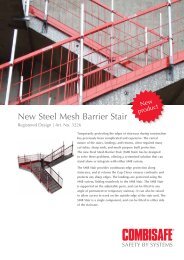
Technical data<strong>Combisafe</strong> <strong>Hanging</strong> <strong>Platform</strong>3203 Steel Mesh BarrierWeight: 19.5 kgFigure 17. Steel Mesh BarrierSurface finish: Phosphatized and powder coated in red.The Steel Mesh Barrier 3203 complies to the requirements in EN 13374 for classesA, B and C.22
<strong>Combisafe</strong> <strong>Hanging</strong> <strong>Platform</strong>Technical data3204 Steel Mesh Barrier 1,3 mWeight: 10.5 kgFigure 18. Steel Mesh Barrier 1,3mSurface finish: Phosphatized and powder coated in red.The Steel Mesh Barrier 3204 complies to the requirements in EN 13374 for classesA, B and C.23
910Max705Technical data<strong>Combisafe</strong> <strong>Hanging</strong> <strong>Platform</strong>2201 Gable Gate55710123456Figure 19. Gable GateItem Quantity Part no. Description Weight:1 1 10564 Gate section 7.6 kg2 2 10063 Screw 0.15 kg3 1 10104 Post 2.9 kg4 1 10103 Variable bracket 1.3 kg5 1 10101 Locking ring 0.04 kg6 1 100051 Tapping flange screw M5-16 -Weight: 11.8 kgSurface finish: Electrogalvanized/painted redThe Gable Gate is used as a rail at the end of the platform.24
918<strong>Combisafe</strong> <strong>Hanging</strong> <strong>Platform</strong>Technical data2220 Gable Gate Extension126403Figure 20. Gable Gate ExtensionItem Quantity Part no. Description Weight:1 1 10601 J-bracket 0.2 kg2 1 100233 Eye bolt 0.07 kg3 1 10602 Gate section 6.5 kgWeight: 6.8 kgSurface finish: Hot-dip galvanizedThe Gable Gate Extension can used to extend Gable Gate 2201.25
Technical data<strong>Combisafe</strong> <strong>Hanging</strong> <strong>Platform</strong>3228 SMB Angle Console500500Figure 21. SMB Angle ConsoleWeight: 3.0 kgSurface finish: Hot-dip galvanizedThe SMB Angle Console is used to connect Steel Mesh Barriers and create a cornerin the end of a <strong>Hanging</strong> <strong>Platform</strong> as an alternative to using the Gable Gate.26
2130_001<strong>Combisafe</strong> <strong>Hanging</strong> <strong>Platform</strong>AssemblyAssembly<strong>Hanging</strong> <strong>Platform</strong> ClampMax c-c distance is 2.4 m.Take into consideration the loads from the <strong>Hanging</strong> <strong>Platform</strong> that affect the rooftrusses and the facade.Check that the A dimension in the table is not exceeded. The A dimension is thedistance from the <strong>Hanging</strong> <strong>Platform</strong> Clamp's attachment point and the roof trussesoutermost support (wall plate).AFigure 22. <strong>Hanging</strong> <strong>Platform</strong> ClampRoof truss dimension inmmA dimension in mmStrength classK12 K18 K24 K3045x95 62 93 117 13745x120 99 148 186 21945x145 144 216 272 32045x170 198 297 374 44045x195 260 390 492 57845x220 331 497 626 736The table refers to new construction and is calculated based on BKR94 in safetyclass 227
Assembly<strong>Combisafe</strong> <strong>Hanging</strong> <strong>Platform</strong>Check that the roof truss is free from cracks and knots or other defects that mightaffect strength.1. Drill a 13 mm hole in the roof truss end as per the picture below. The dimensionsrefer to the distance from the hole to the edge of the roof truss. In thedirection of the grain this must be at least 120 mm, and the distance at rightangles to the grain must be at least 60 mm.4060120=602100_018[mm]Ø 1345-150Figure 23. Dimensional draft2. Place the <strong>Hanging</strong> <strong>Platform</strong> Clamp over the hole. The <strong>Hanging</strong> <strong>Platform</strong>Clamp can be placed in two different directions depending on which side ofthe roof truss you want to suspend the <strong>Hanging</strong> <strong>Platform</strong> Console, as well aswhere the support to the facade ends up.3. Attach the <strong>Hanging</strong> <strong>Platform</strong> Clamp using the M12x200 screw through thehole. Thread the M12 screw in the clamp screw's internal thread to the bottom.Check that the <strong>Hanging</strong> <strong>Platform</strong> Clamp is hanging plumb and tightensecurely.Figure 24. Placement of <strong>Hanging</strong> <strong>Platform</strong> Clamp28
<strong>Combisafe</strong> <strong>Hanging</strong> <strong>Platform</strong>AssemblyKeyhole AttachmentMax c-c distance is 2.4 m.Take into consideration the loads from the <strong>Hanging</strong> <strong>Platform</strong> that affect the attachmentand the facade.1. Fit the Keyhole Attachment in the form of expander, and through thread supportor equivalent. See instructions from the expander manufacturer or equivalent.2. Fit the Keyhole Attachment on to the stud. The Keyhole Attachment is sizedto accept an M16 fixing.3. Check that the Keyhole Attachment is hanging plumb and tighten securely.Figure 25. Assembly of Keyhole Attachment29
Assembly<strong>Combisafe</strong> <strong>Hanging</strong> <strong>Platform</strong>Alternative assembly of Keyhole AttachmentAs an alternative the <strong>Hanging</strong> <strong>Platform</strong> Console, Telescope Arm and Keyhole Attachmentcan be fitted together before being suspended.Figure 26. Alternative assembly of Keyhole Attachment30
<strong>Combisafe</strong> <strong>Hanging</strong> <strong>Platform</strong>Assembly<strong>Hanging</strong> <strong>Platform</strong> BeamMax c-c distance is 2.4 m.1. Decide how much of the <strong>Hanging</strong> <strong>Platform</strong> Beam needs to protrude. Takeinto consideration the loads from the <strong>Hanging</strong> <strong>Platform</strong> Beam when selectingthe fixings and ensure the capacity of the support edge. These loads affectthe length of cantilever.2. Fit the <strong>Hanging</strong> <strong>Platform</strong> Beam using suitable fixings.Figure 27. Assembly of <strong>Hanging</strong> <strong>Platform</strong> Beam3. Fit the Keyhole Attachment on the <strong>Hanging</strong> <strong>Platform</strong> Beam screw.4. Check that the Keyhole Attachment is hanging plumb and tighten the screw.Figure 28. Assembly of Keyhole Attachment on <strong>Hanging</strong> <strong>Platform</strong> Beam31
Assembly<strong>Combisafe</strong> <strong>Hanging</strong> <strong>Platform</strong>RelocatorNOTEOnly use the Relocator together with the Keyhole Attachment.Max c-c distance is 2.4 m.Take into consideration the increased fixing load when using the Relocator, andensure the suitability of both fixing and base material.1. Assembly of Relocator on Keyhole Attachment.2. Fit the Keyhole Attachment as per the assembly of Keyhole Attachment instructions.Page 29.3. Fix the Relocator on the Keyhole Attachment using a Lock Pin.Figure 29. Assembly of Relocator32
<strong>Combisafe</strong> <strong>Hanging</strong> <strong>Platform</strong>AssemblyAlternative assembly of RelocatorFit the Relocator on the Keyhole Attachment before mounting on the facade.Figure 30. Alternative assembly of Relocator33
Assembly<strong>Combisafe</strong> <strong>Hanging</strong> <strong>Platform</strong><strong>Hanging</strong> <strong>Platform</strong> Console and Telescope Arm1. Check that the facade can accept the load applied through the TelescopeArm. The force applied by the Telescope Arm is equivalent to the pull outload applied to the fixing.2. Fit the Telescope Arm into the <strong>Hanging</strong> <strong>Platform</strong> Console. Select the appropriateTelescope Arm and adjust it to set the <strong>Hanging</strong> <strong>Platform</strong> Console level.The simplest way of doing this is to test a <strong>Hanging</strong> <strong>Platform</strong> Console with aTelescope Arm and adjust the Telescope Arm to the correct dimensions.3. Secure the Telescope Arm with Shaft Locking Pin.Figure 31. Telescope Arm34
<strong>Combisafe</strong> <strong>Hanging</strong> <strong>Platform</strong>AssemblyNOTEIf a Relocator is used, the Telescope Arm is attached using two Shaft LockingPins.Figure 32. Anchoring of Telescope Arm4. Fit the <strong>Hanging</strong> <strong>Platform</strong> Console at a suitable height on the attachment. Fixthe <strong>Hanging</strong> <strong>Platform</strong> Console using the Lock Pin.Figure 33. Fixing the Telescope Arm5. Check that the Telescope Arm provides proper support from the facade.35
2115_004Assembly<strong>Combisafe</strong> <strong>Hanging</strong> <strong>Platform</strong>Assembly of Corner <strong>Platform</strong>The Corner <strong>Platform</strong> can be assembled in two ways: using a Corner <strong>Platform</strong> Attachmentor extended <strong>Hanging</strong> <strong>Platform</strong> Clamp.Assembly with Corner <strong>Platform</strong> Attachment1. Fit the Corner <strong>Platform</strong> Attachment using a suitable fixing on each side of thecorner. Each anchor must be capable of accepting a combined load of5.0 kN in withdrawal load and 6.3 kN in shear. With some fixings it may bepossible to drill straight through the Corner <strong>Platform</strong> Attachment, using it asa drill guide. Now continue to assemble the Corner <strong>Platform</strong> as per item 2Page 37.Figure 34. Assembly of Corner <strong>Platform</strong> AttachmentAssembly with extended <strong>Hanging</strong> <strong>Platform</strong> ClampThis assumes that the roof truss protrudes at a 45° angle in the corner. Check thebearing capacity of the roof truss.1. Fit an extended <strong>Hanging</strong> <strong>Platform</strong> Clamp to the corner roof truss, see assemblyof <strong>Hanging</strong> <strong>Platform</strong> Clamp. Page 27. Now continue to assemble the Corner<strong>Platform</strong> as per item 2 Page 37.36
<strong>Combisafe</strong> <strong>Hanging</strong> <strong>Platform</strong>Assembly2. Fit the Corner Telescope Arm in the Corner <strong>Platform</strong> and adjust the length.This can be adjusted later on site, but it helps if the length is right from thebeginning.Figure 35. Assembly of Corner Telescope Arm on Corner <strong>Platform</strong>37
Assembly<strong>Combisafe</strong> <strong>Hanging</strong> <strong>Platform</strong>3. Fit the Corner <strong>Platform</strong> on the Corner Attachment or Clamp. Lock the Corner<strong>Platform</strong> using a Lock Pin at the same height as nearby <strong>Hanging</strong> <strong>Platform</strong>s.Figure 36. Assembly of Corner <strong>Platform</strong> on Corner Attachment or Clamp.4. Fit the Steel Boardwalks or scaffold planks as walking surface.Figure 37. Assembly of Steel Boardwalk on Corner <strong>Platform</strong>38
<strong>Combisafe</strong> <strong>Hanging</strong> <strong>Platform</strong>Assembly5. If Steel Boardwalks are used, these must be cut to suit the Corner <strong>Platform</strong>.The toe board is cut for each Steel Boardwalk on one side so that the sectionscan lie staggered. The two Steel Boardwalks must be cut handed to ensureyou get a left and a right Boardwalk.Figure 38. Placement and cutting of Steel BoardwalksInner cornerThe Corner <strong>Platform</strong> can also be used as an inner corner uassuming that an attachmentcan be fitted.In order for a Corner Telescope Arm to give support in an inner corner, you haveto insert a wooden block in it. Either drill a hole in the bent steel section in thecorner Telescope Arm enabling you to nail or screw a wooden block to it, or fitthe wooden block in the corner of the building so that the Corner Telescope Armgets support from it.Figure 39. Wooden block and Corner Telescope Arm39
Assembly<strong>Combisafe</strong> <strong>Hanging</strong> <strong>Platform</strong>Steel Boardwalk1. Assemble the Steel Boardwalks in the <strong>Hanging</strong> <strong>Platform</strong> Consoles.2. Fix the Steel Boardwalks using screws in the <strong>Hanging</strong> <strong>Platform</strong> Consoles'wood inserts.Figure 40. Fixing the Steel Boardwalks3. Overlap the Steel Boardwalks on the <strong>Hanging</strong> <strong>Platform</strong> Consoles. The minimumoverlap over the <strong>Hanging</strong> <strong>Platform</strong> Console is 100 mm. The maximumfree protrusion in the end is 200 mm.Min 100 mmMin 100 mmMax 2,4 mMax 200 mm2100_030Figure 41. Steel Boardwalk protrusion40
<strong>Combisafe</strong> <strong>Hanging</strong> <strong>Platform</strong>AssemblyScaffold planks and toe boardScaffold planks can be used instead of Steel Boardwalks.Scaffold planks must be 45 mm thick and have a minimum of strength class K24.1. Fit three scaffold planks across the width and anchor these using nails orscrews in the wood inserts of the <strong>Hanging</strong> Support Console.Figure 42. Assembly of scaffold planks2. The scaffold plank is joined by staggering them on the Consoles. Where possibleuse a wedge at overlaps to avoid the risk of stumbling. The minimumoverlap over the Console is 100 mm. The maximum free protrusion in theend is 200 mm. Where possible, secure the boards together to aviod a singleboard deflection.41
Assembly<strong>Combisafe</strong> <strong>Hanging</strong> <strong>Platform</strong>3. Attach the toe boards to the walking area by nailing or screwing these to the<strong>Hanging</strong> <strong>Platform</strong> Console's upright wood inserts.Figure 43. Assembly of toe boardsSafety Post and Steel Mesh Barrier 32031. Fit the Safety Posts into the attachments on the <strong>Hanging</strong> <strong>Platform</strong> Consoles,with the brackets facing inwards.2. Press in Quiclox and press the Safety Post down into the attachment. The SafetyPost is locked when Quiclox snaps out in the hole in the attachment.42
<strong>Combisafe</strong> <strong>Hanging</strong> <strong>Platform</strong>AssemblyFigure 44. Assembly of Safety Post43
RRAssembly<strong>Combisafe</strong> <strong>Hanging</strong> <strong>Platform</strong>3. Fit the Steel Mesh Barriers onto the Safety Posts by suspending them over theSafety Posts and brackets. Both brackets on the Safety Post must go throughthe mesh: the top of the Safety Post must go up through the top edge of theSteel Mesh Barriers.2100_035Figure 45. Assembly of the Steel Mesh Barrier44
2350_002<strong>Combisafe</strong> <strong>Hanging</strong> <strong>Platform</strong>AssemblyEnd Toe BoardAttach the End Toe Board onto the Steel Boardwalks using four screws. We recommendfitting the end sections onto the Steel Boardwalks on the ground beforelifting into position.Figure 46. Assembly of End Toe BoardsGable GateOne of two methods of enclosing also the ends of the hanging <strong>Platform</strong> is using aGable Gate.In order to fit the Gable Gate to the end of the platform, a guide is needed. This isformed by fitting two pieces of wood 45x95 mm into the last two Safety Posts. Fitthe wooden guides into the post brackets outside of the Steel Mesh Barriers. Letthe wooden rails protrude around 150 mm beyond the edge of the Steel Mesh Barrier.Attach the guides to the Safety Posts using nails or screws. Fit the Gable Gateonto the wooden guides by placing the Gable Gate's channeled sections over theguides and tightening the attachment screws on the channeled sections. If necessarythe Gable Gate 2201 can be combined with a Gable Gate Extension 2220.45
Assembly<strong>Combisafe</strong> <strong>Hanging</strong> <strong>Platform</strong>Steel Mesh Barrier 3204Another method of closing the end of the platform and make sure the working areais fully screened is using a Steel Mesh Barrier 3204 combined with SMB AngleConsoles 3228 to interconnect the Steel Mesh Barriers.Mount the two SMB Angle Consoles 3228 to the longitudinal Steel Mesh Barrier3203 first and make sure they are positioned close to the bottom and top of theBarrier, as far apart as possible. Put the shorter Steel Mesh Barrier 3204 into positionperpendicularly and secure it to the two SMB Angle Consoles.Figure 47. Closing end of platform by using Steel Mesh Barrier 3204 and SMBAngle Consoles 322846
<strong>Combisafe</strong> <strong>Hanging</strong> <strong>Platform</strong>InspectionInspectionInspection after assemblyThe completed installation must be inspected prior to handover.The following checklist should be used:Checklist for installing the <strong>Hanging</strong> <strong>Platform</strong>• Has the <strong>Hanging</strong> <strong>Platform</strong> been inspected and does it conform to the localregulations?• Is the max c-c distance 2.4 m?• Are the mounting points strong enough?• Does the support to the facade have adequate bearing capacity or inserts?• Is the working surface fixed down?• Are the toe boards fitted?• Is the guard rail strong enough? Do not use wood for slopes over 10º.• Are the gables protected?• Are there access routes?• Are the <strong>Hanging</strong> <strong>Platform</strong> Consoles properly anchored?<strong>Hanging</strong> <strong>Platform</strong> Clamp• Is the distance to the edge of the holes in the roof truss correct?• Are the through screws and clamps properly tightened?• Is the A dimension correct?Keyhole Attachment• Is the fixing suitable for the base material and correctly installed, edge distanceetc.?• Is the Keyhole Attachment properly fitted?<strong>Hanging</strong> <strong>Platform</strong> Beam• Is the fixing suitable for the base material and correctly installed, edge distanceetc.?• Have the cantilever loads been correctly assessed and considered?• Is the Keyhole Attachment properly fitted?Relocator• Is this used together with the Keyhole Attachment?• Is it correctly fitted to the Keyhole Attachment?• Is the Telescope Arm attached with two screws?47
Dismantling<strong>Combisafe</strong> <strong>Hanging</strong> <strong>Platform</strong>DismantlingThe installation procedure should be performed in the reverse order when dismantling.Remove the Safety Post from the <strong>Hanging</strong> <strong>Platform</strong> Console by pressing in Quicloxand pulling out the Safety Post.Pack the Steel Mesh Barriers correctly in the mesh boxes, see instructions for packingthe Barrier Box.48
<strong>Combisafe</strong> <strong>Hanging</strong> <strong>Platform</strong>MaintenanceMaintenanceSafety checksSafety checks are to be made before use and after dismantling and before parts areplaced in the store.Safety checks are to be carried out by competent personnel. <strong>Combisafe</strong> recommendsthat only competent personnel trained by us carry out the safety checks.Check that:• No parts are cut or joined.• No parts are buckled or heavily bent/damaged.• No new drill holes have been made.• No corrosion has occurred that can affect strength.• No visible cracks have occurred in welds or the material.• Parts fit together, e.g. that Safety Posts fit in the <strong>Hanging</strong> <strong>Platform</strong> Consoles andthat attachments and Telescope Arms fit in the <strong>Hanging</strong> <strong>Platform</strong> Consoles.ReconditioningRepairs can be performed on parts that have been rejected by the safety check,according to the following conditions.Reconditioning must be carried out by competent personnel. <strong>Combisafe</strong> recommendsthat only competent personnel trained by us carry out such work.Recondition according to the following guidelines:• Clean the parts.• Only cold processing is permitted.• Parts that after straightening show any indication of fracture may not be used,they must be scrapped instead.• Replace damaged parts that can not be reconditioned and parts that have beenlost during handling.49
Maintenance<strong>Combisafe</strong> <strong>Hanging</strong> <strong>Platform</strong>ScrappingThose parts identified during the safety checks and which have not been possibleto recondition should be discarded and destroyed so that they can not be used.Most <strong>Combisafe</strong> products are manufactured of steel and can be scrapped as steelin their entirety. Some non conformity does occur, check with <strong>Combisafe</strong> if indoubt.StorageStore <strong>Combisafe</strong> products protected from external influences in a dry and ventilatedarea protected from the effects of the weather and from corrosive substances.50
®COMBISAFE<strong>Combisafe</strong> International LTDwww.combisafe.com