Excellence in Motion
Excellence in Motion
Excellence in Motion

You also want an ePaper? Increase the reach of your titles
YUMPU automatically turns print PDFs into web optimized ePapers that Google loves.
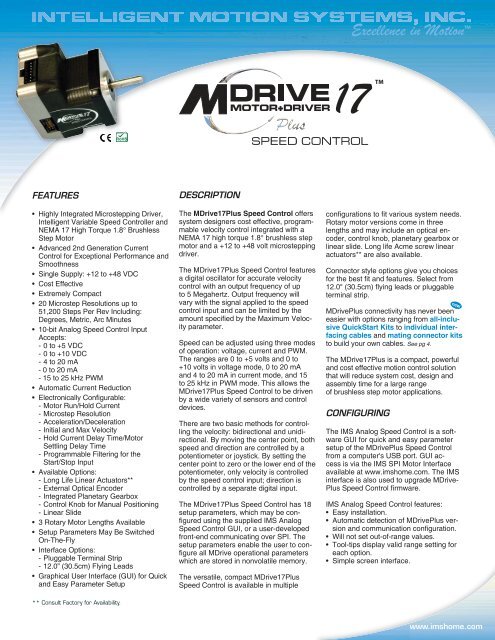
<strong>Excellence</strong> <strong>in</strong> <strong>Motion</strong>TM17TMSPEED CONTROLFEATURES• Highly Integrated Microstepp<strong>in</strong>g Driver,Intelligent Variable Speed Controller andNEMA 17 High Torque 1.8° BrushlessStep Motor• Advanced 2nd Generation CurrentControl for Exceptional Performance andSmoothness• S<strong>in</strong>gle Supply: +12 to +48 VDC• Cost Effective• Extremely Compact• 20 Microstep Resolutions up to51,200 Steps Per Rev Includ<strong>in</strong>g:Degrees, Metric, Arc M<strong>in</strong>utes• 10-bit Analog Speed Control InputAccepts:- 0 to +5 VDC- 0 to +10 VDC- 4 to 20 mA- 0 to 20 mA- 15 to 25 kHz PWM• Automatic Current Reduction• Electronically Configurable:- Motor Run/Hold Current- Microstep Resolution- Acceleration/Deceleration- Initial and Max Velocity- Hold Current Delay Time/MotorSettl<strong>in</strong>g Delay Time- Programmable Filter<strong>in</strong>g for theStart/Stop Input• Available Options:- Long Life L<strong>in</strong>ear Actuators**- External Optical Encoder- Integrated Planetary Gearbox- Control Knob for Manual Position<strong>in</strong>g- L<strong>in</strong>ear Slide• 3 Rotary Motor Lengths Available• Setup Parameters May Be SwitchedOn-The-Fly• Interface Options:- Pluggable Term<strong>in</strong>al Strip- 12.0” (30.5cm) Fly<strong>in</strong>g Leads• Graphical User Interface (GUI) for Quickand Easy Parameter SetupDESCRIPTIONThe MDrive17Plus Speed Control offerssystem designers cost effective, programmablevelocity control <strong>in</strong>tegrated with aNEMA 17 high torque 1.8° brushless stepmotor and a +12 to +48 volt microstepp<strong>in</strong>gdriver.The MDrive17Plus Speed Control featuresa digital oscillator for accurate velocitycontrol with an output frequency of upto 5 Megahertz. Output frequency willvary with the signal applied to the speedcontrol <strong>in</strong>put and can be limited by theamount specifi ed by the Maximum Velocityparameter.Speed can be adjusted us<strong>in</strong>g three modesof operation: voltage, current and PWM.The ranges are 0 to +5 volts and 0 to+10 volts <strong>in</strong> voltage mode, 0 to 20 mAand 4 to 20 mA <strong>in</strong> current mode, and 15to 25 kHz <strong>in</strong> PWM mode. This allows theMDrive17Plus Speed Control to be drivenby a wide variety of sensors and controldevices.There are two basic methods for controll<strong>in</strong>gthe velocity: bidirectional and unidirectional.By mov<strong>in</strong>g the center po<strong>in</strong>t, bothspeed and direction are controlled by apotentiometer or joystick. By sett<strong>in</strong>g thecenter po<strong>in</strong>t to zero or the lower end of thepotentiometer, only velocity is controlledby the speed control <strong>in</strong>put; direction iscontrolled by a separate digital <strong>in</strong>put.The MDrive17Plus Speed Control has 18setup parameters, which may be configured us<strong>in</strong>g the supplied IMS AnalogSpeed Control GUI, or a user-developedfront-end communicat<strong>in</strong>g over SPI. Thesetup parameters enable the user to configure all MDrive operational parameterswhich are stored <strong>in</strong> nonvolatile memory.The versatile, compact MDrive17PlusSpeed Control is available <strong>in</strong> multipleconfi gurations to fi t various system needs.Rotary motor versions come <strong>in</strong> threelengths and may <strong>in</strong>clude an optical encoder,control knob, planetary gearbox orl<strong>in</strong>ear slide. Long life Acme screw l<strong>in</strong>earactuators** are also available.Connector style options give you choicesfor the best fi t and features. Select from12.0" (30.5cm) fl y<strong>in</strong>g leads or pluggableterm<strong>in</strong>al strip.MDrivePlus connectivity has never beeneasier with options rang<strong>in</strong>g from all-<strong>in</strong>clusiveQuickStart Kits to <strong>in</strong>dividual <strong>in</strong>terfac<strong>in</strong>gcables and mat<strong>in</strong>g connector kitsto build your own cables. See pg 4.The MDrive17Plus is a compact, powerfuland cost effective motion control solutionthat will reduce system cost, design andassembly time for a large rangeof brushless step motor applications.CONFIGURINGnewThe IMS Analog Speed Control is a softwareGUI for quick and easy parametersetup of the MDrivePlus Speed Con trolfrom a computer's USB port. GUI accessis via the IMS SPI Motor In ter faceavailable at www.imshome.com. The IMS<strong>in</strong>terface is also used to upgrade MDrive-Plus Speed Control fi rmware.IMS Analog Speed Control features:• Easy <strong>in</strong>stallation.• Automatic detection of MDrivePlus versionand communication confi guration.• Will not set out-of-range values.• Tool-tips display valid range sett<strong>in</strong>g foreach option.• Simple screen <strong>in</strong>terface.** Consult Factory for Availability.www.imshome.com
MDrive17Plus SPEED CONTROLSTANDARD SPEC I FI CA TIONSINPUT VOLTAGE (+V) Range+12 to +48 VDCPower supply current requirements = 2A (maximum) per MDrive17Plus.Actual power supply current will depend on voltage and load.SPEED CONTROLInput0 to +5 VDC*, 0 to +10 VDC, 4 to 20 mA, 0 to 20 mA or 15 to 25 kHz PWMA/D Resolution10 bitLow Level0 to +0.8 VDCLOGIC INPUT Start/Stop and Direction High Level+2.0 to +5.0 VDCInternal Pull-up Resistance (to +3.3 VDC) 20 kΩOscillator Frequency (Max) 5 MHzNumber of Sett<strong>in</strong>gs 20MOTION200, 400, 800, 1000, 1600, 2000, 3200, 5000,Microstep Resolution6400, 10000, 12800, 20000, 25000, 25600,Steps Per Revolution40000, 50000, 51200, 36000 (0.01 deg/µstep),21600 (1 arc m<strong>in</strong>ute/µstep), 25400 (0.001mm/µstep)THERMAL Operat<strong>in</strong>g TemperatureHeat S<strong>in</strong>k–40° to +85°C (non-condens<strong>in</strong>g)Motor–40° to +100°C (non-condens<strong>in</strong>g)*10 k Ω potentiometer resistance.SETUP PARAMETERSFunction Range Units DefaultA1Analog Input Mode0 to +5 VDC, 0 to +10 VDC,4 to 20 mA, 0 to 20 mA, 15 to 25 kHz PWM— 0 to +5 VDCACCL Acceleration 91 to 1.5 X 10 9 steps/second 2 1,000,000C Joystick Center 1 to 1022 counts 0DB Analog Deadband 0 to 255 counts 1DECL Deceleration 91 to 1.5 X 10 9 steps/second 2 1,000,000DIR Motor Direction Override Clockwise (CW) / Counterclockwise (CCW) — CWFAULT Fault/Checksum Error Error Code — NoneFS Analog Full Scale 1 to 1023 counts 1023HCDT Hold Current Delay Time HCDT + MSDT
MOTOR PERFORMANCE — Speed-TorqueTorque <strong>in</strong> Oz-In6050403020100S<strong>in</strong>gle Length Rotary Motor Double Length Rotary Motor Triple Length Rotary Motor24 VDC48 VDC0 1000 2000 3000 4000 5000 6000 7000(300) (600) (900) (1200) (1500) (1800) (2100)Speed <strong>in</strong> Full Steps per Second (RPM)42352821147Torque <strong>in</strong> N-cmTorque <strong>in</strong> Oz-In605040302010024 VDC48 VDC0 1000 2000 3000 4000 5000 6000 7000(300) (600) (900) (1200) (1500) (1800) (2100)Speed <strong>in</strong> Full Steps per Second (RPM)42352821147Torque <strong>in</strong> N-cmTorque <strong>in</strong> Oz-In6050423540302028211410024 VDC48 VDC70 1000 2000 3000 4000 5000 6000 7000(300) (600) (900) (1200) (1500) (1800) (2100)Speed <strong>in</strong> Full Steps per Second (RPM)Torque <strong>in</strong> N-cmWIRE/PIN ASSIGNMENTS — MDrive17Plus Speed ControlPluggableTerm<strong>in</strong>al StripP1: I/O & POWER CONNECTORFly<strong>in</strong>g LeadsWire ColorsFunctionP<strong>in</strong> 1 Violet Start/ Stop InputP<strong>in</strong> 2 Blue CW/CCW Direction InputP<strong>in</strong> 3 Green Speed Control InputP<strong>in</strong> 4 Yellow +5 VDC OutputP<strong>in</strong> 5 Gray Logic GroundP<strong>in</strong> 6 Black Power GroundP<strong>in</strong> 7 Red +V (+12 to +48 VDC)P2: COMM CONNECTOR (SPI)10-P<strong>in</strong> IDC 10-P<strong>in</strong> Wire Crimp FunctionP<strong>in</strong> 1 P<strong>in</strong> 9 No ConnectP<strong>in</strong> 2 P<strong>in</strong> 10 No ConnectP<strong>in</strong> 3 P<strong>in</strong> 7 No ConnectP<strong>in</strong> 4 P<strong>in</strong> 8 SPI Chip SelectP<strong>in</strong> 5 P<strong>in</strong> 5 Communications GroundP<strong>in</strong> 6 P<strong>in</strong> 6 +5 VDC OutputP<strong>in</strong> 7 P<strong>in</strong> 3 SPI Master Out – Slave InP<strong>in</strong> 8 P<strong>in</strong> 4 SPI ClockP<strong>in</strong> 9 P<strong>in</strong> 1 No ConnectP<strong>in</strong> 10 P<strong>in</strong> 2 SPI Master In – Slave OutMECHANICAL SPECIFICATIONSDimensions <strong>in</strong> Inches (mm)1.19(30.2)ConnectorOptionP10.08(2.0)0.94 ±0.02(23.9 ±0.5)0.59 ±0.02(15.0 ±0.5)Ø 0.1968 +0/-0.0005(Ø 4.999 +0/-0.013)4X M3x0.5 THREADx0.15 MIN DEEP2.30(58.3)P2ConnectorOption0.177 ±0.002(4.49 ±0.05)L MAXL MAX2Ø 0.866 +0/-0.002(Ø 21.996 +0/-0.051)1.68 SQ.(42.7 SQ.)P1 Connector OptionsI/O & PowerI/O & Power1.220 ±0.004 SQ.(31.0 ±0.1 SQ.)MDrive Lengths Inches (mm)LMAXSINGLE SHAFT or LINEARACTUATOR VERSIONS<strong>in</strong>gle 2.20 (55.9) 2.79 (70.9)Double 2.43 (61.7) 3.02 (76.7)Triple 2.77 (70.4) 3.37 (85.6)MotorLengthLMAX2CONTROL KNOB orENCODER VERSIONL MAX2 OptionsØ 0.97(Ø 24.6)DifferentialEncoder*S<strong>in</strong>gle-EndEncoder1.42(36.1)2.04*(51.8)P112.00 +1.0/-0.0(304.8 +25.4/-0.0)Fly<strong>in</strong>g LeadsP2 Connector OptionsP2CommP10.44(11.2)7-P<strong>in</strong> Pluggable ClampType Term<strong>in</strong>al StripP2CommConnectivity details:www.imshome.com/cables_cordsets.htmlControl Knob.1.20(30.4).1.22*(31.0)Encoder10-P<strong>in</strong> IDC10-P<strong>in</strong> Friction LockWire CrimpMDrive17Plus Speed Control REV060208 3
ORDER INFORMATION — MDrive17Plus Speed ControlCONNECTIVITY CONNECTINGnewnewnewQuickStart KitFor rapid design verification, all-<strong>in</strong>clusive QuickStart Kits have communicationconverter, prototype development cable(s), <strong>in</strong>structionsand CD for MDrivePlus <strong>in</strong>itial functional setup and system test<strong>in</strong>g.Communication ConvertersElectrically isolated, <strong>in</strong>-l<strong>in</strong>e con vert ers pre-wired with mat<strong>in</strong>g connectorsto conveniently set/program communication parameters for as<strong>in</strong>gle MDrivePlus via a PC's USB port. Length 12.0' (3.6m).Mates to connector:10-P<strong>in</strong> IDC ............................................MD-CC300-00110-P<strong>in</strong> Wire Crimp .................................MD-CC302-001Mat<strong>in</strong>g Connector KitsUse to build your own cables. Kit conta<strong>in</strong>s 5 mat<strong>in</strong>g shells with p<strong>in</strong>s.Cable not supplied. Manufacturer's crimp tool recommended.Mates to connector:10-P<strong>in</strong> Wire Crimp .................................CK-02Kit conta<strong>in</strong>s 5 mat<strong>in</strong>g connectors that press fit onto ribbon cable.Cable not supplied.10-P<strong>in</strong> IDC ............................................CK-01** Consult Factory for Availability.Connectivity details: www.imshome.com/cables_cordsets.htmlPART NUMBERINGOPTIONS OPTIONSL<strong>in</strong>ear Actuator**The MDrive17Plus is offered with numerous l<strong>in</strong>ear actuatorstyles and options to satisfy a broad range of l<strong>in</strong>ear motionapplications. Contact the factory for details or see:www.imshome.com/mdriveplus_l<strong>in</strong>ear_actuator.htmlExternal EncoderExternal optical encoders, s<strong>in</strong>gle-end or differential, areoffered factory-mounted with the MDrive17Plus. Referto the Encoder Specifications section for available l<strong>in</strong>ecounts. All encoders come with an <strong>in</strong>dex mark.Optional encoder cables are available. Order separately.S<strong>in</strong>gle-end Cable (12.0"/30.5cm) ............ES-CABLE-2Differential Lock<strong>in</strong>g Cable (6.0'/1.8mm) ......ED-CABLE-6Control KnobThe MDrive17Plus Speed Control is available with a factorymountedrear control knob for manual shaft position<strong>in</strong>g.Planetary GearboxEfficient, low ma<strong>in</strong>tenance planetary gearboxes areoffered assembled with the MDrive17Plus. Refer todetails and part numbers on the back cover.L<strong>in</strong>ear SlideIntegrated l<strong>in</strong>ear slides are available factory <strong>in</strong>stalled forprecision l<strong>in</strong>ear movement. Screw leads are 0.1", 0.2", 0.5"or 1.0" of travel per rev. Slides are 12.0" (30.5cm) to 36.0"(91.44cm) long. Contact factory for custom lengths. Referto separate datasheet or web site for complete details.Plusbase version**Consult Factory for Availability.KMDO1 S 17 4 –QuickStart Kitdetails aboveP1: I/O & PowerF = 12" Fly<strong>in</strong>g LeadsP = Pluggable ClampType Term<strong>in</strong>al StripOPTIONMotorA = S<strong>in</strong>gle Length & L<strong>in</strong>ear Actuator**B = Double LengthC = Triple LengthP2: CommunicationsD = SPI with 10-P<strong>in</strong> IDC ConnectorL = SPI with 10-P<strong>in</strong> Friction Lock WireCrimp ConnectorExample #1: Part Number MDO1PSD17A4 is an MDrive17Plus SpeedControl with pluggable I/O & power <strong>in</strong>terface, SPI communications with10-p<strong>in</strong> IDC connector, and NEMA 17 s<strong>in</strong>gle length motor.OPTIONSL<strong>in</strong>earActuator** –LFor complete product specifications, see:www.imshome.com/mdriveplus_l<strong>in</strong>ear_actuator.htmlExternalEncoder –ERefer to encoder specifications section for l<strong>in</strong>e counts and part numbers.Example: MDO1PSD17A4–EHL adds an external 500-l<strong>in</strong>e countdifferential optical encoder with <strong>in</strong>dex mark to example #1.ControlKnob –NExample: MDO1PSD17A4–N adds a rear control knob for manualposition<strong>in</strong>g to example #1.PlanetaryGearbox – G – F Optional NEMA FlangeRefer to gearbox page for complete table of ratios and part numbers.Example: MDO1PSD17A4–G1A2 adds a 1-stage planetary gearboxwith 5.18:1 ratio to example #1. Add –F for optional NEMA flange.L<strong>in</strong>earSlide –RScrew Lead(<strong>in</strong>ches/rev)A = 0.10” (2.54mm)B = 0.20” (5.08mm)C = 0.50” (12.7mm)D = 1.00” (25.4mm)Standard Screw Lengths10", 12", 15", 18", 24" or 36"For Custom Lengths, Consult FactoryNOTE: 10" lengths only with A or B leads.15" lengths only with A, B or C leads.36" lengths only with D leads.Example: MDO1PSD17A4–RA10 adds a L<strong>in</strong>ear Slide with0.10" screw lead, 10" long to example #1.4 MDrive17Plus Speed Control REV060208
MDRIVE17PLUS WITH PLANETARY GEARBOXThe MDrive17Plus is available with a Planetary Gearbox option developed to <strong>in</strong>crease torque at lower speeds, enable better <strong>in</strong>ertiamatch<strong>in</strong>g and produce f<strong>in</strong>er positional resolutions. These efficient, low ma<strong>in</strong>tenance Planetary Gearbox come fully assembled withthe MDrive and are offered <strong>in</strong> a large number of reduction ratios <strong>in</strong> 1-, 2- and 3-stage configurations. An optional NEMA OutputFlange allows mount<strong>in</strong>g the Planetary Gearbox to the load us<strong>in</strong>g a standard NEMA bolt circle. Planetary Gearbox may be comb<strong>in</strong>edwith other MDrive17Plus options, however are unavailable with L<strong>in</strong>ear Actuators.Planetary Gearbox ParametersPermittedOutput Torque(oz-<strong>in</strong>/Nm)GearboxEfficiencyMaximumBacklashOutput Side with Ball Bear<strong>in</strong>gMaximum Load(lb-force/N)Weight(oz/g)Radial Axial Gearbox with Flange1-STAGE 425/3.0 0.80 0.80° 36/160 11/50 14.3/406 14.8/4202-STAGE 1062/7.5 0.75 0.85° 52/230 18/80 17.9/508 18.5/5253-STAGE 2124/15.0 0.70 0.90° 67.5/300 25/110 18.5/525 22.2/630Planetary Gearbox for MDrive17PlusDimensions <strong>in</strong> Inches (mm)*Gearbox without Flange† Gearbox with Flange0.984*(25.0)orM3 x 0.276 (7.0) Deep †M4 x 0.394 (10.0) Deep*0.08M3 x 0.394 (10.0) Deep*(2.0)1.657 SQ.(42.1 SQ.)1.22 †(31.0)Ø 1.26*(Ø 32.0)Ø 1.417*(Ø 36.0)Ø 0.984* or 0.866 †(Ø 25.0* or 22.0 †)+0/-0.002 (+0/-0.052)Ø 0.315 +0/-0.0004(Ø 8.0 +0/-0.009)Ctrg.DIN 332-DM3Key DIN 6885-A-3x3x16mm0.846 †(21.5) k1 ±0.02 (±0.5)Ø 1.654(Ø 42.0)1.20(30.5)MDrive17PlusGearbox Lengths Inches (mm)k1GEARBOX* with FLANGE †1-Stage 2.736 (69.5) 2.858 (72.6)2-Stage 3.248 (82.5) 3.37 (85.6)3-Stage 3.76 (95.5) 3.882 (98.6)Ratios and Part NumbersPlanetaryGearboxRatio(Rounded)PartNumber**1-Stage 3.71:1 G1A11-Stage 5.18:1 G1A21-Stage 6.75:1 G1A32-Stage 13.73:1 G1A42-Stage 15.88:1 G1A52-Stage 18.37:1 G1A62-Stage 19.20:1 G1A72-Stage 22.21:1 G1A82-Stage 25.01:1 G1A92-Stage 26.85:1 G1B12-Stage 28.93:1 G1B22-Stage 34.98:1 G1B32-Stage 45.56:1 G1B43-Stage 50.89:1 G1B53-Stage 58.86:1 G1B63-Stage 68.07:1 G1B73-Stage 71.16:1 G1B83-Stage 78.72:1 G1B93-Stage 92.70:1 G1C13-Stage 95.18:1 G1C23-Stage 99.51:1 G1C33-Stage 107.21:1 G1C43-Stage 115.08:1 G1C53-Stage 123.98:1 G1C63-Stage 129.62:1 G1C73-Stage 139.14:1 G1C83-Stage 149.90:1 G1C93-Stage 168.85:1 G1D13-Stage 181.25:1 G1D23-Stage 195.27:1 G1D33-Stage 236.10:1 G1D43-Stage 307.55:1 G1D5**Include optional planetary gearbox by add<strong>in</strong>g –G plus3 characters to the end of an MDrive part number.U.S.A. SALES OFFICESEastern RegionTel. 862 208-9742 - Fax 973 661-1275e-mail: jroake@imshome.comCentral RegionTel. 260 402-6016 - Fax 419 858-0375e-mail: dwaksman@imshome.comWestern RegionTel. 602 578-7201e-mail: dweisenberger@imshome.comIMS ASIA PACIFIC OFFICE30 Raffles Pl., 23-00 Caltex House, S<strong>in</strong>gapore 048622Tel. +65/6233/6846 - Fax +65/6233/5044e-mail: wllee@imshome.comIMS EUROPEAN SALES MANAGEMENT4 Quai Des Etroits69005 Lyon, FranceTel. +33/4 7256 5113 - Fax +33/4 7838 1537e-mail: bmart<strong>in</strong>ez@imshome.comIMS UK Ltd.Sanderson Centre, 15 Lees LaneGosport, Hampshire PO12 3ULTel. +44/0 2392-520775 - Fax +44/0 2392-502559e-mail: mcheckley@imshome.comTECHNICAL SUPPORTTel. +00 (1) 860 295-6102 - Fax +00 (1) 860 295-6107e-mail: etech@imshome.comIntelligent <strong>Motion</strong> Systems, Inc.370 North Ma<strong>in</strong> Street, P.O. Box 457Marlborough, CT 06447 - U.S.A.Tel. +00 (1) 860 295-6102 - Fax +00 (1) 860 295-6107e-mail: <strong>in</strong>fo@imshome.comhttp: //www.imshome.com© Intelligent <strong>Motion</strong> Systems, Inc. All Rights Reserved. REV060208IMS Product Disclaimer and most recent product <strong>in</strong>formation at www.imshome.com.
![[Instruction] Contents](https://img.yumpu.com/51325878/1/184x260/instruction-contents.jpg?quality=85)