BAKER Drive Brake Transmission Instructions, 2 ... - Baker Drivetrain
BAKER Drive Brake Transmission Instructions, 2 ... - Baker Drivetrain
BAKER Drive Brake Transmission Instructions, 2 ... - Baker Drivetrain
- No tags were found...

You also want an ePaper? Increase the reach of your titles
YUMPU automatically turns print PDFs into web optimized ePapers that Google loves.
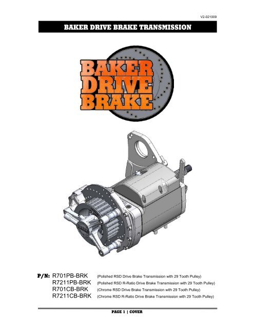
<strong>BAKER</strong> <strong>BAKER</strong> DRIVE CRUISE BRAKE DRIVE TRANSMISSIONTOP COVERV2-021009P/N: R701PB-BRKR7211PB-BRKR701CB-BRK(Polished RSD <strong>Drive</strong> <strong>Brake</strong> <strong>Transmission</strong> with 29 Tooth Pulley)(Polished RSD R-Ratio <strong>Drive</strong> <strong>Brake</strong> <strong>Transmission</strong> with 29 Tooth Pulley)(Chrome RSD <strong>Drive</strong> <strong>Brake</strong> <strong>Transmission</strong> with 29 Tooth Pulley)R7211CB-BRK (Chrome RSD R-Ratio <strong>Drive</strong> <strong>Brake</strong> <strong>Transmission</strong> with 29 Tooth Pulley)PAGE 1 | COVER
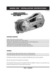
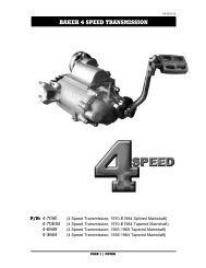
FEATURESV2-021009<strong>BAKER</strong> DRIVE BRAKE TRANSMISSION OVERVIEWMost riders customize their bikes with wheels and paint to set it apart from the masses. We sayshow off that rear wheel you just spent thousands on with the new <strong>BAKER</strong> <strong>Drive</strong> <strong>Brake</strong><strong>Transmission</strong> that features a fully show polished or chrome complete RSD Billet <strong>Transmission</strong>assembly. Ditching convention and forging our own path as we often do, an 8” stainless steelrotor and dual piston caliper design with dual bleeders come standard. The biggest diametertransmission mounted brake rotor on the market gives you the stopping power to slide the rearwheel out with this bad boy. The Function Formed RSD hydraulic actuator with a 1.500” pistonbore and polished Stainless steel standoffs, leaves your rear wheel how it should be, seen!Available for EVO Softail ® -based applications as a Standard or R-Ratio right side drive 6-speedAdditional options include N-1 Drum for those who hate trying to find neutral, A 29 tooth, .500”offset belt pulley come standard. Depending on the application or look that you are after, the topcovers come with or without a neutral switch provision and case comes with or without Speedohole.FITMENT• 1984-1999 EVO Softail ®• Custom ApplicationsTOOLS REQUIRED• Torque Wrench (reads both in. lbs. and ft. lbs.)• 6 Point Deep Well ¼” <strong>Drive</strong> Sockets• 3/16” Spanner Wrench• Common Hand Held Tools (Allen Wrenches, Sockets, Snap Ring Pliers, Etc.)• Inner Primary Race Service Toolo <strong>BAKER</strong> P/N TOOLB-56o H-D ® Equivalent P/N 34902A• Main <strong>Drive</strong> Gear & Bearing Service Toolso <strong>BAKER</strong> P/N Tool A-56o H-D ® Equivalent P/N 35316ASPECIFICATIONS• TRANSMISSION FLUID CAPACITY: 22-24 fluid oz. <strong>BAKER</strong> Recommends: Spectro HeavyDuty Platinum 6 Speed <strong>Transmission</strong> Oil, P/N R.HDPG6• COUNTERSHAFT END PLAY: .006”-.010”• SHIFT DRUM END PLAY: .000” (not adjustable)• PAWL ADJUSTMENT: In 3 rd Gear measurement must be equal to within .010” between pinsGEAR RATIOSSTANDARDR-RATIO1 ST 2.94 1 ST 2.822 ND 2.21 2 ND 2.083 RD 1.60 3 RD 1.604 TH 1.23 4 TH 1.235 TH 1.00 5 TH 1.006 TH 0.86 6 TH 0.86PAGE 2 | OVERVIEW - SPECIFICATIONS
V2-021009<strong>BAKER</strong> DRIVE BRAKE TRANSMISSIONTABLE OF CONTENTS:2) Overview3) Table Of Contents4) Torque Values5) Included Parts Breakdown Figure 16) Included Parts Breakdown Figure 1 Legend7) Included Parts Breakdown Figure 28) Included Parts Breakdown Figure 2 Legend9) Included Parts Breakdown and Legend Figure 310) Installation, Bleeding of Rear <strong>Brake</strong>11) Bleeding Rear <strong>Brake</strong> Continued, Bleeding of Clutch12) Bleeding of Clutch Continued, Maintenance13) Maintenance Continued14) Maintenance Continued15) Terms16) DisclaimerPAGE 3 | TABLE OF CONTENTS
<strong>BAKER</strong> DRIVE BRAKE TORQUE VALUESV2-021009TORQUE VALUESTHREADLOCKER / LUBRICANTACTUATOR• 3/8-16 Bolt: 200-225 in-lbs (16-18 ft-lbs) Blue Loctite (242 Removable)BEARING DOOR / CALIPER / FENDER SUPPORT• 5/16-18 Bolts: 200-225 in-lbs (16-18 ft-lbs) Blue Loctite (242 Removable)TOP COVER• 1/4-20 Bolts: 100-120 in-lbs (8-10 ft-lbs) Blue Loctite (242 Removable)STARTER EAR• 5/16-18 Bolts: 200-225 in-lbs (16-18 ft-lbs) Blue Loctite (242 Removable)DRUM ASSEMBLY• 1/4-20 Bolts: 100-120 in-lbs (8-10 ft-lbs) Blue Loctite (242 Removable)LOCK PLATE (PULLEY NUT)• 1/4-20 Bolts: 100-120 in-lbs (8-10 ft-lbs) Blue Loctite (242 Removable)PULLEY / SPROCKET NUT• 50 ft-lbs (67.8 Nm) initial torque, then turn another 30-40 degrees; 45 degrees max.Red Loctite (271 Permanent)ECCENTRIC SCREW JAM NUT• 240-288 in-lbs (20-24 ft-lbs) Blue Loctite (242 Removable)SHIFT LEVER• 5/16-24 Bolt: 200-225 in-lbs (16-18 ft-lbs) Blue Loctite (242 Removable)NUT, LEFT SIDE SEAL• 100 ft-lbs (135.58 Nm) Red Loctite (271 Permanent)COUNTERSHAFT CAP• Snug with 3/16” Spanner Wrench Pipe Thread SealantFILL PLUG• 30-40 in-lbs Anti-SeizeDRAIN AND LEVEL PLUG• 30-40 in-lbs Anti-Seize10MM BANJO BOLTS• 17-22 ft-lbs (23.0-29.8 Nm)BLEEDER SCREWS• 80 in-lbsROTOR BOLT NUTS• 5/16-24 Nut: 200-225 in-lbs (16-18 ft-lbs) Red Loctite (271 Permanent)PAGE 4 | TORQUE VALUES
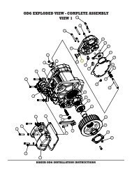
<strong>BAKER</strong> DRIVE BRAKE EXPLODED VIEWSV2-021009FIGURE 1PAGE 5 | EXPLODED VIEW 1
<strong>BAKER</strong> DRIVE BRAKE PARTS DETAIL FIGURE 1V2-021009ITEM QTY P/N DESCRIPTION1 2 37C250KCSS/P 3/8-16 x 2.500” Polished SHCS2 1 114R-BRKP/C RSD Hydraulic Actuator3 1 37C100KCSS/P 3/8-16 x 1.000” Polished SHCS4 3 45-9404 Bleeder Valve5 3 31C125KCSS/P 5/16-18 x 1.250” Polished SHCS6 1 106R-BRKP/C <strong>Brake</strong> Caliper7 2 0052-1200 <strong>Brake</strong> Piston Seal8 2 0052-1410 <strong>Brake</strong> Piston9 2 0052-1601ED <strong>Brake</strong> Pad10 1 124-5R 1.500” RSD Piston, Actuator11 2 66855 O-Ring, Hydraulic Piston12 1 10705-01149 C-Clip, Actuator Rod13 2 TWC411 Washer, Actuator Rod14 1 TC411 Bearing, Thrust, Actuator Rod15 1 3687 Seal, Actuator Rod16 1 126-56MR Actuator Rod17 5 31FNXUS 5/16-24 Expanding Lock Nut S.S.18 5 31NWSAS Washer, .347 I.D. / .683 O.D.19 2 108R-BRKP Standoff, Fender Support20 2 23202 1/4-20 x .625” SHCS21 1 35211-91B Nut, Pulley / Sprocket22 1 29BD-BRK 29 Tooth Pulley23 1 116R-BRKP Spacer, Pulley24 1 115R-BRK 8.000” <strong>Brake</strong> Rotor25 4 31C100KCSS/P 5/16-18 x 1.000” Polished SHCS26 1 105R-BRKP/C Fender Support27 5 31F125KFOZ 5/16-24 x 1.250” FHCS, Pulley28 4 23207 1/4-20 x 1.250” SHCS29 4 33001 Washer, Shift System30 1 33715-85S Shift Lever31 1 124E-OD6R-A OD6R Shift System32 1 31F100KCSS/P 5/16-24 x 1.000” Polished SHCS33 1 70813 7/16-14 Jam Nut34 1 152-56A Eccentric Screw35 1 62375-57C Vent, Top Cover36 1 25C175KCSS/P 1/4-20 x 1.750” Polished SHCS37 5 25C100KCSS/P 1/4-20 x 1.000” Polished SHCS38 1* 33902-98 98 Neutral Switch39 1 104I-56P/C / 104N-56P/C Top Cover40 1 104TG-56 Gasket, Top Cover41 6 609B Alignment Dowel42 1 66808 #014 Buna O-Ring43 1 132-56R Spacer, Speed Sensor44 1 108-6EP Plug, Speed Sensor45 1 73753 1/4-20 x .625” Polished BHCS46 1 12067B Seal, Door, Main Bottle Gear47 4 16583-00 10MM Alignment Dowel48 2 18R125PDO 3/16 x 1.250” Solid Dowel49 1 0073-0005 O-Ring, Caliper Seal50 1 33344-94 Spacer, Pulley / Spacer51 1 11165A Quad Seal52 1 PB14-6RP Cap, Countershaft53 1 24256 5/16-18 x 1.000” FHCS54 1 35020-89 Retainer, Countershaft55 Differ 98055A236 / 98055A234 Shims, Countershaft, Differ For Each56 1 143RRRI 1 7/16” Internal Snap Ring57 2 AS2035 Shim, Countershaft, Door* = CUSTOMER PREFERENCE, MAY NOT BE INCLUDEDPAGE 6 | EXPLODED VIEW 1 LEGEND
<strong>BAKER</strong> DRIVE BRAKE EXPLODED VIEWSV2-021009FIGURE 2PAGE 7 | EXPLODED VIEW 2
<strong>BAKER</strong> DRIVE BRAKE PARTS DETAIL FIGURE 2V2-021009ITEM QTY P/N DESCRIPTION1 1 37088-90 Clutch Release Rod2 1 See Figure 3 OD6R Gearset Assembly3 1 122-6R Fork Rod4 1 104B-56P/C Billet <strong>Transmission</strong> Case5 1 104D-GAS Gasket, Starter Ear6 1 104D-56P/C Billet Starter Ear7 1 26770 5/16” x 1.000” Dowel8 9 73495 5/16-18 x 1.000” S.S. SHCS9 1 192-OD6R Shift Fork, 2 nd Gear10 1 193-OD6R Shift Fork, 3 rd Gear11 1 191-OD6R Shift Fork, 1 st Gear12 1 555-56A Shifter Pawl Assembly13 2 6209 Bearing, Main Gear, Case14 2 1302-334PP Beveled Snap Ring15 1 12067B Seal, Case16 1 SK-2645 Nut, Adapter, Left Side Seal17 1 66832 O-Ring, #120 Buna18 1 68010 7/16” External Snap Ring19 1 6497HW Washer, Shifter Pawl20 1 12045 Seal, Shifter Pawl21 1 33114-79 Bushing, Shifter Pawl22 1 BK2526 Bearing, Case23 4 26751 1/4” x 3/4" Solid Dowel24 5 11733A Stud, Case25 6 73497 5/16-18 x 1.500” S.S. SHCS26 2 73464 1/4-20 x 1.500” S.S. SHCS27 1 51740-001 3/8-24, Drain Plug28 1 31588 1/8” NPT, Level Plug29 1 3784C 1/2-20 Plug, Fork Rod30 1 104R-BRKP/C Bearing Door31 1 22S-S06CLR 9/16-18, Fill Plug32 1 104CG-56-.060 Gasket, Bearing Door33 1 12035B Seal, Main Gear34 1 F1409 Magnet, Bearing Door35 1 23205 1/4-20 x 1.000” SHCS36 3 HK2520 Bearing, Main <strong>Drive</strong> Gear / Case37 1 61005M 5 th Gear, Main <strong>Drive</strong>PAGE 8 | EXPLODED VIEW 2 LEGEND
V2-021009<strong>BAKER</strong> DRIVE BRAKE EXPLODED VIEWSFIGURE 3ITEM QTY P/N DESCRIPTION1 1 OD6R-2M / OD6R-2M208 2 nd Gear, Mainshaft2 5 11067A Retaining Ring3 6 6003B Thrust Washer4 1 OD6R-3M 3 rd Gear, Mainshaft5 5 8876A Bearing, Caged Needle6 1 OD6R-4M 4 th Gear, Mainshaft7 1 DD6-4C5 Dog Clutch8 1 OD6R-6M 6 th Gear, Mainshaft9 1 SK-2644 Collet, Mainshaft10 1 OD6R-MS / OD6R-MS282 Mainshaft11 1 OD6R-CS Countershaft12 1 OD6R-4C 4 th Gear, Countershaft13 1 OD6R-1C / OD6R-1C282 1 st Gear, Countershaft14 1 OD6R-3C 3 rd Gear, Countershaft15 1 OD6R-2C / OD6R-2C208 2 nd Gear, Countershaft16 1 61005C 5 th Gear, Countershaft17 1 15162 Washer, .062” Thick HardenedPAGE 9 | GEARSET AND LEGEND
INSTALLATION:<strong>BAKER</strong> DRIVE BRAKE TRANSMISSIONPAGE 10 | INSTALLATIONV2-0210091) Install the <strong>Drive</strong> <strong>Brake</strong> <strong>Transmission</strong> per your Factory Service Manual without installing thestarter at this time.IT IS HIGHLY RECOMMEND THAT THE REAR BRAKE LINE BE INSTALLEDBEFORE INSTALLING THE STARTER. THIS WILL ALLOW ENOUGH ROOM FORPROPER LINE INSTALLATION, DUE TO THE LOCATION OF THE FEED PORT.2) Install the rear brake line to the transmission with10MM banjo fitting (straight, 35, or 90 degree fitting),washers, and 3/8-24 banjo bolt. Make sure that routingof the line is secure and will not bind on swing arm orframe during riding conditions. Torque banjo bolt to 17-22 ft-lbs (23.0-29.8 Nm). Location on back side of doorsee figure 4.3) Install starter per your Factory Service Manual.The <strong>BAKER</strong> Firestarter will not work with the <strong>BAKER</strong><strong>Drive</strong> <strong>Brake</strong> <strong>Transmission</strong>.4) Remove the transmission hydraulic actuator to installthe rear belt. Install your rear belt and adjust per yourFactory Service Manual.5) Re-install the transmission hydraulic actuator asSHOWING BRAKE LINE FEED PORT FIGURE 4removed in step 4 using Blue Loctite (242Removable). Torque bolts to 200-225 in-lbs (16-18 ftlbs)using figure 1 for assembly reference.6) Install hydraulic actuator line using a 9/16” quarterinch drive socket; making sure that the routing of the linedoes not interfere with the exhaust or belt. Using a 90degree or 35 degree 10MM banjo fitting and a 3/8-24banjo bolt; torque to 17-22 ft-lbs (23.0-29.8 Nm). Seefigure 5.7) With the motorcycle being level, fill the transmissionwith 22-24 fluid oz of transmission fluid. Checktransmission fluid level by removing the 1/8” NPT levelplug located on the front side of the transmission door.When full the fluid will weep from hole; reinstall plugSHOWING HYDRAULIC LINE FIGURE 5using torque value chart on page 4. Refer to pages7-8 for location of level plug.BLEEDING THE HYDRAULIC BRAKE SYSTEM<strong>BAKER</strong> DRIVETRAIN MAKES THE STRONG RECOMMENDATION THAT APOWER BLEEDER SYSTEM BE UTILIZED, WHETHER THAT IS A HANDOPERATED PUMP OR PNEUMATIC, TO BLEED THE HYDRAULIC BRAKESYSTEM ON YOUR MOTORCYCLE. IT IS THE MOST EFFECTIVE AND ONLYSUREFIRE WAY TO ENSURE THAT ALL OF THE AIR BUBBLES ARE PURGEDFROM THE SYSTEM. IF YOU DO NOT OWN A POWER BLEEDER, THEFOLLOWING SET OF INSTRUCTIONS WILL ENABLE YOU TO BLEED YOURCLUTCH SYSTEM. GREAT CARE AND ATTENTIONS NEEDS TO USED INFOLLOWING THESE STEPS TO ENSURE A PROPERLY BLED AND FUNCTIONINGSYSTEM TO ENSURE YOUR SAFETY AS A RIDER.(CONTINUED ON NEXT PAGE)
<strong>BAKER</strong> DRIVE BRAKE TRANSMISSIONV2-0210091) There are 2 bleeders on the brake; 1 on the door and 1 on the caliper. 1 st bleed the caliper byusing a 1/4" socket for a 1/4" drive ratchet. Place a clear tube over the bleeder valve on thecaliper and run it into a clean container.2) Stand the motorcycle upright so that the master cylinder on the rear brake lever is level.Remove the master cylinder lid and gasket.3) Add new DOT 5 Silicone <strong>Brake</strong> Fluid to the master cylinder reservoir under to the fluid level isat or below the full line. DO NOT OVERFILL THE MASTER CYLINDER4) Squeeze the lever 5-10 times. Open the bleeder valve on the caliper and brake fluid shouldflow through the tubing. If not, keep pumping the lever as it may take a few minutes for the fluid tomake it all of the way through the line and cover. Once fluid begins to flow through the clear tube,close the bleeder valve. It may be necessary to add more fluid during this time even before anyfluid begins to flow out of the clear tubing.5) Squeeze the brake lever and hold it in the down position to build up hydraulic pressure. Openthe bleeder valve on the caliper about ½ turn. <strong>Brake</strong> fluid will flow through the clear tubing. Closethe bleeder when the brake lever has traveled about 50-75% of its full travel. Wait for the brakelever to return to its released position. Repeat step 5 as necessary until all air bubbles have beenforced out of the system and there is no bubbles in the fluid within the clear tubing.6) Now bleed the system from the door side repeating steps 2-5. When the system has been fullybled and the brake lever no longer feels mushy, fully tighten the bleeder valve on the caliper anddoor to 80 in-lbs. It may be necessary to fill the fluid in the reservoir to the full line at this time. DONOT OVERFILL THE MASTER CYLINDER.7) Place the cover back on the master cylinder and tighten down according to the controlmanufacturer’s specifications. Check to make sure that the brake line is tight at the brake leverand the door at this time.BLEEDING THE HYDRAULIC CLUTCH SYSTEM<strong>BAKER</strong> DRIVETRAIN MAKES THE STRONG RECOMMENDATION THAT APOWER BLEEDER SYSTEM BE UTILIZED, WHETHER THAT IS A HANDOPERATED PUMP OR PNEUMATIC, TO BLEED THE HYDRAULIC CLUTCHSYSTEM ON YOUR MOTORCYCLE. IT IS THE MOST EFFECTIVE AND ONLYSUREFIRE WAY TO ENSURE THAT ALL OF THE AIR BUBBLES ARE PURGEDFROM THE SYSTEM. IF YOU DO NOT OWN A POWER BLEEDER, THEFOLLOWING SET OF INSTRUCTIONS WILL ENABLE YOU TO BLEED YOURCLUTCH SYSTEM. GREAT CARE AND ATTENTIONS NEEDS TO USED INFOLLOWING THESE STEPS TO ENSURE A PROPERLY BLED AND FUCNTIONINGSYSTEM TO ENSURE YOUR SAFETY AS A RIDER.1) Before you can bleed the Hydraulic Clutch system you need to adjust the free play and rodlength at the clutch. Using an Allen wrench, run the adjuster bolt (center of the clutch) inboarduntil it can be felt to bottom the piston out in the side cover. You will also know that you have hitthe bottom point as the clutch will begin the move. At the point where it is fully bottomed out, backthe adjuster off ½ to 1 full turn. The closer to the 1 full turn point that you adjust it too, the morereserve you will have in the lever before the motorcycle begins to move, with the full engagementof the clutch being proportionally closer to the end of the sweep of the lever. This amount can beadjusted to rider comfort and riding style. Tighten the jam nut to 120 in-lbs while holding theadjuster screw from rotating.2) Place a clear tube over the bleeder valve on the hydraulic actuator and run it into a cleancontainer.(CONTINUED ON NEXT PAGE)PAGE 11 | BLEEDING PROCEEDURES
<strong>BAKER</strong> DRIVE BRAKE TRANSMISSIONV2-0210093) Stand the motorcycle upright so that the master cylinder on the clutch lever is level. Removethe master cylinder lid and gasket.4) Add new DOT 5 Silicone <strong>Brake</strong> Fluid to the master cylinder reservoir under to the fluid level isat or below the full line. DO NOT OVERFILL THE MASTER CYLINDER5) Squeeze the lever 5-10 times. Open the bleeder valve on the hydraulic actuator and clutchfluid should flow through the tubing. If not, keep pumping the lever as it may take a few minutesfor the fluid to make it all of the way through the line and cover. Once fluid begins to flow throughthe clear tube, close the bleeder valve. It may be necessary to add more fluid during this timeeven before any fluid begins to flow out of the clear tubing.6) Squeeze the clutch lever and hold it against the handlebar to build up hydraulic pressure.Open the bleeder valve on the hydraulic actuator about ½ turn. Clutch fluid will flow through theclear tubing. Close the bleeder when the clutch lever has traveled about 50-75% of its full travel.Wait for the clutch lever to return to its released position. Repeat step 6 as necessary until all airbubbles have been forced out of the system and there is no bubbles in the fluid within the cleartubing.7) When the system has been fully bled and the clutch lever no longer feels mushy, fully tightenthe bleeder valve on the side cover to 80 in-lbs. It may be necessary to fill the fluid in the reservoirto the full line at this time. DO NOT OVERFILL THE MASTER CYLINDER.8) Place the cover back on the master cylinder and tighten down according to the controlmanufacturer’s specifications. Check to make sure that the clutch line is tight at the clutch leverand the hydraulic actuator at this time.9) Replace the derby cover on the primary, referring to the Factory Service Manual for the propertightening sequence.MAINTENANCE / SERVICE:<strong>BAKER</strong> RECOMMENDS CHECKING FOR BRAKE PAD WEAR AFTER THEFIRST 1000 MILES AND 5000 MILES THERE AFTER FOR THE PROPERFUNCTION OF YOUR DRIVE BRAKE TRANSMISSION.MINIMUM BRAKE PAD THICKNESS: .040” (1.02mm)MINIMUM ROTOR THICKNESS:.190” (4.826mm)MAXIMUM ROTOR LATERAL RUNOUT: .008” (0.2mm)<strong>BAKER</strong> DRIVETRAIN BRAKE PAD KIT: P/N BRK-KITPERFORMANCE MACHINE KITS:P/N 0052-1601EDP/N 0052-3001Tools Required• Pulley Nut Socketo <strong>BAKER</strong> P/N TOOLD-56o H-D ® Equivalent P/N 94660-37BTHE DRIVE BRAKE DUAL PISTON UTILIZES PERFORMANCE MACHINEINTERNAL COMPONENTS. IF PURCHASING THE P.M. BRAKE KIT; BOTH KITNUMBERS MUST BE PURCHASED.CHECKING BRAKE PAD WEARUsing a flash light or mirror check for any excessive pad wear and replace pads if necessary.Replace the brake pads if the friction material on either front or rear pad is worn to .040”(1.02mm) or less above the backing plate. Figures 6-7(CONTINUED ON NEXT PAGE)PAGE 12| BLEEDING PROCEEDURE / MAINTENANCE
<strong>BAKER</strong> DRIVE BRAKE TRANSMISSIONV2-021009ALWAYS REPLACE BRAKE PADS IN SETS FOR SAFE BRAKE OPERATION.IMPROPER BRAKE OPERATION COULD RESULT IN DEATH AND ORSERIOUS INJURY.BOTH PICTURES ARE SHOWING HOWTO CHECK FOR BRAKE PAD WEAR.FIGURE 6 LEFT PICTURE SHOWINGOUTBOARD BRAKE PADFIGURE 7 RIGHT PICTURE SHOWINGINBOARD BRAKE PADCHECKING BRAKE ROTOR WEARThe <strong>BAKER</strong> <strong>Drive</strong> <strong>Brake</strong> Rotor is designed to last the life time of the transmission, but due toroad grime, dirt roads, and your riding style you might find that your brake rotor will wear, showinggrooves or pulsate due to excessive heavy braking.Using a brake rotor micrometer measure the thickness in various areas to make sure that you arewithin the minimum rotor thickness of .190” (4.826mm). If the brake rotor is below the minimumthickness replace rotor. Reference exploded view Figure 1 for part numbers and description.Using a dial indicator measure lateral runout of the brake rotor; if lateral runout is above .008”total replace rotor. Reference exploded view Figure 1 for part numbers and description.BRAKE PAD REPLACEMENT1) Safety 1 st ; remove your seat and disconnect your battery;disconnecting your negative battery cable first.2) Remove your exhaust system; if it will interfere with removingthe hydraulic actuator.3) Remove your hydraulic clutch line from the hydraulic actuatorusing a 9/16” quarter inch drive socket. Remove the threeretaining bolts holding on your hydraulic actuator using a 5/16”Allen. Remove the hydraulic actuator and standoffs.4) Remove the hydraulic actuator front fender support andcaliper bolts; 1/4" Allen. Using the two 3/8-16 x 2.500” boltsremoved from the hydraulic actuator; thread the two bolts atleast a ½” into the fender support by hand, wiggle the fendersupport off of the bearing door (figure 8). Using the samemethod as before thread in one of the 3/8-16 x 2.500” bolts intothe caliper by hand until it bottoms out. Wiggle the caliper off ofthe bearing door (figure 9)5) Loosen the rear wheel and drive belt by referring to yourFactory Service Manual. Remove the two pulley lock screws andpulley nut; PULLEY NUT IS LEFT HAND THREAD. Remove thepulley /rotor assembly as seen in figure 10.(CONTINUED ON NEXT PAGE)REMOVING SUPPORT FIGURE 8REMOVING CALIPER FIGURE 9PAGE 13| MAINTENANCE
<strong>BAKER</strong> DRIVE BRAKE TRANSMISSIONV2-0210096) With the pulley and rotor assembly out of the way you canaccess the inside brake pad.7) Before removing the old brake pad press the pad inwardtoward the bearing door to fully compress the piston. Do thesame with the caliper you removed in step 4. This will allowenough clearance to install the new brake pads. Removeand discard old brake pads.8) Clean off the bearing door and caliper where the brakepads slide into with a rag to clean up all the residual brakefluid that might have seeped out during step 7.PULLEY AND ROTOR ASSEMBLY FIGURE 109) Install new inside brake pad; DURING INSTALLATIONMAKE SURE THAT THE NEW BRAKE PAD SLIDES FREELYON THE DOWELS AND INTO THE PAD POCKET. <strong>BAKER</strong> hasfound that some pads have an excessive amount of paintbuildup around the dowel holes or notch of the pad. Thisbuildup can be removed with a small file or screw driver.Figure 1110) Re-install the pulley and rotor assembly; making surethat you wrap the drive belt around the pulley duringinstallation. Referencing page 4 Torque Values; torquepulley nut and lock screws using the correct Loctite.11) Slide on the outside brake pad over the dowels until itsflush with the brake rotor. As mentioned in step 9, make surethat the brake pad slides freely over the dowels. Figure 12INSIDE PAD INSTALL FIGURE 1112) Install a new transfer O-Ring lubricated with DOT 5<strong>Brake</strong> Fluid onto the brake caliper; figure 13. Install thebrake caliper with bolts referencing page 4 for the torquespecifications and Loctite required; SOME PATIENCE ISNEEDED TO ENSURE THAT THE O-RING DOES NOT FALLOFF OF THE CALIPER WHEN INSTALLING. Using the twoouter bolts snug them in evenly until the caliper is seatedthen snug the center and torque to specification.OUTSIDE PAD INSTALL FIGURE 1213) Install the fender support referencing page 4 for torqueand Loctite specifications.14) Install the hydraulic actuator, standoffs, and hydraulicclutch line referencing page 4 for torque and Loctitespecifications.15) Bleed rear brake and hydraulic clutch systemreferencing pages 10-12. Re-adjust your rear belt per yourFactory Service Manual. Servicing your <strong>Drive</strong> <strong>Brake</strong> iscomplete.TRANSFER O-RING FIGURE 13AFTER SERVICING THE BRAKE SYSTEM,TEST THE BRAKES AT SLOW SPEEDS FOR PROPER OPERATION; IFBRAKES ARE NOT WORKING PROPERLY, TESTING AT HIGH SPEEDS CAN CAUSELOSS OF CONTROL, WHICH COULD RESULT IN DEATH OR SERIOUS INJURY.PAGE 14| MAINTENANCE
V2-021009<strong>BAKER</strong> DRIVE BRAKE TRANSMISSIONSPECIALORDERSA minimum $500 deposit is required with all special orders. Special orders include unique case finishes, unique side doorrequests (i.e.; wrinkle black door or no logo).ALL OTHER ORDERSOrders can be pre-paid using VISA, MasterCard or American Express.Prices shown are F.O.B. Haslett, MI. <strong>BAKER</strong> provides free UPS ground shipping on all retail orders for completetransmissions or transmission kit. UPS air shipment is available upon request. Customer is responsible for air shipmentpremiums.LIMITED WARRANTY<strong>BAKER</strong> Inc. transmission assemblies, transmission kits, and wide tire kits are guaranteed to the original purchaser to befree of manufacturing defects in materials and workmanship for a period of 2 years from the date of purchase or up to24,000 miles - whichever is sooner.If the product is found by <strong>BAKER</strong> to be defective, such products will, at the option of <strong>BAKER</strong>, be replaced or repairedat cost to <strong>BAKER</strong>.In the event warranty service is required, the original purchaser must call or write <strong>BAKER</strong> immediately with the problem.If it is deemed necessary for <strong>BAKER</strong> to make an evaluation to determine whether the transmission assembly ortransmission kit is defective, the entire transmission assembly, whether originally purchased as an assembly or kit, mustbe properly packaged and returned prepaid to <strong>BAKER</strong> with a copy of the original invoice of purchase.If after an evaluation has been made by <strong>BAKER</strong> and a defect in materials and/or workmanship is found, <strong>BAKER</strong> will,at <strong>BAKER</strong> option, repair or replace the defective part of the assembly.Warranty card must be returned within 45 days of purchase to be valid.ADDITIONALWARRANTY PROVISIONSThis limited warranty does not cover labor or other costs or expenses incidental to the repair and or replacement of<strong>BAKER</strong> products. This warranty does not apply if one or more of the following situations is judged by <strong>BAKER</strong> to berelevant: improper installation, accident, modification (including but not limited to use of unauthorized parts), racing, highperformance application, mishandling, misapplication, neglect (including but not limited to improper maintenance), orimproper repair.<strong>BAKER</strong> shall not be liable for any consequential or incidental damages arising out of or in connection with a <strong>BAKER</strong>transmission assembly, transmission kit, swingarm, fender, component or part. Consequential damages shall includewithout limitation, loss of use, income or profit, or losses sustained as the result of injury (including death) to any person orloss of or damage to property.<strong>BAKER</strong> transmissions, transmission kits, and Wide Tire Kits are designed exclusively for use in Harley-Davidson®motorcycles. <strong>BAKER</strong> shall have no warranty or liability obligation if a <strong>BAKER</strong> part is used in any other application.If it is determined that a <strong>BAKER</strong> transmission assembly has been disassembled during the warranty period for anyreason, this limited warranty will no longer apply.PAGE 15|TERMS
V2-021009<strong>BAKER</strong> DRIVE BRAKE TRANSMISSIONThe words Harley, and H-D are registered trademarks and are for reference only. Use of H-D model designations and partnumbers are for reference only. <strong>BAKER</strong> <strong>Drive</strong>train has no association with, and makes no claim against, these words,trademarks, or companies.It is the sole responsibility of the user to determine the suitability of this product for his or her use, and the user shallassume all legal, personal injury risk and liability and all other as well as all other obligations, duties and risks associatedtherewith.CUSTOMER SUPPORTFor any installation or service questions, please contact our <strong>BAKER</strong> technical department toll free: 1-877-640-2004.PAGE 16 | DISCLAIMER