Soundscapes Shapes Installation:X - Armstrong-aust.com
Soundscapes Shapes Installation:X - Armstrong-aust.com
Soundscapes Shapes Installation:X - Armstrong-aust.com

You also want an ePaper? Increase the reach of your titles
YUMPU automatically turns print PDFs into web optimized ePapers that Google loves.
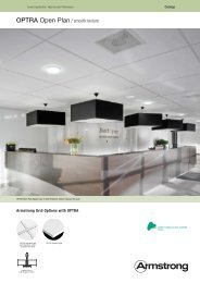
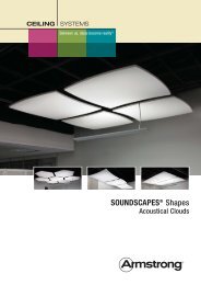
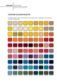
CEILING SYSTEMSBetween us, ideas be<strong>com</strong>e reality SOUNDSCAPES ® <strong>Shapes</strong><strong>Installation</strong> InstructionsDO NOT REMOVE PANELS FROM THE CARTON UNTIL YOUHAVE READ THESE INSTRUCTIONS IN THEIR ENTIRETY.LOCATE HARDWARE ACCESSORY KITS THAT SHIPPEDSEPARATELY1.0 GENERAL1.1 Product DescriptionSoundScapes <strong>Shapes</strong> Acoustical Clouds are flat fiberglass panelsdesigned to be installed in one of three suspension systems.There are 10 panel options that <strong>com</strong>e in a variety of shapes andthree nominal sizes: 1219mm x 1219mm, 1219mm x 1829mmand 1219mm x 2438mm.SoundScapes <strong>Shapes</strong> are designed to be suspended with<strong>Armstrong</strong> accessory kits and are engineered for use in seismicareas only when indicated <strong>com</strong>ponents are used and installed inaccordance with these installation instructions.1.2 Materials and FinishesSoundScapes <strong>Shapes</strong> panels are made from fiberglass andfinished on the front surface and four sides with DuraBriteacoustically transparent membrane. The back of the panel isunfinished with an embedded metal extrusion for use with thethree <strong>Armstrong</strong> suspension systems.There are seven standard color options for the finished panels.Field painting of white panels is not re<strong>com</strong>mended and shouldbe done only with extreme care in handling.1.3 Design Consideration for SagSoundScapes <strong>Shapes</strong> maintain a natural sag that may benoticeable when installed 152mm or less apart. Deflection up to3mm has been documented in some cases.1.3.1. Working With Fiberglass ProductsMAN-MADE VITREOUS FIBER CEILING PANELSWARNING THIS PRODUCT CONTAINS MAN-MADE VITREOUSFIBERS. POSSIBLE CANCER AND RESPIRATORY TRACTHAZARDS. CAN CAUSE TEMPORARY RESPIRATORY, SKINAND EYE IRRITATION.1.3.2. Precautionary Measures: During the installation becertain that the work site is well ventilated and avoid breathingdust. If high dust levels are anticipated during installation suchas with the use of power tools, use appropriate NIOSHdesignated dust respirator. All power cutting tools must beequipped with dust collectors. Avoid contact with skin or eyes.Wear long-sleeve, loose fitting clothes, gloves and eyeprotection.1.3.3. First Aid Measures: If contact occurs flush eyes and skinirritation with plenty of water for at least 15 minutes and removecontaminated clothing. After installing material, wash with warmwater and mild soap. Wash work clothes separately from otherclothing. Rinse washer thoroughly. Refer to <strong>Armstrong</strong> MSDS(which includes information on established occupationalexposure limits) which are available from <strong>Armstrong</strong> or youremployer.1.4 Storage and HandlingThe ceiling panel <strong>com</strong>ponents shall be stored in a dry interiorlocation and shall remain in original cartons prior to installationto avoid damage. The cartons shall be stored in a flat, horizontalposition. Save the carton cardboard insert for potential useduring installation as a guide for hanging the panels. The panelsshould not be removed from their carton until the suspensionsystem is ready. Proper care should be taken when handlingpanels to avoid damage and soiling, particularly with paneledges and the surface of color panels.Proper care should be taken to locate the hardware accessorykits shipped separately from the panels.1.5 Temperature During <strong>Installation</strong>The product can be installed where the temperature is between40°F (4°C) and 120°F (49°C). It cannot be used in exteriorapplications, where standing water is present, or where moisturewill <strong>com</strong>e in direct contact with the panel.1.6 Fire PerformanceSoundScapes <strong>Shapes</strong>, as with other architectural featureslocated in the ceiling plane, may obstruct or skew the existing orplanned fire sprinkler water distribution pattern, or possibly delaythe activation of the fire sprinkler or fire detection system.1
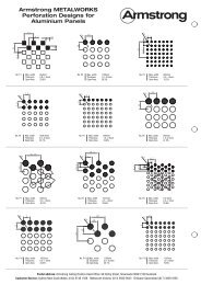
Designers and installers are advised to consult a fire protectionengineer, NFPA 13, and their local codes for guidance on theproper installation techniques where fire detection or suppressionsystems are present.2.0 COMPONENTS2.1 Panel <strong>Shapes</strong>Panels <strong>com</strong>e in ten different sizes and shapes. See data pageCS-3867 for exact product dimensions. Panels are flat but mayexhibit some natural deflection based on installation details.2.2 Suspension SystemsThere are three types of suspension system options for use withSoundScapes <strong>Shapes</strong>. Panels can be suspended individuallyfrom the deck with aircraft cable, individually direct attached todrywall with clips or suspended as a group from the deck with a<strong>com</strong>bination of frames, hooks and cables.The following section will describe each option and its installationprocedures in more detail.3.0 INSTALLATION3.1 GeneralBefore opening the panel carton, be sure to locate the hardwareaccessory kits needed for installation that were shippedseparately.SoundScapes <strong>Shapes</strong> may require two people to align andinstall each panel safely. DO NOT REMOVE THE PANELS FROMTHEIR CARTON until the appropriate suspension systemmethod has been prepared and is ready to accept the panels forinstallation.Panels cannot be used to support any other material. Thesuspension system chosen must be fastened to the structureand cannot be hung from any <strong>com</strong>mercial ceiling system.SoundScapes <strong>Shapes</strong> are not approved for exterior application.Each suspension system utilizes attachment points along themetal extrusion in the back of each panel. Each metal extrusionedge is marked at the center line to facilitate suspension withseveral methods and at 203mm offsets to facilitate hook locationattachments in group configurations.Here are the dimensions and locations of those extrusions ineach nominally sized panel:610mm1219mm1829mmThe cables attach below to the individual panel at the fourcorners of the back frame using the cable adjusters supplied inthe Deck Hanging Kit. (Note: In an individual panel suspension,you will not use the nuts and washers also supplied in that kit.These are for group hanging applications.)Screw the cable connectors into the threaded holes at the fourcorners of the metal extrusion and configure the cable andconnectors as shown. The height of a panel can be adjusted atthe Bottom End Cable Adjuster. When a final height is determinedand installation is <strong>com</strong>plete, cut off the excess cable wire notneeded from where it <strong>com</strong>es out of the side of the adjuster.1778mm1219mmAircraft Cableto DeckBottom EndCable AdjusterCorner BracketNote: A 2438mm Aircraft Cable length is included in the standardDeck Hanging Kit. If additional cable length is needed for highceiling applications, order the additional accessory kit for (4)9144mm Extended Hanging Cables (Item 625530).3.2.2 For 1219mm x 1829mm panels, the attachment points arethe midpoints (not the corners) of each side of the metalextrusion. First, line up the 1/4-20 nuts in the frames to the fourmid-point areas of the back frames. Then screw the cableconnectors into the 1/4-20 nuts in those locations. This providesthe appropriate support for a 1219mm x 1829mm panel. (Note:In an individual panel suspension, you will not use the nuts &washers also supplied in the Deck Hanging Kit. These are forgroup hanging applications.)610mm610mm610mm1168mm610mmNominal1219mm x 1219mmShapeNominal1219mm x 1829mmShapeNominal1219mm x 2438mmShape3.2 Suspending SinglePanels from the Deck3.2.1 When you are installinga single 1219mm x 1219mmpanel, you hang four cablesfrom the structure in a 1219mmsquare configuration. To fastenthe cable connectors to thestructure, use fasteners byothers that are <strong>com</strong>patible withthe structure. This part of theinstallation will utilize theGripper Structure Anchor andCap from the Deck Hanging Kit(Item 5450).Note: deck attachmenthardware by othersGripper StructureAnchorAircraft CableGripper Structure CapCable attaches topanel below viathe Bottom EndCable Adjuster3.2.3 For 1219mm x 2438mm panels, in addition to the fourcorners, you will need to attach two additional cables to themidpoints of the long sides of the frames. For the midpointattachments, first line up the 1/4-20 nuts in the frames to themid-point areas of the frames. Then screw the cable connectorsinto the 1/4-20 nuts in those locations. Along with the cornerattachments, this provides the appropriate extra support neededfor a 1219mm x 2438mm panel.1168mm610mm2388mm1829mm2
(Note: in an individual panel suspension, you will not use thenuts and washers also supplied in that kit. These are for grouphanging applications.)IMPORTANT SAFETY AND QUALITY NOTE: Do not allow anyportion of aircraft cable to drop below the panels while adjustingfinal panel height. To do so could cause injury to the installer ordamage to the edge of a panel.3.3 Installing Individual Panels Directly to Drywall CeilingsWith drywall attachment, the panels can be installed singly orgrouped in any arrangement that allows at least 51mm of spacebetween panels. The panel drywall clip drops the back of thepanel approximately 25mm from the face of the drywall.3.3.1 When installing 1219mm x 1219mm panels directly todrywall ceilings, you will attach panel drywall clips to the ceilingusing the appropriate fasteners by others (such as toggle boltsor moly bolts). You will install shoulder bolts into the threadedholes at the four corners of the metal extrusion on the back ofthe panel.Panel Drywall ClipWhen you have successfully positioned the panel and the boltsstop moving into the clips, lower the panel so the bolt heads arecaptured by the clips. This is the final step of the individualdrywall panel installation. The head of the bolt is captured withinthe end detail of the drywall clip so that panel will not move.3.3.2 For 1219mm x 1829mm panels, the drywall attachmentpoints are the mid-points (not the corners) of each side of themetal extrusion in the back of the panel. First, line up the 1/4-20nuts in the frames to the four mid-point areas of the backframes. Then screw the shoulder bolts into the 1/4-20 nuts inthose locations. This provides the appropriate support for a1219mm x 1829mm panel.1168mm610mm1778mm1219mmShoulder BoltCorner BracketThe panel drywall clips need to be located on the ceiling so theends of the clip with the detail that accepts bolt heads arearranged in a 610mm x 610mm square configuration (to line upwith the four corners of the metal extrusion no matter what theoutside panel shape is).To mark these locations in the ceiling, swing the top part of theclip out of the way to visually align the hanging point location(where the shoulder bolt will go) and mark the location on thedrywall ceiling above for the mounting attachment.Tip: rotate top of assemblyout of the way to markattachment points ondrywall ceilingThen proceed with the installation of the drywall clips to theceiling in the same manner as for 1219mm x 1219mm panels,and with the panel to the clips in the same manner as for smallerpanels.NOTE: The alignment of a 1219mm x 1829mm panel to theinstalled clips is even more challenging due to its larger size.Please handle the panel with care and patience, particularly if itis a color panel, during this process. It is helpful to have asecond person who can see where the bolts are to help guidethe panel placement onto the clips.3.3.3 For 1219mm x 2438mm panels, in addition to the fourcorners, you will need to attach two additional shoulder bolts tothe midpoints of the long sides of the frames. For the midpointattachments, first line up the 1/4-20 nuts in the frames to themid-point area of the frames. Then screw the shoulder bolts intothe 1/4-20 nuts in those locations. Along with the cornerattachments, this provides the appropriate extra support neededfor a 1219mm x 2438mm panel.2388mmWhen the drywall clips are mounted in the ceiling and theshoulder bolts are mounted in the panel frame, lift the panel tothe ceiling, carefully lining up all four bolts with the open ends ofthe clips and slide the panel so that the bolts enter the ends ofthe clips.1168mm610mm1829mmShoulder Boltattached to metal extrusionin back of panelAttachment to deckby othersDrywall ClipassemblyNOTE: Aligning the bolts to the clips can be somewhat difficultbecause you cannot see the exact locations once the panel israised. Be sure to handle the panel and edges carefully duringthis process. It is helpful to have a second person who can seewhere the bolts are help guide the panel placement onto theclips.NOTE: The alignment of a 1219mm x 2438mm panel to theinstalled clips is also challenging given its larger size. Pleasehandle the panel with care and patience, particularly if it is acolor shape, during this process. It is helpful to have a secondperson who can see where the bolts are help guide the panelplacement onto the clips.3.4 Suspending Groups of Panels3.4.1 When you suspend panels in a group configuration, it ismore efficient to use grouping frames and suspension hooks forsupport. This also provides a group ceiling system designed foruse in all seismic areas.3
First, determine the length of the 3658mm grouping frame<strong>com</strong>ponents needed based on your layout, and then cut andarrange them so that panels have at least 51mm of clearancebetween them. Shown below are a number of group configurationoptions with the frame arrangement needed to support them.These arrangements all have the minimum 51mm clearancebetween panels. Some grouping options shown on the web andin the data page may have more than 51mm spacing betweenpanels. CAD details are available on our website for thesegrouping options.3.4.4 Now let’s look at guidelines for field-cut frame lengths forthe typical group assemblies.If you take a close look at the examples below, you can see twothings: 1) the layout of the grouping frames and where the panelhooks will engage them, and 2) the outline of the metalextrusions on the back of the panels and how the frames go51mm beyond them.3.4.4.1 Group Option 1: Because these panels are a nominal1219mm x 1219mm dimension, 1219mm spacing of the framesand field cutting them to four pieces at 1931mm each will createthe minimum 51mm gap between panels.1219mmGroup Option 1 Group Option 2 Group Option 31219mm610mmGroup Option 4 Group Option 53.4.2 If your application has more than 51mm spacing betweenpanels, you must increase the center distances betweengrouping frames accordingly. If you increase their lengths, youmay also need additional grouping frame kits and, potentially,some frame splice kits to connect 3658mm frames.See drawing below of how to attach two pieces of groupingframes with 10 inch frame splices.Frame lengths:1931mm610mmx = panel hook locations during installation= re<strong>com</strong>mended hanging point locationNotes:– add or subtract 51mm to frame lengthdimensions for each 51mm increase/decrease in spacing between panelsGeneral Notes:– always hang grouping framefrom lower frame member– hanging point spacing alongframe not to exceed 1219mm1/4-20 x 3/4˝ Boltwith WasherGrouping FrameThe frames need to extend 51m past the point where the panelhooks will engage them. In this example, the frames should be1931mm long, and they should be installed on 1219mm centers.This ensures that the hooks will not slip off the frames. This alsominimizes the visibility of the hardware when the panels aresuspended.Tip: Cut frame on center lineof 51mm of hole spacing254mm Frame Splice1/4-20 Nut14˝Note: There are guidelines on the SoundScapes <strong>Shapes</strong> datapage (CS-3867) for the grouping options outlined above to showwhat type and how many accessory kits may be needed.However, all of the published grouping guidelines are based onthe minimum 51mm clearance between panels. If you changethe center distances, you will need to figure out the appropriateadditions to accessory kits(additional grouping framesand/or frame splices) thatmay be needed. Centerdistances must be changedin 51mm increments. Youmay call TechLine forassistance; however, theydo not provide layout anddesign services.3.4.3 In every groupsuspension system, youwill utilize multiple DeckHanging Kits to suspendthe grouped panel systemto the deck. This portion ofthe Deck Hanging Kit isused to suspend thegrouping frames to thedeck, with attachment tothe deck by others.Note: deck attachmenthardware by othersGripper StructureAnchorAircraft CableGripper Structure CapCable attaches togrouping frame belowvia the Bottom EndCable Adjuster14˝<strong>Installation</strong> Tip: Cut on the center line of the 51mm hole spacingof the grouping frames.Note: If more than 51mm of spacing is desired between panels,add 51mm or more (in 51mm increments) to all framedimensions to add that visual spacing. See CAD details on thewebsite for actual spacing between panels when differentshapes are used in this configuration.3.4.4.2 Group Option 2: Looking at this example, two rows offrames in one direction are needed for support. This prevents theassembly from tilting to one side or the other. Note that theminimum length for the long frame dimensions will be 4370mm.This will require use of a 254mm splice. Also note that you willneed to add at least 152mm (or more in 152mm increments) tothe long frame length dimensions for each 51mm increase ofspacing desired between panels.4
1219mm1219mm1219mm1219mm1219mmFrame lengths:1016mm3353mm712mm51mm51mm51mmx = panel hook locations during installation= re<strong>com</strong>mended hanging point location= 254mm frame spliceNotes:– add or subtract 1829mm to overall (4370mm)frame length dimensions for each 51mmincrease/decrease in spacing between panels– 407mm dimension will remain unchangedregardless of visual spacing– 254mm splice is required for framelengths longer that 3658mm407mmGeneral Notes:– always hang grouping frame fromlower frame member– hanging point spacing along framenot to exceed 1219mm1219mm1219mm51mm 51mmThe panel hooks will be centered in one direction and must belocated 203mm off center in the other direction. You must beaware of these locations when placing the hooks on the back ofthe panels. The back panel metal extrusions are marked withthese 203mm-off-center locations. (See section 3.4.6.)3.4.4.3 Group Option 3: Looking at this example with a<strong>com</strong>bination of 1219mm x 1219mm and 1219mm x 1829mmpanels, review the two different lengths of grouping framesneeded and the different hook locations to support the largerpanels. Also note that you will need to add at least 51mm (ormore in 51mm increments) to all frame dimensions for each51mm increase of spacing desired between panels.1829mmFrame lengths:3150mm610mm51mm2134mm407mm51mmx = panel hook locations during installation= re<strong>com</strong>mended hanging point locationNotes:– add or subtract 102mm to frame lengthdimensions for each 51mm increase/decrease in spacing between panels– as visual spacing increases, use 254mmsplice as neededGeneral Notes:– always hang grouping framefrom lower frame member– hanging point spacing alongframe not to exceed 1219mm3.4.4.5 Group Option 5: Here is another grouping example withthe panels offset in the group. This type of installation is more<strong>com</strong>plex with four different base lengths of grouping framesrequired.610mm610mm1219mm51mm1219mm610mm610mm51mm610mmFrame lengths:1931mm2540mm51mmx = panel hook locations during installation= re<strong>com</strong>mended hanging point locationNotes:– add or subtract 51mm to frame lengthdimensions for each 51mm increase/decrease in spacing betweenpanels– as visual spacing increases,use 254mm splice as neededGeneral Notes:– always hang grouping framefrom lower frame member– hanging point spacing alongframe not to exceed 1219mm3.4.4.4 Group Option 4: In this configuration with 9 panels, allof the grouping frames are equal length at 3150mm and spaced1219mm apart in order to have at least 51mm spacing betweenpanels. Because of the number of panels linked in this design,if you want to increase visual spacing between the panels, youneed to add at least 102mm (in 102mm increments) to allgrouping frame dimensions for each 51mm increase in spacingbetween panels.Frame lengths:1931mm3150mm712mm2845mmx = panel hook locations during installation= re<strong>com</strong>mended hanging point locationNotes:– for each 2˝ increase/decrease inspacing between panels add orsubtract from the frame lengthdimensions as follows:frameframeframeframe- 51mm- 102mm- stays the same- 51mm57mmGeneral Notes:– always hang grouping framefrom lower frame member– hanging point spacing alongframe not to exceed 1219mmIf you want to increase the spacing distance between the panelsfrom the minimum 51mm as shown here with circle panels, youwill need to change the frame lengths in the following way.NOTE: There is more distance between the panels whenhexagon shapes are used in this application. For every 51mmincrease in spacing between panels, increase the lengths ofeach numbered frame accordingly:• Frame 1 – by 51mm• Frame 2 – by 102mm• Frame 3 – stays the same• Frame 4 – by 51mm5
3.4.5 <strong>Installation</strong> Process: Group Frame AssemblyNow that you have reviewed some of the possible groupdesigns, the group installation process is as follows.All grouping frames <strong>com</strong>e with four 3658mm long pieces to a kit.First, cut the frames to the appropriate lengths needed for yourapplication. The aluminum frames can be field cut with ahacksaw.Note: If your design requires grouping frames longer than3658mm, you will need to use a 254mm connector, as shown, byordering the Frame Splice Kit.Tip: Cut frame on center lineof 51mm hole spacingAircraft Cable to Deck1/4-20 x 3/4˝ Boltwith WasherGrouping Frame154mm Frame Splice1/4-20 NutNext, arrange the grouping frames into the desired design anddetermine top and bottom elements to maximize the efficiencyof installation hanging points. In all cases, the top or “upper”grouping frames should be oriented with the “U” shape up. Thebottom or “lower” grouping frames should have the “U” shapedown, as shown below.The bottom grouping frames are the support mechanisms thatwill be suspended from structure. You decide which struts will beused as the supporting struts by placing them in the groupingfirst. If the first struts you install are running north and south, forexample, they will be supported from structure. The strutsrunning east and west will then sit on top of them.Where frames cross over each other in the design, you use aframe alignment spacer to establish 90 degree alignment, andnuts and bolts to secure the connection. Holes for the bolts arepre-drilled in the grouping frame every 51mm along its length.Secure each spacer through the top frame and to the bottomframe as shown with nuts, bolts and washers provided in theFrame Alignment Kits.Finally, you will space aircraft cables from the Deck Hanging Kitsat least every 1219mm along the supporting (bottom) frame. Inthe bottom grouping frame at the appropriate 1219mm locations,the bottom end cable adjuster is inserted into one of thepre-drilled holes. Use the nuts with washer to secure the cableadjuster to the frame.1/4-20 x 1-1/4 Bolt“Upper” Grouping Frame<strong>Installation</strong> Tip: You can lay out the frame configuration on thefloor to connect all the <strong>com</strong>ponents and hang the entireassembly as a unit. Or, you can hang the frames one by onefrom structure as you build the framework for the grouping.Individual jobsite conditions may determine the most convenientmethod to build the framework.3.4.6 <strong>Installation</strong> Process: Attaching Hooks to the PanelsOnce the group assembly is finished and suspended, secure thesupport hooks to the backs of the panels. You will need 4 hooks– 2 “high” and 2 “low” – for each panel. There are 4 of theappropriate size hooks in each Panel Hook Kit, so you need onekit per shape for all 1219mm x 1219mm and 1219mm x 1829mmpanels. Exception: 1219mm x 2438mm panels need 2 Hook Kitseach because six points of attachment are needed to supportthe larger panel.As you fasten the hooks to the frames on the back of the panels,you must be aware of the location of the “high” hooks versus the“low” hooks. High hooks are always across from each other, andlow hooks are always across from each other.If the shape is not symmetrical (i.e. everything except squaresand circles), you must also determine where the high hooks andlow hooks need to be placed in the panel in order to meet thedesign layout. This means referencing the center marks on theframes or the marks that are 8 inches offset from the center.Refer back to typical group installation designs to see whichtypes of configurations have offsetting hooks.Note: use hook locator to correctlyplace hooks at pre-marked locationsPanel Hook1/4-20 x 3/8˝ Boltattaches to 1/4-20 square nutinside back-channelBack-channelmarked at center and 8˝ O.C.to assist with hook placementThere is a notch cut into the base of the hooks so you can lineup the hooks with the appropriate marks on the frame. The1/4-20 nuts for securing the hooks to the frames are already inthe back channels. Line up the nuts with the correct location forthe hooks and screw the hooks to the panel using the bolts inthe Panel Hook Kit.NOTE: The notch in the base of the hooks will always face theoutside of the panel.Bottom End Cable AdjusterNote: back-channel is marked at centerand 8˝ O.C. to assist with hook placement“Lower” Grouping FrameFrame Alignment Spacer1/4-20 Nut with Washer1/4-20 Nut with Washer6
3.4.7 <strong>Installation</strong> Process: Hanging the PanelsNow you’re ready to install the panels onto the group hangingsystem up in the ceiling.3.4.7.1 First, rotate the panel about 10 degrees clockwise underthe grouping frame assembly and below the frame intersection.3.4.7.4 Let the panel drop carefully into place with the four panelhooks engaging the upper and lower frames.3.4.7.5 Repeat as necessary for the number of panels you havein your group configuration.Note: The panel hooks will be positioned correctly if you haveinstalled them with the notch facing the outside of the panel andhave high and low hooks on opposite sides.3.4.7.2 Then, lift the panel until the back metal extrusion meetsthe underside of the lower grouping frame. Start rotating thepanel counter-clockwise, in the direction shown below.3.4.7.6 Adjust the hanging height of group system as needed.IMPORTANT SAFETY AND QUALITY NOTE: Do not allow anyportion of aircraft cable to drop below the panels while adjustingfinal panel height. To do so could cause injury to the installer ordamage to the edge of a panel.3.5 Installing <strong>Shapes</strong> Below an Existing Suspended Ceiling3.4.7.3 When the panel is rotated about 10 degrees, the bottomof the hooks should engage the grouping frames.GripperStructure Anchor1/4-20NC ThreadedRod not includedEscutcheonSuspension cables used with SoundScapes <strong>Shapes</strong> suspendedfrom the deck (either individually or as a group) should notimpose any lateral force on an existing suspended ceiling.1. The structure gripper anchor must be mounted to a supportat or above the existing ceiling.2. Use 1/4– 20 threaded rod attached to structure to secure thestructure gripper anchor at the correct height.7
3. Use diagonal bracing to structureto provide support.4. Use the optional escutcheonaccessory kit to conceal thestructure gripper anchor wheninstalled above the ceiling level.Escutcheon Kit #7006• (2) Collars with set screws• (2) Escutcheons (51mm)3.6 Panel PenetrationsThe panels can be field cut for penetrations such as lighting orsprinklers as long as the fixtures are independently supportedand not supported in any way by the panel suspension system.3.7 Seismic Restraint*The International Building Code allows architectural <strong>com</strong>ponentsto swing freely as long as they will not be damaged or causedamage. <strong>Shapes</strong> suspended individually with aircraft cable willswing no more than 457mm in any direction for each panel.<strong>Shapes</strong> direct attached to drywall or suspended in groupsystems have been engineered for application in all seismicareas.*Pendulum reaction information is based on full scale testing and<strong>com</strong>puter modeling conducted at the Structural EngineeringEarthquake Simulation Lab located at the State University of NewYork at Buffalo.4.0 CLEANINGUse a clean, dry, soft white cloth to wipe off any dirt orfingerprints. Regular light dusting of the back side of the panel isre<strong>com</strong>mended.MORE INFORMATIONFor <strong>com</strong>plete technical information, detail drawings, CAD design assistance, installation information and many other technicalservices, call your local <strong>Armstrong</strong> office.For the latest product selection and specification data, visit armstrong.<strong>com</strong>/shapesAll Trademarks are owned by AWI Licensing CompanyLA-297302-708NSW<strong>Armstrong</strong> World Industries Pty. Ltd.99 Derby Street,Silverwater NSW 2128Telephone (02) 9748 1588Facsimile (02) 9748 8449VIC/TAS<strong>Armstrong</strong> World Industries Pty. Ltd.29-39 Mills Road,Braeside VIC 3195Telephone (03) 9580 9633Facsimile (03) 9587 5139QLD/NT<strong>Armstrong</strong> World Industries Pty. Ltd.6 Barrinia Street,Slacks Creek QLD 4127Telephone (07) 3809 5565Facsimile (07) 3809 5507SABoral Plasterboard39 Burleigh AvenueWoodville North SA 5012Telephone (08) 7002 6300Facsimile 08) 8345 0809WACeiling Manufacturers of Australia Pty. Ltd.5 Irvine Street,Bayswater WA 6053Telephone (08) 9271 0777Facsimile (08) 9272 2801New ZealandForman Building Systems Ltd.PO Box 12349,Penrose, AucklandTelephone 64-9-276 4000Facsimile 64-9-276 4141www.armstrongceilings.<strong>com</strong>.au8